JP4678281B2 - Semiconductor substrate cutting device - Google Patents
Semiconductor substrate cutting deviceDownload PDFInfo
- Publication number
- JP4678281B2 JP4678281B2JP2005331213AJP2005331213AJP4678281B2JP 4678281 B2JP4678281 B2JP 4678281B2JP 2005331213 AJP2005331213 AJP 2005331213AJP 2005331213 AJP2005331213 AJP 2005331213AJP 4678281 B2JP4678281 B2JP 4678281B2
- Authority
- JP
- Japan
- Prior art keywords
- semiconductor substrate
- liquid
- specific gravity
- substrate cutting
- cutting device
- Prior art date
- Legal status (The legal status is an assumption and is not a legal conclusion. Google has not performed a legal analysis and makes no representation as to the accuracy of the status listed.)
- Expired - Fee Related
Links
Images


Landscapes
- Laser Beam Processing (AREA)
- Dicing (AREA)
Description
Translated fromJapaneseこの発明は、半導体基板をその厚さ方向に分断する半導体基板の分断装置に関する。 The present invention relates to a semiconductor substrate cutting apparatus for cutting a semiconductor substrate in its thickness direction.
近年、半導体集積回路やMEMS(Micro Electro Mechanical Systems)を形成したシリコンウェハ(以下、ウェハという)を各々の半導体チップに分離するダイシング工程では、レーザ光を用いたダイシング工程(レーザダイシング)の検討や研究が進められており、例えば、下記特許文献1にレーザによるウェハの加工技術が開示されている。
図7は、レーザ光を用いたダイシング工程を示す説明図である。図7(A)はレーザ光の照射による改質領域形成工程の説明図であり、図7(B)は分断工程の説明図である。
図7(A)に示すように、レーザ光Lを照射するレーザヘッドHは、レーザ光Lを集光する集光レンズCVを備えており、レーザ光Lを所定の焦点距離で集光させることができる。改質領域形成工程では、レーザ光Lの集光点Pがウェハの半導体基板Wの基板面から深さdの箇所に形成されるように設定したレーザ光照射条件で、半導体基板Wを分断する分断予定ラインDL上に沿って(図中手前方向)レーザヘッドHを移動させ、レーザ光Lを半導体基板Wの基板面から半導体基板W内部へ照射する。これにより、レーザ光Lの集光点Pが走査された深さdの経路には、多光子吸収による改質領域Kが形成される。
ここで、多光子吸収とは、物質が複数個の同種もしくは異種の光子を吸収することをいう。その多光子吸収により、半導体基板Wの集光点Pおよびその近傍では、光学的損傷という現象が発生し、これにより熱ひずみが誘起され、その部分にクラックが発生し、そのクラックが集合した層、つまり改質領域Kが形成される。
レーザ光Lがパルス波の場合、レーザ光Lの強度は、集光点Pのピークパワー密度(W/cm2)で決まり、例えばピークパワー密度が1×108(W/cm2)以上でパルス幅が1μs以下の条件で多光子吸収が発生する。レーザ光Lとしては、例えば、YAG(Yttrium Aluminum Garnet)レーザによるレーザ光を用いる。そのレーザ光Lの波長は、例えば1064nmの赤外光領域の波長である。
続いて、図7(B)に示すように、半導体基板Wの面内方向(図中矢印F2、F3で示す方向)に応力を負荷することにより、改質領域Kを起点にして、基板厚さ方向にクラックCを進展させて、半導体基板Wを分断予定ラインDLに沿って分断する。
図8は、半導体基板Wの基板面におけるレーザ光Lの反射の説明図である。
図8(A)に示すように、空気と半導体基板Wとは屈折率の差が大きいため、その界面である基板面においてレーザ光Lが反射し、その反射光Rの分だけ改質領域Kを形成するためのレーザ光Lの照射効率が低下するという問題があった。
そこで、図8(B)に示すように、半導体基板Wの基板面にレーザ光Lの反射を防止する反射防止膜Fを形成して反射光Rを少なくする技術が適用されている(特許文献2参照)。
In recent years, in a dicing process for separating a silicon wafer (hereinafter referred to as a wafer) on which a semiconductor integrated circuit or MEMS (Micro Electro Mechanical Systems) is formed into each semiconductor chip, a dicing process using laser light (laser dicing) has been studied. For example,
FIG. 7 is an explanatory diagram showing a dicing process using laser light. FIG. 7A is an explanatory diagram of a modified region forming process by laser light irradiation, and FIG. 7B is an explanatory diagram of a dividing process.
As shown in FIG. 7A, the laser head H that irradiates the laser light L includes a condensing lens CV that condenses the laser light L, and condenses the laser light L at a predetermined focal length. Can do. In the modified region forming step, the semiconductor substrate W is divided under the laser light irradiation conditions set so that the condensing point P of the laser light L is formed at a position of a depth d from the substrate surface of the semiconductor substrate W of the wafer. The laser head H is moved along the planned dividing line DL (frontward in the figure), and the laser beam L is irradiated from the substrate surface of thesemiconductor substrate W into the semiconductor substrate W. As a result, a modified region K by multiphoton absorption is formed in a path of depth d where the condensing point P of the laser beam L is scanned.
Here, multiphoton absorption means that a substance absorbs a plurality of the same or different photons. Due to the multiphoton absorption, a phenomenon called optical damage occurs at the condensing point P of the semiconductor substrate W and in the vicinity thereof, thereby inducing a thermal strain, and a crack is generated in the portion, and the layer in which the crack is assembled. That is, the modified region K is formed.
When the laser beam L is a pulse wave, the intensity of the laser beam L is determined by the peak power density (W / cm2 ) at the condensing point P. For example, the pulse is generated when the peak power density is 1 × 10 8 (W / cm2 ) or more. Multiphoton absorption occurs under conditions where the width is 1 μs or less. As the laser light L, for example, laser light from a YAG (Yttrium Aluminum Garnet) laser is used. The wavelength of the laser light L is, for example, a wavelength in the infrared light region of 1064 nm.
Subsequently, as shown in FIG. 7B, by applying stress in the in-plane direction of the semiconductor substrate W (directions indicated by arrows F2 and F3 in the figure), the substrate thickness starts from the modified region K. The crack C is advanced in the vertical direction, and the semiconductor substrate W is divided along the line to be divided DL.
FIG. 8 is an explanatory diagram of the reflection of the laser light L on the substrate surface of the semiconductor substrate W. FIG.
As shown in FIG. 8A, since the difference in refractive index between air and the semiconductor substrate W is large, the laser beam L is reflected on the substrate surface that is the interface, and the modified region K is reflected by the reflected light R. There has been a problem that the irradiation efficiency of the laser beam L for forming is reduced.
Therefore, as shown in FIG. 8B, a technique for reducing the reflected light R by forming an antireflection film F for preventing the reflection of the laser light L on the substrate surface of the semiconductor substrate W is applied (Patent Document).see 2).
しかし、反射防止膜Fを形成する工程が必要であるため、デバイス設計上の制約となるとともに、コストが上昇することがあった。また、このような反射防止膜Fは、レーザ光Lの半導体基板W内部への入射も抑制してしまうため、必ずしもレーザ光Lの照射効率が向上しないという問題があった。 However, since a process of forming the antireflection film F is necessary, there are restrictions on device design and the cost may increase. Moreover, since such an antireflection film F also suppresses the incidence of the laser beam L into the semiconductor substrate W, there is a problem that the irradiation efficiency of the laser beam L is not necessarily improved.
そこで、この発明は、半導体基板の基板面に反射防止膜の形成が不要で、半導体基板内部へのレーザ光の入射を抑制することなく、レーザ光の反射を抑制し、レーザ光の照射効率を向上させることができる半導体基板の分断装置を実現することを目的とする。 Therefore, the present invention does not require the formation of an antireflection film on the substrate surface of the semiconductor substrate, suppresses the reflection of the laser beam without suppressing the incidence of the laser beam into the semiconductor substrate, and improves the irradiation efficiency of the laser beam. An object of the present invention is to realize a semiconductor substrate cutting apparatus that can be improved.
請求項1に記載の発明は、
半導体基板をその厚さ方向に分断するための分断予定ラインに沿ってレーザ光を照射するレーザヘッドを前記半導体基板の基板面に対して相対移動させながら、前記半導体基板の内部に集光点が合うように前記基板面へレーザ光を照射し、前記集光点に多光子吸収による改質領域を形成する半導体基板の分断装置において、
空気より屈折率が大きい液体を前記レーザ光の出射部と前記基板面との間に供給することにより、前記液体を前記レーザ光の出射部と前記基板面との間に充填する供給手段を備え、
前記液体が前記レーザ光の出射部と前記基板面との間に充填された状態で、前記半導体基板の内部に集光点を合わせて前記レーザ光を照射し、
前記供給手段は、前記半導体基板を前記液体に浸漬する浸漬部材であり、
前記浸漬部材には、比重が異なり、お互いに混合しない異なる種類の液体が貯留されており、比重の小さい方の液体中で前記半導体基板に前記レーザ光の照射を行った後に、前記半導体基板を比重の大きい方の液体中に移動させて浸漬することを技術的特徴とする。
The invention described in
While moving the laser head that irradiates the laser beam along the planned dividing line for dividing the semiconductor substrate in the thickness direction relative to the substrate surface of the semiconductor substrate, a condensing point is formed inside the semiconductor substrate. In the semiconductor substrate cutting apparatus that irradiates the substrate surface with laser light so as to fit, and forms a modified region by multiphoton absorption at the condensing point,
Supply means for filling the liquid between the laser light emitting portion and the substrate surface by supplying a liquid having a refractive index larger than that of air between the laser light emitting portion and the substrate surface. ,
In a state where the liquid is filled between the laser light emitting portion and the substrate surface, the laser light is irradiatedwith the focusing point inside the semiconductor substrate,
The supply means is an immersion member that immerses the semiconductor substrate in the liquid,
The immersion member stores different types of liquids having different specific gravities and not mixed with each other, and after the semiconductor substrate is irradiated with the laser light in the liquid having a smaller specific gravity, the semiconductor substrate is It is technically characterizedby beingmoved and immersed in a liquid having a higher specific gravity .
請求項2に記載の発明は、
請求項1に記載の半導体基板の分断装置において、
前記比重の小さい方の液体は水であり、前記比重の大きい方の液体は液状有機化合物であることを技術的特徴とする。
The invention described in
In the semiconductor substrate cutting device according to
The liquid having the smaller specific gravity is water, and the liquid having the larger specific gravity is a liquid organic compound .
請求項3に記載の発明は、
請求項1に記載の半導体基板の分断装置において、
前記比重の小さい方の液体は比重が1より大きい液状有機化合物であることを技術的特徴とする。
The invention according to
In the semiconductor substrate cutting device according to
Smaller liquid of the specific gravity and technically characterized in that thespecific gravity of greater than 1 liquid organic compound.
請求項4に記載の発明は、
請求項1に記載の半導体基板の分断装置において、
前記比重の小さい方の液体がアルコールであることを技術的特徴とする。
The invention according to
In the semiconductor substrate cutting device according to
A technical featureis thatthe liquid having the smaller specific gravity is alcohol .
請求項5に記載の発明は、
請求項1に記載の半導体基板の分断装置において、
前記比重の小さい方の液体が液体窒素であることを技術的特徴とする。
The invention described in claim 5
In the semiconductor substrate cutting device according to
A technical featureis thatthe liquid having the smaller specific gravity is liquid nitrogen .
請求項6に記載の発明は、
請求項1に記載の半導体基板の分断装置において、
前記比重の小さい方の液体が液体二酸化炭素であることを技術的特徴とする。
The invention described in claim 6
In the semiconductor substrate cutting device according to
A technical featureis thatthe liquid having the smaller specific gravity is liquid carbon dioxide .
請求項7に記載の発明は、
請求項1に記載の半導体基板の分断装置において、
前記比重の小さい方の液体を前記半導体基板の基板面で流動させる流動手段を備えたことを技術的特徴とする。
The invention described in claim 7
In the semiconductor substrate cutting device according to
A technical feature isprovided with flow means for flowing the liquid having the smaller specific gravity on the surface of the semiconductor substrate .
請求項8に記載の発明は、
請求項1に記載の半導体基板の分断装置において、
前記比重の小さい方の液体に振動を付与する振動手段を備えたことを技術的特徴とする。
The invention according to claim 8 provides:
In the semiconductor substrate cutting device according to
A technical feature is thatvibration means for applying vibration to the liquid having the smaller specific gravity is provided .
請求項9に記載の発明は、
請求項1〜8のいずれか1項に記載の半導体基板の分断装置において、
前記半導体基板に加振する加振手段を備えたことを技術的特徴とする。
The invention according to claim 9 is:
In the semiconductor substrate cutting device according to any one of
A technical feature is thatvibration means for exciting the semiconductor substrate is provided .
請求項10に記載の発明は、
請求項1〜9のいずれか1項に記載の半導体基板の分断装置において、
前記比重の小さい方の液体に気泡を導入し、その導入した気泡を前記半導体基板の基板面に吹き付ける気泡導入手段を備えたことを技術的特徴とする。
The invention according to
In the semiconductor substrate cutting device according to any one of
A technical feature is thatbubble introduction means is provided for introducing bubbles into the liquid having a smaller specific gravity and blowing the introduced bubbles onto the substrate surface of the semiconductor substrate .
請求項11に記載の発明は、
請求項1〜10のいずれか1項に記載の半導体基板の分断装置を使用した半導体基板の分断方法であって、
前記改質領域が形成された前記半導体基板を、前記前記改質領域を起点にして、前記分断予定ラインに沿って厚さ方向に分断して半導体チップを得ることを技術的特徴とする。
The invention according to
A semiconductor substrate cutting method using the semiconductor substrate cutting device according to any one of
A technical feature is thata semiconductor chip is obtained by dividing the semiconductor substrate on which the modified region is formed in the thickness direction along the planned dividing line, starting from the modified region .
請求項1に記載の発明によれば、半導体基板をその厚さ方向に分断するための分断予定ラインに沿ってレーザ光を照射するレーザヘッドを半導体基板の基板面に対して相対移動させながら、半導体基板の内部に集光点が合うように基板面からレーザ光を照射し、集光点に多光子吸収による改質領域を形成する半導体基板の分断装置において、空気より屈折率が大きい液体をレーザ光の出射部と基板面との間に供給する供給手段を備えており、半導体基板の内部に集光点を合わせてレーザ光を照射するため、半導体基板と空気との屈折率の差に比べて、基板面におけるレーザ光の屈折率の差を小さくできるので、基板面におけるレーザ光の反射を抑制することができ、レーザ光の照射効率を向上することができる。
したがって、半導体基板の基板面に反射防止膜の形成が不要で、半導体基板内部へのレーザ光の入射を抑制することなく、レーザ光の反射を抑制し、レーザ光の照射効率を向上することができる半導体基板の分断装置を実現することができる。According to the invention of
Therefore, it is not necessary to form an antireflection film on the substrate surface of the semiconductor substrate, and it is possible to suppress the reflection of the laser beam and improve the irradiation efficiency of the laser beam without suppressing the incidence of the laser beam into the semiconductor substrate. A semiconductor substrate cutting device that can be realized can be realized.
請求項1に記載の発明によれば、液体がレーザ光の出射部と基板面との間に充填された状態で、レーザ光が半導体基板の内部に集光点を合わせて半導体基板の基板面から照射されるため、レーザ光の光路に空気と液体との界面が存在せず、空気と液体との界面におけるレーザ光の反射がないので、レーザ光の照射効率を向上することができる。
According to thefirst aspect of the present invention, in a state where the liquid is filled between the laser light emitting portion and the substrate surface, the laser light is focused on the inside of the semiconductor substrate and the substrate surface of the semiconductor substrate. Since there is no interface between air and liquid in the optical path of the laser light and there is no reflection of laser light at the interface between air and liquid, the irradiation efficiency of the laser light can be improved.
また、請求項1に記載の発明によれば、半導体基板は液体に浸漬されているため、レーザ光の出射部と半導体基板との間に、確実に液体を供給できるので、確実にレーザ光の照射効率を向上させることができる。
そして、請求項1に記載の発明によれば、比重の小さい方の液体中でレーザ光を照射するときには、レーザ光の反射を抑制し、レーザ光の照射効率を向上させることができる。その後、半導体基板を比重の大きい方の液体中に移動させ、浸漬するため、レーザ光の照射によって基板面に発生した付着物を浮力で除去することができる。
ここで、請求項2に記載の発明のように、比重の小さい液体として水を、比重の大きい液体としては液状有機化合物を用いることができる。
レーザ光の出射部と基板面との間に供給する液体として、請求項3に記載の発明のように比重が1より大きい液状有機化合物を用いると、水よりも比重が大きいため浮力が増大するので、基板面に付着した付着物をより効果的に除去することができる。
レーザ光の出射部と基板面との間に供給する液体として、請求項4に記載の発明のようにアルコールを用いると、浸漬後の乾燥時間を短くすることができる。
レーザ光の出射部と基板面との間に供給する液体として、請求項5または請求項6に記載の発明のように液体窒素または液体二酸化炭素を用いると、超臨界乾燥により表面張力の影響を少なくすることができるので、MEMSなどの可動部を固着させることがない。
According to thefirst aspect of the present invention, since the semiconductor substrate is immersed in the liquid, the liquid can be reliably supplied between the laser beam emitting portion and the semiconductor substrate. Irradiation efficiency can be improved.
According to the first aspect of the present invention, when the laser beam is irradiated in the liquid having the smaller specific gravity, the reflection of the laser beam can be suppressed and the irradiation efficiency of the laser beam can be improved. Thereafter, the semiconductor substrate is moved and immersed in the liquid having the higher specific gravity, so that the deposits generated on the substrate surface by the laser light irradiation can be removed by buoyancy.
Here, as in the invention described in
When a liquid organic compound having a specific gravity greater than 1 is used as the liquid supplied between the laser beam emitting portion and the substrate surface, the buoyancy increases because the specific gravity is greater than that of water. Therefore, the deposit | attachment adhering to the board | substrate surface can be removed more effectively.
When alcohol is used as the liquid supplied between the laser beam emitting portion and the substrate surface as in the invention described in
When liquid nitrogen or liquid carbon dioxide is used as the liquid supplied between the laser beam emitting portion and the substrate surface as in the invention described in claim 5 or claim 6, the influence of surface tension is exerted by supercritical drying. Since it can be reduced, movable parts such as MEMS are not fixed.
請求項7に記載の発明によれば、液体が半導体基板の基板面で流動するので、液体の流動の物理的作用により、基板面に付着している付着物を基板面から除去できる。そのため、レーザ光の照射を妨げる付着物を除去できるので、レーザ光の照射効率を向上させることができる。
According to theseventh aspect of the invention, since the liquid flows on the substrate surface of the semiconductor substrate, the deposits attached to the substrate surface can be removed from the substrate surface by the physical action of the liquid flow. Therefore, since the deposits that hinder the irradiation of the laser beam can be removed, the irradiation efficiency of the laser beam can be improved.
請求項8に記載の発明によれば、浸漬部材内の液体に振動を付与することにより、基板面と液体との間にせん断力が作用するため、基板面に付着している付着物を効率よく除去することができる。そのため、レーザ光の照射を妨げる付着物を除去できるので、レーザ光の照射効率を向上させることができる。
According to theeighth aspect of the present invention, since the shearing force acts between the substrate surface and the liquid by applying vibration to the liquid in the immersion member, the adhering matter adhering to the substrate surface is efficiently treated. Can be removed well. Therefore, since the deposits that hinder the irradiation of the laser beam can be removed, the irradiation efficiency of the laser beam can be improved.
請求項9に記載の発明によれば、半導体基板が加振されることにより、基板面と液体との間にせん断力が作用するため、基板面に付着している付着物を効率よく除去することができる。そのため、レーザ光の照射を妨げる付着物を除去できるので、レーザ光の照射効率を向上させることができる。
According to the invention described inclaim 9 , since the shearing force acts between the substrate surface and the liquid when the semiconductor substrate is vibrated, the deposits adhering to the substrate surface are efficiently removed. be able to. Therefore, since the deposits that hinder the irradiation of the laser beam can be removed, the irradiation efficiency of the laser beam can be improved.
請求項10に記載の発明によれば、気泡を基板面に吹き付けるため、基板面に付着している付着物を気泡の勢いにより剥離させ、気泡の浮力により除去することができる。そのため、レーザ光の照射を妨げる付着物を除去できるので、レーザ光の照射効率を向上させることができる。
According to thetenth aspect of the present invention, since the bubbles are blown onto the substrate surface, the adhered matter adhering to the substrate surface can be peeled off by the force of the bubbles and removed by the buoyancy of the bubbles. Therefore, since the deposits that hinder the irradiation of the laser beam can be removed, the irradiation efficiency of the laser beam can be improved.
請求項11に記載の発明によれば、請求項1〜10のいずれか1項に記載の半導体基板の分断装置を使用して、改質領域が形成された半導体基板を、改質領域を起点にして、分断予定ラインに沿って厚さ方向に分断して半導体チップを得るため、レーザ光の照射効率を向上させることが可能になり、半導体基板を効率よく分断することができる。According to theeleventh aspect of the invention, the semiconductor substrate cutting apparatus according to any one of the first totenth aspects is used to start the semiconductor substrate on which the modified region is formed, from the modified region. Thus, since the semiconductor chip is obtained by dividing in the thickness direction along the planned dividing line, it is possible to improve the irradiation efficiency of the laser beam and to efficiently divide the semiconductor substrate.
[第1実施形態]
この発明に係る半導体基板の分断装置の第1実施形態について、図を参照して説明する。図1は、この発明の半導体基板の分断装置により分断する半導体基板の構成例を示す模式図である。図1(A)は、ウェハの表面の平面説明図であり、図1(B)は、図1(A)の1B−1B矢視断面拡大図である。図2は、半導体基板を液体に浸漬してレーザ光の照射を行う分断装置の説明図である。[First Embodiment]
A semiconductor substrate cutting apparatus according to a first embodiment of the present invention will be described with reference to the drawings. FIG. 1 is a schematic view showing a configuration example of a semiconductor substrate to be cut by the semiconductor substrate cutting apparatus of the present invention. FIG. 1A is an explanatory plan view of the surface of a wafer, and FIG. 1B is an enlarged cross-sectional view taken along the
図1(A)に示すように、ウェハ20aを用意する。ウェハ20aには、シリコンからなる薄板円盤形状の半導体基板21の外周の一部に、結晶方位を示すオリエンテーションフラットが形成されている。この半導体基板21の基板面21aには、拡散工程等を経て形成された複数のチップDevが碁盤の目のように整列配置されているが、これらのチップDevは、ダイシング工程により分断予定ラインDLに沿ってそれぞれ分断された後、マウント工程、ボンディング工程、封入工程等といった各工程を経ることによってパッケージされたICやLSIとして完成する。なお、本実施形態では、半導体基板21は、チップDevの支持基板となるシリコン層を形成し得るものである。
図1(B)に示すように、半導体基板21には、外周縁部Mの欠けを防止するために、外周に面取り加工が施された面取り部21bが形成されている。As shown in FIG. 1A, a
As shown in FIG. 1B, the
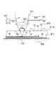
図2に示すように、半導体基板21の分断装置1には、半導体基板21を載置し、上下方向及び水平方向に搬送する図示しない移動機構を備えたステージ12と、半導体基板21をステージ12とともに液体に浸漬するための浸漬槽11とが設けられている。ここで、使用する液体は電子部品洗浄用の純度の高い水10である。
レーザ光Lを照射するレーザヘッド31は、レーザ光Lを集光する集光レンズ32を備えており、レーザ光Lを所定の焦点距離で集光させることができる。ここでは、レーザ光Lの集光点Pが水10の中に浸漬された半導体基板21の基板面21aから深さdの箇所に形成されるように設定されている。集光レンズ32のレーザ光Lの出射面32aは、レーザ光Lを照射するときには、水10に浸漬されている。したがって、レーザ光Lは空気を介さずに水10を介して基板面21aから半導体基板21内部へ照射される。
As shown in FIG. 2, in the
The
半導体基板21内部に改質層Kを形成するためには、まず、半導体基板21をステージ12に載置し、水10が貯留されている浸漬槽11の上方から浸漬する。このとき、基板面21aに付着している付着物22は、水10の浮力により浮かせて除去することができる。そのため、レーザ光Lの照射を妨げる付着物22を除去できるので、レーザ光Lの照射効率を向上させることができる。
次に、図1(A)に示す分断予定ラインDLの1つを、ウェハ検出用のレーザ光で走査し、図1(B)に示す外周端部21cを検出し、レーザ光Lの走査範囲を設定する。
続いて、図2に示すように、レーザヘッド31を分断予定ラインDLに沿って走査し(図中矢印F4方向)、レーザ光Lを基板面21aから半導体基板21内部へ照射することにより、レーザ光Lの集光点Pが走査された深さdの経路に、改質領域Kが適正に形成される。
In order to form the modified layer K inside the
Next, one of the planned dividing lines DL shown in FIG. 1A is scanned with the laser beam for wafer detection, the outer
Subsequently, as shown in FIG. 2, the
ここで、レーザ光Lの集光点Pの深さdを調整することにより、半導体基板21の厚さの範囲内で任意の深さに任意の層数の改質領域Kを形成することができる。例えば、厚さが比較的厚い場合は、その厚さ方向へ集光点Pを移動させて改質領域Kを厚さ方向に連続状、または複数箇所に形成することにより、半導体基板21の分断を容易にすることができる。
続いて、図7(B)に示した従来技術と同様に、半導体基板21の面内方向に応力を負荷することにより、改質領域Kを起点にして、基板厚さ方向にクラックを進展させて、半導体基板21を分断予定ラインDLに沿って容易に分断することができる。Here, by adjusting the depth d of the condensing point P of the laser light L, the modified region K having an arbitrary number of layers can be formed at an arbitrary depth within the thickness range of the
Subsequently, as in the prior art shown in FIG. 7B, stress is applied in the in-plane direction of the
次に、半導体基板21の基板面21aが空気に接している場合及び水10に接している場合のレーザ光Lの照射効率について説明する。ここで、レーザ光Lの照射効率とは、基板面21aで反射せずに半導体基板21内部に照射されたレーザ光Lの割合をいう。
レーザ光Lが基板面21aに垂直入射した場合の界面における反射率Rは次式で表される。
R={(1−ρ)/(1+ρ)}2(1)
ρ=n1/n2
n1:基板面21aと接している媒体(空気、水10)の屈折率、
n2:半導体基板21(シリコン)の屈折率
(1)式より、屈折率の差が小さい程、反射率Rは小さくなり、照射効率が向上する。ここで、空気の屈折率は1.0、水の屈折率は1.3、半導体基板21(シリコン)の屈折率は3.4であるから、(1)式より、基板面21aと接している媒体が空気の場合の反射率Rは約0.3、基板面21aと接している媒体が水10の場合の反射率Rは約0.2となる。したがって、レーザ光Lの照射効率は、基板面21aと接している媒体が空気の場合は約0.7、水10の場合は約0.8となる。つまり、水10を用いることにより、レーザ光の照射効率を約10%向上させることができる。
更に、上記同様に集光レンズ32の出射面32aにおけるレーザ光Lの反射も水10を用いる方が抑制されるため、水10を用いることによりレーザ光Lの照射効率を全体として大幅に向上させることができる。Next, the irradiation efficiency of the laser light L when the
The reflectance R at the interface when the laser light L is perpendicularly incident on the
R = {(1-ρ) / (1 + ρ)}2 (1)
ρ = n1 / n2
n1: Refractive index of the medium (air, water 10) in contact with the
n2: Refractive index of the semiconductor substrate 21 (silicon)
From equation (1), the smaller the difference in refractive index, the smaller the reflectance R, and the irradiation efficiency improves. Here, since the refractive index of air is 1.0, the refractive index of water is 1.3, and the refractive index of the semiconductor substrate 21 (silicon) is 3.4, it is in contact with the
Further, similarly to the above, since the reflection of the laser beam L at the
[第1実施形態の効果]
(1)第1実施形態に係る半導体基板21の分断装置1によれば、半導体基板21を水10に浸漬することにより、空気より屈折率が大きい液体である水10を、集光レンズ32の出射面32aと基板面21aとの間に供給して、レーザ光Lを半導体基板21の内部に集光点Pを合わせて基板面21aへ照射することができる。そのため、基板面21aが空気に接している場合に比べて、基板面21aにおけるレーザ光Lの屈折率の差を小さくできるので、基板面21aにおけるレーザ光Lの反射を抑制することができ、レーザ光Lの照射効率を向上することができる。
したがって、半導体基板21の基板面21aに反射防止膜の形成が不要で、半導体基板21内部へのレーザ光Lの入射を抑制することなく、レーザ光Lの反射を抑制し、照射効率を向上することができる半導体基板21の分断装置1を実現することができる。[Effect of the first embodiment]
(1) According to the
Therefore, it is not necessary to form an antireflection film on the
(2)水10が集光レンズ32の出射面32aと基板面21aとの間に充填されているため、レーザ光Lの光路に空気と水10との界面が存在せず、空気と水10との界面におけるレーザ光Lの反射がないので、レーザ光Lの照射効率を向上させることができる。(2) Since the
(3)半導体基板21の分断装置1を使用して、改質領域Kが形成された半導体基板21を、改質領域Kを起点にして、分断予定ラインDLに沿って厚さ方向に分断して半導体チップを得るため、レーザ光Lの照射効率を向上させることができ、半導体基板21を効率よく分断することができる。(3) Using the
[第2実施形態]
この発明に係る半導体基板の分断装置の第2実施形態について、図を参照して説明する。図3は、レーザ光の照射を行うときに、水10を浸漬槽11内で流動させる構成の説明図である。
なお、第1実施形態と同様の構成については、同じ符号を使用するとともに説明を省略する。[Second Embodiment]
A second embodiment of a semiconductor substrate cutting apparatus according to the present invention will be described with reference to the drawings. FIG. 3 is an explanatory diagram of a configuration in which the
In addition, about the structure similar to 1st Embodiment, while using the same code | symbol, description is abbreviate | omitted.
図3に示すように、浸漬槽11(図2)内には、水10を噴射して流動させる流動装置41が設けられており、水10は、分断予定ラインDLに沿って、レーザ光Lの走査方向と同じ方向(図中矢印F4方向)に流動される。この水10の流動の物理的作用により、レーザ光Lの照射を妨げる分断予定ラインDL上の付着物22を基板面21aから除去できる。ここで、水10の流動方向は、分断予定ラインDLと交差する方向でもよい。
また、水10を循環させて、フィルターなどにより付着物22を除去した清浄な水10を供給してもよい。この場合、常に付着物22の混入がない清浄な水10が供給されるため、基板面21aを更に清浄にすることができる。As shown in FIG. 3, a
Alternatively, the
[第2実施形態の効果]
水10が半導体基板21の基板面21aで流動するので、水10の流動の物理的作用により、レーザ光Lの照射を妨げる分断予定ラインDL上の付着物22を基板面21aから除去できる。そのため、レーザ光Lの照射を妨げる付着物22を除去できるので、レーザ光Lの照射効率を向上させることができる。[Effects of Second Embodiment]
Since the
[第3実施形態]
この発明に係る半導体基板の分断装置の第3実施形態について、図を参照して説明する。図4は、レーザ光の照射を行うときに、水10、または、半導体基板21に振動を付与する構成の説明図である。
なお、第1実施形態と同様の構成については、同じ符号を使用するとともに説明を省略する。[Third Embodiment]
A third embodiment of a semiconductor substrate cutting apparatus according to the present invention will be described with reference to the drawings. FIG. 4 is an explanatory diagram of a configuration in which vibration is applied to the
In addition, about the structure similar to 1st Embodiment, while using the same code | symbol, description is abbreviate | omitted.
図4に示すように、浸漬槽11(図2)には、水10を振動させる加振器51が設けられている。浸漬槽中の水に加振することにより、水10と半導体基板21の基板面21aとの間にせん断力が作用するため、付着物22を効率よく除去することができる。また、ステージ12に加振機構52を設け、半導体基板21に加振してもよい。半導体基板21に加振することによっても、水10と半導体基板21の基板面21aとの間にせん断力が作用するため、付着物22を効率よく除去することができる。 As shown in FIG. 4, the immersion tank 11 (FIG. 2) is provided with a
[第3実施形態の効果]
加振器51で浸漬部材11内の水10に振動を付与することにより、または、加振機構52で半導体基板21が加振されることにより、基板面21aと水10との間にせん断力が作用するため、付着物22を効率よく除去することができる。そのため、レーザ光Lの照射を妨げる付着物22を除去できるので、レーザ光Lの照射効率を向上させることができる。[Effect of the third embodiment]
A shearing force is applied between the
[第4実施形態]
この発明に係る半導体基板の分断装置の第4実施形態について、図を参照して説明する。図5は、レーザ光の照射を行うときに、水10に気泡を導入し、半導体基板21の基板面21aに吹き付ける構成の説明図である。
なお、第1実施形態と同様の構成については、同じ符号を使用するとともに説明を省略する。[Fourth Embodiment]
A fourth embodiment of a semiconductor substrate cutting apparatus according to the present invention will be described with reference to the drawings. FIG. 5 is an explanatory diagram of a configuration in which bubbles are introduced into the
In addition, about the structure similar to 1st Embodiment, while using the same code | symbol, description is abbreviate | omitted.
図5に示すように、浸漬槽11(図2)には、ノズル先端から水中に気泡62を導入し、基板面21aに吹き付けるバブラー61が設けられている。バブラー61を用いて気泡62を半導体基板21の基板面21aに吹き付けることにより、半導体基板21の基板面21aに付着している付着物22を気泡62の勢いにより基板面21aから剥離させ、気泡62の浮力により除去することができる。 As shown in FIG. 5, the immersion tank 11 (FIG. 2) is provided with a
[第4実施形態の効果]
気泡62を基板面21aに吹き付けるため、基板面21aに付着している付着物22を気泡62の勢いにより剥離させ、気泡62の浮力により除去することができる。そのため、レーザ光Lの照射を妨げる付着物22を除去できるので、レーザ光Lの照射効率を向上させることができる。[Effect of Fourth Embodiment]
Since the
[第5実施形態]
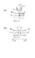
この発明に係る半導体基板の分断装置の第5実施形態について、図を参照して説明する。図6は、半導体基板21を、浸漬槽11内に貯留された、比重が異なりお互いに混合しない複数の液体に浸漬する構成の説明図である。
なお、第1実施形態と同様の構成については、同じ符号を使用するとともに説明を省略する。[Fifth Embodiment]
A fifth embodiment of a semiconductor substrate cutting apparatus according to the present invention will be described with reference to the drawings. FIG. 6 is an explanatory diagram of a configuration in which the
In addition, about the structure similar to 1st Embodiment, while using the same code | symbol, description is abbreviate | omitted.
図6に示すように、浸漬槽11には、比重の小さい方の液体として水が、比重の大きい方の液体として液状有機化合物70が貯留されている。両者はお互いに混合しないため、2層に分離して、水10が上層、液状有機化合物70が下層となっている。
上層の水10中では、レーザ光Lを照射し、半導体基板21内部に改質領域Kを形成する。その後、ステージ12を下降させて半導体基板21を液状有機化合物70中に浸漬させると、液状有機化合物70は水10より比重が大きいため浮力が増大するので、レーザ光Lの照射によって発生した付着物23を浮力で除去することができる
ここで、液状有機化合物70として、比重が1以上で水と混合しない、炭化水素系化合物、ハロゲン化炭化水素系化合物、アルコール系化合物、グリコール系化合物、エーテル系化合物、エステル系化合物、ケトン系化合物、硫黄化炭化水素系化合物及び窒化炭化水素系化合物などを用いることができる。As shown in FIG. 6, the
In the
[第5実施形態の効果]
水10中でレーザ光Lを照射するときには、レーザ光Lの反射を抑制し、レーザ光Lの照射効率を向上させることができる。その後、半導体基板21を液状有機化合物70中に移動させ、浸漬するため、レーザ光Lの照射によって基板面21aに発生した付着物22を浮力で除去することができる。[Effect of Fifth Embodiment]
When the laser beam L is irradiated in the
[その他の実施形態]
(1)浸漬槽11に供給する液体として、アルコールを用いることができる。この構成を使用した場合、浸漬後の乾燥時間を短くすることができるとともに、前述した第1〜4実施形態の効果を奏することができる。[Other Embodiments]
(1) Alcohol can be used as the liquid supplied to the
(2)浸漬槽11に供給する液体として、比重が1より大きい液状有機化合物を用いることができる。例えば、比重が1以上で水と混合しない、炭化水素系化合物、ハロゲン化炭化水素系化合物、アルコール系化合物、グリコール系化合物、エーテル系化合物、エステル系化合物、ケトン系化合物、硫黄化炭化水素系化合物及び窒化炭化水素系化合物などを用いることができる。
この構成を使用した場合、水10よりも比重が大きいため浮力が増大するので、基板面21aに付着した付着物22をより効果的に除去することができるとともに、前述した第1〜4実施形態の効果を奏することができる。(2) A liquid organic compound having a specific gravity greater than 1 can be used as the liquid supplied to the
When this configuration is used, buoyancy is increased because the specific gravity is greater than that of the
(3)浸漬槽11に供給する液体として、液体窒素または液体二酸化炭素を用いることができる。この構成を使用した場合、超臨界乾燥により表面張力の影響を少なくすることができるので、MEMSなどの可動部を固着させることがないとともに、前述した第1〜4実施形態の効果を奏することができる。
なお、浸漬槽11に供給する液体は、例えば、高屈折率水のように屈折率が空気よりも大きく、レーザ光Lを透過する液体であれば、上述したものに限定されるものではない。(3) Liquid nitrogen or liquid carbon dioxide can be used as the liquid supplied to the
The liquid supplied to the
(4)水10、または、上述した他の液体は、浸漬槽11に貯留せずに、半導体基板21の基板面21aの分断予定ラインDL上に必要量だけ載置、または、流動させてもよい。この構成を使用した場合には、使用する液体の量を少なくすることができ、廃液処理やコスト面で有利である。また、分断予定ラインDL近傍以外は液体で濡れないため、乾燥が容易であり、液体の表面張力で可動部が固着するおそれもない。
この構成を使用した場合にも、前述した第1〜4実施形態の効果を奏することができる。(4) Even if the
Even when this configuration is used, the effects of the first to fourth embodiments described above can be obtained.
(5)集光レンズ32の出射面32aは、液体に浸漬しなくてもよい。つまり、
半導体基板21は液体に浸漬されているが、集光レンズ32は、液体に浸漬しない状態で、液面の上方に配置し、レーザ光Lを照射する。この構成を使用した場合には、使用する液体の量を少なくすることができ、廃液処理やコスト面で有利である。また、レーザヘッド31及び集光レンズ32を液体に浸漬しないため、レーザヘッド31の構成部材の耐食性や気密性が要求されないため、簡単な構造にできる。(5) The
Although the
(6)半導体基板21には、シリコンのみで構成された半導体基板を用いたが、本発明の適用はこれに限られることはなく、例えば、酸化シリコンからなる酸化膜を半導体基板21の基板面21aに形成したものやSOI(Silicon On Insulator)のウェハについて適用することも可能である。(6) Although the semiconductor substrate made of only silicon is used as the
[各請求項と実施形態との対応関係]
出射面32aが請求項1に記載の出射部に、浸漬槽11が請求項3に記載の浸漬部材に、流動装置41が請求項4に記載の流動手段に、加振器51が請求項5に記載の振動手段に、加振機構52が請求項6に記載の加振手段に、バブラー61が請求項7に記載の気泡導入手段に、チップDevが請求項15に記載の半導体チップにそれぞれ対応する。[Correspondence between each claim and embodiment]
The
1 分断装置
10 水
11 浸漬槽(浸漬部材)
12 ステージ
20a ウェハ
21 半導体基板
21a 基板面
22 付着物
23 付着物
31 レーザヘッド
32 集光レンズ
32a 出射面(出射部)
41 流動装置(流動手段)
51 加振器(振動手段)
52 加振機構(加振手段)
61 バブラー(気泡導入手段)
70 液状有機化合物
CV 集光レンズ
Dev チップ(半導体チップ)
DL 分断予定ライン
K 改質領域
L レーザ光
P 集光点
W ウェハ1 Dividing
12
41 Flowing device (flowing means)
51 Exciter (vibration means)
52 Excitation mechanism (Excitation means)
61 Bubbler (bubble introduction means)
70 Liquid Organic Compound CV Condensing Lens Dev Chip (Semiconductor Chip)
DL line to be divided K modified region L laser beam P condensing point W wafer
Claims (11)
Translated fromJapanese空気より屈折率が大きい液体を前記レーザ光の出射部と前記基板面との間に供給することにより、前記液体を前記レーザ光の出射部と前記基板面との間に充填する供給手段を備え、
前記液体が前記レーザ光の出射部と前記基板面との間に充填された状態で、前記半導体基板の内部に集光点を合わせて前記レーザ光を照射し、
前記供給手段は、前記半導体基板を前記液体に浸漬する浸漬部材であり、
前記浸漬部材には、比重が異なり、お互いに混合しない異なる種類の液体が貯留されており、比重の小さい方の液体中で前記半導体基板に前記レーザ光の照射を行った後に、前記半導体基板を比重の大きい方の液体中に移動させて浸漬することを特徴とする半導体基板の分断装置。While moving the laser head that irradiates the laser beam along the planned dividing line for dividing the semiconductor substrate in the thickness direction relative to the substrate surface of the semiconductor substrate, a condensing point is formed inside the semiconductor substrate. In the semiconductor substrate cutting apparatus that irradiates the substrate surface with laser light so as to fit, and forms a modified region by multiphoton absorption at the condensing point,
Supply means for filling the liquid between the laser light emitting portion and the substrate surface by supplying a liquid having a refractive index larger than that of air between the laser light emitting portion and the substrate surface. ,
In a state where the liquid is filled between the laser light emitting portion and the substrate surface, the laser light is irradiatedwith the focusing point inside the semiconductor substrate,
The supply means is an immersion member that immerses the semiconductor substrate in the liquid,
The immersion member stores different types of liquids having different specific gravities and not mixed with each other, and after the semiconductor substrate is irradiated with the laser light in the liquid having a smaller specific gravity, the semiconductor substrate is A semiconductor substrate cutting apparatus, wherein the apparatus isimmersed in a liquid having a higher specific gravity .
前記比重の小さい方の液体は水であり、前記比重の大きい方の液体は液状有機化合物であることを特徴とする半導体基板の分断装置。In the semiconductor substrate cutting device according toclaim 1 ,
2. The semiconductor substrate cutting apparatus according to claim 1, wherein the liquid having the lower specific gravity is water, and the liquid having the higher specific gravity is a liquid organic compound.
前記比重の小さい方の液体は比重が1より大きい液状有機化合物であることを特徴とする半導体基板の分断装置。In the semiconductor substrate cutting device according toclaim 1 ,
2. The semiconductor substrate cutting apparatus according to claim 1, wherein the liquid having a smaller specific gravity is a liquid organic compound having a specific gravity greater than 1.
前記比重の小さい方の液体がアルコールであることを特徴とする半導体基板の分断装置。In the semiconductor substrate cutting device according toclaim 1 ,
A semiconductor substrate cutting device,wherein the liquidhaving a smaller specific gravity is alcohol.
前記比重の小さい方の液体が液体窒素であることを特徴とする半導体基板の分断装置。In the semiconductor substrate cutting device according toclaim 1 ,
A semiconductor substrate cutting apparatus,wherein the liquidhaving a smaller specific gravity is liquid nitrogen.
前記比重の小さい方の液体が液体二酸化炭素であることを特徴とする半導体基板の分断装置。In the semiconductor substrate cutting device according toclaim 1 ,
A semiconductor substrate cutting apparatus,wherein the liquidhaving a smaller specific gravity is liquid carbon dioxide.
前記比重の小さい方の液体を前記半導体基板の基板面で流動させる流動手段を備えたことを特徴とする半導体基板の分断装置。In the semiconductor substrate cutting device according toany one of claims 1 to 6 ,
A semiconductor substrate cutting apparatus, comprising: a flow unit configured to flowa liquidhaving a smaller specific gravity on the substrate surface of the semiconductor substrate.
前記比重の小さい方の液体に振動を付与する振動手段を備えたことを特徴とする半導体基板の分断装置。In the semiconductor substrate cutting device according toany one of claims 1 to 7 ,
A semiconductor substrate cutting apparatuscomprising a vibrating means for applying vibration tothe liquidhaving a smaller specific gravity .
前記半導体基板に加振する加振手段を備えたことを特徴とする半導体基板の分断装置。In the semiconductor substrate cutting device according toany one of claims 1 to 8 ,
A semiconductor substrate cutting apparatus comprising a vibrating means for vibrating the semiconductor substrate.
前記比重の小さい方の液体に気泡を導入し、その導入した気泡を前記半導体基板の基板面に吹き付ける気泡導入手段を備えたことを特徴とする半導体基板の分断装置。In the semiconductor substrate cutting device according toany one of claims 1 to 9 ,
A semiconductor substrate cutting device comprising bubble introducing means for introducing bubbles intothe liquidhaving the smaller specific gravity and blowing the introduced bubbles onto the substrate surface of the semiconductor substrate.
前記改質領域が形成された前記半導体基板を、前記前記改質領域を起点にして、前記分断予定ラインに沿って厚さ方向に分断して半導体チップを得ることを特徴とする半導体基板の分断方法。A semiconductor substrate cutting method using the semiconductor substrate cutting device according to any one ofclaims 1 to 10 ,
The semiconductor substrate on which the modified region is formed is divided in the thickness direction along the planned dividing line from the modified region as a starting point to obtain a semiconductor chip. Method.
Priority Applications (1)
| Application Number | Priority Date | Filing Date | Title |
|---|---|---|---|
| JP2005331213AJP4678281B2 (en) | 2005-11-16 | 2005-11-16 | Semiconductor substrate cutting device |
Applications Claiming Priority (1)
| Application Number | Priority Date | Filing Date | Title |
|---|---|---|---|
| JP2005331213AJP4678281B2 (en) | 2005-11-16 | 2005-11-16 | Semiconductor substrate cutting device |
Publications (2)
| Publication Number | Publication Date |
|---|---|
| JP2007136482A JP2007136482A (en) | 2007-06-07 |
| JP4678281B2true JP4678281B2 (en) | 2011-04-27 |
Family
ID=38199962
Family Applications (1)
| Application Number | Title | Priority Date | Filing Date |
|---|---|---|---|
| JP2005331213AExpired - Fee RelatedJP4678281B2 (en) | 2005-11-16 | 2005-11-16 | Semiconductor substrate cutting device |
Country Status (1)
| Country | Link |
|---|---|
| JP (1) | JP4678281B2 (en) |
Cited By (1)
| Publication number | Priority date | Publication date | Assignee | Title |
|---|---|---|---|---|
| CN108333651A (en)* | 2018-02-09 | 2018-07-27 | 上海理工大学 | A kind of manufacturing method of microlens array |
Families Citing this family (14)
| Publication number | Priority date | Publication date | Assignee | Title |
|---|---|---|---|---|
| JP4985291B2 (en)* | 2007-10-01 | 2012-07-25 | 株式会社デンソー | Wafer processing method |
| JP5710133B2 (en)* | 2010-03-16 | 2015-04-30 | 株式会社ディスコ | How to divide work |
| JP5983923B2 (en)* | 2012-08-01 | 2016-09-06 | 株式会社東京精密 | Laser dicing apparatus and method, and wafer processing method |
| JP2014212282A (en)* | 2013-04-22 | 2014-11-13 | 株式会社ディスコ | Processing method of wafer |
| JP6048713B2 (en)* | 2016-06-20 | 2016-12-21 | 株式会社東京精密 | Laser dicing apparatus and method |
| JP6044814B2 (en)* | 2016-08-03 | 2016-12-14 | 株式会社東京精密 | Laser dicing apparatus and method |
| JP6319640B2 (en)* | 2016-11-16 | 2018-05-09 | 株式会社東京精密 | Laser dicing apparatus and method |
| JP6968659B2 (en)* | 2017-10-25 | 2021-11-17 | 株式会社ディスコ | Laser processing equipment |
| JP6985102B2 (en)* | 2017-10-31 | 2021-12-22 | 株式会社ディスコ | Laser processing equipment |
| JP7080555B2 (en)* | 2018-03-16 | 2022-06-06 | 株式会社ディスコ | Wafer processing method |
| JP2020089912A (en)* | 2018-12-07 | 2020-06-11 | Dgshape株式会社 | Laser processing method and laser processing system |
| CN113498545A (en)* | 2019-03-07 | 2021-10-12 | 三菱电机株式会社 | Semiconductor chip manufacturing apparatus and semiconductor chip manufacturing method |
| JP7639390B2 (en)* | 2021-02-23 | 2025-03-05 | 株式会社デンソー | Semiconductor chip manufacturing method |
| DE102021109579B4 (en) | 2021-04-16 | 2023-03-23 | Trumpf Laser- Und Systemtechnik Gmbh | METHOD AND APPARATUS FOR MAKING MODIFICATIONS WITH A LASER BEAM IN A MATERIAL WITH A CURVED SURFACE |
Family Cites Families (5)
| Publication number | Priority date | Publication date | Assignee | Title |
|---|---|---|---|---|
| JP2000277480A (en)* | 1999-03-25 | 2000-10-06 | Kurita Water Ind Ltd | Semiconductor substrate cleaning method |
| JP4659300B2 (en)* | 2000-09-13 | 2011-03-30 | 浜松ホトニクス株式会社 | Laser processing method and semiconductor chip manufacturing method |
| JP3751970B2 (en)* | 2000-09-13 | 2006-03-08 | 浜松ホトニクス株式会社 | Laser processing equipment |
| JP3660294B2 (en)* | 2000-10-26 | 2005-06-15 | 株式会社東芝 | Manufacturing method of semiconductor device |
| JP2005057179A (en)* | 2003-08-07 | 2005-03-03 | Matsushita Electric Ind Co Ltd | Semiconductor device cleaning method |
- 2005
- 2005-11-16JPJP2005331213Apatent/JP4678281B2/ennot_activeExpired - Fee Related
Cited By (2)
| Publication number | Priority date | Publication date | Assignee | Title |
|---|---|---|---|---|
| CN108333651A (en)* | 2018-02-09 | 2018-07-27 | 上海理工大学 | A kind of manufacturing method of microlens array |
| CN108333651B (en)* | 2018-02-09 | 2019-07-19 | 上海理工大学 | Method and device for manufacturing a microlens array |
Also Published As
| Publication number | Publication date |
|---|---|
| JP2007136482A (en) | 2007-06-07 |
Similar Documents
| Publication | Publication Date | Title |
|---|---|---|
| JP4678281B2 (en) | Semiconductor substrate cutting device | |
| KR102214481B1 (en) | Methods for forming vias in glass substrates | |
| US6720522B2 (en) | Apparatus and method for laser beam machining, and method for manufacturing semiconductor devices using laser beam machining | |
| JP6223804B2 (en) | Wafer processing equipment | |
| TWI628150B (en) | Glass processing method | |
| TW201635363A (en) | Wafer producing method | |
| TW201639018A (en) | Wafer producing method | |
| JP2019175976A (en) | Element chip manufacturing method | |
| TW201639017A (en) | Wafer generation method | |
| JP2009010105A (en) | Wafer laser processing method | |
| JP2005150523A (en) | Wafer processing method | |
| CN108231676A (en) | The processing method of chip | |
| JP2006305586A (en) | Method for cutting plate-shaped body, and laser beam machining device | |
| JP4985291B2 (en) | Wafer processing method | |
| JP7012824B2 (en) | Polymer Resin Molded Compound-based substrate cutting method and its system | |
| JP2020066551A (en) | Manufacturing method of glass substrate | |
| KR20100070159A (en) | Th1e fabricating meth1od of wafer | |
| JP6512935B2 (en) | Laser processing method and laser processing apparatus | |
| KR102849495B1 (en) | Substrate processing method and substrate processing device | |
| JP2004106048A (en) | Processing method and processing apparatus | |
| JP5584560B2 (en) | Laser scribing method | |
| JP4060405B2 (en) | Manufacturing method of semiconductor wafer | |
| JP5089313B2 (en) | Substrate processing apparatus and processing method | |
| Shi et al. | Single & multi beam laser grooving process parameter development and die strength characterization for 40nm node low-K/ULK wafer | |
| KR100898913B1 (en) | Substrate Cleaning Method and Apparatus |
Legal Events
| Date | Code | Title | Description |
|---|---|---|---|
| A621 | Written request for application examination | Free format text:JAPANESE INTERMEDIATE CODE: A621 Effective date:20071128 | |
| A131 | Notification of reasons for refusal | Free format text:JAPANESE INTERMEDIATE CODE: A131 Effective date:20100112 | |
| A977 | Report on retrieval | Free format text:JAPANESE INTERMEDIATE CODE: A971007 Effective date:20100114 | |
| A521 | Request for written amendment filed | Free format text:JAPANESE INTERMEDIATE CODE: A523 Effective date:20100311 | |
| A131 | Notification of reasons for refusal | Free format text:JAPANESE INTERMEDIATE CODE: A131 Effective date:20100622 | |
| A521 | Request for written amendment filed | Free format text:JAPANESE INTERMEDIATE CODE: A523 Effective date:20100817 | |
| TRDD | Decision of grant or rejection written | ||
| A01 | Written decision to grant a patent or to grant a registration (utility model) | Free format text:JAPANESE INTERMEDIATE CODE: A01 Effective date:20110105 | |
| A01 | Written decision to grant a patent or to grant a registration (utility model) | Free format text:JAPANESE INTERMEDIATE CODE: A01 | |
| A61 | First payment of annual fees (during grant procedure) | Free format text:JAPANESE INTERMEDIATE CODE: A61 Effective date:20110118 | |
| R151 | Written notification of patent or utility model registration | Ref document number:4678281 Country of ref document:JP Free format text:JAPANESE INTERMEDIATE CODE: R151 | |
| FPAY | Renewal fee payment (event date is renewal date of database) | Free format text:PAYMENT UNTIL: 20140210 Year of fee payment:3 | |
| R250 | Receipt of annual fees | Free format text:JAPANESE INTERMEDIATE CODE: R250 | |
| R250 | Receipt of annual fees | Free format text:JAPANESE INTERMEDIATE CODE: R250 | |
| R250 | Receipt of annual fees | Free format text:JAPANESE INTERMEDIATE CODE: R250 | |
| R250 | Receipt of annual fees | Free format text:JAPANESE INTERMEDIATE CODE: R250 | |
| R250 | Receipt of annual fees | Free format text:JAPANESE INTERMEDIATE CODE: R250 | |
| R250 | Receipt of annual fees | Free format text:JAPANESE INTERMEDIATE CODE: R250 | |
| R250 | Receipt of annual fees | Free format text:JAPANESE INTERMEDIATE CODE: R250 | |
| LAPS | Cancellation because of no payment of annual fees |