JP4678243B2 - Power supply system - Google Patents
Power supply systemDownload PDFInfo
- Publication number
- JP4678243B2 JP4678243B2JP2005168023AJP2005168023AJP4678243B2JP 4678243 B2JP4678243 B2JP 4678243B2JP 2005168023 AJP2005168023 AJP 2005168023AJP 2005168023 AJP2005168023 AJP 2005168023AJP 4678243 B2JP4678243 B2JP 4678243B2
- Authority
- JP
- Japan
- Prior art keywords
- power
- vehicle
- commercial
- power generation
- power supply
- Prior art date
- Legal status (The legal status is an assumption and is not a legal conclusion. Google has not performed a legal analysis and makes no representation as to the accuracy of the status listed.)
- Expired - Fee Related
Links
Images


Classifications
- B—PERFORMING OPERATIONS; TRANSPORTING
- B60—VEHICLES IN GENERAL
- B60W—CONJOINT CONTROL OF VEHICLE SUB-UNITS OF DIFFERENT TYPE OR DIFFERENT FUNCTION; CONTROL SYSTEMS SPECIALLY ADAPTED FOR HYBRID VEHICLES; ROAD VEHICLE DRIVE CONTROL SYSTEMS FOR PURPOSES NOT RELATED TO THE CONTROL OF A PARTICULAR SUB-UNIT
- B60W20/00—Control systems specially adapted for hybrid vehicles
- B—PERFORMING OPERATIONS; TRANSPORTING
- B60—VEHICLES IN GENERAL
- B60K—ARRANGEMENT OR MOUNTING OF PROPULSION UNITS OR OF TRANSMISSIONS IN VEHICLES; ARRANGEMENT OR MOUNTING OF PLURAL DIVERSE PRIME-MOVERS IN VEHICLES; AUXILIARY DRIVES FOR VEHICLES; INSTRUMENTATION OR DASHBOARDS FOR VEHICLES; ARRANGEMENTS IN CONNECTION WITH COOLING, AIR INTAKE, GAS EXHAUST OR FUEL SUPPLY OF PROPULSION UNITS IN VEHICLES
- B60K6/00—Arrangement or mounting of plural diverse prime-movers for mutual or common propulsion, e.g. hybrid propulsion systems comprising electric motors and internal combustion engines
- B60K6/20—Arrangement or mounting of plural diverse prime-movers for mutual or common propulsion, e.g. hybrid propulsion systems comprising electric motors and internal combustion engines the prime-movers consisting of electric motors and internal combustion engines, e.g. HEVs
- B60K6/42—Arrangement or mounting of plural diverse prime-movers for mutual or common propulsion, e.g. hybrid propulsion systems comprising electric motors and internal combustion engines the prime-movers consisting of electric motors and internal combustion engines, e.g. HEVs characterised by the architecture of the hybrid electric vehicle
- B60K6/46—Series type
- B—PERFORMING OPERATIONS; TRANSPORTING
- B60—VEHICLES IN GENERAL
- B60L—PROPULSION OF ELECTRICALLY-PROPELLED VEHICLES; SUPPLYING ELECTRIC POWER FOR AUXILIARY EQUIPMENT OF ELECTRICALLY-PROPELLED VEHICLES; ELECTRODYNAMIC BRAKE SYSTEMS FOR VEHICLES IN GENERAL; MAGNETIC SUSPENSION OR LEVITATION FOR VEHICLES; MONITORING OPERATING VARIABLES OF ELECTRICALLY-PROPELLED VEHICLES; ELECTRIC SAFETY DEVICES FOR ELECTRICALLY-PROPELLED VEHICLES
- B60L50/00—Electric propulsion with power supplied within the vehicle
- B60L50/10—Electric propulsion with power supplied within the vehicle using propulsion power supplied by engine-driven generators, e.g. generators driven by combustion engines
- B60L50/16—Electric propulsion with power supplied within the vehicle using propulsion power supplied by engine-driven generators, e.g. generators driven by combustion engines with provision for separate direct mechanical propulsion
- B—PERFORMING OPERATIONS; TRANSPORTING
- B60—VEHICLES IN GENERAL
- B60L—PROPULSION OF ELECTRICALLY-PROPELLED VEHICLES; SUPPLYING ELECTRIC POWER FOR AUXILIARY EQUIPMENT OF ELECTRICALLY-PROPELLED VEHICLES; ELECTRODYNAMIC BRAKE SYSTEMS FOR VEHICLES IN GENERAL; MAGNETIC SUSPENSION OR LEVITATION FOR VEHICLES; MONITORING OPERATING VARIABLES OF ELECTRICALLY-PROPELLED VEHICLES; ELECTRIC SAFETY DEVICES FOR ELECTRICALLY-PROPELLED VEHICLES
- B60L50/00—Electric propulsion with power supplied within the vehicle
- B60L50/50—Electric propulsion with power supplied within the vehicle using propulsion power supplied by batteries or fuel cells
- B60L50/60—Electric propulsion with power supplied within the vehicle using propulsion power supplied by batteries or fuel cells using power supplied by batteries
- B60L50/61—Electric propulsion with power supplied within the vehicle using propulsion power supplied by batteries or fuel cells using power supplied by batteries by batteries charged by engine-driven generators, e.g. series hybrid electric vehicles
- B60L50/62—Electric propulsion with power supplied within the vehicle using propulsion power supplied by batteries or fuel cells using power supplied by batteries by batteries charged by engine-driven generators, e.g. series hybrid electric vehicles charged by low-power generators primarily intended to support the batteries, e.g. range extenders
- B—PERFORMING OPERATIONS; TRANSPORTING
- B60—VEHICLES IN GENERAL
- B60L—PROPULSION OF ELECTRICALLY-PROPELLED VEHICLES; SUPPLYING ELECTRIC POWER FOR AUXILIARY EQUIPMENT OF ELECTRICALLY-PROPELLED VEHICLES; ELECTRODYNAMIC BRAKE SYSTEMS FOR VEHICLES IN GENERAL; MAGNETIC SUSPENSION OR LEVITATION FOR VEHICLES; MONITORING OPERATING VARIABLES OF ELECTRICALLY-PROPELLED VEHICLES; ELECTRIC SAFETY DEVICES FOR ELECTRICALLY-PROPELLED VEHICLES
- B60L53/00—Methods of charging batteries, specially adapted for electric vehicles; Charging stations or on-board charging equipment therefor; Exchange of energy storage elements in electric vehicles
- B60L53/10—Methods of charging batteries, specially adapted for electric vehicles; Charging stations or on-board charging equipment therefor; Exchange of energy storage elements in electric vehicles characterised by the energy transfer between the charging station and the vehicle
- B60L53/14—Conductive energy transfer
- B—PERFORMING OPERATIONS; TRANSPORTING
- B60—VEHICLES IN GENERAL
- B60L—PROPULSION OF ELECTRICALLY-PROPELLED VEHICLES; SUPPLYING ELECTRIC POWER FOR AUXILIARY EQUIPMENT OF ELECTRICALLY-PROPELLED VEHICLES; ELECTRODYNAMIC BRAKE SYSTEMS FOR VEHICLES IN GENERAL; MAGNETIC SUSPENSION OR LEVITATION FOR VEHICLES; MONITORING OPERATING VARIABLES OF ELECTRICALLY-PROPELLED VEHICLES; ELECTRIC SAFETY DEVICES FOR ELECTRICALLY-PROPELLED VEHICLES
- B60L53/00—Methods of charging batteries, specially adapted for electric vehicles; Charging stations or on-board charging equipment therefor; Exchange of energy storage elements in electric vehicles
- B60L53/60—Monitoring or controlling charging stations
- B60L53/68—Off-site monitoring or control, e.g. remote control
- B—PERFORMING OPERATIONS; TRANSPORTING
- B60—VEHICLES IN GENERAL
- B60L—PROPULSION OF ELECTRICALLY-PROPELLED VEHICLES; SUPPLYING ELECTRIC POWER FOR AUXILIARY EQUIPMENT OF ELECTRICALLY-PROPELLED VEHICLES; ELECTRODYNAMIC BRAKE SYSTEMS FOR VEHICLES IN GENERAL; MAGNETIC SUSPENSION OR LEVITATION FOR VEHICLES; MONITORING OPERATING VARIABLES OF ELECTRICALLY-PROPELLED VEHICLES; ELECTRIC SAFETY DEVICES FOR ELECTRICALLY-PROPELLED VEHICLES
- B60L55/00—Arrangements for supplying energy stored within a vehicle to a power network, i.e. vehicle-to-grid [V2G] arrangements
- B—PERFORMING OPERATIONS; TRANSPORTING
- B60—VEHICLES IN GENERAL
- B60L—PROPULSION OF ELECTRICALLY-PROPELLED VEHICLES; SUPPLYING ELECTRIC POWER FOR AUXILIARY EQUIPMENT OF ELECTRICALLY-PROPELLED VEHICLES; ELECTRODYNAMIC BRAKE SYSTEMS FOR VEHICLES IN GENERAL; MAGNETIC SUSPENSION OR LEVITATION FOR VEHICLES; MONITORING OPERATING VARIABLES OF ELECTRICALLY-PROPELLED VEHICLES; ELECTRIC SAFETY DEVICES FOR ELECTRICALLY-PROPELLED VEHICLES
- B60L58/00—Methods or circuit arrangements for monitoring or controlling batteries or fuel cells, specially adapted for electric vehicles
- B60L58/40—Methods or circuit arrangements for monitoring or controlling batteries or fuel cells, specially adapted for electric vehicles for controlling a combination of batteries and fuel cells
- B—PERFORMING OPERATIONS; TRANSPORTING
- B60—VEHICLES IN GENERAL
- B60W—CONJOINT CONTROL OF VEHICLE SUB-UNITS OF DIFFERENT TYPE OR DIFFERENT FUNCTION; CONTROL SYSTEMS SPECIALLY ADAPTED FOR HYBRID VEHICLES; ROAD VEHICLE DRIVE CONTROL SYSTEMS FOR PURPOSES NOT RELATED TO THE CONTROL OF A PARTICULAR SUB-UNIT
- B60W10/00—Conjoint control of vehicle sub-units of different type or different function
- B60W10/04—Conjoint control of vehicle sub-units of different type or different function including control of propulsion units
- B60W10/08—Conjoint control of vehicle sub-units of different type or different function including control of propulsion units including control of electric propulsion units, e.g. motors or generators
- H—ELECTRICITY
- H02—GENERATION; CONVERSION OR DISTRIBUTION OF ELECTRIC POWER
- H02J—CIRCUIT ARRANGEMENTS OR SYSTEMS FOR SUPPLYING OR DISTRIBUTING ELECTRIC POWER; SYSTEMS FOR STORING ELECTRIC ENERGY
- H02J13/00—Circuit arrangements for providing remote indication of network conditions, e.g. an instantaneous record of the open or closed condition of each circuitbreaker in the network; Circuit arrangements for providing remote control of switching means in a power distribution network, e.g. switching in and out of current consumers by using a pulse code signal carried by the network
- H02J13/00006—Circuit arrangements for providing remote indication of network conditions, e.g. an instantaneous record of the open or closed condition of each circuitbreaker in the network; Circuit arrangements for providing remote control of switching means in a power distribution network, e.g. switching in and out of current consumers by using a pulse code signal carried by the network characterised by information or instructions transport means between the monitoring, controlling or managing units and monitored, controlled or operated power network element or electrical equipment
- H02J13/00007—Circuit arrangements for providing remote indication of network conditions, e.g. an instantaneous record of the open or closed condition of each circuitbreaker in the network; Circuit arrangements for providing remote control of switching means in a power distribution network, e.g. switching in and out of current consumers by using a pulse code signal carried by the network characterised by information or instructions transport means between the monitoring, controlling or managing units and monitored, controlled or operated power network element or electrical equipment using the power network as support for the transmission
- H02J13/00009—Circuit arrangements for providing remote indication of network conditions, e.g. an instantaneous record of the open or closed condition of each circuitbreaker in the network; Circuit arrangements for providing remote control of switching means in a power distribution network, e.g. switching in and out of current consumers by using a pulse code signal carried by the network characterised by information or instructions transport means between the monitoring, controlling or managing units and monitored, controlled or operated power network element or electrical equipment using the power network as support for the transmission using pulsed signals
- H—ELECTRICITY
- H02—GENERATION; CONVERSION OR DISTRIBUTION OF ELECTRIC POWER
- H02J—CIRCUIT ARRANGEMENTS OR SYSTEMS FOR SUPPLYING OR DISTRIBUTING ELECTRIC POWER; SYSTEMS FOR STORING ELECTRIC ENERGY
- H02J7/00—Circuit arrangements for charging or depolarising batteries or for supplying loads from batteries
- H02J7/14—Circuit arrangements for charging or depolarising batteries or for supplying loads from batteries for charging batteries from dynamo-electric generators driven at varying speed, e.g. on vehicle
- H02J7/1423—Circuit arrangements for charging or depolarising batteries or for supplying loads from batteries for charging batteries from dynamo-electric generators driven at varying speed, e.g. on vehicle with multiple batteries
- B—PERFORMING OPERATIONS; TRANSPORTING
- B60—VEHICLES IN GENERAL
- B60L—PROPULSION OF ELECTRICALLY-PROPELLED VEHICLES; SUPPLYING ELECTRIC POWER FOR AUXILIARY EQUIPMENT OF ELECTRICALLY-PROPELLED VEHICLES; ELECTRODYNAMIC BRAKE SYSTEMS FOR VEHICLES IN GENERAL; MAGNETIC SUSPENSION OR LEVITATION FOR VEHICLES; MONITORING OPERATING VARIABLES OF ELECTRICALLY-PROPELLED VEHICLES; ELECTRIC SAFETY DEVICES FOR ELECTRICALLY-PROPELLED VEHICLES
- B60L2210/00—Converter types
- B60L2210/20—AC to AC converters
- B—PERFORMING OPERATIONS; TRANSPORTING
- B60—VEHICLES IN GENERAL
- B60W—CONJOINT CONTROL OF VEHICLE SUB-UNITS OF DIFFERENT TYPE OR DIFFERENT FUNCTION; CONTROL SYSTEMS SPECIALLY ADAPTED FOR HYBRID VEHICLES; ROAD VEHICLE DRIVE CONTROL SYSTEMS FOR PURPOSES NOT RELATED TO THE CONTROL OF A PARTICULAR SUB-UNIT
- B60W2530/00—Input parameters relating to vehicle conditions or values, not covered by groups B60W2510/00 or B60W2520/00
- B60W2530/209—Fuel quantity remaining in tank
- H—ELECTRICITY
- H02—GENERATION; CONVERSION OR DISTRIBUTION OF ELECTRIC POWER
- H02J—CIRCUIT ARRANGEMENTS OR SYSTEMS FOR SUPPLYING OR DISTRIBUTING ELECTRIC POWER; SYSTEMS FOR STORING ELECTRIC ENERGY
- H02J3/00—Circuit arrangements for AC mains or AC distribution networks
- H02J3/38—Arrangements for parallely feeding a single network by two or more generators, converters or transformers
- Y—GENERAL TAGGING OF NEW TECHNOLOGICAL DEVELOPMENTS; GENERAL TAGGING OF CROSS-SECTIONAL TECHNOLOGIES SPANNING OVER SEVERAL SECTIONS OF THE IPC; TECHNICAL SUBJECTS COVERED BY FORMER USPC CROSS-REFERENCE ART COLLECTIONS [XRACs] AND DIGESTS
- Y02—TECHNOLOGIES OR APPLICATIONS FOR MITIGATION OR ADAPTATION AGAINST CLIMATE CHANGE
- Y02B—CLIMATE CHANGE MITIGATION TECHNOLOGIES RELATED TO BUILDINGS, e.g. HOUSING, HOUSE APPLIANCES OR RELATED END-USER APPLICATIONS
- Y02B90/00—Enabling technologies or technologies with a potential or indirect contribution to GHG emissions mitigation
- Y02B90/20—Smart grids as enabling technology in buildings sector
- Y—GENERAL TAGGING OF NEW TECHNOLOGICAL DEVELOPMENTS; GENERAL TAGGING OF CROSS-SECTIONAL TECHNOLOGIES SPANNING OVER SEVERAL SECTIONS OF THE IPC; TECHNICAL SUBJECTS COVERED BY FORMER USPC CROSS-REFERENCE ART COLLECTIONS [XRACs] AND DIGESTS
- Y02—TECHNOLOGIES OR APPLICATIONS FOR MITIGATION OR ADAPTATION AGAINST CLIMATE CHANGE
- Y02E—REDUCTION OF GREENHOUSE GAS [GHG] EMISSIONS, RELATED TO ENERGY GENERATION, TRANSMISSION OR DISTRIBUTION
- Y02E60/00—Enabling technologies; Technologies with a potential or indirect contribution to GHG emissions mitigation
- Y—GENERAL TAGGING OF NEW TECHNOLOGICAL DEVELOPMENTS; GENERAL TAGGING OF CROSS-SECTIONAL TECHNOLOGIES SPANNING OVER SEVERAL SECTIONS OF THE IPC; TECHNICAL SUBJECTS COVERED BY FORMER USPC CROSS-REFERENCE ART COLLECTIONS [XRACs] AND DIGESTS
- Y02—TECHNOLOGIES OR APPLICATIONS FOR MITIGATION OR ADAPTATION AGAINST CLIMATE CHANGE
- Y02T—CLIMATE CHANGE MITIGATION TECHNOLOGIES RELATED TO TRANSPORTATION
- Y02T10/00—Road transport of goods or passengers
- Y02T10/60—Other road transportation technologies with climate change mitigation effect
- Y02T10/62—Hybrid vehicles
- Y—GENERAL TAGGING OF NEW TECHNOLOGICAL DEVELOPMENTS; GENERAL TAGGING OF CROSS-SECTIONAL TECHNOLOGIES SPANNING OVER SEVERAL SECTIONS OF THE IPC; TECHNICAL SUBJECTS COVERED BY FORMER USPC CROSS-REFERENCE ART COLLECTIONS [XRACs] AND DIGESTS
- Y02—TECHNOLOGIES OR APPLICATIONS FOR MITIGATION OR ADAPTATION AGAINST CLIMATE CHANGE
- Y02T—CLIMATE CHANGE MITIGATION TECHNOLOGIES RELATED TO TRANSPORTATION
- Y02T10/00—Road transport of goods or passengers
- Y02T10/60—Other road transportation technologies with climate change mitigation effect
- Y02T10/70—Energy storage systems for electromobility, e.g. batteries
- Y—GENERAL TAGGING OF NEW TECHNOLOGICAL DEVELOPMENTS; GENERAL TAGGING OF CROSS-SECTIONAL TECHNOLOGIES SPANNING OVER SEVERAL SECTIONS OF THE IPC; TECHNICAL SUBJECTS COVERED BY FORMER USPC CROSS-REFERENCE ART COLLECTIONS [XRACs] AND DIGESTS
- Y02—TECHNOLOGIES OR APPLICATIONS FOR MITIGATION OR ADAPTATION AGAINST CLIMATE CHANGE
- Y02T—CLIMATE CHANGE MITIGATION TECHNOLOGIES RELATED TO TRANSPORTATION
- Y02T10/00—Road transport of goods or passengers
- Y02T10/60—Other road transportation technologies with climate change mitigation effect
- Y02T10/7072—Electromobility specific charging systems or methods for batteries, ultracapacitors, supercapacitors or double-layer capacitors
- Y—GENERAL TAGGING OF NEW TECHNOLOGICAL DEVELOPMENTS; GENERAL TAGGING OF CROSS-SECTIONAL TECHNOLOGIES SPANNING OVER SEVERAL SECTIONS OF THE IPC; TECHNICAL SUBJECTS COVERED BY FORMER USPC CROSS-REFERENCE ART COLLECTIONS [XRACs] AND DIGESTS
- Y02—TECHNOLOGIES OR APPLICATIONS FOR MITIGATION OR ADAPTATION AGAINST CLIMATE CHANGE
- Y02T—CLIMATE CHANGE MITIGATION TECHNOLOGIES RELATED TO TRANSPORTATION
- Y02T10/00—Road transport of goods or passengers
- Y02T10/60—Other road transportation technologies with climate change mitigation effect
- Y02T10/72—Electric energy management in electromobility
- Y—GENERAL TAGGING OF NEW TECHNOLOGICAL DEVELOPMENTS; GENERAL TAGGING OF CROSS-SECTIONAL TECHNOLOGIES SPANNING OVER SEVERAL SECTIONS OF THE IPC; TECHNICAL SUBJECTS COVERED BY FORMER USPC CROSS-REFERENCE ART COLLECTIONS [XRACs] AND DIGESTS
- Y02—TECHNOLOGIES OR APPLICATIONS FOR MITIGATION OR ADAPTATION AGAINST CLIMATE CHANGE
- Y02T—CLIMATE CHANGE MITIGATION TECHNOLOGIES RELATED TO TRANSPORTATION
- Y02T90/00—Enabling technologies or technologies with a potential or indirect contribution to GHG emissions mitigation
- Y02T90/10—Technologies relating to charging of electric vehicles
- Y02T90/12—Electric charging stations
- Y—GENERAL TAGGING OF NEW TECHNOLOGICAL DEVELOPMENTS; GENERAL TAGGING OF CROSS-SECTIONAL TECHNOLOGIES SPANNING OVER SEVERAL SECTIONS OF THE IPC; TECHNICAL SUBJECTS COVERED BY FORMER USPC CROSS-REFERENCE ART COLLECTIONS [XRACs] AND DIGESTS
- Y02—TECHNOLOGIES OR APPLICATIONS FOR MITIGATION OR ADAPTATION AGAINST CLIMATE CHANGE
- Y02T—CLIMATE CHANGE MITIGATION TECHNOLOGIES RELATED TO TRANSPORTATION
- Y02T90/00—Enabling technologies or technologies with a potential or indirect contribution to GHG emissions mitigation
- Y02T90/10—Technologies relating to charging of electric vehicles
- Y02T90/14—Plug-in electric vehicles
- Y—GENERAL TAGGING OF NEW TECHNOLOGICAL DEVELOPMENTS; GENERAL TAGGING OF CROSS-SECTIONAL TECHNOLOGIES SPANNING OVER SEVERAL SECTIONS OF THE IPC; TECHNICAL SUBJECTS COVERED BY FORMER USPC CROSS-REFERENCE ART COLLECTIONS [XRACs] AND DIGESTS
- Y02—TECHNOLOGIES OR APPLICATIONS FOR MITIGATION OR ADAPTATION AGAINST CLIMATE CHANGE
- Y02T—CLIMATE CHANGE MITIGATION TECHNOLOGIES RELATED TO TRANSPORTATION
- Y02T90/00—Enabling technologies or technologies with a potential or indirect contribution to GHG emissions mitigation
- Y02T90/10—Technologies relating to charging of electric vehicles
- Y02T90/16—Information or communication technologies improving the operation of electric vehicles
- Y02T90/167—Systems integrating technologies related to power network operation and communication or information technologies for supporting the interoperability of electric or hybrid vehicles, i.e. smartgrids as interface for battery charging of electric vehicles [EV] or hybrid vehicles [HEV]
- Y—GENERAL TAGGING OF NEW TECHNOLOGICAL DEVELOPMENTS; GENERAL TAGGING OF CROSS-SECTIONAL TECHNOLOGIES SPANNING OVER SEVERAL SECTIONS OF THE IPC; TECHNICAL SUBJECTS COVERED BY FORMER USPC CROSS-REFERENCE ART COLLECTIONS [XRACs] AND DIGESTS
- Y02—TECHNOLOGIES OR APPLICATIONS FOR MITIGATION OR ADAPTATION AGAINST CLIMATE CHANGE
- Y02T—CLIMATE CHANGE MITIGATION TECHNOLOGIES RELATED TO TRANSPORTATION
- Y02T90/00—Enabling technologies or technologies with a potential or indirect contribution to GHG emissions mitigation
- Y02T90/40—Application of hydrogen technology to transportation, e.g. using fuel cells
- Y—GENERAL TAGGING OF NEW TECHNOLOGICAL DEVELOPMENTS; GENERAL TAGGING OF CROSS-SECTIONAL TECHNOLOGIES SPANNING OVER SEVERAL SECTIONS OF THE IPC; TECHNICAL SUBJECTS COVERED BY FORMER USPC CROSS-REFERENCE ART COLLECTIONS [XRACs] AND DIGESTS
- Y04—INFORMATION OR COMMUNICATION TECHNOLOGIES HAVING AN IMPACT ON OTHER TECHNOLOGY AREAS
- Y04S—SYSTEMS INTEGRATING TECHNOLOGIES RELATED TO POWER NETWORK OPERATION, COMMUNICATION OR INFORMATION TECHNOLOGIES FOR IMPROVING THE ELECTRICAL POWER GENERATION, TRANSMISSION, DISTRIBUTION, MANAGEMENT OR USAGE, i.e. SMART GRIDS
- Y04S10/00—Systems supporting electrical power generation, transmission or distribution
- Y04S10/12—Monitoring or controlling equipment for energy generation units, e.g. distributed energy generation [DER] or load-side generation
- Y04S10/126—Monitoring or controlling equipment for energy generation units, e.g. distributed energy generation [DER] or load-side generation the energy generation units being or involving electric vehicles [EV] or hybrid vehicles [HEV], i.e. power aggregation of EV or HEV, vehicle to grid arrangements [V2G]
- Y—GENERAL TAGGING OF NEW TECHNOLOGICAL DEVELOPMENTS; GENERAL TAGGING OF CROSS-SECTIONAL TECHNOLOGIES SPANNING OVER SEVERAL SECTIONS OF THE IPC; TECHNICAL SUBJECTS COVERED BY FORMER USPC CROSS-REFERENCE ART COLLECTIONS [XRACs] AND DIGESTS
- Y04—INFORMATION OR COMMUNICATION TECHNOLOGIES HAVING AN IMPACT ON OTHER TECHNOLOGY AREAS
- Y04S—SYSTEMS INTEGRATING TECHNOLOGIES RELATED TO POWER NETWORK OPERATION, COMMUNICATION OR INFORMATION TECHNOLOGIES FOR IMPROVING THE ELECTRICAL POWER GENERATION, TRANSMISSION, DISTRIBUTION, MANAGEMENT OR USAGE, i.e. SMART GRIDS
- Y04S30/00—Systems supporting specific end-user applications in the sector of transportation
- Y04S30/10—Systems supporting the interoperability of electric or hybrid vehicles
- Y04S30/12—Remote or cooperative charging
- Y—GENERAL TAGGING OF NEW TECHNOLOGICAL DEVELOPMENTS; GENERAL TAGGING OF CROSS-SECTIONAL TECHNOLOGIES SPANNING OVER SEVERAL SECTIONS OF THE IPC; TECHNICAL SUBJECTS COVERED BY FORMER USPC CROSS-REFERENCE ART COLLECTIONS [XRACs] AND DIGESTS
- Y04—INFORMATION OR COMMUNICATION TECHNOLOGIES HAVING AN IMPACT ON OTHER TECHNOLOGY AREAS
- Y04S—SYSTEMS INTEGRATING TECHNOLOGIES RELATED TO POWER NETWORK OPERATION, COMMUNICATION OR INFORMATION TECHNOLOGIES FOR IMPROVING THE ELECTRICAL POWER GENERATION, TRANSMISSION, DISTRIBUTION, MANAGEMENT OR USAGE, i.e. SMART GRIDS
- Y04S40/00—Systems for electrical power generation, transmission, distribution or end-user application management characterised by the use of communication or information technologies, or communication or information technology specific aspects supporting them
- Y04S40/12—Systems for electrical power generation, transmission, distribution or end-user application management characterised by the use of communication or information technologies, or communication or information technology specific aspects supporting them characterised by data transport means between the monitoring, controlling or managing units and monitored, controlled or operated electrical equipment
- Y04S40/121—Systems for electrical power generation, transmission, distribution or end-user application management characterised by the use of communication or information technologies, or communication or information technology specific aspects supporting them characterised by data transport means between the monitoring, controlling or managing units and monitored, controlled or operated electrical equipment using the power network as support for the transmission
Landscapes
- Engineering & Computer Science (AREA)
- Power Engineering (AREA)
- Transportation (AREA)
- Mechanical Engineering (AREA)
- Chemical & Material Sciences (AREA)
- Combustion & Propulsion (AREA)
- Life Sciences & Earth Sciences (AREA)
- Sustainable Development (AREA)
- Sustainable Energy (AREA)
- Automation & Control Theory (AREA)
- Electric Propulsion And Braking For Vehicles (AREA)
- Supply And Distribution Of Alternating Current (AREA)
- Inverter Devices (AREA)
Description
Translated fromJapaneseこの発明は、電力供給システムに関し、特に、商用交流電力を発生して車両外部へ供給可能な車両を用いた電力供給システムに関する。 The present invention relates to a power supply system, and more particularly to a power supply system using a vehicle capable of generating commercial AC power and supplying it to the outside of the vehicle.
特許第2695083号公報(特許文献1)は、電気動力駆動の車両に使用される電動機駆動および動力処理装置を開示する。この電動機駆動および動力処理装置は、二次電池と、インバータIA,IBと、誘導電動機MA,MBと、制御ユニットとを備える。誘導電動機MA,MBは、Y結線された巻線CA,CBをそれぞれ含み、巻線CA,CBの中性点NA,NBには、EMIフィルターを介して入力/出力ポートが接続される。 Japanese Patent No. 2695083 (Patent Document 1) discloses an electric motor drive and power processing device used for an electric power drive vehicle. This electric motor drive and power processing device includes a secondary battery, inverters IA and IB, induction motors MA and MB, and a control unit. Induction motors MA and MB include Y-connected windings CA and CB, respectively, and input / output ports are connected to neutral points NA and NB of windings CA and CB via an EMI filter.
インバータIA,IBは、それぞれ誘導電動機MA,MBに対応して設けられ、それぞれ巻線CA,CBに接続される。そして、インバータIA,IBは、二次電池に並列に接続される。 Inverters IA and IB are provided corresponding to induction motors MA and MB, respectively, and are connected to windings CA and CB, respectively. Inverters IA and IB are connected in parallel to the secondary battery.
この電動機駆動および動力処理装置においては、インバータIA,IBは、中性点NA,NB間に正弦波の調整された交流電力を発生し、その発生した交流電力を入力/出力ポートに接続された外部装置に供給することができる(特許文献1参照)。
上述した特許第2695083号公報に開示された電動機駆動および動力処理装置は、交流電力を発生して外部装置へ供給可能な電源機能を備えている点で有用である。しかしながら、特許第2695083号公報では、発生した交流電力を商用電力系統に逆潮流したり、さらに、商用電力系統に接続された複数の車両からの電力供給を全体で管理する電力供給システムについては、特に考慮されていない。 The motor drive and power processing device disclosed in the above-mentioned Japanese Patent No. 2695083 is useful in that it has a power supply function that can generate AC power and supply it to an external device. However, in Japanese Patent No. 2695083, for the power supply system that reversely flows the generated AC power to the commercial power system or further manages the power supply from a plurality of vehicles connected to the commercial power system as a whole, Not specifically considered.
そこで、この発明は、かかる問題点を解決するためになされたものであり、その目的は、電源機能を備え、かつ、商用電力系統に接続された車両からの電力供給を管理可能な電力供給システムを提供することである。 Therefore, the present invention has been made to solve such problems, and an object of the present invention is to provide a power supply system having a power supply function and capable of managing power supply from a vehicle connected to a commercial power system. Is to provide.
この発明によれば、電力供給システムは、商用電力を発生して車両外部へ供給可能な少なくとも1台の車両と、少なくとも1台の車両に対応して設けられ、少なくとも1台の車両を商用電力系統と接続する少なくとも1つの接続手段と、商用電力系統に接続された少なくとも1台の車両による発電を管理する管理手段とを備える。少なくとも1台の車両の各々は、その車両に関する情報を管理手段へ出力する。管理手段は、その車両に関する情報に基づいて、その情報を出力した車両に対して商用電力の発生を要求する。そして、少なくとも1台の車両の各々は、管理手段からの要求に基づき商用電力を発生し、対応する接続手段を介して商用電力系統へ出力する。 According to this invention, the power supply system is provided corresponding to at least one vehicle capable of generating commercial power and supplying it to the outside of the vehicle, and at least one vehicle. And at least one connection means connected to the grid, and management means for managing power generation by at least one vehicle connected to the commercial power grid. Each of the at least one vehicle outputs information regarding the vehicle to the management means. Based on the information related to the vehicle, the management means requests the vehicle that has output the information to generate commercial power. Each of the at least one vehicle generates commercial power based on a request from the management unit and outputs the commercial power to the commercial power system via the corresponding connection unit.
この発明による電力供給システムにおいては、管理手段は、接続手段によって商用電力系統に接続された車両からその車両に関する情報を取得する。そして、管理手段は、その取得した車両に関する情報に基づいて、商用電力系統に接続され、かつ、電力供給能力を有する車両を探して発電を要求することができる。 In the power supply system according to the present invention, the management means acquires information related to the vehicle from the vehicle connected to the commercial power system by the connection means. And the management means can search for a vehicle that is connected to the commercial power system and has power supply capability based on the acquired information on the vehicle and can request power generation.
したがって、この発明による電力供給システムによれば、商用電力系統に電力不足が発生したとき、商用系統電力に接続され、かつ、電力供給能力を有する車両を用いて商用電力系統に電力を供給することができる。その結果、商用電力系統の電力不足を補うことができる。 Therefore, according to the power supply system of the present invention, when power shortage occurs in the commercial power system, power is supplied to the commercial power system using a vehicle connected to the commercial system power and having power supply capability. Can do. As a result, the power shortage of the commercial power system can be compensated.
好ましくは、少なくとも1台の車両の各々は、商用電力を発生する電力発生手段と、管理手段と通信を行なうための通信手段と、制御手段とを含む。制御手段は、通信手段を介して管理手段へその車両に関する情報を出力する。また、制御手段は、通信手段を介して受ける管理手段からの要求に基づき電力発生手段に対して商用電力の発生を指示する。 Preferably, each of the at least one vehicle includes power generation means for generating commercial power, communication means for communicating with management means, and control means. The control means outputs information relating to the vehicle to the management means via the communication means. The control unit instructs the power generation unit to generate commercial power based on a request from the management unit received via the communication unit.
さらに好ましくは、通信手段は、対応する接続手段および商用電力系統を介して管理手段と通信を行なう。 More preferably, the communication unit communicates with the management unit via the corresponding connection unit and the commercial power system.
この電力供給システムにおいては、通信手段は、対応する接続手段および商用電力系統を介して管理手段と通信を行なうので、通信専用ラインを別途設ける必要がない。したがって、この電力供給システムによれば、通信コストを低減することができる。 In this power supply system, since the communication means communicates with the management means via the corresponding connection means and the commercial power system, it is not necessary to provide a dedicated communication line. Therefore, according to this power supply system, the communication cost can be reduced.
好ましくは、電力発生手段は、内燃機関と、内燃機関の出力を用いて発電された電力を用いて商用電力を生成する電力生成部とから成る。車両に関する情報は、内燃機関を駆動するための燃料の残量を含み、管理手段は、残量が所定量以下になると、その車両に対して商用電力の発生の停止を指示する。 Preferably, the power generation means includes an internal combustion engine and a power generation unit that generates commercial power using power generated using the output of the internal combustion engine. The information about the vehicle includes the remaining amount of fuel for driving the internal combustion engine, and when the remaining amount falls below a predetermined amount, the management unit instructs the vehicle to stop generating commercial power.
この電力供給システムにおいては、車両は、たとえば内燃機関と電動機とを動力源とするハイブリッド自動車からなる。商用電力は、内燃機関の出力を用いて発電された電力を用いて生成される。ここで、管理手段は、内燃機関の燃料残量が所定量(たとえば給油ランプが点灯する量や利用者による設定量)以下になると、その車両に対して商用電力の発生の停止を指示するので、商用電力を供給していた車両において最小限の走行に必要な燃料が確保される。したがって、この電力供給システムによれば、少なくとも最寄の燃料スタンドまでの走行を確保することができる。 In this power supply system, the vehicle is a hybrid vehicle that uses, for example, an internal combustion engine and an electric motor as power sources. Commercial electric power is generated using electric power generated using the output of the internal combustion engine. Here, the management means instructs the vehicle to stop the generation of commercial power when the remaining amount of fuel in the internal combustion engine falls below a predetermined amount (for example, the amount that the fueling lamp is turned on or the amount set by the user). In addition, the fuel necessary for the minimum travel is ensured in the vehicle that has supplied commercial power. Therefore, according to this power supply system, it is possible to ensure traveling to at least the nearest fuel station.
好ましくは、電力発生手段は、燃料電池と、燃料電池から出力される電力を用いて商用電力を生成する電力生成部とから成る。車両に関する情報は、燃料電池の燃料の残量を含み、管理手段は、残量が所定量以下になると、その車両に対して商用電力の発生の停止を指示する。 Preferably, the power generation means includes a fuel cell and a power generation unit that generates commercial power using the power output from the fuel cell. The information about the vehicle includes the remaining amount of fuel in the fuel cell. When the remaining amount falls below a predetermined amount, the management unit instructs the vehicle to stop generating commercial power.
この電力供給システムにおいては、車両は、燃料電池を搭載した燃料電池車からなる。商用電力は、燃料電池から出力される電力を用いて生成される。ここで、管理手段は、燃料電池の燃料残量が所定量以下になると、その車両に対して商用電力の発生の停止を指示するので、商用電力を供給していた車両において最小限の走行に必要な燃料が確保される。したがって、この電力供給システムによっても、少なくとも最寄の燃料スタンドまでの走行を確保することができる。 In this power supply system, the vehicle is a fuel cell vehicle equipped with a fuel cell. Commercial power is generated using power output from the fuel cell. Here, the management means instructs the vehicle to stop the generation of the commercial power when the remaining amount of fuel in the fuel cell becomes a predetermined amount or less. Necessary fuel is secured. Therefore, this power supply system can also ensure traveling to at least the nearest fuel station.
好ましくは、商用電力系統には、複数台の車両が接続され、管理手段は、商用電力系統の電力不足量に応じて、複数台の車両の中から商用電力の供給を要求する車両を選択する。 Preferably, a plurality of vehicles are connected to the commercial power system, and the management unit selects a vehicle that requests supply of commercial power from the plurality of vehicles according to the power shortage amount of the commercial power system. .
この電力供給システムにおいては、管理手段は、複数台の車両の中から商用電力の供給を要求する車両の台数を制御することで、需要(電力不足量)に応じた電力を確保する。したがって、この電力供給システムによれば、車両からの電力供給量を適正化することができる。 In this power supply system, the management means secures power according to demand (power shortage) by controlling the number of vehicles that require supply of commercial power from among a plurality of vehicles. Therefore, according to this power supply system, the amount of power supplied from the vehicle can be optimized.
この発明によれば、電源機能を備え、かつ、商用電力系統に接続された車両からの電力供給を管理することができる。そして、商用電力系統に電力不足が発生したとき、商用系統電力に接続され、かつ、電力供給能力を有する車両を用いて商用電力系統に電力を供給することができる。その結果、商用電力系統の電力不足を補うことができる。 According to the present invention, it is possible to manage power supply from a vehicle having a power supply function and connected to a commercial power system. When power shortage occurs in the commercial power system, power can be supplied to the commercial power system using a vehicle that is connected to the commercial system power and has power supply capability. As a result, the power shortage of the commercial power system can be compensated.
以下、本発明の実施の形態について、図面を参照しながら詳細に説明する。なお、図中同一または相当部分には同一符号を付してその説明は繰返さない。 Hereinafter, embodiments of the present invention will be described in detail with reference to the drawings. In the drawings, the same or corresponding parts are denoted by the same reference numerals and description thereof will not be repeated.
図1は、この発明の実施の形態による電力供給システムの全体ブロック図である。図1を参照して、この電力供給システム1は、発電所10と、送電線20と、住宅30A,30Bと、車両40A,40Bと、管理サーバ50とを備える。 FIG. 1 is an overall block diagram of a power supply system according to an embodiment of the present invention. Referring to FIG. 1, this power supply system 1 includes a
発電所10は、商用電力を発生し、その発生した商用電力を送電線20へ出力する。住宅30A,30Bは、送電線20に接続され、送電線20から商用電力の供給を受ける。また、住宅30A,30Bは、車両40A,40Bによって発電された商用電力をそれぞれ車両40A,40Bから受け、その受けた商用電力を送電線20へ出力する。 The
車両40A,40Bは、ハイブリッド自動車である。車両40Aは、住宅30Aのコンセント32Aに接続される。そして、車両40Aは、後述の方法により商用電力を発生し、その発生した商用電力を住宅30Aのコンセント32Aへそれぞれ出力する。また、車両40Aは、コンセント32A、住宅30Aおよび送電線20を介して、送電線20に接続された管理サーバ50と通信を行なう。
具体的には、車両40Aは、住宅30Aのコンセント32Aに接続されているとき、車両40Aに関する情報を管理サーバ50へ出力する。車両40Aに関する情報は、管理サーバ50において車両40Aを識別するための車両番号や発電可能信号、発電量、燃料残量などの情報を含む。また、車両40Aは、当該車両40Aに対する起動指令や発電指令、停止指令などの各指令を管理サーバ50から受信し、受信した指令に応じた動作を行なう。 Specifically, the
車両40Bは、住宅30Bのコンセント32Bに接続される。車両40Bは、上述した車両40Aと同じ機能を有するので、その説明は繰返さない。
管理サーバ50は、送電線20に接続される。管理サーバ50は、この電力供給システム1に接続された車両40A,40Bと送電線20を介して通信を行ない、車両40A,40Bによる発電を管理する。具体的には、管理サーバ50は、電力不足が発生すると、電力供給システム1に接続されている車両40A,40Bを検出し、電力不足量に応じて車両40Aおよび/または車両40Bへ起動指令および発電指令を出力する。 The
また、管理サーバ50は、電力不足が解消したとき、あるいは、発電している車両の燃料残量が予め設定された基準値(たとえば給油ランプが点灯する量や利用者による設定量)以下になったことをその車両に関する情報に基づいて認識すると、発電を行なっている車両へ停止指令を出力する。 In addition, when the power shortage is resolved or the remaining amount of fuel of the vehicle that is generating power is lower than a predetermined reference value (for example, the amount that the fueling lamp is turned on or the amount that is set by the user), the
図2は、図1に示した車両40Aおよび住宅30Aの機能ブロック図である。なお、図1に示した車両40Bおよび住宅30Bの構成も、この図2で示される車両40Aおよび住宅30Aの構成と同じである。 FIG. 2 is a functional block diagram of
図2を参照して、車両40Aは、動力出力装置110と、リレー回路120と、モデム130と、通信ケーブル135と、ECU(Electronic Control Unit)140と、電圧計150と、電源ノード160と、接地ノード162と、コネクタ170と、AC出力ラインACL1,ACL2と、電力ラインLC1〜LC7とを含む。また、住宅30Aは、コンセント32Aと、電力計200と、警告灯210と、電力ラインLH1,LH2とを含む。 Referring to FIG. 2,
動力出力装置110は、AC出力ラインACL1,ACL2と接続される。リレー回路120は、電磁コイル122と、スイッチ124,126,128とから成る。電磁コイル122は、電力ラインLC2と接地ノード162との間に接続される。スイッチ124は、AC出力ラインACL1と電力ラインLC3との間に接続される。スイッチ126は、AC出力ラインACL2と電力ラインLC4との間に接続される。スイッチ128は、電力ラインLC5と接地ノード162との間に接続される。
モデム130は、電力ラインLC6,LC7を介してそれぞれ電力ラインLC3,LC4に接続される。また、モデム130は、通信ケーブル135を介してECU140と接続される。ECU140は、電力ラインLC1,LC2と接続される。そして、電力ラインLC3,LC4,LC1,LC5は、コネクタ170およびコンセント32Aを介してそれぞれ電力ラインLH1〜LH4と接続される。
電力計200は、電力ラインLH1,LH2と送電線20との間に配設される。警告灯210は、電力ラインLH3と電力ラインLH4との間に接続される。 The
動力出力装置110は、ECU140からのトルク指令に基づいて、このハイブリッド自動車の駆動力を発生する。また、動力出力装置110は、ECU140からの生成指令に基づいて商用交流電力を生成し、その生成した商用交流電力をAC出力ラインACL1,ACL2へ出力する。 The
リレー回路120の電磁コイル122は、ECU140から電力ラインLC2を介して電流が流されると、スイッチ124,126,128に作用する磁力を発生する。スイッチ124,126,128は、電磁コイル122からの磁力作用を受けて互いに連動して動作する。具体的には、スイッチ124,126,128は、電磁コイル122に電流が流されるとオンし、電磁コイル122に電流が流されていないときはオフする。 The
モデム130は、ECU140と送電線20に接続された管理サーバ50(図示せず、以下同じ。)との間で通信を行なう。すなわち、モデム130は、通信ケーブル135を介してECU140からデータを受けると、電力ラインLC6,LC7、電力ラインLC3,LC4、コネクタ170、コンセント32A、電力ラインLH1,LH2、電力計200および送電線20を介して、ECU140から受けたデータを管理サーバ50へ出力する。また、モデム130は、送電線20、電力計200、電力ラインLH1,LH2、コンセント32A、コネクタ170、電力ラインLC3,LC4および電力ラインLC6,LC7を介して管理サーバ50から受けたデータを通信ケーブル135を介してECU140へ出力する。
ECU140は、コネクタ170がコンセント32Aに接続されておらず、車両が走行可能なとき、動力出力装置110に含まれるモータジェネレータ(後述)のトルク指令を生成し、その生成したトルク指令を動力出力装置110へ出力する。
また、ECU140は、コネクタ170がコンセント32Aに接続されているとき、管理サーバ50からモデム130を経由して起動指令を受信すると、この車両40Aを起動する。なお、車両40Aの起動は、たとえば、イグニッションスイッチがON位置(ハイブリッドシステム全体に通電が行なわれる。)に回動されたものとされることにより行なわれる。 In addition, when the
さらに、ECU140は、管理サーバ50からモデム130を経由して発電指令を受信すると、電力ラインLC2へ電流を供給し、リレー回路120をオンする。そして、ECU140は、電力ラインLC1の電圧レベルに応じて論理レベルが決定される発電許可信号/ENがL(論理ロー)レベルになると、発電指令によって要求された商用交流電力の生成指令を動力出力装置110へ出力する。すなわち、リレー128がオンされたとき、コネクタ170がコンセント32Aと正常に接続されていれば、電源ノード160から電力ラインLC1、警告灯210、電力ラインLC5およびリレー128を介して接地ノード162への電路が形成されるため、電力ラインLC1の電圧レベルが低下し、発電許可信号/ENはLレベルとなる。 Further, when
また、さらに、ECU140は、管理サーバ50からモデム130を経由して停止指令を受信すると、商用交流電力の生成指令の動力出力装置110への出力を停止する。また、さらに、ECU140は、管理サーバ50からモデム130を経由して起動指令を受信すると、この車両に関する情報(車両番号や発電可能信号、発電量、燃料残量など)をモデム130を経由して管理サーバ50へ出力する。 Furthermore, when
電圧計150は、電力ラインLC6,LC7の電圧、すなわち電力ラインLC6,LC7と電気的に接続されている送電線20の電圧Voを検出し、その検出した電圧VoをECU140へ出力する。
電力計200は、車両40Aから送電線20に供給される電力量を検出し、その検出した電力量を住宅30A内において表示する。警告灯210は、コンセント32Aにコネクタ170が正常に接続されているときに車両40Aのリレー回路120がオンされると、電源ノード160から接地ノード162への電路が形成されることにより点灯する。
図3は、図2に示したECU140の機能ブロック図である。図3を参照して、ECU140は、データ入力部310と、起動制御部320と、発電制御部330と、残量演算部340と、データ出力部350とから成る。 FIG. 3 is a functional block diagram of
データ入力部310は、電力会社の管理サーバ50から送電線20を介して当該車両に送信された起動指令ST、発電指令GEまたは停止指令STPの各種指令をモデム130を経由して受信する。そして、データ入力部310は、起動指令STを受信すると、その旨を起動制御部320へ通知する。また、データ入力部310は、発電指令GEを受信すると、その発電指令GEによって指示された発電量を発電制御部330へ通知する。さらに、データ入力部310は、停止指令STPを受信すると、その旨を起動制御部320および発電制御部330へ通知する。 The
起動制御部320は、管理サーバ50から起動指令STを受信した旨の通知をデータ入力部310から受けると、発電許可信号/ENに基づいて、コネクタ170がコンセント32Aに正常に接続されているか否かを判定する。起動制御部320は、発電許可信号/ENがLレベルであり、コネクタ170がコンセント32Aに正常に接続されていると判定すると、車両40Aを起動する。そして、車両40Aが起動されると、起動制御部320は、予め車両40Aに割り当てられている車両IDおよび発電可能信号GPENをデータ出力部350へ出力する。 Upon receiving a notification from the
また、起動制御部320は、管理サーバ50から停止指令STPを受信した旨の通知をデータ入力部310から受けると、車両40Aを停止する。なお、車両40Aの停止は、たとえば、イグニッションスイッチがOFF位置に回動されたものとされることにより行なわれる。 In addition, upon receiving a notification from the
発電制御部330は、発電指令GEによって指示された発電量を受けると、電圧計150からの電圧Voに基づいて商用系統電力に同期した同期信号SYNCを生成する。また、発電制御部330は、その生成した同期信号SYNCに同期し、かつ、指示された発電量に応じた電流指令IACを生成する。そして、発電制御部330は、その生成した同期信号SYNCおよび電流指令IACを動力出力装置110へ出力する。 When the power
さらに、発電制御部330は、動力出力装置110によって発電された発電量を検出または演算し、その発電量OUTをデータ出力部350へ出力する。また、さらに、発電制御部330は、管理サーバ50から停止指令STPを受信した旨の通知をデータ入力部310から受けると、同期信号SYNCおよび電流指令IACの動力出力装置110への出力を停止する。 Further, the power
残量演算部340は、動力出力装置110の燃料タンク(後述)から受ける信号FUELに基づいて、今後発電可能な残量RE(kwh)を算出し、その算出した残量REをデータ出力部350へ出力する。 Based on a signal FUEL received from a fuel tank (described later) of the
データ出力部350は、起動制御部320から受ける車両IDおよび発電可能信号GPEN、発電制御部330から受ける発電量OUT、および残量演算部340から受ける残量REをモデム130へ出力する。そして、モデム130に出力された各データは、モデム130から送電線20を介して電力会社の管理サーバ50へ送信される。 The
図4は、図1に示した管理サーバ50の機能ブロック図である。図4を参照して、管理サーバ50は、データ入力部410と、電力不足判定部420と、制御部430と、発電指令部440と、データ出力部450とを含む。 FIG. 4 is a functional block diagram of the
データ入力部410は、車両ID、発電許可信号GPEN、発電量OUTおよび残量REを含む車両情報を車両40A,40Bから送電線20を介して受信し、その受信した車両情報を制御部430へ出力する。 The
電力不足判定部420は、発電所10の発電能力および発電量に基づいて、電力不足が発生しているか否かを判定する。そして、電力不足判定部420は、電力不足が発生していると判定すると、電力不足量を制御部430へ通知する。 The power
制御部430は、電力不足判定部420から電力不足量を受けると、データ入力部410から受ける車両IDおよび発電許可信号GPENに基づいて、その時点で発電可能な車両を検出する。そして、制御部430は、その電力不足量に応じて、検出された発電可能な車両の中から発電を要求する車両を選択し、その選択された車両に対する起動指令STを生成する。発電を要求する車両の選択基準としては、たとえば各車両から受ける残量REの多い車両から選択することができる。そして、制御部430は、その生成した起動指令STをデータ出力部450へ出力する。 When
また、制御部430は、発電を要求する車両に対応する発電量OUTおよび残量REに基づいて、その車両に対する発電指令GE(発電量を含む)の生成を指示する信号を発電指令部440へ出力する。さらに、制御部430は、電力不足が解消したとき、または、車両ごとに予め設定された基準値よりも残量REが下回ったとき、停止指令STPを生成し、その生成した停止指令STPをデータ出力部450へ出力する。 Further, based on the power generation amount OUT and the remaining amount RE corresponding to the vehicle that requests power generation, the
発電指令部440は、制御部430からの指示に応じて、発電量OUTおよび残量REに基づき発電指令GEを生成し、その生成した発電指令GEをデータ出力部450へ出力する。 The power
データ出力部450は、制御部430から受ける起動指令STまたは停止指令STP、および発電指令部440から受ける発電指令GEを送電線20を介して対応する車両へ出力する。
図5は、図2に示した動力出力装置110の全体ブロック図である。図5を参照して、
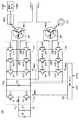
動力出力装置110は、バッテリBと、昇圧コンバータ510と、インバータ520,530と、MG−ECU540と、モータジェネレータMG1,MG2と、エンジンENGと、燃料タンクTANKと、駆動輪550と、コンデンサC1,C2と、電源ラインPL1,PL2と、接地ラインSLとから成る。FIG. 5 is an overall block diagram of the
バッテリBは、電源ラインPL1と接地ラインSLとの間に接続される。コンデンサC1は、電源ラインPL1と接地ラインSLとの間にバッテリBに並列に接続される。昇圧コンバータ510は、リアクトルLと、パワートランジスタQ1,Q2と、ダイオードD1,D2とを含む。パワートランジスタQ1,Q2は、電源ラインPL2と接地ラインSLとの間に直列に接続される。ダイオードD1,D2は、それぞれパワートランジスタQ1,Q2に逆並列に接続される。リアクトルLは、パワートランジスタQ1,Q2の接続点と電源ラインPL1との間に接続される。 Battery B is connected between power supply line PL1 and ground line SL. Capacitor C1 is connected in parallel to battery B between power supply line PL1 and ground line SL.
コンデンサC2は、電源ラインPL1と接地ラインSLとの間に接続される。インバータ520は、U相アーム522、V相アーム524およびW相アーム526を含む。U相アーム522、V相アーム524およびW相アーム526は、電源ラインPL2と接地ラインSLとの間に並列に接続される。U相アーム522は、直列に接続されたパワートランジスタQ11,Q12からなり、V相アーム524は、直列に接続されたパワートランジスタQ13,Q14からなり、W相アーム526は、直列に接続されたパワートランジスタQ15,Q16からなる。ダイオードD11〜D16は、それぞれパワートランジスタQ11〜Q16に逆並列に接続される。U,V,W各相アームにおける各パワートランジスタの接続点は、モータジェネレータMG1の中性点N1と異なるコイル端にそれぞれ接続される。 Capacitor C2 is connected between power supply line PL1 and ground line SL.
インバータ530は、U相アーム532、V相アーム534およびW相アーム536を含む。インバータ530も、インバータ520と同様の構成からなる。そして、U,V,W各相アームにおける各パワートランジスタの接続点は、モータジェネレータMG2の中性点N2と異なるコイル端にそれぞれ接続される。
エンジンENGは、連結部材を介してモータジェネレータMG1と連結される。駆動輪550は、駆動軸を介してモータジェネレータMG2と連結される。そして、AC出力ラインACL1,ACL2は、モータジェネレータMG1の中性点N1およびモータジェネレータMG2の中性点N2にそれぞれ接続される。 Engine ENG is coupled to motor generator MG1 via a coupling member.
バッテリBは、直流電源であり、たとえば、ニッケル水素やリチウムイオン等の二次電池からなる。バッテリBは、直流電圧を発生して電源ラインPL1へ出力する。また、バッテリBは、昇圧コンバータ510によって充電される。コンデンサC1は、電源ラインPL1と接地ラインSLとの間の電圧変動を平滑化する。 The battery B is a direct current power source, and is composed of, for example, a secondary battery such as nickel metal hydride or lithium ion. Battery B generates a DC voltage and outputs it to power supply line PL1. Battery B is charged by
昇圧コンバータ510は、MG−ECU540からの信号PWCに基づいて、バッテリBから受ける直流電圧をリアクトルLを用いて昇圧し、その昇圧した昇圧電圧を電源ラインPL2に供給する。また、昇圧コンバータ510は、MG−ECU540からの信号PWCに基づいて、電源ラインPL2の電圧を降圧してバッテリBを充電する。コンデンサC2は、電源ラインPL2と接地ラインSLとの間の電圧変動を平滑化する。
インバータ520は、MG−ECU540からの信号PWM1に基づいて、電源ラインPL2から受ける直流電圧を3相交流電圧に変換してモータジェネレータMG1へ出力する。また、インバータ520は、エンジンENGからの出力を受けてモータジェネレータMG1が発電した3相交流電圧を直流電圧に変換して電源ラインPL2へ出力する。
インバータ530は、MG−ECU540からの信号PWM2に基づいて、電源ラインPL2から受ける直流電圧を3相交流電圧に変換してモータジェネレータMG2へ出力する。また、インバータ530は、車両の回生制動時、モータジェネレータMG2が発電した3相交流電圧を直流電圧に変換して電源ラインPL2へ出力する。
ここで、MG−ECU540がECU140(図示せず、以下同じ。)から電流指令IACおよび同期信号SYNCを受けているとき、インバータ520,530は、それぞれMG−ECU540からの信号PWM1,PWM2に基づいて、モータジェネレータMG1,MG2の中性点N1,N2間に商用交流電力を発生させるように中性点N1,N2の電位をそれぞれ制御する。 Here, when MG-
モータジェネレータMG1,MG2は、3相交流電動発電機であり、たとえば3相交流同期電動発電機からなる。モータジェネレータMG1は、エンジンENGからの出力を用いて3相交流電圧を発生し、その発生した3相交流電圧をインバータ520へ出力する。また、モータジェネレータMG1は、インバータ520から受ける3相交流電圧によって駆動力を発生し、エンジンENGの始動を行なう。モータジェネレータMG2は、インバータ530から受ける3相交流電圧によって車両の駆動トルクを発生する。また、モータジェネレータMG2は、車両の回生制動時、3相交流電圧を発生してインバータ530へ出力する。 Motor generators MG1 and MG2 are three-phase AC motor generators, for example, three-phase AC synchronous motor generators. Motor generator MG1 generates a three-phase AC voltage using the output from engine ENG, and outputs the generated three-phase AC voltage to
エンジンENGは、燃料タンクTANKからの燃料を用いて動力を生成し、その生成した動力によってモータジェネレータMG1を駆動する。また、エンジンENGからの動力は、図示されない動力分割機構を介して駆動輪550へも出力される。燃料タンクTANKは、エンジンENGに燃料を供給する。また、燃料タンクTANKは、タンク内の燃料残量を示す信号FUELをECU140へ出力する。 Engine ENG generates power using fuel from fuel tank TANK, and drives motor generator MG1 with the generated power. Power from engine ENG is also output to drive
MG−ECU540は、モータジェネレータMG1,MG2のトルク指令値およびモータ回転数、バッテリBの電圧ならびに電源ラインPL2の電圧に基づいて、昇圧コンバータ510を駆動するための信号PWCを生成し、その生成した信号PWCを昇圧コンバータ510へ出力する。なお、モータ回転数ならびにバッテリBおよび電源ラインPL2の電圧は、図示されない各センサによって検出される。 MG-
また、MG−ECU540は、電源ラインPL2の電圧ならびにモータジェネレータMG1の各相電流およびトルク指令値に基づいて、モータジェネレータMG1を駆動するための信号PWM1を生成し、その生成した信号PWM1をインバータ520へ出力する。さらに、MG−ECU540は、電源ラインPL2の電圧ならびにモータジェネレータMG2の各相電流およびトルク指令値に基づいて、モータジェネレータMG2を駆動するための信号PWM2を生成し、その生成した信号PWM2をインバータ530へ出力する。なお、モータジェネレータMG1,MG2の各相電流は、図示されない電流センサによって検出される。 MG-
また、さらに、MG−ECU540は、ECU140から同期信号SYNCおよび電流指令IACを受けると、その受けた同期信号SYNCに同期し、かつ、電流指令IACに応じた商用交流電力がモータジェネレータMG1,MG2の中性点N1,N2間に発生するように、信号PWM1,PWM2を生成する。 Further, when MG-
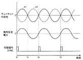
図6は、図5に示したモータジェネレータMG1,MG2の中性点N1,N2間に商用交流電力が発生しているときのインバータ520,530のデューティーの総和および商用交流電力の波形図である。図6を参照して、曲線k1は、インバータ520のスイッチング制御におけるデューティーの総和の変化を示し、曲線k2は、インバータ530のスイッチング制御におけるデューティーの総和の変化を示す。ここで、デューティーの総和とは、各インバータにおける上アームのオンデューティーから下アームのオンデューティーを減算したものである。したがって、デューティーの総和が正のときは、対応するモータジェネレータの中性点電位がインバータ入力電圧(電源ラインPL2の電圧)の中間電位よりも高くなることを示し、デューティーの総和が負のときは、中性点電位がインバータ入力電圧の中間電位よりも低くなることを示す。 FIG. 6 is a waveform diagram of the duty sum of
MG−ECU540は、中性点N1,N2間に商用交流電力を発生させるとき、インバータ520のデューティーの総和を同期信号SYNCに同期して商用電源周波数で変動する曲線k1に従って変化させ、インバータ530のデューティーの総和を曲線k2に従って変化させる。ここで、曲線k2は、曲線k1の位相を反転した曲線である。すなわち、インバータ530のデューティーの総和は、インバータ520のデューティーの総和が変化する位相を反転した位相で周期的に変えられる。 When MG-
そうすると、時刻t0〜t1においては、中性点N1の電位は、インバータ入力電圧の中間電位よりも高くなり、中性点N2の電位は、その中間電位よりも低くなり、中性点N1,N2間に正側の交流電圧が発生する。時刻t0〜t1に続く時刻t1〜t2においては、中性点N1の電位は、インバータ入力電圧の中間電位よりも低くなり、中性点N2の電位は、その中間電位よりも高くなり、中性点N1,N2間に負側の交流電圧が発生する。 Then, at time t0 to t1, the potential at the neutral point N1 becomes higher than the intermediate potential of the inverter input voltage, the potential at the neutral point N2 becomes lower than the intermediate potential, and the neutral points N1, N2 A positive AC voltage is generated between them. At time t1 to t2 following time t0 to t1, the potential at the neutral point N1 is lower than the intermediate potential of the inverter input voltage, and the potential at the neutral point N2 is higher than the intermediate potential, A negative AC voltage is generated between the points N1 and N2.
このようにして、中性点N1,N2間に商用電源周波数を有する交流電圧が発生する。そして、ECU140から受ける電流指令IACに応じて曲線k1,k2の振幅を制御することにより、商用電源周波数を有する商用交流電力を中性点N1,N2間に発生させることができる。 In this way, an AC voltage having a commercial power supply frequency is generated between the neutral points N1 and N2. Then, by controlling the amplitudes of curves k1 and k2 according to current command IAC received from
なお、この動力出力装置110では、モータジェネレータMG1,MG2を駆動しつつ中性点N1,N2間に商用交流電力を発生することができる。そこで、エンジンENGと連結されたモータジェネレータMG1を回生駆動(発電)し、駆動輪550と連結されたモータジェネレータMG2を反力制御(力行駆動)しつつ、商用交流電力を発生して送電線20に供給することができる。 In this
以上のように、この実施の形態によれば、管理サーバ50は、住宅30A,30Bを介して商用電力系統(送電線20)に接続された車両40A,40Bからその車両に関する情報を取得する。そして、管理サーバ50は、その取得した車両に関する情報に基づいて、電力供給能力を有する車両40A,40Bを探して発電を要求することができる。したがって、商用電力系統に電力不足が発生したとき、車両40A,40Bを用いて商用電力系統に電力を供給することができる。その結果、発電所10の電力供給不足を補うことができる。 As described above, according to this embodiment, the
また、モデム130は、対応する住宅30A(または30B)および送電線20を介して管理サーバ50と通信を行なうので、通信専用ラインを別途設ける必要がない。したがって、通信コストを低減することができる。 Moreover, since the
さらに、ハイブリッド自動車である車両40A,40Bは、内燃機関の出力を用いて商用交流電力を生成する。そして、管理サーバ50は、車両から受ける残量REが基準値以下になると、その車両に対して商用交流電力の発生の停止を指示する。したがって、商用交流電力を供給していた車両において最小限の走行に必要な燃料が確保され、少なくとも最寄の燃料スタンドまでの走行を確保することができる。 Furthermore, the
なお、上記の実施の形態においては、車両40A,40Bは、ハイブリッド自動車とし、ハイブリッド自動車に搭載される2台のモータジェネレータMG1,MG2の中性点N1,N2間に商用交流電力を発生させるものとしたが、この発明は、商用交流電力を発生するための専用のインバータを備えた電源システムにも適用可能である。 In the above embodiment,
また、上記の実施の形態においては、車両40A,40Bは、ハイブリッド自動車としたが、車両40A,40Bは、燃料電池車であってもよい。 In the above embodiment, the
図7は、図1に示した車両40A,40Bが燃料電池車の場合の動力出力装置110Aの全体ブロック図である。図7を参照して、動力出力装置110Aは、燃料電池FCと、水素タンク610と、昇圧コンバータ510と、インバータ530,620と、モータジェネレータMG2と、駆動輪550とから成る。 FIG. 7 is an overall block diagram of a
燃料電池FCは、水素タンク610から供給される水素と酸化剤との化学反応によって発生する化学反応エネルギーから電気エネルギーを得る直流電力発電電池である。そして、燃料電池FCは、発生した直流電力を昇圧コンバータ510へ出力する。 The fuel cell FC is a DC power generation battery that obtains electric energy from chemical reaction energy generated by a chemical reaction between hydrogen supplied from the
インバータ620は、電源ラインPL2および接地ラインSLに接続される。インバータ620は、電源ラインPL2から受ける直流電力を商用交流電力に変換し、その変換した商用交流電力をAC出力ラインACL1,ACL2へ出力する。
水素タンク610は、燃料電池FCへ水素を供給する。また、水素タンク610は、水素の残量を示す信号FUEL(たとえば水素タンク610内の圧力に応じた信号)をECU140(図示せず、以下同じ。)へ出力する。そして、特に図示しないが、ECU140は、水素タンク610からの信号FUELに基づいて、この燃料電池車が発電可能な残量RE(kwh)を算出し、その算出した残量REを電力会社の管理サーバ50へ出力する。 The
このように、この発明による電力供給システムにおいては、ハイブリッド自動車だけでなく、燃料電池車も適用することができる。 Thus, in the power supply system according to the present invention, not only a hybrid vehicle but also a fuel cell vehicle can be applied.
また、上記においては、動力出力装置110,110Aは、昇圧コンバータ510を備えるものとしたが、昇圧コンバータ510を備えないシステムにおいても、この発明は適用可能である。 In the above description,
また、上記においては、2台の車両40A,40Bが電力供給システム1に接続されている場合を代表的に説明したが、より多くの車両が電力供給システム1に接続されてもよい。 In the above description, the case where the two vehicles 40 </ b> A and 40 </ b> B are connected to the power supply system 1 is representatively described, but more vehicles may be connected to the power supply system 1.
なお、上記において、住宅30A,30Bは、この発明における「少なくとも1つの接続手段」に対応し、管理サーバ50は、この発明における「管理手段」に対応する。また、動力出力装置110,110Aは、この発明における「電力発生手段」に対応し、モデム130は、この発明における「通信手段」に対応する。さらに、ECU140は、この発明における「制御手段」に対応し、エンジンENGは、この発明における「内燃機関」に対応する。また、さらに、インバータ520,530、モータジェネレータMG1,MG2およびMG−ECU540、またはインバータ620は、この発明における「電力生成部」を形成する。 In the above, the
今回開示された実施の形態は、すべての点で例示であって制限的なものではないと考えられるべきである。本発明の範囲は、上記した実施の形態の説明ではなくて特許請求の範囲によって示され、特許請求の範囲と均等の意味および範囲内でのすべての変更が含まれることが意図される。 The embodiment disclosed this time should be considered as illustrative in all points and not restrictive. The scope of the present invention is shown not by the above description of the embodiments but by the scope of claims for patent, and is intended to include meanings equivalent to the scope of claims for patent and all modifications within the scope.
1 電力供給システム、10 発電所、20 送電線、30A,30B 住宅、32A,32B コンセント、40A,40B 車両、50 管理サーバ、110,110A 動力出力装置、120 リレー回路、130 モデム、140 ECU、150 電圧計、160 電源ノード、162 接地ノード、170 コネクタ、200 電力計、210 警告灯、310,410 データ入力部、320 起動制御部、330 発電制御部、340 残量演算部、350,450 データ出力部、420 電力不足判定部、430 制御部、440 発電指令部、510 昇圧コンバータ、520,530,620 インバータ、522,532 U相アーム、524,534 V相アーム、526,536 W相アーム、540 MG−ECU、550 駆動輪、610 水素タンク、ACL1,ACL2 AC出力ライン、LC1〜LC7,LH1,LH2 電力ライン、B バッテリ、MG1,MG2 モータジェネレータ、ENG エンジン、TANK 燃料タンク、C1,C2 コンデンサ、PL1,PL2 電源ライン、SL 接地ライン、L リアクトル、Q1,Q2,Q11〜Q16,Q21〜Q26 パワートランジスタ、D1,D2,D11〜D16,D21〜D26 ダイオード、N1,N2 中性点、FC 燃料電池。 DESCRIPTION OF SYMBOLS 1 Electric power supply system, 10 Power plant, 20 Transmission line, 30A, 30B Housing, 32A, 32B Outlet, 40A, 40B Vehicle, 50 Management server, 110, 110A Power output device, 120 Relay circuit, 130 Modem, 140 ECU, 150 Voltmeter, 160 Power supply node, 162 Ground node, 170 connector, 200 Wattmeter, 210 Warning light, 310, 410 Data input unit, 320 Start control unit, 330 Power generation control unit, 340 Remaining amount calculation unit, 350, 450 Data output Unit, 420 power shortage determination unit, 430 control unit, 440 power generation command unit, 510 boost converter, 520, 530, 620 inverter, 522, 532 U-phase arm, 524, 534 V-phase arm, 526, 536 W-phase arm, 540 MG-ECU, 550 drive Wheel, 610 hydrogen tank, ACL1, ACL2 AC output line, LC1-LC7, LH1, LH2 power line, B battery, MG1, MG2 motor generator, ENG engine, TANK fuel tank, C1, C2 capacitor, PL1, PL2 power line, SL ground line, L reactor, Q1, Q2, Q11 to Q16, Q21 to Q26 power transistor, D1, D2, D11 to D16, D21 to D26 diode, N1, N2 neutral point, FC fuel cell.
Claims (4)
Translated fromJapanese前記少なくとも1台の車両に対応して設けられ、前記少なくとも1台の車両を商用電力系統と接続する少なくとも1つの接続手段と、
前記商用電力系統に接続された前記少なくとも1台の車両による発電を管理する管理手段とを備え、
前記少なくとも1台の車両の各々は、
燃料をエネルギー源として発電する発電手段と、
与えられる指令に従って、前記発電手段により発電された電力を用いて前記商用電力を生成する電力生成部と、
前記管理手段と通信を行なうための通信手段と、
当該車両に関する情報の前記管理手段への送信を指示する指令を前記通信手段へ出力し、前記通信手段を介して受信する前記管理手段からの要求指令に基づき前記商用電力の生成を指示する指令を前記電力生成部へ与える制御手段とを含み、
前記情報は、前記発電手段の燃料残量を含み、
前記管理手段は、前記商用電力系統に接続された車両から受信する前記情報に含まれる燃料残量が所定値以下になると、前記商用電力の発生の停止を指示する指令をその車両に対して送信し、
前記商用電力系統には、複数台の前記車両が接続され、
前記管理手段は、前記商用電力系統の電力不足量に応じて、前記複数台の車両の各々から受信する前記情報に含まれる燃料残量が相対的に多い車両から順に、前記複数台の車両の中から前記商用電力の供給を要求する車両を選択する、電力供給システム。At least one vehicle capable of generating commercial power and supplying it outside the vehicle;
At least one connection means provided corresponding to the at least one vehicle and connecting the at least one vehicle to a commercial power system;
Management means for managing power generation by the at least one vehicle connected to the commercial power system,
Each of the at least one vehicle is
Power generation means for generating power using fuel as an energy source;
A power generation unit that generates the commercial power using the power generated by the power generation means according to a given command;
Communication means for communicating with said management means;
A command for instructing the generation of the commercial power is output based on a request command from the management means that is output to the communication means and instructed to transmit the information related to the vehicle to the management means. Control means for giving to the power generation unit,
The information includes a fuel remaining amount of the power generation means,
When the remaining fuel level included in the information received from the vehicle connected to the commercial power system is equal to or less than a predetermined value, the management unit transmits a command to stop the generation of the commercial power to the vehicle.And
A plurality of the vehicles are connected to the commercial power system,
The management means, in accordance with a power shortage amount of the commercial power system, in order from a vehicle having a relatively large fuel remaining amount included in the information received from each of the plurality of vehicles, of the plurality of vehicles. The electric power supply systemwhich selects the vehicle which requires supply of the said commercial power from the inside .
内燃機関と、
前記内燃機関から出力される動力を用いて発電する発電機とを含む、請求項1または請求項2に記載の電力供給システム。The power generation means includes
An internal combustion engine;
The electric power supply system of Claim 1 or Claim 2 including the generator which produces electric power using the motive power output from the said internal combustion engine.
Priority Applications (7)
| Application Number | Priority Date | Filing Date | Title |
|---|---|---|---|
| JP2005168023AJP4678243B2 (en) | 2005-06-08 | 2005-06-08 | Power supply system |
| DE602006019236TDE602006019236D1 (en) | 2005-06-08 | 2006-05-16 | POWER SYSTEM |
| US11/920,056US7582979B2 (en) | 2005-06-08 | 2006-05-16 | Electric power supply system |
| CN2006800205946ACN101193769B (en) | 2005-06-08 | 2006-05-16 | power supply system |
| CA2609713ACA2609713C (en) | 2005-06-08 | 2006-05-16 | Electric power supply system |
| PCT/JP2006/310101WO2006132070A1 (en) | 2005-06-08 | 2006-05-16 | Electric power supply system |
| EP06756407.0AEP1888365B2 (en) | 2005-06-08 | 2006-05-16 | Electric power supply system |
Applications Claiming Priority (1)
| Application Number | Priority Date | Filing Date | Title |
|---|---|---|---|
| JP2005168023AJP4678243B2 (en) | 2005-06-08 | 2005-06-08 | Power supply system |
Publications (3)
| Publication Number | Publication Date |
|---|---|
| JP2006345621A JP2006345621A (en) | 2006-12-21 |
| JP2006345621A5 JP2006345621A5 (en) | 2008-02-07 |
| JP4678243B2true JP4678243B2 (en) | 2011-04-27 |
Family
ID=36691521
Family Applications (1)
| Application Number | Title | Priority Date | Filing Date |
|---|---|---|---|
| JP2005168023AExpired - Fee RelatedJP4678243B2 (en) | 2005-06-08 | 2005-06-08 | Power supply system |
Country Status (7)
| Country | Link |
|---|---|
| US (1) | US7582979B2 (en) |
| EP (1) | EP1888365B2 (en) |
| JP (1) | JP4678243B2 (en) |
| CN (1) | CN101193769B (en) |
| CA (1) | CA2609713C (en) |
| DE (1) | DE602006019236D1 (en) |
| WO (1) | WO2006132070A1 (en) |
Families Citing this family (69)
| Publication number | Priority date | Publication date | Assignee | Title |
|---|---|---|---|---|
| EP1819033A4 (en)* | 2004-11-30 | 2014-09-10 | Toyota Motor Co Ltd | ALTERNATING CURRENT POWER SYSTEM, POWER SUPPLY DEVICE AND VEHICLE HAVING THE SAME |
| JP4715466B2 (en)* | 2005-11-24 | 2011-07-06 | トヨタ自動車株式会社 | Hybrid car |
| JP4270236B2 (en)* | 2006-07-31 | 2009-05-27 | トヨタ自動車株式会社 | Power system and AC power supply method |
| JP4487989B2 (en)* | 2006-08-04 | 2010-06-23 | トヨタ自動車株式会社 | Power system and method for managing state of charge in power system |
| US8664915B2 (en) | 2006-12-06 | 2014-03-04 | Marvell World Trade Ltd. | Plug-in vehicle |
| US20080221746A1 (en)* | 2007-03-05 | 2008-09-11 | Plishner Paul J | System for providing or receiving electric power from a parked vehicle |
| KR102128564B1 (en)* | 2007-05-10 | 2020-07-01 | 오클랜드 유니서비시즈 리미티드 | Multi power sourced electric vehicle |
| US12083933B2 (en) | 2007-05-10 | 2024-09-10 | Auckland Uniservices Limited | Systems and methods for battery charging |
| JP4997010B2 (en)* | 2007-07-24 | 2012-08-08 | トヨタ自動車株式会社 | Emergency power distribution system |
| JP2009148073A (en)* | 2007-12-14 | 2009-07-02 | Mazda Motor Corp | Method and device for charging battery |
| US8116915B2 (en)* | 2008-03-03 | 2012-02-14 | University Of Delaware | Methods and apparatus using hierarchical priority and control algorithms for grid-integrated vehicles |
| KR100976182B1 (en)* | 2008-03-05 | 2010-08-17 | 한국전자통신연구원 | Charging device for electric vehicle and power line magnetic field communication method using same |
| EP2220746B1 (en) | 2008-05-30 | 2011-05-04 | Timekontor AG | System for emergency power supply in case of power grid failure |
| US20110213983A1 (en)* | 2008-07-21 | 2011-09-01 | Paul Staugaitis | Authentication system for a plug-in electric drive vehicle |
| DE102008037576A1 (en)* | 2008-11-21 | 2010-06-10 | EnBW Energie Baden-Württemberg AG | Computer-aided process for optimizing energy use |
| DE102008037575A1 (en)* | 2008-11-21 | 2010-07-29 | EnBW Energie Baden-Württemberg AG | Computerized process for optimizing energy usage in a local system |
| DE202008015537U1 (en)* | 2008-11-21 | 2010-04-08 | EnBW Energie Baden-Württemberg AG | Decentralized energy efficiency through autonomous, self-organizing systems taking into account heterogeneous energy sources |
| JP4576465B2 (en)* | 2009-03-06 | 2010-11-10 | 三菱重工業株式会社 | Charging method and charging system for overhead line-less traffic vehicle |
| DE102009026936B4 (en)* | 2009-06-15 | 2012-03-22 | Christoph Ruhland | Device for connection to an electrical energy supply network and transport system |
| JP2012151914A (en) | 2009-07-31 | 2012-08-09 | Panasonic Corp | On-vehicle power line communication apparatus and vehicle using the same |
| US20110145141A1 (en)* | 2009-10-02 | 2011-06-16 | James Blain | Method and apparatus for recharging electric vehicles |
| WO2011084936A2 (en) | 2010-01-05 | 2011-07-14 | Access Business Group International Llc | Inductive charging system for electric vehicle |
| US9043038B2 (en)* | 2010-02-18 | 2015-05-26 | University Of Delaware | Aggregation server for grid-integrated vehicles |
| NL2004279C2 (en)* | 2010-02-22 | 2011-08-23 | Epyon B V | System, device and method for exchanging energy with an electric vehicle. |
| US9545851B2 (en)* | 2010-02-25 | 2017-01-17 | Panasonic Automotive Systems Company Of America, Division Of Panasonic Corporation Of North America | Vehicle bi-directional power inverter system and method |
| JP5569064B2 (en)* | 2010-03-16 | 2014-08-13 | トヨタ自動車株式会社 | Vehicle route guidance device |
| EP2557746B1 (en) | 2010-04-09 | 2020-05-06 | Toyota Jidosha Kabushiki Kaisha | Communication device, communication system, and vehicle |
| US8768533B2 (en) | 2010-04-09 | 2014-07-01 | Toyota Jidosha Kabushiki Kaisha | Vehicle, communication system, and communication device |
| US8841881B2 (en) | 2010-06-02 | 2014-09-23 | Bryan Marc Failing | Energy transfer with vehicles |
| USD632645S1 (en) | 2010-06-25 | 2011-02-15 | James Blain | Vehicle recharge station |
| KR101161982B1 (en)* | 2010-09-03 | 2012-07-03 | 엘에스산전 주식회사 | Remote electric vehicle management system |
| US8686594B2 (en)* | 2010-09-28 | 2014-04-01 | Amazon Technologies, Inc. | Method and system for establishing a power feed to systems during operation |
| US7986126B1 (en) | 2010-10-01 | 2011-07-26 | Toyota Motor Sales, U.S.A., Inc. | Automated system for determining whether vehicle charge station is publicly accessible |
| KR101262459B1 (en)* | 2010-10-12 | 2013-05-08 | 기아자동차주식회사 | Telematics unit for remote charging control and service providing method of the same |
| CN103097174B (en)* | 2011-08-25 | 2015-05-06 | 丰田自动车株式会社 | Vehicle, charging system, and method for controlling vehicle |
| US9365122B2 (en)* | 2011-09-20 | 2016-06-14 | GM Global Technology Operations LLC | Onboard power line conditioning system for an electric or hybrid vehicle |
| US9184587B2 (en)* | 2011-10-27 | 2015-11-10 | Toyota Jidosha Kabushiki Kaisha | Power supply system and power feeding device |
| JP5234159B2 (en) | 2011-10-31 | 2013-07-10 | トヨタ自動車株式会社 | A vehicle including a power storage unit capable of discharging (power feeding) to an external load, a discharge system including the vehicle and a power cable, a discharge control method for the power storage unit, and a device outside the vehicle used in the discharge system. |
| JP5872298B2 (en)* | 2012-01-13 | 2016-03-01 | 株式会社日立製作所 | Power supply system and automobile control device capable of supplying power to outside |
| DE102012200804A1 (en)* | 2012-01-20 | 2013-07-25 | Continental Automotive Gmbh | On-board network and method for operating a vehicle electrical system |
| EP2830185B1 (en)* | 2012-03-21 | 2019-10-09 | Toyota Jidosha Kabushiki Kaisha | Electric vehicle, electric power facilities and electric power supply system |
| IL218927A0 (en)* | 2012-03-29 | 2012-07-31 | Better Place GmbH | System and method for managing electric grid power supply |
| US20150127203A1 (en)* | 2012-05-15 | 2015-05-07 | Toyota Jidosha Kabushiki Kaisha | Vehicle travel control assistance device |
| JP5712983B2 (en)* | 2012-08-23 | 2015-05-07 | トヨタ自動車株式会社 | Vehicle and vehicle control method |
| JP6065530B2 (en)* | 2012-11-09 | 2017-01-25 | トヨタ自動車株式会社 | Vehicle control apparatus and vehicle |
| TWI505224B (en)* | 2013-08-12 | 2015-10-21 | Nat Univ Chung Hsing | Device of electricity charging system from parking lot's cars to an apartment complex |
| US10109176B2 (en)* | 2014-02-25 | 2018-10-23 | Ford Global Technologies, Llc | Power generation shutdown alert |
| CN103944770A (en)* | 2014-05-13 | 2014-07-23 | 上海电气集团股份有限公司 | High-performance communication management device |
| US10083413B2 (en) | 2015-04-08 | 2018-09-25 | Sap Se | Optimized placement of electric vehicle charging stations |
| US10627797B2 (en) | 2015-11-04 | 2020-04-21 | Honda Motor Co., Ltd. | System and method for remote cloud control of hydrogen fueling stations |
| JP6568008B2 (en)* | 2016-04-20 | 2019-08-28 | 株式会社日立産機システム | Power conversion device and power conversion device management system |
| US12071036B2 (en) | 2019-09-06 | 2024-08-27 | Netzero V2G Technologies Llc | Minimum cost demand charge management by electric vehicles |
| JP6924989B2 (en)* | 2017-06-08 | 2021-08-25 | 清水建設株式会社 | Power management system and power management method |
| CN108099645B (en)* | 2017-12-05 | 2021-05-04 | 重庆长安汽车股份有限公司 | Electric vehicle discharge control method and device and vehicle control unit |
| CN110021957A (en)* | 2019-03-12 | 2019-07-16 | 上海柯来浦能源科技有限公司 | A kind of automobile generating connecting internet system |
| US12046905B2 (en) | 2019-03-28 | 2024-07-23 | Nuvve Corporation | Multi-technology grid regulation service |
| US12071020B2 (en) | 2019-09-24 | 2024-08-27 | Netzero V2G Technologies Llc | Electric vehicle service equipment adapter module to control added loads |
| US11623499B2 (en) | 2019-11-08 | 2023-04-11 | Thermo King Llc | Electrical power supply management for climate-controlled system associated with automotive application |
| US11648821B2 (en) | 2019-11-08 | 2023-05-16 | Thermo King Llc | Methods and systems of minimizing c-rate fluctuation by adjusting operation of a transport climate control system |
| US11634094B2 (en) | 2019-11-08 | 2023-04-25 | Thermo King Llc | Methods and systems for secure communication and authorization of vehicle mode change |
| US11539210B2 (en) | 2019-11-08 | 2022-12-27 | Thermo King Llc | Power and fault management of electrical components of a transport climate control system powered by an electric vehicle |
| US11535105B2 (en) | 2019-11-08 | 2022-12-27 | Thermo King Llc | Adaptive control of transport climate control system based on available energy |
| JP7484696B2 (en)* | 2020-12-22 | 2024-05-16 | トヨタ自動車株式会社 | Power management device and power management method |
| JP7494729B2 (en)* | 2020-12-23 | 2024-06-04 | トヨタ自動車株式会社 | Power Systems and Servers |
| US20210291669A1 (en)* | 2021-05-27 | 2021-09-23 | Munir Ibrahim Vohra | YW Extended Range Battery |
| US20220383429A1 (en) | 2021-06-01 | 2022-12-01 | Nuvve Corporation | Virtualized battery resources for grid service participation |
| US11695274B1 (en) | 2022-03-21 | 2023-07-04 | Nuvve Corporation | Aggregation platform for intelligent local energy management system |
| US11747781B1 (en) | 2022-03-21 | 2023-09-05 | Nuvve Corporation | Intelligent local energy management system at local mixed power generating sites for providing grid services |
| US20250033481A1 (en)* | 2023-07-24 | 2025-01-30 | Bae Systems Controls Inc. | Exportable power for fuel cell buses |
Family Cites Families (21)
| Publication number | Priority date | Publication date | Assignee | Title |
|---|---|---|---|---|
| US5099186A (en) | 1990-12-31 | 1992-03-24 | General Motors Inc. | Integrated motor drive and recharge system |
| AU669853B2 (en)† | 1991-08-01 | 1996-06-27 | Ea Technology Limited | Battery powered electric vehicle and electrical supply system |
| CN2133687Y (en)* | 1992-03-18 | 1993-05-19 | 万仕川 | A generator drive device installed on the road |
| JP2932053B2 (en)* | 1995-09-18 | 1999-08-09 | 東洋電産株式会社 | Onboard generator |
| US5767584A (en)* | 1995-11-14 | 1998-06-16 | Grow International Corp. | Method for generating electrical power from fuel cell powered cars parked in a conventional parking lot |
| US6107691A (en)* | 1995-11-14 | 2000-08-22 | Grow International Corp. | Methods for utilizing the electrical and non electrical outputs of fuel cell powered vehicles |
| US5858568A (en)* | 1996-09-19 | 1999-01-12 | Ztek Corporation | Fuel cell power supply system |
| JP2000303874A (en)* | 1999-04-19 | 2000-10-31 | Toyota Motor Corp | Vehicle power generation control device |
| JP3985390B2 (en) | 1999-06-17 | 2007-10-03 | 日産自動車株式会社 | Power management system |
| JP2002008673A (en) | 2000-06-21 | 2002-01-11 | Nippon Telegr & Teleph Corp <Ntt> | Power generation system using fuel cell vehicle and control method thereof |
| US6673479B2 (en)* | 2001-03-15 | 2004-01-06 | Hydrogenics Corporation | System and method for enabling the real time buying and selling of electricity generated by fuel cell powered vehicles |
| JP3847614B2 (en) | 2001-11-28 | 2006-11-22 | 関西電力株式会社 | Grid interconnection system for distributed generation facilities |
| JP2003259696A (en)* | 2002-02-28 | 2003-09-12 | Jfe Engineering Kk | Power generation control method and program thereof |
| DE10331084A1 (en)† | 2003-07-09 | 2005-03-24 | Aloys Wobben | motor vehicle |
| CN2701156Y (en)* | 2004-04-15 | 2005-05-18 | 李红涛 | Motor generator |
| US20080077286A1 (en)* | 2004-11-30 | 2008-03-27 | Toyota Jidosha Kabushiki Kaisha | Electric-Power Supply System, And Vehicle |
| EP1819033A4 (en)* | 2004-11-30 | 2014-09-10 | Toyota Motor Co Ltd | ALTERNATING CURRENT POWER SYSTEM, POWER SUPPLY DEVICE AND VEHICLE HAVING THE SAME |
| JP2007143370A (en)* | 2005-11-22 | 2007-06-07 | Toyota Motor Corp | Charging device, electric vehicle and charging system |
| JP5078119B2 (en)* | 2005-12-06 | 2012-11-21 | トヨタ自動車株式会社 | Charger |
| US20080040295A1 (en)* | 2006-08-10 | 2008-02-14 | V2 Green, Inc. | Power Aggregation System for Distributed Electric Resources |
| US8054048B2 (en)* | 2007-10-04 | 2011-11-08 | GM Global Technology Operations LLC | Power grid load management for plug-in vehicles |
- 2005
- 2005-06-08JPJP2005168023Apatent/JP4678243B2/ennot_activeExpired - Fee Related
- 2006
- 2006-05-16WOPCT/JP2006/310101patent/WO2006132070A1/enactiveSearch and Examination
- 2006-05-16DEDE602006019236Tpatent/DE602006019236D1/enactiveActive
- 2006-05-16CNCN2006800205946Apatent/CN101193769B/enactiveActive
- 2006-05-16EPEP06756407.0Apatent/EP1888365B2/enactiveActive
- 2006-05-16USUS11/920,056patent/US7582979B2/enactiveActive
- 2006-05-16CACA2609713Apatent/CA2609713C/enactiveActive
Also Published As
| Publication number | Publication date |
|---|---|
| JP2006345621A (en) | 2006-12-21 |
| US7582979B2 (en) | 2009-09-01 |
| EP1888365A1 (en) | 2008-02-20 |
| US20090058097A1 (en) | 2009-03-05 |
| DE602006019236D1 (en) | 2011-02-10 |
| WO2006132070A1 (en) | 2006-12-14 |
| CA2609713A1 (en) | 2006-12-14 |
| EP1888365B1 (en) | 2010-12-29 |
| EP1888365B2 (en) | 2018-03-07 |
| CA2609713C (en) | 2012-03-06 |
| CN101193769A (en) | 2008-06-04 |
| CN101193769B (en) | 2012-10-17 |
Similar Documents
| Publication | Publication Date | Title |
|---|---|---|
| JP4678243B2 (en) | Power supply system | |
| JP4424352B2 (en) | Power supply system and vehicle | |
| JP4675420B2 (en) | AC voltage output device and vehicle equipped with the same | |
| JP4679891B2 (en) | AC voltage generator and power output device | |
| JP4375472B2 (en) | Vehicle charging control device | |
| JP4438417B2 (en) | AC voltage generator and power output device | |
| EP1819033A1 (en) | Ac power supplying system, power supply apparatus, and vehicle having the same | |
| EP3000643A1 (en) | Electrical powered vehicle and power feeding device for vehicle | |
| KR20080046216A (en) | Electric vehicle and its control method | |
| JP2006121844A (en) | AC power supply | |
| JP4113527B2 (en) | Power output apparatus and vehicle equipped with the same | |
| JP4432752B2 (en) | Power supply system and vehicle | |
| JP4670476B2 (en) | Vehicle and power supply system | |
| JP2007062642A (en) | Hybrid car | |
| JP2006333552A (en) | Power system | |
| JP4706383B2 (en) | Vehicle power supply | |
| JP2006320074A (en) | AC voltage output device | |
| JP2007068363A (en) | AC voltage generator and power output device |
Legal Events
| Date | Code | Title | Description |
|---|---|---|---|
| A521 | Request for written amendment filed | Free format text:JAPANESE INTERMEDIATE CODE: A523 Effective date:20071212 | |
| A621 | Written request for application examination | Free format text:JAPANESE INTERMEDIATE CODE: A621 Effective date:20071212 | |
| A977 | Report on retrieval | Free format text:JAPANESE INTERMEDIATE CODE: A971007 Effective date:20100112 | |
| A131 | Notification of reasons for refusal | Free format text:JAPANESE INTERMEDIATE CODE: A131 Effective date:20100119 | |
| A521 | Request for written amendment filed | Free format text:JAPANESE INTERMEDIATE CODE: A523 Effective date:20100315 | |
| TRDD | Decision of grant or rejection written | ||
| A01 | Written decision to grant a patent or to grant a registration (utility model) | Free format text:JAPANESE INTERMEDIATE CODE: A01 Effective date:20110105 | |
| A01 | Written decision to grant a patent or to grant a registration (utility model) | Free format text:JAPANESE INTERMEDIATE CODE: A01 | |
| A61 | First payment of annual fees (during grant procedure) | Free format text:JAPANESE INTERMEDIATE CODE: A61 Effective date:20110118 | |
| R151 | Written notification of patent or utility model registration | Ref document number:4678243 Country of ref document:JP Free format text:JAPANESE INTERMEDIATE CODE: R151 | |
| FPAY | Renewal fee payment (event date is renewal date of database) | Free format text:PAYMENT UNTIL: 20140210 Year of fee payment:3 | |
| LAPS | Cancellation because of no payment of annual fees |