JP4675335B2 - Multi-antenna transmission apparatus, multi-antenna reception apparatus, and data retransmission method - Google Patents
Multi-antenna transmission apparatus, multi-antenna reception apparatus, and data retransmission methodDownload PDFInfo
- Publication number
- JP4675335B2 JP4675335B2JP2006547745AJP2006547745AJP4675335B2JP 4675335 B2JP4675335 B2JP 4675335B2JP 2006547745 AJP2006547745 AJP 2006547745AJP 2006547745 AJP2006547745 AJP 2006547745AJP 4675335 B2JP4675335 B2JP 4675335B2
- Authority
- JP
- Japan
- Prior art keywords
- data
- ldpc
- transmission
- retransmission
- signal
- Prior art date
- Legal status (The legal status is an assumption and is not a legal conclusion. Google has not performed a legal analysis and makes no representation as to the accuracy of the status listed.)
- Active
Links
Images


Classifications
- H—ELECTRICITY
- H03—ELECTRONIC CIRCUITRY
- H03M—CODING; DECODING; CODE CONVERSION IN GENERAL
- H03M13/00—Coding, decoding or code conversion, for error detection or error correction; Coding theory basic assumptions; Coding bounds; Error probability evaluation methods; Channel models; Simulation or testing of codes
- H03M13/03—Error detection or forward error correction by redundancy in data representation, i.e. code words containing more digits than the source words
- H03M13/05—Error detection or forward error correction by redundancy in data representation, i.e. code words containing more digits than the source words using block codes, i.e. a predetermined number of check bits joined to a predetermined number of information bits
- H03M13/11—Error detection or forward error correction by redundancy in data representation, i.e. code words containing more digits than the source words using block codes, i.e. a predetermined number of check bits joined to a predetermined number of information bits using multiple parity bits
- H03M13/1102—Codes on graphs and decoding on graphs, e.g. low-density parity check [LDPC] codes
- H03M13/1105—Decoding
- H—ELECTRICITY
- H03—ELECTRONIC CIRCUITRY
- H03M—CODING; DECODING; CODE CONVERSION IN GENERAL
- H03M13/00—Coding, decoding or code conversion, for error detection or error correction; Coding theory basic assumptions; Coding bounds; Error probability evaluation methods; Channel models; Simulation or testing of codes
- H03M13/03—Error detection or forward error correction by redundancy in data representation, i.e. code words containing more digits than the source words
- H03M13/05—Error detection or forward error correction by redundancy in data representation, i.e. code words containing more digits than the source words using block codes, i.e. a predetermined number of check bits joined to a predetermined number of information bits
- H03M13/11—Error detection or forward error correction by redundancy in data representation, i.e. code words containing more digits than the source words using block codes, i.e. a predetermined number of check bits joined to a predetermined number of information bits using multiple parity bits
- H03M13/1102—Codes on graphs and decoding on graphs, e.g. low-density parity check [LDPC] codes
- H03M13/1148—Structural properties of the code parity-check or generator matrix
- H03M13/1157—Low-density generator matrices [LDGM]
- H—ELECTRICITY
- H03—ELECTRONIC CIRCUITRY
- H03M—CODING; DECODING; CODE CONVERSION IN GENERAL
- H03M13/00—Coding, decoding or code conversion, for error detection or error correction; Coding theory basic assumptions; Coding bounds; Error probability evaluation methods; Channel models; Simulation or testing of codes
- H03M13/03—Error detection or forward error correction by redundancy in data representation, i.e. code words containing more digits than the source words
- H03M13/05—Error detection or forward error correction by redundancy in data representation, i.e. code words containing more digits than the source words using block codes, i.e. a predetermined number of check bits joined to a predetermined number of information bits
- H03M13/11—Error detection or forward error correction by redundancy in data representation, i.e. code words containing more digits than the source words using block codes, i.e. a predetermined number of check bits joined to a predetermined number of information bits using multiple parity bits
- H03M13/1102—Codes on graphs and decoding on graphs, e.g. low-density parity check [LDPC] codes
- H03M13/1148—Structural properties of the code parity-check or generator matrix
- H03M13/1177—Regular LDPC codes with parity-check matrices wherein all rows and columns have the same row weight and column weight, respectively
- H—ELECTRICITY
- H03—ELECTRONIC CIRCUITRY
- H03M—CODING; DECODING; CODE CONVERSION IN GENERAL
- H03M13/00—Coding, decoding or code conversion, for error detection or error correction; Coding theory basic assumptions; Coding bounds; Error probability evaluation methods; Channel models; Simulation or testing of codes
- H03M13/29—Coding, decoding or code conversion, for error detection or error correction; Coding theory basic assumptions; Coding bounds; Error probability evaluation methods; Channel models; Simulation or testing of codes combining two or more codes or code structures, e.g. product codes, generalised product codes, concatenated codes, inner and outer codes
- H03M13/2906—Coding, decoding or code conversion, for error detection or error correction; Coding theory basic assumptions; Coding bounds; Error probability evaluation methods; Channel models; Simulation or testing of codes combining two or more codes or code structures, e.g. product codes, generalised product codes, concatenated codes, inner and outer codes using block codes
- H03M13/2909—Product codes
- H—ELECTRICITY
- H04—ELECTRIC COMMUNICATION TECHNIQUE
- H04B—TRANSMISSION
- H04B7/00—Radio transmission systems, i.e. using radiation field
- H04B7/02—Diversity systems; Multi-antenna system, i.e. transmission or reception using multiple antennas
- H04B7/04—Diversity systems; Multi-antenna system, i.e. transmission or reception using multiple antennas using two or more spaced independent antennas
- H04B7/0413—MIMO systems
- H—ELECTRICITY
- H04—ELECTRIC COMMUNICATION TECHNIQUE
- H04L—TRANSMISSION OF DIGITAL INFORMATION, e.g. TELEGRAPHIC COMMUNICATION
- H04L1/00—Arrangements for detecting or preventing errors in the information received
- H04L1/004—Arrangements for detecting or preventing errors in the information received by using forward error control
- H04L1/0045—Arrangements at the receiver end
- H—ELECTRICITY
- H04—ELECTRIC COMMUNICATION TECHNIQUE
- H04L—TRANSMISSION OF DIGITAL INFORMATION, e.g. TELEGRAPHIC COMMUNICATION
- H04L1/00—Arrangements for detecting or preventing errors in the information received
- H04L1/004—Arrangements for detecting or preventing errors in the information received by using forward error control
- H04L1/0056—Systems characterized by the type of code used
- H04L1/0057—Block codes
- H—ELECTRICITY
- H04—ELECTRIC COMMUNICATION TECHNIQUE
- H04L—TRANSMISSION OF DIGITAL INFORMATION, e.g. TELEGRAPHIC COMMUNICATION
- H04L1/00—Arrangements for detecting or preventing errors in the information received
- H04L1/004—Arrangements for detecting or preventing errors in the information received by using forward error control
- H04L1/0056—Systems characterized by the type of code used
- H04L1/0061—Error detection codes
- H—ELECTRICITY
- H04—ELECTRIC COMMUNICATION TECHNIQUE
- H04L—TRANSMISSION OF DIGITAL INFORMATION, e.g. TELEGRAPHIC COMMUNICATION
- H04L1/00—Arrangements for detecting or preventing errors in the information received
- H04L1/02—Arrangements for detecting or preventing errors in the information received by diversity reception
- H04L1/06—Arrangements for detecting or preventing errors in the information received by diversity reception using space diversity
- H—ELECTRICITY
- H04—ELECTRIC COMMUNICATION TECHNIQUE
- H04L—TRANSMISSION OF DIGITAL INFORMATION, e.g. TELEGRAPHIC COMMUNICATION
- H04L1/00—Arrangements for detecting or preventing errors in the information received
- H04L1/12—Arrangements for detecting or preventing errors in the information received by using return channel
- H04L1/16—Arrangements for detecting or preventing errors in the information received by using return channel in which the return channel carries supervisory signals, e.g. repetition request signals
- H04L1/18—Automatic repetition systems, e.g. Van Duuren systems
- H04L1/1812—Hybrid protocols; Hybrid automatic repeat request [HARQ]
- H04L1/1816—Hybrid protocols; Hybrid automatic repeat request [HARQ] with retransmission of the same, encoded, message
- H—ELECTRICITY
- H04—ELECTRIC COMMUNICATION TECHNIQUE
- H04L—TRANSMISSION OF DIGITAL INFORMATION, e.g. TELEGRAPHIC COMMUNICATION
- H04L1/00—Arrangements for detecting or preventing errors in the information received
- H04L1/12—Arrangements for detecting or preventing errors in the information received by using return channel
- H04L1/16—Arrangements for detecting or preventing errors in the information received by using return channel in which the return channel carries supervisory signals, e.g. repetition request signals
- H04L1/18—Automatic repetition systems, e.g. Van Duuren systems
- H04L1/1867—Arrangements specially adapted for the transmitter end
- H04L1/1893—Physical mapping arrangements
- H—ELECTRICITY
- H04—ELECTRIC COMMUNICATION TECHNIQUE
- H04L—TRANSMISSION OF DIGITAL INFORMATION, e.g. TELEGRAPHIC COMMUNICATION
- H04L5/00—Arrangements affording multiple use of the transmission path
- H04L5/0001—Arrangements for dividing the transmission path
- H04L5/0014—Three-dimensional division
- H04L5/0023—Time-frequency-space
- H—ELECTRICITY
- H04—ELECTRIC COMMUNICATION TECHNIQUE
- H04L—TRANSMISSION OF DIGITAL INFORMATION, e.g. TELEGRAPHIC COMMUNICATION
- H04L5/00—Arrangements affording multiple use of the transmission path
- H04L5/003—Arrangements for allocating sub-channels of the transmission path
- H04L5/0044—Allocation of payload; Allocation of data channels, e.g. PDSCH or PUSCH
- H—ELECTRICITY
- H03—ELECTRONIC CIRCUITRY
- H03M—CODING; DECODING; CODE CONVERSION IN GENERAL
- H03M13/00—Coding, decoding or code conversion, for error detection or error correction; Coding theory basic assumptions; Coding bounds; Error probability evaluation methods; Channel models; Simulation or testing of codes
- H03M13/03—Error detection or forward error correction by redundancy in data representation, i.e. code words containing more digits than the source words
- H03M13/05—Error detection or forward error correction by redundancy in data representation, i.e. code words containing more digits than the source words using block codes, i.e. a predetermined number of check bits joined to a predetermined number of information bits
- H03M13/11—Error detection or forward error correction by redundancy in data representation, i.e. code words containing more digits than the source words using block codes, i.e. a predetermined number of check bits joined to a predetermined number of information bits using multiple parity bits
- H03M13/1102—Codes on graphs and decoding on graphs, e.g. low-density parity check [LDPC] codes
- H03M13/1148—Structural properties of the code parity-check or generator matrix
- H03M13/1174—Parity-check or generator matrices built from sub-matrices representing known block codes such as, e.g. Hamming codes, e.g. generalized LDPC codes
- H—ELECTRICITY
- H04—ELECTRIC COMMUNICATION TECHNIQUE
- H04L—TRANSMISSION OF DIGITAL INFORMATION, e.g. TELEGRAPHIC COMMUNICATION
- H04L5/00—Arrangements affording multiple use of the transmission path
- H04L5/003—Arrangements for allocating sub-channels of the transmission path
- H04L5/0037—Inter-user or inter-terminal allocation
Landscapes
- Engineering & Computer Science (AREA)
- Signal Processing (AREA)
- Computer Networks & Wireless Communication (AREA)
- Physics & Mathematics (AREA)
- Probability & Statistics with Applications (AREA)
- Theoretical Computer Science (AREA)
- Mathematical Physics (AREA)
- Detection And Prevention Of Errors In Transmission (AREA)
- Radio Transmission System (AREA)
Description
Translated fromJapanese本発明は、例えばOFDM−MIMOのようなマルチアンテナ通信システムにおける再送技術に関する。 The present invention relates to a retransmission technique in a multi-antenna communication system such as OFDM-MIMO.
従来、無線通信における再送技術として、ARQ(Auto Repeat reQuest)が知られている。また、誤り訂正能力が高いターボ符号化とARQとを組み合わせたHARQ(Hybrid Auto Repeat reQuest)が提案されている。HARQでは、パンクチャ処理を用いることで、再送によるデータ伝送効率の低下を抑えることができるようになっている。このような、ARQとパンクチャ処理とを用いた従来技術として、非特許文献1や非特許文献2に記載されたものがある。 Conventionally, ARQ (Auto Repeat reQuest) is known as a retransmission technique in wireless communication. Further, HARQ (Hybrid Auto Repeat reQuest) that combines turbo coding with high error correction capability and ARQ has been proposed. In HARQ, a decrease in data transmission efficiency due to retransmission can be suppressed by using puncture processing. Non-patent
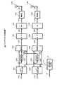
このように、ARQとパンクチャ処理とを用いた従来の送信装置の構成例を、図1に示す。送信装置20は、送信ディジタル信号1をCRC(Cyclic Redundancy Check)エンコーダ2に入力する。CRCエンコーダ2は、CRCエンコード後の送信ディジタル信号3を畳み込み符号用エンコーダ4に送出する。畳み込み符号用エンコーダ4は、CRCエンコード後の送信ディジタル信号3に畳み込み符号化処理を施し、畳み込み符号化後の送信ディジタル信号5をパンクチャ部6に送出する。 A configuration example of a conventional transmission apparatus using ARQ and puncture processing is shown in FIG. The transmission device 20 inputs the transmission
パンクチャ部6は、畳み込み符号化後の送信ディジタル信号5をパンクチャリングし、パンクチャリング後の送信ディジタル信号7を選択部12に送出すると共に、符号化の際に発生した冗長な情報8を記憶部9に送出する。ここで、例えば畳み込み符号用エンコーダ4が、符号化率1/2で符号化を行ったとすると、パンクチャ部6はパンクチャリングによって、例えば符号化率3/4のパンクチャリング後の送信ディジタル信号7を形成する。 The
記憶部9に記憶された冗長情報8は、通信相手からACK/NACK信号11としてACK(acknowledgement)信号が送られてきたときには破棄され、NACK(negative-acknowledgement)信号が送られてきたときには、再送信号として選択部12に送出される。 The
選択部12は、ACK信号を入力したときには、パンクチャリング後の送信ディジタル信号7を選択出力する一方、NACK信号を入力したときには、記憶部9に記憶されている冗長情報10を選択出力する。つまり、選択部12は、再送要求があった場合のみ、冗長情報10を再送信号として選択するようになっている。 When the ACK signal is input, the
変調部14は、選択部12によって選択された送信ディジタル信号13に対して、QPSKや16QAMなどの変調を施し、これにより得た変調信号15を、無線部(RF部)16に送出する。RF部16は、変調信号15に周波数変換等の所定の無線処理を施し、これにより得た送信信号17をアンテナ18に送出する。
ところで、シャノン限界に近い性能を持ち、ブロック誤り率特性が良く、エラーフロアがほとんど発生しない、といった優れた復号特性を得ることができる符号化方式として、LDPC(Low Density Parity Check)符号化が注目されている。 By the way, LDPC (Low Density Parity Check) coding is a focus of attention as an encoding method that can achieve excellent decoding characteristics such as performance close to the Shannon limit, good block error rate characteristics, and almost no error floor. Has been.
ところが、ターボ符号等の畳み込み符号に換えて、LDPC符号を用いてARQを行おうとすると、以下のような問題が生じる。すなわち、LDPC符号とパンクチャ処理とを組み合わせて、ARQを実現しようとした場合、適切なパンクチャ処理を施すことができるようなLDPC符号は、非常に限られてしまう。このため、設計の自由度が小さくなる問題がある。またパンクチャ処理を行わずに、前回送信した全データを再送すると、再送データ量が増えてしまうので現実的でない。 However, if ARQ is performed using an LDPC code instead of a convolutional code such as a turbo code, the following problems occur. That is, when an ARQ is realized by combining an LDPC code and a puncture process, LDPC codes that can perform an appropriate puncture process are very limited. For this reason, there is a problem that the degree of freedom in design is reduced. Also, if all the previously transmitted data is retransmitted without performing puncturing, the amount of retransmitted data increases, which is not realistic.
従って、パンクチャ処理を必要としない新しいARQを実現する必要がある。このとき、再送回数が少なくて済み、かつその方法も簡単であることが望まれる。 Therefore, it is necessary to realize a new ARQ that does not require puncturing. At this time, it is desired that the number of retransmissions is small and the method is simple.
本発明はかかる点に鑑みてなされたものであり、LDPC符号を用いたマルチアンテナ通信システムにおいて、簡易な方法で、適用可能なLDPC符号が限定されず、かつ少ない再送データで効果的に再送により受信品質を向上させることができるマルチアンテナ送信装置、マルチアンテナ受信装置及びデータ再送方法を提供することを目的とする。 The present invention has been made in view of such points, and in a multi-antenna communication system using an LDPC code, applicable LDPC codes are not limited by a simple method, and can be effectively retransmitted with a small amount of retransmission data. An object of the present invention is to provide a multi-antenna transmission apparatus, a multi-antenna reception apparatus, and a data retransmission method capable of improving reception quality.
かかる課題を解決するため本発明は、送信データを、LDPC符号を用いて符号化するLDPC符号化手段と、LDPC符号化された送信データを複数のアンテナに割り当てて送信する送信手段と、再送する場合には、前回送信したLDPC符号化データのうちの一部のLDPC符号化データのみを再送するように送信制御する送信制御手段とを具備し、前記再送する一部のLDPC符号化データは、検査行列Hのn個の列ベクトルのうち、1の数をより多く含む上位K(1<K<n)個の列ベクトルを用いて得たKビットのデータである構成を採る。In order to solve such a problem, the present invention retransmits transmission data by using LDPC encoding means for encoding transmission data, transmission means for assigning and transmitting LDPC encoded transmission data to a plurality of antennas, and retransmitting the transmission data. In this case, it comprises transmission control means for controlling transmission so as toretransmit only a part of the LDPC encoded data transmitted last time, and the part of the LDPC encoded data to beretransmittedis: The configurationis K-bit data obtained by using upper K (1 <K <n) column vectors including a larger number of 1 out of n column vectors of parity check matrix H.
この構成によれば、再送時には、前回送信したLDPC符号化データのうちの一部の符号化データのみを再送し、前記再送する一部のLDPC符号化データは、検査行列Hのn個の列ベクトルのうち、1の数をより多く含む上位K(1<K<n)個の列ベクトルを用いて得たKビットのデータであるようにしたので、再送された一部のLDPC符号が品質の良い状態で受信されるようになる。ここで、LDPC符号は、畳み込み符号等と比較して、拘束長が非常に長いため、一部のデータの品質が良いと、復号時に品質の良い一部のデータに引きずられて、他の復号データの誤り率が改善する特性があるので、全体的な復号データの誤り率特性が向上する。この結果、再送するにあたって、畳み込み符号等と比較して少ない再送データで、かつパンクチャを行わないのでLDPC符号の自由度を低下させることなく、再送により受信データの誤り率特性を劇的に改善することができるようになる。加えて、前記再送する一部のLDPC符号化データは、検査行列Hのn個の列ベクトルのうち、1の数をより多く含む上位K(1<K<n)個の列ベクトルを用いて得たKビットのデータであるようにしたので、誤り耐性の強いデータを再送データとして用いることができるので、再送による受信品質の向上効果を一段と望める。According to this configuration, at the time of retransmission, only a part of the previously transmitted LDPC encoded data isretransmitted, and the retransmitted part of the LDPC encoded data includes n columns of the check matrix H. Among the vectors, K bits data obtained by using upper K (1 <K <n) column vectors including a larger number of 1 are used , so that some of the retransmitted LDPC codes have quality Will be received in good condition. Here, since the LDPC code has a very long constraint length compared to a convolutional code or the like, if the quality of some data is good, it is dragged to some data with good quality at the time of decoding, and other decoding Since there is a characteristic that the error rate of the data is improved, the error rate characteristic of the overall decoded data is improved. As a result, when retransmitting, the amount of retransmitted data is small compared to a convolutional code and the like, and puncturing is not performed, so that the error rate characteristics of received data are dramatically improved by retransmission without reducing the degree of freedom of the LDPC code. Will be able to.In addition, a part of LDPC encoded data to be retransmitted uses upper K (1 <K <n) column vectors including a larger number of 1 among n column vectors of the parity check matrix H. Since the obtained K-bit data is used, data with high error tolerance can be used as retransmission data, so that the effect of improving reception quality by retransmission can be further expected.
このように本発明によれば、LDPC符号を用いたマルチアンテナ通信システムにおいて、簡易な方法で、適用可能なLDPC符号が限定されず、かつ少ない再送データで効果的に再送により受信品質が向上させることができるマルチアンテナ送信装置、マルチアンテナ受信装置及びデータ再送方法を実現できる。 As described above, according to the present invention, in a multi-antenna communication system using LDPC codes, applicable LDPC codes are not limited by a simple method, and reception quality is improved by retransmission effectively with a small amount of retransmission data. A multi-antenna transmission apparatus, a multi-antenna reception apparatus, and a data retransmission method can be realized.
本発明の発明者らは、LDPC符号は、ターボ符号等の畳み込み符号と比較して拘束長が長く、一部のデータの受信品質が良ければ、他のデータの誤り率特性も受信品質が良い一部のデータに伴って向上するといった特性を持っていることに着目した。そして本発明の発明者らは、LDPC符号を再送するにあたって、一部のデータのみを十分な品質で再送すれば、パンクチャを行わなくても、少ない再送データで再送による十分な誤り率特性の向上効果が得られると考えた。 The inventors of the present invention show that the LDPC code has a longer constraint length than a convolutional code such as a turbo code, and if the reception quality of some data is good, the error rate characteristics of other data are also good. We paid attention to the characteristics of improving with some data. The inventors of the present invention, when retransmitting an LDPC code, retransmit only a part of data with sufficient quality, and can improve error rate characteristics sufficiently by retransmitting with a small amount of retransmitted data without performing puncturing. I thought it would be effective.
本発明の特徴は、再送時に、前回送信したLDPC符号化データのうちの一部のLDPC符号化データのみを、前回送信時よりもダイバーシチゲインの高い送信方法を用いて送信するようにしたことである。これにより、パンクチャを行わなくても、少ない再送データで効果的に再送により受信品質を向上させることができる。 A feature of the present invention is that, at the time of retransmission, only a part of the LDPC encoded data transmitted last time is transmitted using a transmission method having a diversity gain higher than that at the previous transmission. is there. As a result, the reception quality can be improved by retransmission effectively with a small amount of retransmission data without performing puncturing.
(実施の形態)
以下、本発明の実施の形態について図面を参照して詳細に説明する。(Embodiment)
Hereinafter, embodiments of the present invention will be described in detail with reference to the drawings.
図2に、本発明の実施の形態に係るマルチアンテナ送信装置の構成を示す。マルチアンテナ送信装置100は、例えば無線基地局に設けられる。マルチアンテナ送信装置100は、所謂OFDM−MIMO通信を行う送信装置であり、2つのアンテナから、それぞれ異なる変調信号を送信するようになっている。具体的には、アンテナ114Aからは、変調信号Aを送信すると共に、アンテナ114Bからは、変調信号Bを送信する。ここで図2では、変調信号Aについての信号処理系統と、変調信号Bについての信号処理系とは、ほぼ同様の構成であるため、変調信号Aの処理系統については、符号の後ろに「A」を付けて示し、変調信号Aについての信号処理系統と対応する変調信号Bの処理系統については、符号の後ろに「B」を付けて示した。 FIG. 2 shows the configuration of the multi-antenna transmission apparatus according to the embodiment of the present invention. The
マルチアンテナ送信装置100のフレーム構成信号生成部116は、送信制御手段として機能するものであり、通信相手(ここでは通信相手を「端末」と名付ける)から送信された再送要求情報であるACK/NACK信号115に基づいて、送信フレーム構成を決定し、決定した送信フレーム構成をフレーム構成信号117として、LDPC符号化部102A、102B及び変調部106A、106Bに送出する。 Frame configuration
LDPC符号化部102A、102Bは、変調信号Aの送信ディジタル信号101A、101Bとフレーム構成信号117とを入力し、送信ディジタル信号101A、101Bを、CRC(Cyclic Redundancy Check)符号化及びLDPC符号化し、符号化された変調信号A、Bの送信ディジタル信号103A、103Bを、変調部106A、106Bに送出する。また符号化された変調信号A、Bの送信ディジタル信号103A、103Bは、それぞれ記憶部104A、104Bに記憶される。記憶部104A、104Bに記憶されたデータは再送に用いられる。
各変調部106A、106Bは、QPSK(QuadraturePhase Shift Keying)や16QAM等の変調処理を行う。変調部106Aは、フレーム構成信号117に基づいて、送信ディジタル信号103A、105A、105Bのいずれかを変調する。具体的には、再送でない場合には、符号化された変調信号Aの送信ディジタル信号103Aを変調して出力し、変調信号Aを再送する要求があった場合には、記憶部104Aに記憶されている符号化された変調信号Aの送信ディジタル信号105Aを変調して出力し、変調信号Bを再送する要求があった場合には、記憶部104Bに記憶されている符号化された変調信号Bの送信ディジタル信号105Bを変調して出力する。 Each of the
一方、変調部106Bは、フレーム構成信号117に基づいて、送信ディジタル信号103Bを変調する。具体的には、再送でない場合には、符号化された変調信号Bの送信ディジタル信号103Bを変調して出力し、再送時には何も出力しない。 On the other hand,
これにより、通常の送信時には、2つのアンテナ114A、114Bから異なる変調信号A、Bが送信されるのに対して、再送時には、1つのアンテナ114Aのみから再送要求された変調信号が送信される。この結果、再送時には、1つのアンテナ114Aのみから送信された変調信号が、受信側の複数アンテナで受信されるようになるので、ダイバーシチゲインの高い送信を行うことができるようになる。よって、通常送信時よりも再送時の受信品質を高めることができる。 Thereby, different modulation signals A and B are transmitted from the two
各変調部106A、106Bから出力された変調信号107A、107Bは、それぞれシリアルパラレル変換部(S/P)108A、108Bによって、パラレル信号109A、109Bとされ、続く逆フーリエ変換部(idft)110A、110Bによって、逆フーリエ変換されることにより、OFDM信号111A、111Bとされる。各OFDM信号111A、111Bは、無線部112A、112Bによって、周波数変換等の所定の無線処理が施されて送信信号113A、113Bとされた後、アンテナ114A、114Bから送信される。因みに、本実施の形態では、基本的には、アンテナ114Aから送信する信号を変調信号Aと呼び、アンテナ114Bから送信する信号を変調信号Bと呼ぶものとする。 The modulation signals 107A and 107B output from the
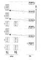
図3に、マルチアンテナ送信装置100が、通常送信(すなわち再送でない送信)を行う場合の、各アンテナ114A、114Bから送信する変調信号のフレーム構成例を示す。図3に示すように、マルチアンテナ送信装置100は、変調信号Aと変調信号Bとを異なるアンテナから同時に送信する。図3において、制御情報シンボル201は、フレーム構成、再送データであるか否かの情報、再送回数などの制御情報を伝送するためのシンボルである。パイロットシンボル202、受信側で伝送路の状態を推定するためのシンボルである。データシンボル203は、CRC符号化及びLDPC符号化されたデータである。図3Aに示すフレーム構成の変調信号Aの信号が、アンテナ114Aから送信され、図3Bに示すフレーム構成の変調信号Bの信号が、アンテナ114Bから送信される。また、同一キャリア、同一時刻のシンボルは、同時に送信されるものとする。 FIG. 3 shows an example of a frame configuration of a modulated signal transmitted from each of the
図4に、本実施の形態のマルチアンテナ受信装置の構成を示す。マルチアンテナ受信装置300は、マルチアンテナ送信装置100が搭載された基地局と通信を行う端末とに搭載されている。 FIG. 4 shows the configuration of the multi-antenna reception apparatus of this embodiment.
また図5に、本実施の形態のマルチアンテナ通信システムの全体構成を示す。先ず、図4のマルチアンテナ受信装置300の構成を説明する前に、図5のマルチアンテナ通信システム400の全体的な動作について説明する。 FIG. 5 shows the overall configuration of the multi-antenna communication system of the present embodiment. First, before describing the configuration of the
マルチアンテナ通信システシステム400は、図2のマルチアンテナ送信装置100と、図4のマルチアンテナ受信装置300とを有する。マルチアンテナ送信装置100は、送信部401(図2のアンテナ114A、114Bを除いた部分に相当)において、送信ディジタル信号101A、101Bから変調信号A(113A)、変調信号B(113B)を形成し、変調信号A(113A)と変調信号B(113B)とを各アンテナ114A、114Bから送信する。なお図5では、変調信号A(113A)をTxa(t)と示し、変調信号B(113B)をTxb(t)と示した。 The multi-antenna communication system system 400 includes the
マルチアンテナ受信装置300は、各アンテナ301X、301Yで受信した受信信号302X、302Y(図5ではR1(t)、R2(t)と示した)を、受信部402(図4のアンテナ301X、301Yを除いた部分に相当)に入力する。受信部402は、受信信号R1(t)、R2(t)に対して復調処理を施すことにより、送信ディジタル信号101A、101Bに対応する受信データ316A、316Bを得る。また受信部402は、送信ディジタル信号101A、101Bに対応するACK/NACK信号317A、317Bを得る。 The
ここで、アンテナ114Aから送信された変調信号Txa(t)は、チャネル変動h11(t)、h12(t)を受けた後にアンテナ301X、301Yで受信される。またアンテナ114Bから送信された変調信号Txb(t)は、チャネル変動h21(t)、h22(t)を受けた後にアンテナ301X、301Yで受信される。 Here, modulated signal Txa (t) transmitted from
よって、以下の関係式が成立する。
次に、図4に示した本実施の形態のマルチアンテナ受信装置300の構成を説明する。マルチアンテナ受信装置300は、アンテナ301X、301Yで受信した受信信号302X、302Yを無線部303X、303Yに入力する。無線部303X、303Yは、それぞれ受信信号302X、302Yに対して、周波数変換等の所定の無線処理を施すことにより、受信ベースバンド信号304X、304Yを得て、受信ベースバンド信号304X、304Yをフーリエ変換部(dft)305X、305Yに送出する。 Next, the configuration of
フーリエ変換部305X、305Yは、それぞれ受信ベースバンド信号304X、304Yに対してフーリエ変換処理を施し、フーリエ変換後の信号306X、306Yを出力する。 The
変調信号Aのチャネル変動推定部307Xは、フーリエ変換後の信号306Xを入力とし、図3の変調信号Aのパイロットシンボル202を検出し、変調信号Aのパイロットシンボル202に基づいて変調信号Aのチャネル変動を推定、つまり(1)式のh11(t)を推定する。このとき、変調信号Aのチャネル変動推定部307Xは、キャリア毎に変調信号Aのチャネル変動を推定する。そして変調信号Aのチャネル変動推定部307Xは、変調信号Aのキャリア毎のチャネル推定信号308Xを出力する。 Modulated signal A channel
変調信号Bのチャネル変動推定部309Xは、フーリエ変換後の信号306Xを入力とし、図3の変調信号Bのパイロットシンボル202を検出し、変調信号Bのパイロットシンボル202に基づいて変調信号Bのチャネル変動を推定、つまり(1)式のh12(t)を推定する。このとき、変調信号Bのチャネル変動推定部309Xは、キャリア毎に変調信号Bのチャネル変動を推定する。そして変調信号Bのチャネル変動推定部309Xは、変調信号Bのキャリア毎のチャネル推定信号310Xを出力する。 Modulated signal B channel
変調信号Aのチャネル変動推定部307Yは、フーリエ変換後の信号306Yを入力とし、図3の変調信号Aのパイロットシンボル202を検出し、これに基づいて変調信号Aのチャネル変動を推定、つまり(1)式のh21(t)を推定する。このとき、変調信号Aのチャネル変動推定部307Yは、キャリア毎に変調信号Aのチャネル変動を推定する。そして変調信号Aのチャネル変動推定部307Yは、変調信号Aのキャリア毎のチャネル推定信号308Yを出力する。 The channel
変調信号Bのチャネル変動推定部309Yは、フーリエ変換後の信号306Yを入力とし、図3の変調信号Bのパイロットシンボル202を検出し、変調信号Bのパイロットシンボル202に基づいて変調信号Bのチャネル変動を推定、つまり(1)式のh22(t)を推定する。このとき、変調信号Bのチャネル変動推定部309Yは、キャリア毎に変調信号Bのチャネル変動を推定する。そして変調信号Bのチャネル変動推定部309Yは、変調信号Bのキャリア毎のチャネル推定信号310Yを出力する。 Modulated signal B channel fluctuation estimation section 309Y receives
制御情報検波部318は、フーリエ変換後の信号306X、306Yを入力とし、図3の制御情報シンボル201を検出し、制御情報シンボル201に基づいてフレーム構成についての情報、再送データであるか否かの情報や、再送回数情報などからなる制御情報319を得て、制御情報319を信号処理部311及び復号部313A、313Bに出力する。 The control
信号処理部311は、変調信号Aのチャネル推定信号308X、308Y、変調信号Bのチャネル推定信号310X、310Y、フーリエ変換後の信号306X、306Y、制御情報319を入力とし、制御情報319が示しているフレーム構成、再送データであるか否かの情報に基づいて、再送データでない場合、例えば(1)式の逆行列演算を施すことで各変調信号A、Bを分離し、変調信号Aのベースバンド信号をベースバンド信号312Aとして、変調信号Bのベースバンド信号をベースバンド信号312Bとして出力する。これに対して、再送データの場合、信号処理部311は、最大比合成、時空間ブロック符号のための信号処理、又はCyclic Delay Diversityのための信号処理を施し、ベースバンド信号312A及び又はベースバンド信号312Bを出力する。 The
復号部313Aは、ベースバンド信号312A、制御情報319を入力とし、制御情報319における再送データであるか否かの情報に基づき、変調信号Aの復号を行い、変調信号Aの復号後のディジタル信号314Aを出力する。このとき、復号部313Aは、制御情報319によって再送でないことが示された場合には、通常のLDPC復号処理を行う。これに対して、復号部313Aは、制御情報319によって再送であることが示された場合には、前回受信したLDPC符号化データ(すなわち記憶しておいたLDPC符号化データ)のうち、再送された一部のLDPC符号化データに対応するLDPC符号化データを、再送されたLDPC符号化データに置き換えて、LDPC復号処理を行うようになっている。 Decoding
CRCチェック部315Aは、変調信号Aの復号後のディジタル信号314Aを入力とし、CRCチェックを行い、誤りの発生状況を検出する。次に、誤りが発生していない場合、変調信号Aの受信データ316Aを出力するとともに、通信相手に送信するACK/NACK信号317AとしてACK信号を形成する。これに対して、CRCチェック部315Aは、誤りが発生した場合、受信データを出力せずに、通信相手に送信するACK/NACK信号317AとしてNACK信号を形成する。
同様に、復号部313Bは、ベースバンド信号312B、制御情報319を入力とし、制御情報319における再送データであるか否かの情報に基づき、変調信号Bの復号を行い、変調信号Bの復号後のディジタル信号314Bを出力する。このとき、復号部313Bは、制御情報319によって再送でないことが示された場合には、通常のLDPC復号処理を行う。これに対して、復号部313Bは、制御情報319によって再送であることが示された場合には、前回受信したLDPC符号化データ(すなわち記憶しておいたLDPC符号化データ)のうち、再送された一部のLDPC符号化データに対応するLDPC符号化データを、再送されたLDPC符号化データに置き換えて、LDPC復号処理を行うようになっている。 Similarly, decoding
CRCチェック部315Bは、変調信号Bの復号後のディジタル信号314Bを入力とし、CRCチェックを行い、誤りの発生状況を検出し、誤りが発生していない場合、変調信号Bの受信データ316Bを出力するとともに、通信相手に送信するACK/NACK信号317BとしてACK信号を形成する。これに対して、CRCチェック部315Bは、誤りが発生した場合、受信データを出力せずに、通信相手に送信するACK/NACK信号317BとしてNACK信号を形成する。
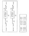
図6に、復号部313A(313B)の構成例を示す。復号部313Aと復号部313Bとは同様の構成なので、ここでは復号部313Aの構成についてのみ説明する。 FIG. 6 shows a configuration example of the
復号部313Aは、LDPC復号部501と記憶部502とを有する。記憶部502には、前回までに受信したベースバンド信号312Aが記憶される。LDPC復号部501は、制御情報319により再送でないことが示されている場合には、今回受信したベースバンド信号312Aのみを用いてLDPC復号処理を行うことで、復号後のディジタル信号314Aを得る。これに対して、LDPC復号部501は、制御情報319により再送であることが示されている場合には、記憶部502に記憶されている前回までのベースバンド信号503と今回再送されたベースバンド信号312Aとを用いて、LDPC復号処理を行う。このときLDPC復号部501は、記憶部502に記憶されている前回までに受信したベースバンド信号503のうち、再送されたベースバンド信号312A(再送された一部のLDPC符号化データ)に対応する信号を、再送されたベースバンド信号312Aに置き換えて、LDPC復号処理を行うようになっている。 The
次に、本実施の形態の動作について説明する。先ず、マルチアンテナ送信装置100(以下これを基地局と呼ぶ)と、マルチアンテナ受信装置300(以下これを端末と呼ぶ)との全体的な送受信の流れの一例を、図7に示す。 Next, the operation of the present embodiment will be described. First, FIG. 7 shows an example of the overall transmission / reception flow between the multi-antenna transmission apparatus 100 (hereinafter referred to as a base station) and the multi-antenna reception apparatus 300 (hereinafter referred to as a terminal).
はじめに、基地局は、図7<1>のように、変調信号Aによりデータ1A、変調信号Bによりデータ1Bを送信する。 First, the base station transmits data 1A by modulated signal A and data 1B by modulated signal B as shown in <1> of FIG.
端末は、この信号を受信し、誤りが発生していないと、図7<2>のように基地局に対し、再送要求を行わない。すると、基地局は、図7<3>のように変調信号Aにより新たなデータ2A、変調信号Bにより新たなデータ2Bを送信する。 If the terminal receives this signal and no error has occurred, the terminal does not make a retransmission request to the base station as shown in FIG. 7 <2>. Then, the base station transmits new data 2A by the modulation signal A and new data 2B by the modulation signal B as shown in <3> of FIG.
端末は、この信号を受信し、誤りが発生していると、図7<4>のように基地局に対し、再送要求を行う。すると、基地局は、図7<5>のように、前回送信したデータ2Aのうちの一部のデータ(以下このようなデータを部分データと呼ぶ)2A,P1と、前回送信したデータ2Bのうちの部分データ2B,P1のみを再送する。 When the terminal receives this signal and an error occurs, the terminal makes a retransmission request to the base station as shown in <4> of FIG. Then, as shown in FIG. 7 <5>, the base station sets a part of the data 2A transmitted last time (hereinafter, such data is referred to as partial data) 2A, P1, and the data 2B transmitted last time. Only the partial data 2B and P1 are retransmitted.
端末は、基地局が図7<3>で送信したデータ2A、データ2Bの受信信号と、図7<5>で送信した変調信号Aの部分データ2A,P1、変調信号Bの部分データ2B,P1の受信信号を用いてLDPC復号を行う。その結果、誤りが発生しないと、図7<6>のように基地局に対し、再送要求を行わない。すると、基地局は、図7<7>のように変調信号Aにより新たなデータ3A、変調信号Bにより新たなデータ3Bを送信する。 The terminal receives the data 2A and data 2B received signals transmitted by the base station in FIG. 7 <3>, the partial data 2A and P1 of the modulated signal A transmitted in FIG. 7 <5>, and the partial data 2B of the modulated signal B. LDPC decoding is performed using the received signal of P1. As a result, if no error occurs, no retransmission request is made to the base station as shown in <6> of FIG. Then, the base station transmits new data 3A using the modulation signal A and new data 3B using the modulation signal B as shown in FIG.
端末は、この信号を受信し、誤りが発生していると、図7<8>のように基地局に対し、再送要求を行う。すると、基地局は、図7<9>のように、前回送信したデータ3Aの部分データ3A,P1と、前回送信したデータ3Bの部分データ3B,P1のみを再送する。 When the terminal receives this signal and an error occurs, the terminal makes a retransmission request to the base station as shown in FIG. 7 <8>. Then, as shown in FIG. 7 <9>, the base station retransmits only the partial data 3A and P1 of the previously transmitted data 3A and the partial data 3B and P1 of the previously transmitted data 3B.
端末は、基地局が図7<7>で送信したデータ3A、データ3Bの受信信号と、図7<9>で送信した変調信号Aの部分データ3A,P1、変調信号Bの部分データ3B,P1の受信信号を用いてLDPC復号を行う。その結果、未だ誤りが発生していると、図7<10>のように基地局に対し、再び、再送要求を行う。 The terminal receives the reception signals of the data 3A and data 3B transmitted by the base station in FIG. 7 <7>, the partial data 3A and P1 of the modulation signal A transmitted in FIG. 7 <9>, the partial data 3B of the modulation signal B, LDPC decoding is performed using the received signal of P1. As a result, if an error still occurs, a retransmission request is made again to the base station as shown in <10> of FIG.
すると、基地局は、図7<11>のように、データ3Aの部分データ3A,P2と、データ3Bの部分データ3B,P2のみを再送する。この2回目の再送で送信する部分データ3A,P2は、1回目の再送で部分データ3A,P1とは異なるデータである。同様に、2回目の再送で送信する部分データ3B,P2は、1回目の再送で送信した部分データ3B,P1とは異なるデータである。 Then, the base station retransmits only the partial data 3A and P2 of the data 3A and the partial data 3B and P2 of the data 3B as shown in FIG. 7 <11>. The partial data 3A and P2 transmitted by the second retransmission are data different from the partial data 3A and P1 by the first retransmission. Similarly, the partial data 3B and P2 transmitted by the second retransmission are different from the partial data 3B and P1 transmitted by the first retransmission.
端末は、基地局が図7<7>で送信したデータ3A、データ3Bの受信信号、図7<9>で送信した部分データ3A,P1、部分データ3B,P1の受信信号、図7<11>で送信した部分データ3A,P2、部分データ3B,P2の受信信号を用いてLDPC復号を行う。その結果、誤りが発生しないと、図7<12>のように基地局に対し、再送要求を行わない。 The terminal receives the data 3A and data 3B reception signals transmitted by the base station in FIG. 7 <7>, the partial data 3A and P1 and partial data 3B and P1 reception signals transmitted in FIG. 7 <9>, and FIG. The LDPC decoding is performed using the reception signals of the partial data 3A and P2 and the partial data 3B and P2 transmitted in the above. As a result, if no error occurs, a retransmission request is not sent to the base station as shown in <12> of FIG.
次に、LDPC符号化部102A、102Bの動作について、図8を用いて詳しく説明する。ただし、ここでは説明を簡単化するために、CRC符号化については省略する。またここでは、特に、図7に示すように、最初に送信するデータ3A、1回目に再送する部分データ3A,P1、及び、2回目に再送する部分データ3A,P2の場合と、最初に送信するデータ3B、1回目に再送する部分データ3B,P1、及び、2回目に再送する部分データ3B,P2の場合と、を例にとって説明する。 Next, the operation of the
変調信号A用のLDPC符号化部102Aは、符号化前の送信ディジタル信号101AをLDPC符号化することにより、LDPC符号化データ103Aを出力する。例えば、送信ディジタル信号101Aを(m1a,m2a,・・・,m1603a)とし、パリティチェックマトリクスをGとすると、LDPC符号化データ103Aとして(C1a,C2a,・・・,C2000a)を出力する。 The
変調信号B用のLDPC符号化部102Bは、符号化前の送信ディジタル信号101BをLDPC符号化することにより、LDPC符号化データ103Bを出力する。例えば、送信ディジタル信号101Bを(m1b,m2b,・・・,m1603b)とし、パリティチェックマトリクスをGとすると、LDPC符号化データ103Bとして(C1b,C2b,・・・,C2000b)を出力する。 The
初回送信時には、このようにして生成されたLDPC符号化データ(C1a,C2a,・・・,C2000a)、(C1b,C2b,・・・,C2000b)が、データ3A、3Bとして、異なるアンテナ114A、114Bから送信される。またこれらのLDPC符号化データ(C1a,C2a,・・・,C2000a)のうち一部又は全部が記憶部104Aに記憶され、LDPC符号化データ(C1b,C2b,・・・,C2000b)の一部又は全部が記憶部104Bに記憶される。 At the time of initial transmission, the LDPC encoded data (C1a, C2a,..., C2000a) and (C1b, C2b,..., C2000b) generated in this way are
そして、一回目の再送時には、図8Bに示すように、記憶部104Aに記憶されている一部のLDPC符号化データ(C101a,C102a,・・・,C600a)が、部分データ3A,P1として送信されると共に、記憶部104Bに記憶されている一部のLDPC符号化データ(C101b,C102b,・・・,C600b)が、部分データ3B,P1として送信される。ここで本実施の形態では、これらの部分データを再送するにあたっては、1つのアンテナ114Aのみから送信するようになっている。 Then, at the first retransmission, as shown in FIG. 8B, a part of LDPC encoded data (C101a, C102a,..., C600a) stored in the
2回目の再送時には、図8Bに示すように、記憶部104Aに記憶されているLDPC符号化データのうち、1回目に再送したのとは異なるLDPC符号化データ(C901a,C902a,・・・,C1400a)が、部分データ3A,P2として送信されると共に、記憶部104Bに記憶されているLDPC符号化データのうち、1回目に再送したのとは異なるLDPC符号化データ(C901b,C902b,・・・,C1400b)が、部分データ3B,P2として送信される。これらの部分データを再送するにあたっても、1つのアンテナ114Aのみから送信するようになっている。 At the time of the second retransmission, as shown in FIG. 8B, among the LDPC encoded data stored in the
このような再送が行われた場合について、図6に示す復号部313Aの処理を説明する。先ず、初回送信でデータ3A、3Bが送信されると(図7<7>)、LDPC復号部501でデータ3A、3BをLDPC復号すると共に、記憶部502にデータ3A、3Bを記憶する。1回目の再送時(図7<9>)、LDPC復号部501は再送された部分データ3A,P1、部分データ3B,P1と、記憶部502に記憶されているデータ3A、3Bとを用いてLDPC復号処理を行うと共に、再送された部分データ3A,P1、部分データ3B,P1を記憶部502に記憶する。2回目の再送時(図7<11>)、LDPC復号部501は再送された部分データ3A,P2、部分データ3B,P2と、記憶部502に記憶されているデータ3A、3B、3A,P1、3B,P1とを用いてLDPC復号処理を行う。 A process performed by the
次に、本実施の形態のように、再送時には1本のアンテナ114Aのみから再送信号を送信することにより、通常送信時よりもダイバーシチゲインが得られ、再送データ(部分データ)の受信品質を向上させることができる理由について説明する。 Next, as in this embodiment, by transmitting a retransmission signal from only one
図5との対応部分に同一符号を付して示す図9に、再送データを送信するときのイメージを示す。マルチアンテナ送信装置100は、変調信号をアンテナ114Aのみから送信する。すると、アンテナ114Aから送信される変調信号は、伝搬路上でh11(t)、h12(t)の伝搬係数が乗算され、受信アンテナ301X、301Yで受信される。したがって、マルチアンテナ受信装置300の受信部402では、アンテナ114から送信された変調信号を最大比合成できるので、再送されたデータの受信品質が向上することになる。 FIG. 9 in which the same reference numerals are assigned to the parts corresponding to those in FIG. 5 shows an image when retransmission data is transmitted.
因みに、図7<7>において、異なるアンテナから送信されたデータ3A、データ3Bは受信品質が悪いため、端末において図7<8>のように再送が要求される。このとき、伝搬環境に大きな変化がないような環境下では、再送データも図7<7>と同様にMIMO多重を行って送信すると、受信品質の改善効果が全くないわけではないが、大きな改善効果につながらない可能性がある。 Incidentally, in FIG. 7 <7>, since the data 3A and data 3B transmitted from different antennas have poor reception quality, the terminal is required to retransmit as shown in FIG. 7 <8>. At this time, in an environment where there is no significant change in the propagation environment, if retransmission data is transmitted by performing MIMO multiplexing in the same way as in FIG. 7 <7>, the reception quality improvement effect is not completely eliminated, but a great improvement is achieved. It may not lead to an effect.
これに対して、本実施の形態においては、再送時には、前回送信時よりも少ないアンテナからLDPC符号化データの部分データを送信するようにしたことにより、受信側で大きなダイバーシチゲインが得られるので、伝搬環境に大きな変化がないような環境下でも、再送した部分データの受信品質を向上させることができ、再送によって大きな受信品質の改善効果を得ることができる。 On the other hand, in this embodiment, at the time of retransmission, by transmitting partial data of LDPC encoded data from fewer antennas than at the time of previous transmission, a large diversity gain can be obtained on the receiving side. Even in an environment in which there is no significant change in the propagation environment, the reception quality of the retransmitted partial data can be improved, and a large reception quality improvement effect can be obtained by the retransmission.
加えて、再送時に、変調方式の多値数を減少させるようにすれば、再送された部分データの受信品質を一段と向上させることができるので、再送によって一段と大きな受信品質の改善効果を得ることができる。 In addition, if the multi-value number of the modulation scheme is reduced at the time of retransmission, the reception quality of the retransmitted partial data can be further improved, so that it is possible to obtain a much larger reception quality improvement effect by retransmission. it can.
ここで、本実施の形態の送信方法が従来のARQと異なる点は、本実施の形態で再送するデータ3A,P1、データ3A,P2、データ3B,P1、データ3B,P2は、パンクチャすることによって得たデータではなく、単なる部分データ(前回送信したデータの一部)であるということである。これにより、本実施の形態においては、パンクチャ処理を行わないので、どのようなLDPC符号に対しても適用することができる。すなわち、パンクチャ処理に伴うLDPC符号の限定を受けない。 Here, the transmission method of this embodiment is different from the conventional ARQ in that data 3A, P1, data 3A, P2, data 3B, P1, and data 3B, P2 to be retransmitted in this embodiment are punctured. This means that it is not the data obtained by (1) but merely partial data (part of the data transmitted last time). Thus, in the present embodiment, since puncturing is not performed, the present invention can be applied to any LDPC code. That is, the LDPC code is not limited by the puncturing process.
またパンクチャを用いた従来のARQでは、再送するデータは、パンクチャリングの際に発生した(つまり符号化の際に発生した)冗長な情報に限られるが、本実施の形態における再送方法では、これに限定されることがないので、非常に柔軟性のある再送を行うこともできる。例えば、ACK/NACK信号と同時に受信品質に相当する情報を通信相手から受け取り、再送する部分データの量を変更するといった処理も行うことができ、通信状況に応じて再送データの量を変更するといった適応的な再送方法を行うこともできるようになる。 In the conventional ARQ using puncturing, the data to be retransmitted is limited to redundant information generated at the time of puncturing (that is, generated at the time of encoding). Therefore, very flexible retransmission can be performed. For example, information corresponding to the reception quality can be received from the communication partner at the same time as the ACK / NACK signal, and the amount of partial data to be retransmitted can be changed, and the amount of retransmission data can be changed according to the communication status. An adaptive retransmission method can also be performed.
ここで、本実施の形態では、パンクチャ処理を行わずに、単なる部分データのみを再送するといった単純な再送処理で、有効に受信データの誤りを削減できる理由について説明する。 Here, in the present embodiment, the reason why errors in received data can be effectively reduced by a simple retransmission process in which only partial data is retransmitted without performing a puncture process will be described.
例えば、畳み込み符号を用いている場合に、パンクチャを行わずに、本実施の形態のように部分データを再送することを考える。畳み込み符号は、LDPC符号と比較して、拘束長が非常に短い。一般に、畳み込み符号では、10程度の拘束長が用いられる。このため、品質の良い部分データを送ったとしても、その影響は拘束長内にとどまってしまう。よって、データブロック全体の誤り率特性を向上させるには、多大な量の部分データを送らなければならなくなってしまう。したがって、本実施の形態で述べたような部分データを再送する方法は、畳み込み符号使用時にはあまり適していないと言える。 For example, when a convolutional code is used, consider retransmitting partial data as in this embodiment without performing puncturing. The convolutional code has a very short constraint length compared to the LDPC code. In general, a constrained code uses a constraint length of about 10. For this reason, even if partial data with good quality is sent, the influence remains within the constraint length. Therefore, in order to improve the error rate characteristics of the entire data block, it is necessary to send a large amount of partial data. Therefore, it can be said that the method of retransmitting the partial data as described in this embodiment is not very suitable when the convolutional code is used.
これに対して、本実施の形態のように、LDPC符号使用時に、パンクチャを行わず、部分データを再送すると、顕著な効果を得ることができる。これは、LDPC符号の拘束長が、畳み込み符号と比較して、非常に長いことに起因する。これを、図8を用いて説明する。例えば、受信側で、送信ディジタル信号m1aは、パリティチェックマトリクスGを用いて生成されたLDPC符号化データ(C1a,C2a,・・・,C2000a)のいくつか情報を用いて推定されることになる。そのいくつかの情報のうちの一部の受信品質が向上すれば、送信ディジタル信号m1aの受信品質(つまり誤り率特性)は向上することになる。これは、送信ディジタル信号m1aに限ったことではなく、送信ディジタル信号m2a〜m1603aについても同様である。つまり、LDPC符号では、拘束長が長いために、一部のデータの誤り率特性を良くすれば、これに伴って拘束長内の他の多くのデータの誤り率特性を良くすることができるようになる。これにより、パンクチャ処理によってLDPC符号が限定されることなしに、かつ少ない再送データ量で、効果的に誤り率特性を改善できるようになる。 On the other hand, a remarkable effect can be obtained by retransmitting partial data without performing puncturing when using an LDPC code as in the present embodiment. This is because the constraint length of the LDPC code is very long compared to the convolutional code. This will be described with reference to FIG. For example, on the receiving side, the transmission digital signal m1a is estimated using some information of LDPC encoded data (C1a, C2a,..., C2000a) generated using the parity check matrix G. . If the reception quality of a part of the some information is improved, the reception quality (that is, the error rate characteristic) of the transmission digital signal m1a is improved. This is not limited to the transmission digital signal m1a, and the same applies to the transmission digital signals m2a to m1603a. In other words, since the LDPC code has a long constraint length, if the error rate characteristics of some data are improved, the error rate characteristics of many other data within the constraint length can be improved accordingly. become. As a result, the error rate characteristic can be effectively improved without limiting the LDPC code by the puncturing process and with a small amount of retransmission data.
次に、再送する一部のデータ(以下これを部分データと呼ぶ)の選び方の好適な例について説明する。 Next, a preferred example of how to select a part of data to be retransmitted (hereinafter referred to as partial data) will be described.
メッセージm=(m1,・・・,mi)、送信系列X=(x1,・・・,xn)T、受信系列Y=(y1,・・・,yn)Tとする。ここで、m<n、Tは転置を表す。生成行列をG、検査行列をHとすると、次式の関係が成立する。
LDPC符号化では、メッセージmと生成行列Gから送信系列Xを生成する。復号側では、受信系列Yと検査行列Hを用いて復号を行う。 In LDPC encoding, a transmission sequence X is generated from a message m and a generation matrix G. On the decoding side, decoding is performed using the reception sequence Y and the check matrix H.
ここで、K個の部分データを再送するものとして、そのK個のデータの選択の仕方について説明する。 Here, a method of selecting the K pieces of data will be described assuming that K pieces of partial data are retransmitted.
検査行列Hのp列のベクトルとq列のベクトルとに着目する。p列のベクトルにおける1の数をPとし、q列のベクトルにおける1の数をQとする。ここではP>Qとする。この場合、送信系列xpと送信系列xqとを比較すると、送信系列xpの方が送信系列xqよりも雑音に対する耐性が強いことになる。これを考慮すると、再送する部分データとしては、検査行列の列ベクトルにおいて、1の数が多い送信系列xpを選択した方が、送信系列xqを選択するよりも好ましい。 Attention is paid to a vector of p columns and a vector of q columns of the check matrix H. Let P be the number of 1's in a vector of p columns and Q be the number of 1's in a vector of q columns. Here, P> Q. In this case, when the transmission sequence xp is compared with the transmission sequence xq, the transmission sequence xp is more resistant to noise than the transmission sequence xq. Considering this, as the partial data to be retransmitted, it is more preferable to select the transmission sequence xp having a larger number of 1 than the transmission sequence xq in the column vector of the check matrix.
本願では、上記の考え方を利用する。具体的には、検査行列Hのj列のベクトル(1<j<n)の1の数が多い上位K個(K<n)の列ベクトルを探索する。ここで、1の数が多い上位K個の列ベクトルの集合を(r1,・・・,rK)とする。そして列ベクトルr1を用いて得られる送信ビットをxr1とし、・・・、列ベクトルrKを用いて得られる送信ビットをxrKとした場合、送信ビット(xr1,・・・,xrK)を再送する部分データとして選択する。つまり、検査行列Hのn個の列ベクトルのうち、1の数をより多く含む上位K(1<K<n)個の列ベクトルを用いて得たKビットのデータを、一部のLDPC符号化データとして再送する。これにより、誤り耐性の強いデータを再送データとして用いることができるので、再送による受信品質の向上効果を一段と望める。In the present application, the above concept is used. Specifically, the top K (K <n) column vectors having a large number of 1 in the j column vector (1 <j <n) of the check matrix H are searched. Here, a set of the top K column vectors having a large number of 1 is defined as (r1,..., RK). And the transmission bit obtained by using the column vectors r1 andx r1, · · ·, if the transmission bit obtained by using the column vectors rK wasx rK, transmission bit(x r1, ···, x rK ) Are selected as partial data to be retransmitted. In other words, among the n column vectors of the parity check matrix H, K-bit data obtained by using the upper K (1 <K <n) column vectors including a larger number of 1 is converted into some LDPC codes. Resend as encrypted data. As a result, data with high error tolerance can be used as retransmission data, so that the effect of improving reception quality by retransmission can be further expected.
ここで、上述した再送データの送信の仕方については、次の2通りが考えられる。 Here, the following two ways of transmitting the retransmission data described above are conceivable.
第1に、常に、送信ビット(xr1,・・・,xrK)を再送データとする。つまり、2回目以降の再送時も、送信ビット(xr1,・・・,xrK)を送信する。First, transmission bits (xr1 ,..., XrK ) are always used as retransmission data. That is, the transmission bits (xr1 ,..., XrK ) are also transmitted during the second and subsequent retransmissions.
第2に、再送するデータを再送回数に応じて変更する。つまり、1度目の再送では、送信ビット(xr1,・・・,xrK)を送信する。2度目は、1の数が多い上位K個の列ベクトルの集合(r1,・・・,rK)を除いて、次に1の数が多い上位K個の列ベクトルの集合(s1,・・・・,sK)に対応する送信ビット(xs1,・・・,xsK)を再送データとする。3回目以降も、同様に考える。Second, the data to be retransmitted is changed according to the number of retransmissions. That is, in the first retransmission, transmission bits (xr1 ,..., XrK ) are transmitted. The second time, except for the set (r1,..., RK) of the top K column vectors having the largest number of 1, the set of the top K column vectors (s1,. ..,SK ) are set as retransmission data (xs1 ,..., XsK ) corresponding to the transmission bits. The same applies to the third and subsequent times.
また、上述のような再送を行う場合、使用するLDPC符号が決定しているのであれば、再送する際に用いる列ベクトルの情報を送信側と受信側とで共有できるので、受信側では再送された部分ビットを容易に復号できる。 In addition, when performing the retransmission as described above, if the LDPC code to be used is determined, the column vector information used for retransmission can be shared between the transmission side and the reception side, so that the retransmission is performed on the reception side. The partial bits can be easily decoded.
かくして本実施の形態によれば、LDPC符号化データを複数のアンテナから送信するマルチアンテナ送信装置100において、再送時には、前回送信したLDPC符号化データのうちの一部のLDPC符号化データのみを、前回送信時よりもダイバーシチゲインの高い送信方法により送信するようにしたことにより、簡易な方法で、適用可能なLDPC符号が限定されず、かつ少ない再送データで、再送による受信品質の向上効果の高いARQを実現できるようになる。 Thus, according to the present embodiment, in
またパンクチャ処理に拘束されずに、一部のLDPC符号化データを再送すればよいので、適応的に再送データ量を変更するなどといった、非常に柔軟性のある再送を行うことも可能となる。 Further, since it is sufficient to retransmit a part of LDPC encoded data without being restricted by the puncturing process, it is possible to perform very flexible retransmission such as adaptively changing the amount of retransmission data.
また複数回の再送を行う場合、例えば図8Bに示したように、再送する一部のLDPC符号化データを再送毎に変更するようにしたことにより、再送による受信品質の向上効果を一段と高めることができる。 Also, when performing retransmissions a plurality of times, for example, as shown in FIG. 8B, by changing some LDPC encoded data to be retransmitted for each retransmission, the effect of improving the reception quality by retransmission is further enhanced. Can do.
なお上述した実施の形態では、図8Bに示したような部分データを再送した場合について説明したが、再送する部分データは図8Bに示した例に限らない。再送する部分データは、伝搬環境の変動についても考慮して選択するとより好ましい。一般に、伝搬環境は、時間方向及び周波数方向において緩やかに変化する。したがって、再送する部分データを、偏った周波数帯に存在するシンボルや偏った時間に存在するシンボルのみで構成すると、ダイバーシチ効果が小さくなる可能性が高い。ダイバーシチ効果を考慮して、時間的に離散的及び又は周波数的に離散的にシンボルを選択して部分データを構成する。これにより、時間ダイバーシチ効果及び又は周波数ダイバーシチ効果を得ることができるようになるので、部分データの受信品質を一段と高めることができ、再送による受信品質の向上効果を一段と高めることができる。 In the above-described embodiment, the case where the partial data as illustrated in FIG. 8B is retransmitted has been described. However, the partial data to be retransmitted is not limited to the example illustrated in FIG. 8B. It is more preferable to select partial data to be retransmitted in consideration of propagation environment fluctuations. In general, the propagation environment changes slowly in the time direction and the frequency direction. Therefore, if the partial data to be retransmitted is composed only of symbols that exist in a deviated frequency band or symbols that exist in a deviated time, there is a high possibility that the diversity effect will be reduced. In consideration of the diversity effect, partial data is configured by selecting symbols discretely in time and / or discretely in frequency. Thereby, since the time diversity effect and / or the frequency diversity effect can be obtained, the reception quality of the partial data can be further improved, and the improvement effect of the reception quality by retransmission can be further improved.
また、上述した実施の形態では、LDPC符号を単独で使用した場合について説明したが、LDPC符号と他の誤り訂正符号を併用した連接符号としたときでも同様に実施することができる。 In the above-described embodiment, the case where the LDPC code is used alone has been described. However, the present invention can be similarly implemented even when a concatenated code using the LDPC code and another error correction code is used.
(他の実施の形態)
上述した実施の形態では、再送時に、前回送信時よりも少ないアンテナからLDPC符号化データの部分データを送信することで、再送時に、前回送信時よりもダイバーシチゲインの高い送信方法を用いて送信することを実現する場合について説明したが、再送時に行うダイバーシチゲインの高い送信方法は、上述した実施の形態に限らず、高いダイバーシチゲインを得る送信方法として、例えば時空間ブロック符号やCyclic Delay Diversity等を用いるようにしてもよい。さらに、再送回数ごとに、変調多値数を減少させることを併用するとさらに効果的である。(Other embodiments)
In the above-described embodiment, at the time of retransmission, partial data of LDPC encoded data is transmitted from a smaller number of antennas than at the time of previous transmission, so that at the time of retransmission, transmission is performed using a transmission method having a higher diversity gain than at the time of previous transmission. However, the transmission method with high diversity gain performed at the time of retransmission is not limited to the above-described embodiment, and as a transmission method for obtaining high diversity gain, for example, a space-time block code, Cyclic Delay Diversity, etc. You may make it use. Furthermore, it is more effective to use the reduction of the modulation multi-level number for each retransmission.
ここでは、再送に、時空間ブロック符号、Cyclic Delay Diversityを適用する場合について説明する。 Here, a case where a space-time block code and cyclic delay diversity are applied to retransmission will be described.
図10は、時空間ブロック符号を用いたときの送信方法の一例を示している。送信アンテナ901からは、時間tにS1、時間t+1に−S2*のシンボルを送信する。送信アンテナ902からは、時間tにS2、時間t+1にS1*のシンボルを送信する。ここで、*は共役複素数を表す。このように時空間ブロック符号化された信号を用いることにより、信号分離時に、伝送路変動h1(t)、h2(t)に拘わらず、各シンボルS1、S2を最大比合成できるようになるので、大きな符号化ゲインとダイバーシチゲインとが得られるようになる。従って、再送データの受信品質すなわち誤り率特性を向上させることができる。このように、再送するデータを、時空間ブロック符号を用いて送信することで、上述した実施の形態のように、再送時に送信アンテナ数を減らすのと同等以上の効果を得ることができる。FIG. 10 shows an example of a transmission method when a space-time block code is used. The
このときの基地局と端末のデータフローを図11に示す。図11が図7と異なる点は、再送データ2A,P1、再送データ2B,P1、再送データ3A,P1、再送データ3B,P1、再送データ3A,P2、再送データ3B,P2が、変調信号A、変調信号Bを用いて送信される点である。 FIG. 11 shows a data flow between the base station and the terminal at this time. 11 differs from FIG. 7 in that retransmission data 2A and P1, retransmission data 2B and P1, retransmission data 3A and P1, retransmission data 3B and P1, retransmission data 3A and P2, and retransmission data 3B and P2 are modulated signals A This is a point transmitted using the modulation signal B.
再送するLDPCの部分データを、時空間ブロック符号を用いて送信する場合の、マルチアンテナ送信装置の構成例を、図12に示す。図2との対応部分に同一符号を付して示す図12において、マルチアンテナ送信装置1100が図2のマルチアンテナ送信装置100と異なる点は、時空間ブロック符号化が可能なように、変調部1101がチャネル間で共通化されている点である。変調部1101は、入力されたフレーム構成信号117が、再送でないことを示していた場合、時空間ブロック符号化を行わずに変調信号A、変調信号Bのシリアル信号107A、107Bを出力する。これに対して、変調部1101は、入力されたフレーム構成信号117が、再送であることを示していた場合、時空間ブロック符号化を行い変調信号A、変調信号Bのシリアル信号107A、107Bを出力する。 FIG. 12 shows a configuration example of a multi-antenna transmission apparatus when transmitting LDPC partial data to be retransmitted using a space-time block code. In FIG. 12, in which parts corresponding to those in FIG. 2 are assigned the same reference numerals, the multi-antenna transmission apparatus 1100 is different from the
マルチアンテナ受信装置300(図4)は、このような時空間ブロック符号を受信すると、信号処理部311が、制御情報319が再送データであることを示していた場合、時空間ブロック符号の分離のための信号処理を行い、変調信号Aのベースバンド信号312A、変調信号Bのベースバンド信号312Bを出力する。 When the multi-antenna receiving apparatus 300 (FIG. 4) receives such a space-time block code, if the
なお、ここでは2つの送信アンテナを用いて時空間ブロック符号を送信する場合を例に説明したが、時空間ブロック符号は上述したものに限ったものではなく、3つ以上の送信アンテナを用いて送信を行う場合には、それに応じた時空間ブロック符号を用いればよい。また時間軸に符号化する場合を例に説明したが、前記説明に限ったものではなく、OFDMなどのマルチキャリア方式の場合、周波数軸を用いて符号化してもよい。例えば、時間tにおいて、キャリアiでS1、キャリアi+1で−S2*を送信アンテナ901から送信し、時間tにおいて、キャリアiでS2、キャリアi+1でS1*を送信アンテナ902から送信するようにしてもよい。Here, the case where a space-time block code is transmitted using two transmission antennas has been described as an example. However, a space-time block code is not limited to the above-described one, and three or more transmission antennas are used. When transmission is performed, a space-time block code corresponding to the transmission may be used. The case of encoding on the time axis has been described as an example. However, the present invention is not limited to the above description. In the case of a multicarrier scheme such as OFDM, encoding may be performed using the frequency axis. For example, at time t, S1 is transmitted from carrier i and −S2* is transmitted from
次に、Cyclic Delay Diversityの例を、図13を用いて説明する。 Next, an example of Cyclic Delay Diversity will be described with reference to FIG.
図13は、12シンボルを用いてCycled Delay Diversityを行ったときのフレーム構成例を示している。図2のアンテナ114Aで送信する信号が図13の送信信号Aであり、図2のアンテナ114Bで送信する信号が図13の送信信号Bである。そして、送信信号Aについては、時間i+1,i+2,・・・,i+11,i+12において、それぞれ、S1,S2,・・・S11,S12が送信される。送信信号Bは、送信信号Aに対して、ある時間分シフトしたフレーム構成とされる。ここでは、時間i+1,i+2,・・・,i+11,i+12において、それぞれ、S7、S8,・・・,S5,S6が送信される。このようなフレーム構成を採用することにより、受信装置側では、受信信号を等化することでダイバーシチゲインを得ることができるので、信号S1〜S12の受信品質が向上し、データの誤り率特性が向上する。つまり、LDPCの部分データを再送するにあたって、Cycled Delay Diversityを用いることにより、再送データの受信品質を向上させることができるので、受信データ全体の誤り率特性を向上させることができるようになる。 FIG. 13 shows a frame configuration example when cycled delay diversity is performed using 12 symbols. The signal transmitted by the
また上述した実施の形態では、最初の送信時には、2本のアンテナから、それぞれ異なるLDPC符号化データを送信し、再送時には、1本のアンテナからLDPC符号化データの一部のデータを送信する場合について述べたが、本発明はこれに限らない。 In the above-described embodiment, different LDPC encoded data is transmitted from two antennas at the time of initial transmission, and a part of LDPC encoded data is transmitted from one antenna at the time of retransmission. However, the present invention is not limited to this.
例えば、図14のように送信アンテナ3本(基地局)、受信アンテナ3本(端末)を用いたマルチアンテナ通信システムにおいて、送信アンテナ1401、1402、1403から、それぞれ送信信号Txa(t)、Txb(t)、Txc(t)を送信する場合を例に考える。このとき、受信アンテナ1404、1405、1406で受信する受信信号を、それぞれR1(t),R2(t),R3(t)とすると、次式の関係式が成立する。
基地局は、再送でないデータを、送信アンテナ3本を用いて送信する。
ここで部分データを再送するにあたっては、部分データを時空間ブロック符号やCyclic Delay Diversityを適用し、かつ3本のアンテナ1401、1402、1403で再送することにより、部分データをダイバーシチゲインの高い送信方法によって送信することができる。The base station transmits data that is not retransmitted using three transmission antennas.
Here, when retransmitting the partial data, the partial data is retransmitted by the three
部分データをダイバーシチゲインの高い送信方法で伝送する別の方法としては、図15に示すように、2本の送信アンテナ1401、1402を使用して、再送信号(部分データ)として信号Txa,Txbを送信する方法がある。このようにすると、端末では、3本の受信アンテナ1404、1405、1406を用いて受信することができるため、再送でないときよりも、高いダイバーシチゲインを得ることができるようになる。このように、再送時に、送信アンテナ数を減らすことにより再送時のダイバーシチゲインを高める方法は、データの伝送速度の点で、時空間ブロック符号や、Cyclic Delay Diversityよりも優れているというメリットがある。すなわち、再送でない場合には、N本の送信アンテナでN系統の送信信号を送信し、再送時のみ再送データをM(<N)本の送信アンテナでM系統の送信信号を送信することにより、データの伝送速度を大きく低下させることなく、再送時のダイバーシチゲインを得ることができる。 As another method for transmitting partial data by a transmission method with high diversity gain, as shown in FIG. 15, two
また上述した実施の形態では、本発明を、マルチキャリア方式の一つであるOFDM方式の無線通信システムに適用した場合を例に説明したが、これに限ったものではなく、シングルキャリア方式の無線通信方式やスペクトル拡散方式の無線通信システムに適用した場合にも同様の効果を得ることができる。 Further, in the above-described embodiment, the case where the present invention is applied to an OFDM wireless communication system that is one of the multicarrier systems has been described as an example. The same effect can be obtained when applied to a communication system or a spread spectrum wireless communication system.
本明細書は、2004年11月25日出願の特願2004−340371に基づくものである。その内容は全てここに含めておく。 This specification is based on Japanese Patent Application No. 2004-340371 filed on Nov. 25, 2004. All the contents are included here.
本発明は、例えばOFDM−MIMO通信システムのように複数アンテナを用いて無線伝送を行うマルチアンテナ通信システムに広く適用可能である。 The present invention is widely applicable to a multi-antenna communication system that performs wireless transmission using a plurality of antennas, such as an OFDM-MIMO communication system.
Claims (5)
Translated fromJapaneseLDPC符号化された送信データを複数のアンテナに割り当てて送信する送信手段と、
再送する場合には、前回送信したLDPC符号化データのうちの一部のLDPC符号化データのみを再送するように送信制御する送信制御手段と、
を具備し、
前記再送する一部のLDPC符号化データは、検査行列Hのn個の列ベクトルのうち、1の数をより多く含む上位K(1<K<n)個の列ベクトルを用いて得たKビットのデータである、
マルチアンテナ送信装置。LDPC encoding means for encoding transmission data using an LDPC code;
Transmission means for allocating and transmitting LDPC-encoded transmission data to a plurality of antennas;
In the case of retransmission, transmission control means forperforming transmission control so as toretransmit only a part of LDPC encoded data of the previously transmitted LDPC encoded data;
Equippedwith,
The part of the LDPC encoded data to be retransmitted is obtained by using upper K (1 <K <n) column vectors including a larger number of 1 among n column vectors of the check matrix H. Bit data,
Multi-antenna transmitter.
請求項1に記載のマルチアンテナ送信装置。2. The multi-antenna transmission apparatus according to claim 1, wherein, when retransmitting, the transmission control unit performs transmission control so that the part of LDPC encoded data is transmitted from a smaller number of antennas than in the previous transmission.
請求項1に記載のマルチアンテナ送信装置。The multi-antenna transmission apparatus according to claim 1, wherein, when performing retransmission a plurality of times, the transmission control unit changes the part of LDPC encoded data to be retransmitted for each retransmission.
前回受信したLDPC符号化データのうち、前記再送された一部のLDPC符号化データに対応するLDPC符号化データを、再送された一部のLDPC符号化データに置き換えて、LDPC復号処理を行うLDPC復号部と
を具備するマルチアンテナ受信装置。When the LDPC encoded data is retransmitted,it isobtained using the upper K (1 <K <n) column vectors including the number of 1 more than the n column vectors of thecheck matrix H. Receiving and demodulating means for obtaining a part of retransmittedLDPC encoded data by receivingand demodulatingK-bit data as a part of LDPC encoded data ;
LDPC that performs LDPC decoding processing by replacing the LDPC encoded data corresponding to the retransmitted part of the LDPC encoded data among the previously received LDPC encoded data with the retransmitted part of the LDPC encoded data. A multi-antenna receiving apparatus comprising: a decoding unit.
LDPC符号化データを複数のアンテナから送信するステップと、
前回送信したLDPC符号化データのうちの一部のLDPC符号化データのみを再送する送信方法を用いて再送する再送ステップと、
を含み、
前記再送する一部のLDPC符号化データは、検査行列Hのn個の列ベクトルのうち、1の数をより多く含む上位K(1<K<n)個の列ベクトルを用いて得たKビットのデータである、
データ再送方法。An LDPC encoding step of encoding transmission data using an LDPC code;
Transmitting LDPC encoded data from a plurality of antennas;
A retransmission step of retransmitting usinga transmission method ofretransmitting only a part of LDPC encoded data of previously transmitted LDPC encoded data;
Only including,
The part of the LDPC encoded data to be retransmitted isobtained by using upper K (1 <K <n) column vectors including a larger number of 1 among n column vectors of thecheck matrix H. Bit data,
Data retransmission method.
Applications Claiming Priority (3)
| Application Number | Priority Date | Filing Date | Title |
|---|---|---|---|
| JP2004340371 | 2004-11-25 | ||
| JP2004340371 | 2004-11-25 | ||
| PCT/JP2005/021154WO2006057195A1 (en) | 2004-11-25 | 2005-11-17 | Multi-antenna transmitting apparatus, multi-antenna receiving apparatus, and data re-transmitting method |
Publications (2)
| Publication Number | Publication Date |
|---|---|
| JPWO2006057195A1 JPWO2006057195A1 (en) | 2008-06-05 |
| JP4675335B2true JP4675335B2 (en) | 2011-04-20 |
Family
ID=36497933
Family Applications (1)
| Application Number | Title | Priority Date | Filing Date |
|---|---|---|---|
| JP2006547745AActiveJP4675335B2 (en) | 2004-11-25 | 2005-11-17 | Multi-antenna transmission apparatus, multi-antenna reception apparatus, and data retransmission method |
Country Status (3)
| Country | Link |
|---|---|
| US (8) | US8261150B2 (en) |
| JP (1) | JP4675335B2 (en) |
| WO (1) | WO2006057195A1 (en) |
Families Citing this family (28)
| Publication number | Priority date | Publication date | Assignee | Title |
|---|---|---|---|---|
| KR101241895B1 (en)* | 2006-04-10 | 2013-03-11 | 엘지전자 주식회사 | method for repetitive transmission using a plurality of carrier |
| PL3503449T3 (en) | 2006-10-31 | 2021-03-08 | Telefonaktiebolaget Lm Ericsson (Publ) | Method and apparatus for error control in telecommunications systems |
| JP4957212B2 (en) | 2006-11-29 | 2012-06-20 | 富士通株式会社 | Optimal radio communication method by radio frame variable control, and radio communication system to which this method is applied |
| CA2676002C (en)* | 2007-02-01 | 2017-02-14 | Telefonaktiebolaget L M Ericsson (Publ) | A method and a device for improved status reports |
| US20100122138A1 (en)* | 2007-04-17 | 2010-05-13 | Panasonic Corporation | Radio Communication Device and Radio Communication Method |
| JP5035338B2 (en)* | 2007-05-21 | 2012-09-26 | 富士通株式会社 | Data retransmission method and wireless communication system to which the method is applied |
| KR101321394B1 (en)* | 2007-07-18 | 2013-10-25 | 삼성전자주식회사 | Method of controlling moving object antenna and system using the same |
| TWI442732B (en) | 2007-10-30 | 2014-06-21 | Ericsson Telefon Ab L M | Method and device for improving status report |
| JP4951475B2 (en)* | 2007-11-26 | 2012-06-13 | 株式会社日立製作所 | base station |
| TW200931834A (en)* | 2008-01-15 | 2009-07-16 | Ind Tech Res Inst | Wireless transmission system, receiver thereof, and method for removing inter-carrier interference thereof |
| WO2009098981A1 (en)* | 2008-02-04 | 2009-08-13 | Sharp Kabushiki Kaisha | Transmitter, receiver, base station device, mobile station device, and wireless communication system |
| WO2009147735A1 (en)* | 2008-06-04 | 2009-12-10 | 富士通株式会社 | Information processor, data transmission device, and data transfer method of the data transmission device |
| US8370711B2 (en) | 2008-06-23 | 2013-02-05 | Ramot At Tel Aviv University Ltd. | Interruption criteria for block decoding |
| WO2010016669A2 (en) | 2008-08-04 | 2010-02-11 | Samsung Electronics Co., Ltd. | Signal transmission method and apparatus for user equipment in mobile communication system |
| CN102113278B (en) | 2008-09-05 | 2014-01-01 | Lg电子株式会社 | Method of transmitting and receiving frame in wireless communication system |
| KR100995051B1 (en)* | 2008-09-23 | 2010-11-19 | 엘지전자 주식회사 | Data transmission and reception method in soft handoff environment of wireless communication system |
| WO2010035969A2 (en) | 2008-09-23 | 2010-04-01 | Lg Electronics Inc. | Apparatus and method of transmitting and recieving data in soft handoff of a wireless communication system |
| US8547898B2 (en)* | 2009-02-12 | 2013-10-01 | Samsung Electronics Co., Ltd. | Estimating absolute power level in a MUROS system |
| CN102365835B (en)* | 2009-03-26 | 2015-04-15 | 富士通株式会社 | Multi-antenna communication apparatus and method of multi-antenna communication |
| CN101541070B (en)* | 2009-04-27 | 2014-08-20 | 中兴通讯股份有限公司 | Emission method and device of multi-antenna system |
| US9749090B2 (en) | 2010-09-16 | 2017-08-29 | Qualcomm Incorporated | System and method for transmitting a low density parity check signal |
| US8644282B2 (en)* | 2010-09-16 | 2014-02-04 | Qualcomm Incorporated | System and method for transmitting a low density parity check signal |
| JP5482751B2 (en)* | 2011-09-07 | 2014-05-07 | 富士通株式会社 | Optimal radio communication system, transmitter, and receiver using variable radio frame control |
| US8910025B2 (en)* | 2011-10-03 | 2014-12-09 | Samsung Electronics Co., Ltd. | Method and apparatus of QC-LDPC convolutional coding and low-power high throughput QC-LDPC convolutional encoder and decoder |
| AU2012387032B2 (en)* | 2012-08-02 | 2016-05-19 | Huawei Technologies Co., Ltd. | Data retransmission method, apparatus, and system |
| US20160173130A1 (en)* | 2014-12-10 | 2016-06-16 | Qualcomm Incorporated | Early decode attempt of lower rate lte code blocks that are repeat combined multiple times |
| US11489627B2 (en) | 2020-07-29 | 2022-11-01 | Nxp B.V. | Wireless communications device and method of wireless communications |
| US11398936B2 (en)* | 2020-07-30 | 2022-07-26 | Nxp B.V. | Wireless communications device and method of wireless communications |
Citations (7)
| Publication number | Priority date | Publication date | Assignee | Title |
|---|---|---|---|---|
| JPH1155206A (en)* | 1997-08-07 | 1999-02-26 | Nippon Telegr & Teleph Corp <Ntt> | Error compensation method and multi-carrier transmission device |
| JP2003304216A (en)* | 2002-04-09 | 2003-10-24 | Panasonic Mobile Communications Co Ltd | OFDM communication method and OFDM communication device |
| WO2003096150A2 (en)* | 2002-05-06 | 2003-11-20 | Qualcomm, Incorporated | Method and apparatus for augmenting physical layer arq in a wireless data communication system |
| JP2004040232A (en)* | 2002-06-28 | 2004-02-05 | Matsushita Electric Ind Co Ltd | Wireless communication system, wireless transmitting device, and wireless receiving device |
| JP2004187226A (en)* | 2002-12-06 | 2004-07-02 | Matsushita Electric Ind Co Ltd | OFDM-CDMA transmitting apparatus and OFDM-CDMA transmitting method |
| JP2004520750A (en)* | 2001-04-25 | 2004-07-08 | コーニンクレッカ フィリップス エレクトロニクス エヌ ヴィ | Wireless communication system |
| JP2005039585A (en)* | 2003-07-16 | 2005-02-10 | Science Univ Of Tokyo | Information transmission method and apparatus |
Family Cites Families (20)
| Publication number | Priority date | Publication date | Assignee | Title |
|---|---|---|---|---|
| US5974101A (en)* | 1992-04-28 | 1999-10-26 | Canon Kabushiki Kaisha | Spread spectrum modulation communication apparatus for narrow band interference elimination |
| US5867538A (en)* | 1995-08-15 | 1999-02-02 | Hughes Electronics Corporation | Computational simplified detection of digitally modulated radio signals providing a detection of probability for each symbol |
| JPH10322259A (en)* | 1997-05-19 | 1998-12-04 | Matsushita Electric Ind Co Ltd | Digital cordless communication system |
| WO2000010272A1 (en)* | 1998-08-10 | 2000-02-24 | Kamilo Feher | Efficient spectral saving fqpsk and fqam signal transmission and reception systems |
| US6700867B2 (en)* | 2001-12-20 | 2004-03-02 | Motorola, Inc. | Method and system for reduced memory hybrid automatic repeat request |
| JP2003243996A (en)* | 2002-02-18 | 2003-08-29 | Seiko Instruments Inc | Data telegraphic transmitter |
| AU2003236005A1 (en)* | 2002-04-09 | 2003-10-20 | Nippon Telegraph And Telephone Corporation | Ofdm communication method and ofdm communication device |
| JP3746029B2 (en) | 2002-09-19 | 2006-02-15 | 松下電器産業株式会社 | Wireless communication apparatus and wireless communication method |
| AU2003236035A1 (en)* | 2002-04-12 | 2003-10-27 | Matsushita Electric Industrial Co., Ltd. | Multi-carrier communication device and multi-carrier communication method |
| FI20021013A0 (en) | 2002-05-29 | 2002-05-29 | Nokia Corp | Procedure for data communication and data transmission systems |
| US7397864B2 (en)* | 2002-09-20 | 2008-07-08 | Nortel Networks Limited | Incremental redundancy with space-time codes |
| US7002900B2 (en)* | 2002-10-25 | 2006-02-21 | Qualcomm Incorporated | Transmit diversity processing for a multi-antenna communication system |
| US7058873B2 (en)* | 2002-11-07 | 2006-06-06 | Carnegie Mellon University | Encoding method using a low density parity check code with a column weight of two |
| WO2004047347A1 (en)* | 2002-11-18 | 2004-06-03 | Matsushita Electric Industrial Co., Ltd. | Transmitter apparatus and transmitting method |
| KR100502609B1 (en)* | 2002-11-21 | 2005-07-20 | 한국전자통신연구원 | Encoder using low density parity check code and encoding method thereof |
| US7254769B2 (en)* | 2002-12-24 | 2007-08-07 | Electronics And Telecommunications Research Insitute | Encoding/decoding apparatus using low density parity check code |
| US7155236B2 (en)* | 2003-02-18 | 2006-12-26 | Qualcomm Incorporated | Scheduled and autonomous transmission and acknowledgement |
| JP3880542B2 (en)* | 2003-05-19 | 2007-02-14 | 松下電器産業株式会社 | Error correction encoding / decoding device and error correction encoding / decoding method |
| JP4350750B2 (en)* | 2004-04-28 | 2009-10-21 | 三菱電機株式会社 | Retransmission control method and communication apparatus |
| US20060242530A1 (en)* | 2005-03-31 | 2006-10-26 | Nec Laboratories America, Inc. | Method for constructing finite-length low density parity check codes |
- 2005
- 2005-11-17JPJP2006547745Apatent/JP4675335B2/enactiveActive
- 2005-11-17WOPCT/JP2005/021154patent/WO2006057195A1/ennot_activeCeased
- 2005-11-17USUS11/720,046patent/US8261150B2/enactiveActive
- 2012
- 2012-08-03USUS13/566,694patent/US8732547B2/enactiveActive
- 2014
- 2014-04-03USUS14/244,579patent/US9246518B2/enactiveActive
- 2015
- 2015-12-14USUS14/968,350patent/US9847793B2/enactiveActive
- 2017
- 2017-11-09USUS15/808,411patent/US10355710B2/enactiveActive
- 2019
- 2019-05-24USUS16/421,624patent/US10924135B2/enactiveActive
- 2021
- 2021-01-15USUS17/150,766patent/US11362675B2/enactiveActive
- 2022
- 2022-05-13USUS17/744,449patent/US20220271774A1/ennot_activeAbandoned
Patent Citations (7)
| Publication number | Priority date | Publication date | Assignee | Title |
|---|---|---|---|---|
| JPH1155206A (en)* | 1997-08-07 | 1999-02-26 | Nippon Telegr & Teleph Corp <Ntt> | Error compensation method and multi-carrier transmission device |
| JP2004520750A (en)* | 2001-04-25 | 2004-07-08 | コーニンクレッカ フィリップス エレクトロニクス エヌ ヴィ | Wireless communication system |
| JP2003304216A (en)* | 2002-04-09 | 2003-10-24 | Panasonic Mobile Communications Co Ltd | OFDM communication method and OFDM communication device |
| WO2003096150A2 (en)* | 2002-05-06 | 2003-11-20 | Qualcomm, Incorporated | Method and apparatus for augmenting physical layer arq in a wireless data communication system |
| JP2004040232A (en)* | 2002-06-28 | 2004-02-05 | Matsushita Electric Ind Co Ltd | Wireless communication system, wireless transmitting device, and wireless receiving device |
| JP2004187226A (en)* | 2002-12-06 | 2004-07-02 | Matsushita Electric Ind Co Ltd | OFDM-CDMA transmitting apparatus and OFDM-CDMA transmitting method |
| JP2005039585A (en)* | 2003-07-16 | 2005-02-10 | Science Univ Of Tokyo | Information transmission method and apparatus |
Also Published As
| Publication number | Publication date |
|---|---|
| US20190280713A1 (en) | 2019-09-12 |
| US20220271774A1 (en) | 2022-08-25 |
| US20080229168A1 (en) | 2008-09-18 |
| US8261150B2 (en) | 2012-09-04 |
| US10355710B2 (en) | 2019-07-16 |
| US9246518B2 (en) | 2016-01-26 |
| US20120304035A1 (en) | 2012-11-29 |
| US10924135B2 (en) | 2021-02-16 |
| WO2006057195A1 (en) | 2006-06-01 |
| JPWO2006057195A1 (en) | 2008-06-05 |
| US9847793B2 (en) | 2017-12-19 |
| US11362675B2 (en) | 2022-06-14 |
| US20140289585A1 (en) | 2014-09-25 |
| US20210184694A1 (en) | 2021-06-17 |
| US8732547B2 (en) | 2014-05-20 |
| US20160099725A1 (en) | 2016-04-07 |
| US20180069569A1 (en) | 2018-03-08 |
Similar Documents
| Publication | Publication Date | Title |
|---|---|---|
| US11362675B2 (en) | Transmission method and reception method | |
| JP5444230B2 (en) | Asynchronous hybrid ARQ process indication in MIMO wireless communication system | |
| US8151156B2 (en) | Repetitive transmissions in multi-carrier based wireless access techniques | |
| US8356227B2 (en) | Method of encoding/decoding using low density check code matrix | |
| US8225165B2 (en) | Methods and devices for encoding data in communication systems | |
| JP4926038B2 (en) | Transmitting apparatus and transmitting method | |
| JP3701263B2 (en) | Data transmission / reception apparatus and method in CDMA mobile communication system | |
| US8201046B2 (en) | Method of encoding/decoding using low density check code matrix | |
| US8060802B2 (en) | Automatic repeat request (ARQ) apparatus and method of multiple input multiple output (MIMO) system | |
| US20100014601A1 (en) | Retransmission of data in a multiple input multiple output (mimo) system | |
| CN101582757A (en) | Error control method and apparatus, and adaptive modulation method and apparatus | |
| US8514888B2 (en) | Methods and devices for wireless broadcasting service communication environment | |
| CN111200484A (en) | Hybrid ARQ with variable modulation and coding | |
| CN101567771B (en) | Data transmission method and terminal | |
| KR101246807B1 (en) | Apparatus and method for hybrid-arq in communication system | |
| KR20090089505A (en) | Data Transmission Method Using Multiple Antennas | |
| WO2009133537A1 (en) | System and method for implementing a hybrid automatic repeat request protocol in a multiple input multiple output wireless communication system |
Legal Events
| Date | Code | Title | Description |
|---|---|---|---|
| A621 | Written request for application examination | Free format text:JAPANESE INTERMEDIATE CODE: A621 Effective date:20080715 | |
| A131 | Notification of reasons for refusal | Free format text:JAPANESE INTERMEDIATE CODE: A131 Effective date:20100907 | |
| A521 | Request for written amendment filed | Free format text:JAPANESE INTERMEDIATE CODE: A523 Effective date:20101105 | |
| TRDD | Decision of grant or rejection written | ||
| A01 | Written decision to grant a patent or to grant a registration (utility model) | Free format text:JAPANESE INTERMEDIATE CODE: A01 Effective date:20110104 | |
| A01 | Written decision to grant a patent or to grant a registration (utility model) | Free format text:JAPANESE INTERMEDIATE CODE: A01 | |
| A61 | First payment of annual fees (during grant procedure) | Free format text:JAPANESE INTERMEDIATE CODE: A61 Effective date:20110125 | |
| FPAY | Renewal fee payment (event date is renewal date of database) | Free format text:PAYMENT UNTIL: 20140204 Year of fee payment:3 | |
| R150 | Certificate of patent or registration of utility model | Ref document number:4675335 Country of ref document:JP Free format text:JAPANESE INTERMEDIATE CODE: R150 Free format text:JAPANESE INTERMEDIATE CODE: R150 | |
| S111 | Request for change of ownership or part of ownership | Free format text:JAPANESE INTERMEDIATE CODE: R313113 | |
| R350 | Written notification of registration of transfer | Free format text:JAPANESE INTERMEDIATE CODE: R350 |