JP4674734B2 - Dental treatment equipment for visiting clinics. - Google Patents
Dental treatment equipment for visiting clinics.Download PDFInfo
- Publication number
- JP4674734B2 JP4674734B2JP2000364777AJP2000364777AJP4674734B2JP 4674734 B2JP4674734 B2JP 4674734B2JP 2000364777 AJP2000364777 AJP 2000364777AJP 2000364777 AJP2000364777 AJP 2000364777AJP 4674734 B2JP4674734 B2JP 4674734B2
- Authority
- JP
- Japan
- Prior art keywords
- unit
- doctor
- assistant
- dental treatment
- air compressor
- Prior art date
- Legal status (The legal status is an assumption and is not a legal conclusion. Google has not performed a legal analysis and makes no representation as to the accuracy of the status listed.)
- Expired - Fee Related
Links
Images


Landscapes
- Dental Tools And Instruments Or Auxiliary Dental Instruments (AREA)
Description
Translated fromJapanese【0001】
【発明の属する技術分野】
本発明は、歯科治療用ハンドピース等のドクター用具を備えたドクター装置部と、排唾用バキューム管等の吸引装置を備えたアシスタント装置とから成るユニット本体にて構成した訪問診療用歯科治療装置に関する。
【0002】
【従来の技術】
従来の訪問診療用歯科治療装置としては、特開平8−196554号公報及び特開平9−140733号公報に開示された往診用歯科治療ユニットが公知である。そしてこれらの歯科治療ユニットは、図11に示すように治療ユニット51の正面にハンドピース55、バキューム管56、トリプルシリンジ57等が、また背面側に排唾用気液分離タンク(不図示)が設けられており、治療ユニット51の正面及び背面が蓋体58a及び58b(不図示)にて覆われ、かつ上部には把手59が設けられている。そしてこれらは図12に示すようにコンパクトに一体化して持ち運びすることが可能となっている。また、治療ユニット51にはバキューム装置(例えば家庭用掃除機)60が接続可能であり、その吸引力にて排唾を吸引することができるように構成されている。
【0003】
なお、治療ユニット51には、圧縮空気を供給する圧縮装置(不図示)が内部に固定された方式と、治療ユニット51から完全に分離された方式とがある。
【0004】
【発明が解決しようとする課題】
しかしながら前記従来の訪問診療用歯科治療装置は、吸引装置が治療装置内に一体的に構成されているために、往診先にて歯科治療をする際に、ドクターは治療装置を自分の手元に配置してハンドピース等を使用するために、患者を挟んで対向側に位置するアシスタントはドクター側に配置された治療装置から排唾用吸引具を引き出して患者越しに使用しなけばならないという問題があった。その他に治療装置は持ち運びができるように把手が設けられてはいるものの相当な重量物であるために搬送が容易ではないという問題があった。
【0005】
よって本発明は前記問題点に鑑みてなされたものであり、訪問先での歯科治療時に、ドクターとアシスタントの診療動線が患者を跨ぐことなく診療ができ、患者に不快感を与えることなく診療効率を向上しうる訪問診療用歯科治療装置の提供を目的とする。
【0006】
【課題を解決するための手段】
上記目的を達成するために本発明に係る請求項1の発明は、歯科治療用ハンドピース等のドクター用具を備えたドクター装置部と、排唾用バキューム管等のアシスタント用具を備えたアシスタント装置部とによりユニット本体を構成するとともに当該ユニット本体のドクター装置部とアシスタント装置部との両装置部を、搬送時には一体にし、使用時には分割することができるように構成した訪問診療用歯科治療装置において、前記ドクター装置部とアシスタント装置部は、把手11を備えるドクター装置部2の装置枠体23と、この枠体23の正面側に蓋体12b、背面側にアシスタント装置部3を構成する蓋体12aをそれぞれ被覆自在に装着し、かつ両蓋体12a,12bに取付けた係止フック18a,18bを前記装置枠体23の把手11側に取付けた係止突起18cに係止することができるように構成するとともに前記ドクター装置部2は、前記装置枠体23の正面側壁23aにトリプルシリンジ5等のインスツルメント8をハンガー9を介して引き出し自在に備え、かつ前記正面側壁23aの下部23cに前記インスツルメント8に動力電源を供給するための電源用プラグ20をコード21を介して電源部に電気的に接続しうるように構成し、さらに前記アシスタント装置部3は、前記蓋体12aに、排唾を空気と共に吸引誘導するバキュームホース14を連結しこのホース14にて吸引した排唾を気液分離するセパレータ部13を配備すると共に、前記セパレータ部13の下面に前記セパレータ部13を吸引装置に接続する吸引ホース17を装備することにより構成したことを特徴とする。
【0007】
請求項1の発明によれば、ユニット本体をドクター装置部とアシスタント装置部とを分割できるように構成したことにより、訪問先で診療をする際に前記両者を分離してドクター装置部をドクター側に、アシスタント装置部をアシスタント側に配置することが可能となり、アシスタントはアシスタント用具を患者越しに使用なくてもよくなる。
【0008】
特に前記ドクター装置部2とアシスタント装置部3は、搬送時には一体にし、使用時には分割することができるユニット本体1にて構成したものであるからドクター装置部2とアシスタント装置部3とは相互間が分離可能であると共に、それぞれを一体化したユニット本体1として搬送することが可能である。
【0010】
又前記ユニット本体1のドクター装置部2とアシスタント装置部3は、把手11を備えるドクター装置部2の装置枠体23と、この枠体23の正面側に蓋体12b、背面側にアシスタント装置部3を構成する蓋体12aをそれぞれ被覆自在に装着すると共に両蓋体12a,12bに取付けた係止フック18a,18bを前記装置枠体23の把手11側に取付けた係止突起18cに係止することができるように構成したものであるからドクター装置部2とアシスタント装置部3は、装置枠体23を中心にしてその正面と背面が蓋体12a,12bにて覆われ、しかも蓋体12a,12bは装置枠体23に対して係止フック18a,18bを係止突起18cに係止して一体化することができるので、搬送中に相互間が分離されることがなく、安全に搬送することが可能となる。
【0012】
さらに前記ユニット本体1のドクター装置部2は、装置枠体23の正面側壁23aにトリプルシリンジ5等のインスツルメント8をハンガー9を介して引き出し自在に備えると共に、正面側壁23aの下部23cに前記インスツルメント8等に動力電源を供給するための電源用プラグ20をコード21を介して電源部に電気的に接続しうるように構成したものであるからドクター装置部2には歯科診療に必要な用具が備えられているので、診療時にドクター専用としてドクター側に配置することが可能となる。
【0014】
加えて、前記ユニット本体1のアシスタント装置部3は、蓋体12a、排唾を空気と共に吸引誘導するバキュームホース14を連結しこのホース14にて吸引した排唾を気液分離するセパレータ部13を配備すると共に、前記セパレータ部13の下面に前記セパレータ部13を吸引装置に接続する吸引ホース17を装備することにより構成したものであるから当該アシスタント装置部3は、アシスタントの用具として必要なバキュームホースや排唾を気液分離するセパレータ部13などを備えているので、診療時にはドクター装置部2から分離してアシスタント側に配置し、アシスタント専用として使用することができる。
【0016】
請求項2の発明は、前記ユニット本体1と当該ユニット本体1に圧縮空気を供給する空気圧縮装置部35とを積み重ね可能に構成するとともに、ユニット本体1と空気圧縮装置35を専用搬送車としてのキャリーカート36にて搬送するために、前記ユニット本体1と前記空気圧縮装置部35及び当該専用搬送車としてのキャリーカート36の荷台37との相互間に荷崩れ防止用の係止部40,41を設けることにより構成したことを特徴とする請求項1記載の訪問診療用歯科治療装置である。
【0017】
請求項2の発明によれば、ユニット本体1と空気圧縮装置部35及び専用搬送車としてのキャリーカート36の荷台37との相互間に係止部40,41が設けられているので、搬送の際に、積荷相互及び荷台37とのずれが防止され、訪問診療用歯科治療装置を安全に搬送することが可能となる。
【0018】
【発明の実施の形態】
以下、本発明の実施の形態を図面に基づいて説明する。
なお各実施の形態において共通の要旨は共通の符号を付して対応させることにより重複する説明を省略する。
【0019】
(実施の形態1)
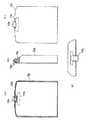
図1から図5は本発明の実施の形態1に係り、図1はユニット本体の概略構成を示す一部断面図、図2(a)はドクター装置部の側面図、(b)は同正面図、図3(a)はアシスタント装置部の内面を示す図、(b)は同一部を断面にした側面図、(c)は同外面図、(d)は同上面図、図4(a)は蓋体内面図、(b)は同一部を断面にした側面図、(c)は同背面図、(d)は同上面図、図5はドクター装置部とアシスタント装置部との装着状態を示す図である。
【0020】
図1に示すように、本発明の訪問診療用歯科治療装置は、ドクター装置部2と、蓋体12aに一体的に備えられたアシスタント装置部3と、蓋体12bとによりユニット本体1が構成されている。
【0021】
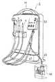
その詳細としてドクター装置部は、図2(a)〜(d)に示すように、装置枠体23の正面側壁23aにトリプルシリンジ5、マイクロモーターハンドピース又はエアタービンハンドピース6、スケーラ7等のインスツルメント8がハンガー9に引き出し自在に備えられ、その下部にトリプルシリンジ5及びエアタービンハンドピース6等に圧力水を供給するための動力電源用のプラグ20がコード21を介して電気的に接続しうるように設けられている。
【0022】
また、ドクター装置部2の装置枠体23の背面壁23bには圧力水用の貯水タンク10が備えられ、上部には持ち運び用の把手11が設けられている。
【0023】
なお、前記ハンガー9はその一端が立て方向の軸9aに支持され、軸9aはその上端がブロック9b及び正面側壁23a側に固定された支持部材9cを介して回動自在に構成されており、ドクターはハンガー9を回動してインスツルメント8を診療に好都合な位置に移動させることができるようになっている。
【0024】
また、図2(b)中の符号22は操作パネルを示し、図2(a)中の符号48は空気圧縮装置部からドクター装置部2への空気取り込み及び電源供給用の穴を示している。
【0025】
また、アシスタント装置部3は、図3(a)〜(d)に示すように、蓋体12aの内側に、排唾を空気と共に吸引誘導するバキュームホース14を連結し、このホース14にて吸引された排唾を気液分離するためのセパレータ部13が蓋体12aの内壁に固定され、セパレータ部13の下面にはセパレータ部13に吸引装置、例えば家庭用電気掃除機等を装着する吸引ホース17が連結されている。
【0026】
そして、バキュームホース14の端部には図示しない吸引ノズルを着脱自在に装着する装着口15が設けられ、装着口15はセパレータ部13上端に支持杆16a介して支持されたハンガー16に係脱自在に係止されており、一方、セパレータ部13の下面には吸引ホース17が接続され、その開放端には例えば家庭用掃除機等の吸引装置を着脱自在に装着する装着口19が設けられている。
【0027】
またセパレータ部13内には点線にて示すようにセパレータタンク24が載置されており、接続された図示しない吸引装置の吸引力にてセパレータタンク24内の空気が吸引されることにより排唾がバキュームホース14を経て、ノズル25から空気と共にセパレータタンク24内に排出される。この時、気液が分離されて排唾26はセパレータタンク24内に溜まり、空気27はセパレータタンク24の上部から吸引ホース17を経て図示しない吸引装置の排出口から大気中に放出される。
【0028】
更に、前記セパレータ部13は、その前面に蝶番29を介して開閉自在な扉28が設けられており、セパレータタンク24に溜まった排唾26は扉28を開けてセパレータタンク24と共に取り出し、処分することができるようになっている。
【0029】
なお、図3中の符号11aはアシスタント装置部3をドクター装置部2から分離して持ち運びすることができるようにした細長凹形状の把手を示し、18aはドクター装置部2の係止突起18cに係止する係止フックを示す。そしてアシスタント装置部3のドクター装置部2に対する装着は、図1に示すようにアシスタント装置部3の低部4aをドクター装置部2の座部4bに載置すると共にアシスタント装置部3の係合縁49a(図3)をドクター装置部2の係合縁48bに係合し、上部の掛止フック18aと18c間を掛止して一体化することができるようになっている。
また、吸引装置は家庭用掃除機に限らずバキュームモータを用いてもよい。
【0030】
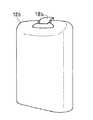
一方、蓋体12bは、図4(a)から(d)に示すように、上部にドクター装置部2から分離して持ち運びすることができるようにした細長凹形状の把手11bが設けられ、更に、頂部にはドクター装置部2の係止突起18cに係止する係止フック18bが設けられていて、ドクター装置部2の正面、即ちインスツルメント8が設けられた側を覆うことができるようになっている。
【0031】
この場合、蓋体12bのドクター装置部2に対する装着は、図1に示すように蓋体12bの低部4cをドクター装置部2の座部4dに載置すると共に蓋体12bの係合縁49b(図4)をドクター装置部2の係合縁48aに係合し、上部の掛止フック18bと18c間を掛止して一体化することができるようになっている。
【0032】
以上の構成のアシスタント装置部3をドクター装置部2の背面、即ち貯水タンク10側に装着した場合に、ドクター装置部2側に備えられた貯水タンク10とアシスタント装置部3側に備えられたセパレータ部13との相対的位置関係は、図5に示すように左右の空間を補完し合い、また貯水タンク10とバキュームホース14とは重なり合った状態にて装着が可能となっている。
【0033】
実施の形態1によれば、訪問診療用歯科治療装置をドクター装置部2とアシスタント装置部3とに分離し、かつ両者間を着脱自在なユニット本体1に構成したことにより、ドクター装置部2とアシスタント装置部3とを一体化し、ユニットとして搬送することが可能になると共に、歯科治療時には前記両者間を分離してドクター装置部2をドクター側に、アシスタント装置部3をアシスタント側に配置することが可能となり、アシスタント用具を患者越しに使用しなくてもよくなる。
【0034】
(実施の形態2)
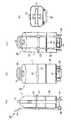
図6(a)から(d)は本発明の実施の形態2に係り、図6(a)は搬送車に本発明の訪問診療用歯科治療装置を積載した側面図、(b)は同正面図、(c)は同背面図、(d)は同上面図である。
【0035】
本実施の形態は、本発明の訪問診療用歯科治療装置を専用搬送車に積載して搬送することを可能に構成したものである。
【0036】
専用搬送車36は図に示すように、荷台37の下面に一対の車輪38が設けられ、荷台37の一端から上方に向かって運搬用把手39が立設されたキャリーカートである。
【0037】
一方、本実施の形態における本発明の訪問診療用歯科治療装置は、前記実施の形態1にて説明したドクター装置部2とアシスタント装置3から成るユニット本体1と空気圧縮装置部35とに分離して積み重ね可能に構成され、このユニット本体1と空気圧縮装置部35とをキャリーカート36の荷台37に積んで搬送する際に積み荷がづれないようにするために、ユニット本体1と空気圧縮装置部35とキャリーカート36の荷台37との重ね合わせ面相互間に凹凸形状が係合し合うずれ止め防止用の係止部40,41が設けられ、更に運搬用把手39の略中央にはユニット本体1を側面から締めつけて積み荷の倒れを防止するベルト42が設けられている。なお、ベルト42はバックル43を介して係脱自在である。
【0038】
また、荷台37の前方には荷台37を水平に保つ支持脚44が設けられている。
【0039】
実施の形態2によれば、訪問先に出向く際にユニット本体1及び空気圧縮装置部35を院内の所定の位置から屋外の運搬車両まで、あるいは訪問先にて運搬車両から患者の住居まで等の間をキャリーカート36にて搬送することが可能となり、キャリーカート36が使用できない短距離のみを手で持ち運べばよいことになるので搬送が容易になる。
【0040】
また、ユニット本体1と空気圧縮装置部35及び空気圧縮装置部35とキャリーカート36の荷台37相互間がずれ止め40,41にて係合され、しかもユニット本体1の側面がベルト42にてキャリーカート36の運搬用把手39に掛止されているので、荷積み操作が容易であると共に積み荷のずれや倒れが防止され、搬送が安全かつ容易になる。
【0041】
更に、空気圧縮装置部35がドクター装置部2から分離されているので、空気圧縮装置部35を患者から離れた位置に配置することができ、運転による騒音を避けることが可能となる。
【0042】
(実施の形態3)
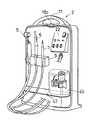
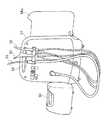
図7から図10は本発明の実施の形態3に係り、図7はドクター装置部に空気圧縮装置を備えた斜視図、図8はアシスタント装置部の正面を示す斜視図、図9は蓋体の背面を示す斜視図、図10は空気圧縮装置を引き出した状態を示す斜視図である。
【0043】
本実施の形態では、前記実施の形態1において空気圧縮装置部35をドクター装置部2から切り離して両者を積み重ね可能に構成したことに替えて、図7に示すように空気圧縮装置部45をドクター装置部2のパネル22下方の台板47上に装脱自在に設けた例を示すものである。
【0044】
そして、図7から図9に示すように、ドクター装置部2の正面は前記実施の形態1と同様に蓋体12bにて覆われ、ドクター装置部2の背面は内面にアシスタント装置部3が設けられた蓋体12aにて覆われている。一方、空気圧縮装置部45は図10に示すように長いホース46を介してドクター装置部2に接続されている。これにより空気圧縮装置45はドクター装置部2から外して患者から離れた位置に配置することが可能となっている。
【0045】
また、ドクター装置部2の上部には把手11が設けられており、ドクター装置部2の背面にはアシスタント装置部3が内蔵された蓋体12aが、正面には蓋体12bが前記実施の形態1と同様に係止フック18a,18b及び係止突起18cを介して着脱自在に装着可能であり、一体化して持ち運ぶことが可能となっている。また、ドクター装置部2の下面と前記実施の形態2におけるキャリーカート36の荷台37相互間には、係合して位置ずれを防止する図示しない凹凸形状のずれ止めが形成され、ユニット本体1が倒れないように側面が図示しないベルトを介してキャリーカート36の運搬用把手39に締めつけられ、安全に搬送することが可能となっている。
【0046】
実施の形態3によれば、空気圧縮装置部45をドクター装置部2内に長いホース46を介して装脱自在に設けたことにより、空気圧縮装置部45をドクター装置部2から外して患者から離れた位置、例えば屋外等に配置することができ、空気圧縮装置部45の運転による騒音を避けることが可能となる。更に、キャリーカート36にて安全かつ容易に搬送することが可能である。
【0047】
【発明の効果】
以上説明したように本発明によれば、訪問診療用歯科治療装置を構成するユニット本体をドクター装置部とアシスタント装置部とに分離しかつその相互間を着脱自在に構成したことにより、訪問治療の際にその相互間を一体的に結合して搬送し、治療時には前記両者間を分離してドクター装置部をドクター側に、アシスタント装置部をアシスタント側に配置することが可能となり、アシスタントはアシスタント用具を患者越しに使用しなくてもよくなる。
【0048】
また、ユニット本体と空気圧縮装置部とを分離し、積み重ねて専用搬送車にて搬送することを可能に構成したことにより、搬送が安全かつ容易になると共に、空気圧縮装置部がユニット本体から分離されているので空気圧縮装置部を患者から離れた位置に配置することができ運転の騒音を避けることが可能となる。
【0049】
更に、空気圧縮装置部をドクター装置部に対し長いホースを介して装脱自在に設けることにより、患者から離れた位置に配置することが可能となり、空気圧縮装置部の運転による騒音を避けて診療をすることが可能となる。また、装置全体を搬送車にて搬送可能な構成にしたことにより、搬送が安全かつ容易になる。
【図面の簡単な説明】
【図1】本発明の実施の形態1に係るユニット本体の概略構成を示す一部断面図である。
【図2】(a)はドクター装置部の側面図、(b)は同正面図である。
【図3】(a)はアシスタント装置部の内面を示す図、(b)は一部を断面にした側面図、(c)は同外面図、(d)は同上面図である。
【図4】(a)は蓋体内面図、(b)は一部を断面にした側面図、(c)は同外面図、(d)は同上面図である。
【図5】ドクター装置部とアシスタント装置部との装着状態を示す図である。
【図6】本発明の実施の形態2に係り(a)は搬送車に本発明のユニット本体を積載した側面図、(b)は同正面図、(c)は同背面図、(d)は同上面図である。
【図7】本発明の実施の形態3に係るドクター装置部に空気圧縮装置を備えた斜視図である。
【図8】アシスタント装置部の正面を示す斜視図である。
【図9】蓋体の背面を示す斜視図である。
【図10】空気圧縮装置を引き出した状態を示す斜視図である。
【図11】従来の治療装置を示す斜視図である。
【図12】従来の治療装置を示す斜視図である。[0001]
BACKGROUND OF THE INVENTION
The present invention relatesto a dental treatment apparatus for visit medical treatmentconstituted by a unit main body comprising adoctor apparatussection havinga doctor tool such as a dental treatment handpiece and anassistant apparatus having a suction apparatus such as a vacuum tube for salivation. About.
[0002]
[Prior art]
As a conventional dental treatment apparatus for home visit medical treatment, a dental treatment unit for home visits disclosed in JP-A-8-196554 and JP-A-9-140733 is known. As shown in FIG. 11, these dental treatment units have a
[0003]
The
[0004]
[Problems to be solved by the invention]
However, since the conventional dental treatment apparatus for visiting medical treatment has a suction device integrally formed in the treatment apparatus, the doctor places the treatment apparatus at his / her hand when performing dental treatment at the visit destination. In order to use handpieces etc., there is a problem that the assistant located on the opposite side across the patient must pull out the saliva discharger from the treatment device arranged on the doctor side and use it over the patient there were. In addition, the treatment apparatus is provided with a handle so that it can be carried, but it has a problem that it is not easy to carry because it is a heavy object.
[0005]
Therefore, the present invention has been made in view of the above-mentioned problems, and during dental treatment at a visited place, medical treatment can be performed without crossing the patient's clinical flow of the doctor and assistant, and medical treatment can be performed without causing discomfort to the patient. It is an object of the present invention to provide a dental treatment apparatus for visiting medical care that can improve efficiency.
[0006]
[Means for Solving the Problems]
In order to achieve the above-mentioned object, the invention of claim 1 according to the present invention comprisesa doctor device part provided with a doctor tool such as adental treatment handpiece and an assistant device part provided with an assistant tool such as a vacuum tube for salivation. In the dental treatment apparatus for visit medical treatment that is configured so that both the unit body and the device unit of the unit body and the assistant device part of the unit body are integrated at the time of transportation and can be divided at the time of use. The doctor device unit and the assistant device unit include a
[0007]
According to the first aspect of the present invention, the unit main body is configured so that the doctor device part and the assistant device part can be divided, so that the doctor device part is separated from the doctor side when performing medical care at a visited place. In addition, the assistant device portion can be arranged on the assistant side, and the assistant does not have to use the assistant tool over the patient.
[0008]
In particular, the
[0010]
The
[0012]
Further, the
[0014]
In addition, the
[0016]
The invention of
[0017]
According to the invention of
[0018]
DETAILED DESCRIPTION OF THE INVENTION
Hereinafter, embodiments of the present invention will be described with reference to the drawings.
In addition, in each embodiment, the common summary attaches | subjects a common code | symbol and respond | corresponds, and the overlapping description is abbreviate | omitted.
[0019]
(Embodiment 1)
1 to 5 relate to a first embodiment of the present invention, FIG. 1 is a partial cross-sectional view showing a schematic configuration of a unit main body, FIG. 2A is a side view of a doctor device, and FIG. 3A isa diagram showing the inner surface of the assistant device, FIG .3B is a side view of the same section, FIG. 3C is the outer view, FIG. 3D is the top view, and FIG. ) Is an inside view of the lid, (b) is a side view with the same section in cross section, (c) is a rear view thereof, (d) is a top view thereof, and FIG. 5 is a wearing state of the doctor device section and the assistant device section. FIG.
[0020]
As shown in FIG. 1, the dental treatment apparatus for home-visit treatment according to the present invention includes a unit body 1 including a
[0021]
As shown in detail in FIG. 2 (a) to (d), the doctor device unit includes a
[0022]
In addition, a
[0023]
One end of the hanger 9 is supported by a shaft 9a in the upright direction, and the shaft 9a is configured to be rotatable through a support member 9c whose upper end is fixed to the
[0024]
Further,
[0025]
Further, as shown in FIGS. 3A to 3D, the
[0026]
An
[0027]
A
[0028]
Further, the
[0029]
In FIG. 3,
The suction device is not limited to a household vacuum cleaner, and a vacuum motor may be used.
[0030]
On the other hand, as shown in FIGS. 4 (a) to 4 (d), the
[0031]
In this case, as shown in FIG. 1, the
[0032]
When the
[0033]
According to the first embodiment, the dental treatment device for home-visit treatment is separated into the
[0034]
(Embodiment 2)
FIGS. 6 (a) to 6 (d) relate to the second embodiment of the present invention, FIG. 6 (a) is a side view in which a dental treatment apparatusfor visiting medical care of the present invention is loaded on a transport vehicle, and FIG. FIG. 3C is a rear view of the same, and FIG.
[0035]
In the present embodiment, the dental treatment apparatus for visit medical treatment according to the present invention can be loaded and transported on a dedicated transport vehicle.
[0036]
As shown in the figure, the
[0037]
On the other hand, the dental treatment apparatus for visit medical treatment according to the present inventionin the present embodiment is separated into theunit main body 1 and the air compressing
[0038]
A
[0039]
According to the second embodiment, theunit main body 1 and the
[0040]
Further, theunit body 1 and the
[0041]
Furthermore, since the
[0042]
(Embodiment 3)
7 to 10 relate to
[0043]
In this embodiment, the
[0044]
Then, as shown in FIGS. 7 to 9, the front surface of the
[0045]
Further, a
[0046]
According to the third embodiment, the
[0047]
【The invention's effect】
As described above, according to the present invention,the unit main bodyconstituting the dental treatment device for visiting medical care is separated into the doctor device portion and the assistant device portion, and is configured to be detachable between them, so that At the time of treatment, it is possible to connect the two together so that they can be separated and separated from each other, and the doctor device can be placed on the doctor side and the assistant device can be placed on the assistant side. Does not have to be used by patients.
[0048]
In addition, theunit body and the air compressor unit can be separated, stacked, and transported by a dedicated transport vehicle, making the transport safer and easier and the air compressor unit separated from theunit body. Therefore, the air compressor unit can be arranged at a position away from the patient, and driving noise can be avoided.
[0049]
Furthermore, by providing the air compressor unit detachably with a long hose with respect to the doctor device unit, it is possible to place it at a position away from the patient, and avoid the noise caused by the operation of the air compressor unit. It becomes possible to do. In addition, since the entire apparatus can be transported by a transport vehicle, transport is safe and easy.
[Brief description of the drawings]
FIG. 1 is a partial cross-sectional view showing a schematic configuration of a unit body according to Embodiment 1 of the present invention.
FIG. 2A is a side view of a doctor device, and FIG. 2B is a frontview thereof .
3A is a view showing the inner surface of the assistant device section, FIG. 3B is a side view with a partial cross section, FIG. 3C is the same outer view, and FIG.
4A is an inner surface view of a lid body, FIG. 4B is a side view with a partial cross section, FIG. 4C is an outer surface view thereof, and FIG.
FIG. 5 is a diagram showing a wearing state of the doctor device unit and the assistant device unit.
6A is a side view in which aunit main body of the present invention is loaded on a transport vehicle according to a second embodiment of the present invention, FIG. 6B is a front view thereof, FIG. 6C is a rear view thereof, and FIG. Is a top view of the same.
FIG. 7 is a perspective view including an air compression device in a doctor device section according to a third embodiment of the present invention.
FIG. 8 is a perspective view showing the front of the assistant device.
FIG. 9 is a perspective view showing the back surface of the lid.
FIG. 10 is a perspective view showing a state in which the air compressor is pulled out.
FIG. 11 is a perspective view showing a conventional treatment apparatus.
FIG. 12 is a perspective view showing a conventional treatment apparatus.
Claims (2)
Translated fromJapanese前記ドクター装置部とアシスタント装置部は、把手11を備えるドクター装置部2の装置枠体23と、この枠体23の正面側に蓋体12b、背面側にアシスタント装置部3を構成する蓋体12aをそれぞれ被覆自在に装着し、かつ両蓋体12a,12bに取付けた係止フック18a,18bを前記装置枠体23の把手11側に取付けた係止突起18cに係止することができるように構成するとともに前記ドクター装置部2は、前記装置枠体23の正面側壁23aにトリプルシリンジ5等のインスツルメント8をハンガー9を介して引き出し自在に備え、かつ前記正面側壁23aの下部23cに前記インスツルメント8に動力電源を供給するための電源用プラグ20をコード21を介して電源部に電気的に接続しうるように構成し、さらに前記アシスタント装置部3は、前記蓋体12aに、排唾を空気と共に吸引誘導するバキュームホース14を連結しこのホース14にて吸引した排唾を気液分離するセパレータ部13を配備すると共に、前記セパレータ部13の下面に前記セパレータ部13を吸引装置に接続する吸引ホース17を装備することにより構成したことを特徴とする訪問診療用歯科治療装置。A unit main body is constituted by a doctor device portion having a doctor tool such as a dental treatment handpiece and an assistant device portion having an assistant tool such as a saliva discharge vacuum tube, and the doctor device portion and the assistant device of the unit main body. In the dental treatment apparatus for visit medical treatment configured so that both the device unit and the unit can be integrated at the time of transportation and can be divided at the time of use,
The doctor device unit and the assistant device unit include a device frame 23 of the doctor device unit 2 including the handle 11, a lid 12 b that configures the lid 12 b on the front side of the frame 23 and the assistant device 3 on the back side. So that the hooks 18a and 18b attached to the lids 12a and 12b can be locked to the locking projections 18c attached to the handle 11 side of the device frame 23. The doctor device unit 2 includes an instrument 8 such as a triple syringe 5 that can be pulled out through a hanger 9 on the front side wall 23a of the device frame 23, and the lower side 23c of the front side wall 23a A power plug 20 for supplying power to the instrument 8 is configured to be electrically connected to a power supply unit via a cord 21, and The stationary device unit 3 is connected to the lid body 12a with a vacuum hose 14 for sucking and sucking saliva together with air, and a separator unit 13 for separating the saliva sucked by the hose 14 from gas and liquid. A dental treatment apparatus for visiting medical treatment characterized by comprising a suction hose 17 for connecting the separator part 13 to a suction device on the lower surface of the part 13.
Priority Applications (1)
| Application Number | Priority Date | Filing Date | Title |
|---|---|---|---|
| JP2000364777AJP4674734B2 (en) | 2000-11-30 | 2000-11-30 | Dental treatment equipment for visiting clinics. |
Applications Claiming Priority (1)
| Application Number | Priority Date | Filing Date | Title |
|---|---|---|---|
| JP2000364777AJP4674734B2 (en) | 2000-11-30 | 2000-11-30 | Dental treatment equipment for visiting clinics. |
Publications (2)
| Publication Number | Publication Date |
|---|---|
| JP2002165817A JP2002165817A (en) | 2002-06-11 |
| JP4674734B2true JP4674734B2 (en) | 2011-04-20 |
Family
ID=18835658
Family Applications (1)
| Application Number | Title | Priority Date | Filing Date |
|---|---|---|---|
| JP2000364777AExpired - Fee RelatedJP4674734B2 (en) | 2000-11-30 | 2000-11-30 | Dental treatment equipment for visiting clinics. |
Country Status (1)
| Country | Link |
|---|---|
| JP (1) | JP4674734B2 (en) |
Families Citing this family (6)
| Publication number | Priority date | Publication date | Assignee | Title |
|---|---|---|---|---|
| JP4997539B2 (en)* | 2008-03-13 | 2012-08-08 | 株式会社長田中央研究所 | Dental treatment unit for home visits |
| JP2012152486A (en)* | 2011-01-28 | 2012-08-16 | Osada Res Inst Ltd | Carry bag and cart for house call |
| JP2013085594A (en)* | 2011-10-14 | 2013-05-13 | Yoshida Dental Mfg Co Ltd | Movable dental treatment device |
| JP5864245B2 (en)* | 2011-12-20 | 2016-02-17 | 長田電機工業株式会社 | Portable unit for dental hygienist |
| JP5785901B2 (en)* | 2012-05-10 | 2015-09-30 | 株式会社モリタ製作所 | Dental care equipment for home visits |
| JP6736246B2 (en)* | 2014-01-31 | 2020-08-05 | 株式会社吉田製作所 | Portable dental treatment equipment |
Family Cites Families (5)
| Publication number | Priority date | Publication date | Assignee | Title |
|---|---|---|---|---|
| JPS5570247A (en)* | 1978-11-20 | 1980-05-27 | Sakana Sangyo Kk | Instrument box for dental visit |
| JPS6081519U (en)* | 1983-11-09 | 1985-06-06 | 長田電機工業株式会社 | Dental unit for house calls |
| JPH0236497Y2 (en)* | 1984-10-24 | 1990-10-04 | ||
| JPH0975377A (en)* | 1995-09-13 | 1997-03-25 | Osada Res Inst Ltd | Dental treatment unit for sick visit |
| JP3217668B2 (en)* | 1995-11-24 | 2001-10-09 | 株式会社長田中央研究所 | Home visit dental treatment unit |
- 2000
- 2000-11-30JPJP2000364777Apatent/JP4674734B2/ennot_activeExpired - Fee Related
Also Published As
| Publication number | Publication date |
|---|---|
| JP2002165817A (en) | 2002-06-11 |
Similar Documents
| Publication | Publication Date | Title |
|---|---|---|
| RU2539415C2 (en) | Vacuum-generating user's portable device for medical applications | |
| RU2543042C2 (en) | Vacuum extractor put on user's body for medical applications | |
| JP2020096845A (en) | Mobility assistance devices | |
| US8770971B2 (en) | Mobile surgical dental chair and method of manufacture | |
| US9241580B2 (en) | Body transport apparatus with integrated handles | |
| US4696420A (en) | Oxygen carrier | |
| CA2452153A1 (en) | Portable cleaning assembly | |
| JP4674734B2 (en) | Dental treatment equipment for visiting clinics. | |
| CN210542256U (en) | ECMO transfer car (buggy) | |
| JP2025116256A (en) | Negative pressure shield device | |
| US20140097597A1 (en) | Transport chair allowing transport of multiple passengers | |
| JP2002017784A (en) | Patient carrier device | |
| US6941597B2 (en) | Holding device for medical instruments at a patient's bed | |
| JP5894544B2 (en) | Home visit dental care device | |
| JP2004351123A (en) | Carrying bed | |
| JP3511282B2 (en) | Clean patient transport container | |
| JPH0975377A (en) | Dental treatment unit for sick visit | |
| US5279589A (en) | IV bag with a neck strap | |
| US5970529A (en) | Bedside commode apparatus | |
| US20060153697A1 (en) | Fluid provider assembly and portable fluid provider system including same | |
| JP2003010254A (en) | Wheelchair for care/medical treatment having legless chair | |
| CN209645082U (en) | A kind of field operation unit | |
| WO2022058701A1 (en) | Isolation apparatus | |
| JPH0746251Y2 (en) | Multifunctional wheelchair for hospital | |
| JP3069570U (en) | Dental visit treatment car |
Legal Events
| Date | Code | Title | Description |
|---|---|---|---|
| A621 | Written request for application examination | Free format text:JAPANESE INTERMEDIATE CODE: A621 Effective date:20071112 | |
| A131 | Notification of reasons for refusal | Free format text:JAPANESE INTERMEDIATE CODE: A131 Effective date:20100915 | |
| A521 | Request for written amendment filed | Free format text:JAPANESE INTERMEDIATE CODE: A523 Effective date:20101111 | |
| TRDD | Decision of grant or rejection written | ||
| A01 | Written decision to grant a patent or to grant a registration (utility model) | Free format text:JAPANESE INTERMEDIATE CODE: A01 Effective date:20101220 | |
| A01 | Written decision to grant a patent or to grant a registration (utility model) | Free format text:JAPANESE INTERMEDIATE CODE: A01 | |
| A61 | First payment of annual fees (during grant procedure) | Free format text:JAPANESE INTERMEDIATE CODE: A61 Effective date:20110119 | |
| FPAY | Renewal fee payment (event date is renewal date of database) | Free format text:PAYMENT UNTIL: 20140204 Year of fee payment:3 | |
| R150 | Certificate of patent or registration of utility model | Ref document number:4674734 Country of ref document:JP Free format text:JAPANESE INTERMEDIATE CODE: R150 Free format text:JAPANESE INTERMEDIATE CODE: R150 | |
| R250 | Receipt of annual fees | Free format text:JAPANESE INTERMEDIATE CODE: R250 | |
| R250 | Receipt of annual fees | Free format text:JAPANESE INTERMEDIATE CODE: R250 | |
| R250 | Receipt of annual fees | Free format text:JAPANESE INTERMEDIATE CODE: R250 | |
| R250 | Receipt of annual fees | Free format text:JAPANESE INTERMEDIATE CODE: R250 | |
| R250 | Receipt of annual fees | Free format text:JAPANESE INTERMEDIATE CODE: R250 | |
| R250 | Receipt of annual fees | Free format text:JAPANESE INTERMEDIATE CODE: R250 | |
| LAPS | Cancellation because of no payment of annual fees |