JP4673654B2 - Side trunk locking device for motorcycles - Google Patents
Side trunk locking device for motorcyclesDownload PDFInfo
- Publication number
- JP4673654B2 JP4673654B2JP2005101933AJP2005101933AJP4673654B2JP 4673654 B2JP4673654 B2JP 4673654B2JP 2005101933 AJP2005101933 AJP 2005101933AJP 2005101933 AJP2005101933 AJP 2005101933AJP 4673654 B2JP4673654 B2JP 4673654B2
- Authority
- JP
- Japan
- Prior art keywords
- catch
- trunk
- striker
- main part
- lid member
- Prior art date
- Legal status (The legal status is an assumption and is not a legal conclusion. Google has not performed a legal analysis and makes no representation as to the accuracy of the status listed.)
- Expired - Fee Related
Links
Images


Classifications
- B—PERFORMING OPERATIONS; TRANSPORTING
- B62—LAND VEHICLES FOR TRAVELLING OTHERWISE THAN ON RAILS
- B62J—CYCLE SADDLES OR SEATS; AUXILIARY DEVICES OR ACCESSORIES SPECIALLY ADAPTED TO CYCLES AND NOT OTHERWISE PROVIDED FOR, e.g. ARTICLE CARRIERS OR CYCLE PROTECTORS
- B62J9/00—Containers specially adapted for cycles, e.g. panniers or saddle bags
- B62J9/20—Containers specially adapted for cycles, e.g. panniers or saddle bags attached to the cycle as accessories
- B62J9/23—Containers specially adapted for cycles, e.g. panniers or saddle bags attached to the cycle as accessories above or alongside the rear wheel
- B—PERFORMING OPERATIONS; TRANSPORTING
- B62—LAND VEHICLES FOR TRAVELLING OTHERWISE THAN ON RAILS
- B62J—CYCLE SADDLES OR SEATS; AUXILIARY DEVICES OR ACCESSORIES SPECIALLY ADAPTED TO CYCLES AND NOT OTHERWISE PROVIDED FOR, e.g. ARTICLE CARRIERS OR CYCLE PROTECTORS
- B62J9/00—Containers specially adapted for cycles, e.g. panniers or saddle bags
- B62J9/30—Containers specially adapted for cycles, e.g. panniers or saddle bags characterised by locking arrangements, e.g. top case locks integrated in a vehicle central locking system
- Y—GENERAL TAGGING OF NEW TECHNOLOGICAL DEVELOPMENTS; GENERAL TAGGING OF CROSS-SECTIONAL TECHNOLOGIES SPANNING OVER SEVERAL SECTIONS OF THE IPC; TECHNICAL SUBJECTS COVERED BY FORMER USPC CROSS-REFERENCE ART COLLECTIONS [XRACs] AND DIGESTS
- Y10—TECHNICAL SUBJECTS COVERED BY FORMER USPC
- Y10T—TECHNICAL SUBJECTS COVERED BY FORMER US CLASSIFICATION
- Y10T292/00—Closure fasteners
- Y10T292/23—Cross bars
- Y10T292/243—Vehicle door latches
Landscapes
- Engineering & Computer Science (AREA)
- Mechanical Engineering (AREA)
- Lock And Its Accessories (AREA)
Description
Translated fromJapanese本発明は、自動二輪車の車体後部の両側に配設されるサイドトランクの蓋部材を、その閉鎖状態でロック可能なロック装置の改良に関する。 The present invention relates to an improvement in a locking device capable of locking side trunk lid members disposed on both sides of a rear body of a motorcycle in a closed state.
蓋部材に一対のストライカが設けられ、それらのストライカにそれぞれ係合して回動することを可能としたキャッチをそれぞれ有する一対のキャッチ機構が、ロック状態およびアンロック状態を遠隔操作で同時に切換えることを可能としてトランク主部側に設けられるロック装置が、たとえば特許文献1で既に知られている。
ところが上記特許文献1で開示されたロック装置では、単一の直線状に延びる回動軸に一対のキャッチが取付けられており、両キャッチの回動軸線が同軸上に限定されてしまい、一対のキャッチ機構のレイアウトに制限が生じてしまう。 However, in the locking device disclosed in Patent Document 1, a pair of catches are attached to a single linearly extending rotation shaft, and the rotation axis of both catches is limited to be coaxial, so There will be a restriction on the layout of the catch mechanism.
本発明は、かかる事情に鑑みてなされたものであり、複数のキャッチ機構のレイアウト上の自由度を増大した自動二輪車用サイドトランクのロック装置を提供することを目的とする。 The present invention has been made in view of such circumstances, and an object of the present invention is to provide a side trunk locking device for a motorcycle that increases the degree of freedom in layout of a plurality of catch mechanisms.
上記目的を達成するために、請求項1記載の発明は、車体後部の左右に配設される函状のトランク主部に開閉可能に取付けられて該トランク主部とともにサイドトランクを構成する蓋部材に複数のストライカが設けられ、各ストライカにそれぞれ係合して回動することを可能としたキャッチをそれぞれ有する複数のキャッチ機構が、前記キャッチに前記ストライカを係合せしめて蓋部材の閉鎖位置を維持するロック状態ならびに前記ストライカおよび前記キャッチの係合解除を許容して前記蓋部材の開放を可能とするアンロック状態を遠隔操作で同時に切換えることを可能として、前記トランク主部側に設けられる自動二輪車用サイドトランクのロック機構において、複数の前記キャッチ機構のキャッチが、それらのキャッチに個別に対応した複数の枢軸を介して前記トランク主部側に回動自在に支承されると共に、該複数のキャッチ機構が、それらのキャッチ機構のロック状態およびアンロック状態を同時に切換えるようにして連結ロッドで相互に連結されることを特徴とし、また請求項2記載の発明は、車体後部の左右に配設される函状のトランク主部に開閉可能に取付けられて該トランク主部とともにサイドトランクを構成する蓋部材に複数のストライカが設けられ、各ストライカにそれぞれ係合して回動することを可能としたキャッチをそれぞれ有する複数のキャッチ機構が、前記キャッチに前記ストライカを係合せしめて蓋部材の閉鎖位置を維持するロック状態ならびに前記ストライカおよび前記キャッチの係合解除を許容して前記蓋部材の開放を可能とするアンロック状態を遠隔操作で同時に切換えることを可能として、前記トランク主部側に設けられる自動二輪車用サイドトランクのロック装置において、前記複数のキャッチ機構が前記トランク主部側の共通な板状のブラケットに支持され、前記複数のキャッチ機構のキャッチが、それらのキャッチに個別に対応した複数の枢軸を介して前記共通な板状のブラケットに回動自在に支承されることを特徴とする。In order to achieve the above object, a first aspect of the present invention is a lid member that is openably and closably attached to a box-shaped trunk main portion disposed on the left and right of the rear portion of the vehicle body and forms a side trunk together with the trunk main portion. A plurality of catch mechanisms provided with a plurality of strikers, each of which has a catch that allows each striker to be engaged and rotated, maintain the closed position of the lid member by engaging the striker with the catch. A motorcycle provided on the trunk main portion side, capable of simultaneously switching by a remote operation a locked state in which the striker and the catch are disengaged and an unlocked state in which the lid member can be opened is permitted. In the side trunk locking mechanism, the catches of a plurality of the catch mechanisms individually correspond to the catches.While being rotatably supported on the trunk main part side via a plurality ofpivot, the plurality of the catch mechanism, to each other through a connecting rod so as to switch the locked state and the unlocked state of their catch mechanism at the same time The invention according to claim 2 is characterized in that the lid is configured to be openable and closable attached to a box-shaped trunk main part disposed on the left and right of the rear part of the vehicle body, and forms a side trunk together with the trunk main part. The member is provided with a plurality of strikers, and a plurality of catch mechanisms each having a catch capable of engaging and rotating with each striker respectively engage the striker with the catch so that the lid member is closed. An unlocked state that allows the lid member to be opened by allowing the locked state to be maintained and disengaging the striker and the catch. In a locking device for a motorcycle side trunk provided on the trunk main part side, the plurality of catch mechanisms are supported by a common plate-like bracket on the trunk main part side. The catches of the plurality of catch mechanisms are rotatably supported on the common plate-like bracket via a plurality of pivots individually corresponding to the catches .
また請求項3記載の発明は、請求項1又は2に記載の発明の構成に加えて、複数の前記キャッチ機構が、その高さおよび車体の車幅方向中心からの距離を相互に異ならせて配置されることを特徴とする。According to athird aspect of the invention, in addition to the configuration of the firstor second aspect of the invention, the plurality of catch mechanisms have different heights and distances from the vehicle width direction center of the vehicle body.it isdisposed.
さらに請求項4記載の発明は、請求項1〜3のいずれかに記載の発明の構成に加えて、乗車用シートの後方に配置されるグラブレールの下方に、複数の前記キャッチ機構のロック状態およびアンロック状態を切換える操作用レバーが配置されることを特徴とする。Furthermore, in addition to the structure of the invention according to any one of claims 1 to3 , the invention according to
本発明によれば、複数のキャッチ機構のキャッチが、それらのキャッチに個別に対応した複数の枢軸を介してトランク主部側に回動自在に支承されるので、複数のキャッチ機構のキャッチを同軸上に配置することが必要ではなく、各キャッチ機構のレイアウト上の自由度を増大することができる。According to thepresent invention, the catches of the plurality of catch mechanisms are rotatably supported on the trunk main part side via the plurality of pivots individually corresponding to the catches. It is not necessary to arrange it above, and the degree of freedom in layout of each catch mechanism can be increased.
また特に請求項1の発明によれば、1箇所の操作で連結ロッドを作動せしめることにより、複数のキャッチ機構のロック状態およびアンロック状態を同時に切換えることが可能となり、同期連動機構を単純化することができる。In particular, according to the invention of claim 1, by operating the connecting rod by one operation, it becomes possible to simultaneously switch the locked state and unlocked state of the plurality of catch mechanisms, thereby simplifying the synchronous interlocking mechanism. be able to.
また特に請求項2の発明によれば、複数のキャッチ機構を共通な板状のブラケットで支持することにより、複数のキャッチ機構の組付け性を高めることができ、また各キャッチ機構の支持剛性を高めて円滑な作動を保証することができる。In particular, according to the invention of claim 2, by supporting the plurality of catch mechanisms with a common plate-like bracket, it is possible to improve the assemblability of the plurality of catch mechanisms, and to increase the support rigidity of each catch mechanism. High and smooth operation can be guaranteed.
また特に請求項3の発明によれば、複数のキャッチ機構の高さおよび車体の車幅方向中心からの距離が相互に異なって設定されることにより、蓋部材の形状の自由度ならびに蓋部材へのストライカの取付け位置の設定自由度を増大することができる。Inparticular , according to the invention of
また特に請求項4の発明によれば、操作用レバーを目立たない位置に配置することができ、外観性も良好となる。Inparticular , according to the invention of
以下、本発明の実施形態を、添付図面に示した本発明の一実施例に基づいて説明する。 Embodiments of the present invention will be described below based on one embodiment of the present invention shown in the accompanying drawings.
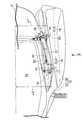
図1〜図14は本発明の一実施例を示すものであり、図1は自動二輪車の側面図、図2は図1の2矢視図、図3は図2の3矢視図、図4はロック状態での図3の4−4線断面図、図5は図4の5−5線断面図、図6はキャッチの平面図、図7はカムプレートの平面図、図8は駆動部材の平面図、図9は図8の9矢視図、図10はスライド部材の平面図、図11は図10の11矢視図、図12は図5の12−12線断面図、図13はアンロック状態での図4に対応した断面図、図14は開放操作途中での図4に対応した断面図である。 1 to 14 show an embodiment of the present invention. FIG. 1 is a side view of a motorcycle, FIG. 2 is a view taken in the direction of arrow 2 in FIG. 1, FIG. 3 is a view taken in the direction of
先ず図1において、自動二輪車の車体Bの後部には、タンデム型の乗車用シート10と、その乗車用シート10の後方に配置されるグラブレール11とが設けられるとともに、乗車用シート10の左右両側に配置されるサイドトランク12…が設けられる。両サイドトランク12…は左右対称に設けられるものであり、以下の説明では、進行方向前方を向いた状態で左側に位置するサイドトランク12についてのみ説明し、右側のサイドトランクについては説明を省略する。 First, in FIG. 1, a tandem-
図2および図3を併せて参照して、サイドトランク12は、外側方に開放するようにして車体Bの後部に取付けられる函状のトランク主部13と、そのトランク主部13の下部2箇所に設けられたヒンジ部15,15で回動可能に支承されてトランク主部13の開口端を塞ぎ得る椀状の蓋部材14とで構成されるものであり、トランク主部13および蓋部材14のいずれも硬質の合成樹脂により形成される。 2 and 3 together, the
前記蓋部材14の上部には、トランク主部13側に突出する複数たとえば一対である第1および第2ストライカ16,17が設けられており、第2ストライカ17は第1ストライカ16から前方に間隔をあけた位置に配置される。一方、トランク主部13側すなわちトランク主部13の裏面側で車体Bには、各ストライカ16,17に個別に対応した第1および第2キャッチ機構18,19が同時に作動することを可能として設けられており、第1および第2ストライカ16,17は、蓋部材14を閉じたときにトランク主部13を貫通して該トランク主部13の裏面側に突出することが可能である。 A plurality of, for example, a pair of first and
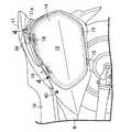
図4を併せて参照して、第1および第2キャッチ機構18,19は、第1および第2ストライカ16,17にそれぞれ係合して回動することを可能とした第1および第2キャッチ20,21をそれぞれ有するものであり、各キャッチ20,21に対応する前記ストライカ16,17を係合せしめて蓋部材14の閉鎖位置を維持するロック状態ならびに前記両ストライカ16,17および前記両キャッチ20,21の係合解除を許容して蓋部材14の開放を可能とするアンロック状態を遠隔操作で同時に切換えることが可能である。しかも第1および第2キャッチ機構18,19は、自動二輪車の前後方向に延びる板状であって車体Bに取付けられる共通なブラケット22に支持される。 Referring also to FIG. 4, the first and
さらに図5を併せて参照して、第1キャッチ機構18は、第1ストライカ16を係合し得るようにしてブラケット22に回動可能に支承される第1キャッチ20と、第1キャッチ20の回動位置を規制するようにしてブラケット22に回動可能に支承される第1カムプレート23と、操作用レバー24(図1および図4参照)に連結されるとともに該操作用レバー24の回動操作に応じて第1カムプレート23を回動駆動し得る駆動部材25と、キー操作に応じて前記駆動部材25の第1カムプレート23への連結および連結解除を切換えるようにしてブラケット22にスライド可能に支承されるスライド部材26とを備える。 Further, referring also to FIG. 5, the
図6を併せて参照して、第1キャッチ20はブラケット22の表面に摺接しつつ第1支軸27によって該ブラケット22に回動可能に支承されており、第1ストライカ16を係合可能な係止凹部28と、第1支軸27に関して係止凹部28とは反対側に位置する規制凹部29とが第1キャッチ20の外周部に設けられる。 Referring also to FIG. 6, the
図7を併せて参照して、第1カムプレート23は、ブラケット22の表面に摺接しつつ前記第1支軸27と平行な第2支軸30によって該ブラケット22に回動可能に支承されており、第1キャッチ20の規制凹部29に係合する規制突部31と、第2支軸30の半径方向に沿って長く延びる長孔状の第1ガイド孔32とが第1カムプレート23に設けられる。また第1カムプレート23および第1キャッチ20間には、規制突部31を規制凹部29に係合させるように第1カムプレート23および第1キャッチ20を付勢する第1ばね33が縮設される。 Referring also to FIG. 7, the
図8および図9を併せて参照して、駆動部材25は、第1キャッチ20および第1カムプレート23をブラケット22の表面との間に挟む位置に配置されるものであり、第1キャッチ20および第1カムプレート23に摺接しつつ前記第2支軸30で回動可能に支承される。しかも駆動部材25には、前記第1支軸27を挿通せしめる第2ガイド孔34が設けられ、この第2ガイド孔34は前記第2支軸30の軸線を中心とする円弧状に形成される。 Referring to FIGS. 8 and 9 together, the
ところで操作用レバー24は、グラブレール11の下方に配置されるものであり、グラブレール11から下方に延びてブラケット22の後部に締結される脚部11aの前方に配置され、該脚部11aの外側前端部に配置される第3支軸35により回動可能に支承される。 By the way, the
前記駆動部材25には、前記操作用レバー24に連結される連結突部56が突設されており、操作用レバー24を第3支軸35の軸線まわりに回動操作することで駆動部材25は第2ガイド孔34内での第1支軸27の位置を変化させながら第2支軸30の軸線まわりに回動することになる。而して操作用レバー24の非操作状態で駆動部材25は第2ガイド孔34の一端に第1支軸27を位置させた回動位置にあり、操作用レバー24を回動操作すると、駆動部材25は、第2支軸30の軸線まわりに図4の時計方向に回動することになる。 The
図10および図11を併せて参照して、スライド部材26は、ブラケット22の表面側に配置される第1スライド板部26aと、ブラケット22の裏面側に配置される第2スライド板部26bとを一体に有するものであり、駆動部材25の非作動状態で第1カムプレート23の第1ガイド孔32と平行な方向に延びる長孔状の第3ガイド孔36が第1スライド板部26aに設けられ、第3ガイド孔36に挿通されて第1スライド板部26aすなわちスライド部材26のスライド動作をガイドするガイドピン37がブラケット22に設けられる。また駆動部材25およびスライド部材26間には、スライド部材26を第2支軸30に近接する側に付勢するばね58が縮設される。 Referring to FIGS. 10 and 11 together, the
第2スライド板部26bの先端には、ブラケット22を貫通して第1カムプレート23の第1ガイド孔32に挿通される係合ピン38が設けられており、その係合ピン38を貫通せしめる第4ガイド孔39がブラケット22に設けられる。 An
図12において、第4ガイド孔39は、駆動部材25が非作動状態にあるときに第3ガイド孔36と平行にかつ第2支軸30の半径方向に沿って直線状に延びる第1孔部39aと、第2支軸30から離隔した第1孔部39aの一端に連なって第2支軸30の軸線を中心とする円弧状に形成される第2孔部39bと、第2支軸30に近接した第1孔部39aの他端に連なって第2支軸30の軸線を中心とする円弧状に形成される第3孔部39cとから成る。 In FIG. 12, the
ところで図1および図3で示すように、グラブレール11の前方で車体Bの左側面にはキーシリンダ錠40が設けられており、このキーシリンダ錠40に連なるケーブル41が前記スライド部材26に連結される。而して第1キャッチ機構18のロック状態で、スライド部材26は、図4で示すように、係合ピン38を第1ガイド孔32のうち第2支軸30から離隔した側の端部すなわち第4ガイド孔39における第1孔部39aの一端部に位置せしめた後退位置すなわちロック位置にあり、その状態でキーシリンダ錠40をロック位置からアンロク位置にキー操作すると、スライド部材26は、図12の鎖線で示すように係合ピン38を第1ガイド孔32のうち第2支軸30に近接した側の端部すなわち第4ガイド孔39における第1孔部39aの他端部に位置せしめるように前進した前進位置すなわちアンロック位置となる。 As shown in FIGS. 1 and 3, a
また駆動部材25には、スライド部材26が前進したアンロック位置にあるときに係合ピン38を係合させる係止凹部42が設けられており、図4で示すように、スライド部材26が後退したロック位置にあって係合ピン38が係止凹部42に係合していない状態で、駆動部材25が図4の時計方向に回動しても駆動部材25は空振りするだけであり、駆動部材25は第1カムプレート23に連結されておらず、第1カムプレート23が回動駆動されることはない。 Further, the
一方、図13で示すように、スライド部材26が前進したアンロック位置にあって係合ピン38が係止凹部42に係合している状態で、駆動部材25が図13の時計方向に回動すると、図14で示すように、第4ガイド孔39の第2孔部39c内で係合ピン38を移動させつつ第1カムプレート23が第2支軸30の軸線まわりに時計方向に回動し、それにより第1ストライカ16との係合を解除する位置まで第1キャッチ20が回動駆動されることになる。 On the other hand, as shown in FIG. 13, the
第2キャッチ機構19は、第2ストライカ17を係合し得るようにしてブラケット22に第4支軸44を介して回動可能に支承される第2キャッチ21と、第2キャッチ21の回動位置を規制するようにしてブラケット22に第5支軸45を介して回動可能に支承される第2カムプレート43とを備え、図3で示すように、第1キャッチ機構18よりも低い位置に配置される。また図2で示すように、車体Bの車幅方向中心Cおよび第1キャッチ機構18間の距離L1に比べて、車体Bの車幅方向中心Cおよび第2キャッチ機構19間の距離L2は大きく設定されるものであり、第1および第2キャッチ機構18,19は、その高さおよび車体Bの車幅方向中心Cからの距離を相互に異ならせた位置に配置されることになる。 The
第2キャッチ21は、第2ストライカ17を係合可能な係止凹部48と、第4支軸44に関して係止凹部48とは反対側に位置する規制凹部49とを外周部に有して第1キャッチ機構18の第1キャッチ20と同一形状に形成され、第2カムプレート43は、第2キャッチ21の規制凹部49に係合する規制突部50を有して第1キャッチ機構18の第1カムプレート23と同一形状に形成され、第2カムプレート43および第2キャッチ21間には、規制突部50を規制凹部49に係合させるように第2カムプレート43および第2キャッチ21を付勢する第2ばね51が縮設される。 The
而して図4で示すように、第2キャッチ21の係止凹部48に第2ストライカ17を係合せしめたロック状態で、第2カムプレート43が第5支軸45の軸線まわりに、図14で示すように時計方向に回動すると、第2キャッチ21は第2ストライカ17との係合を解除するように回動することになる。 Thus, as shown in FIG. 4, the
しかも第1および第2キャッチ機構18,19は、それらのキャッチ機構18,19のロック状態およびアンロック状態を同時に切換えるようにして連結ロッド52で相互に連結されるものであり、連結ロッド52の両端は第1キャッチ機構18の第1カムプレート23ならびに第2キャッチ機構19の第2カムプレート43を相互に連結する。また連結ロッド52の一端部は、ブラケット22における第4ガイド孔39の第2孔部39bに対応する位置にあり、第1カムプレート23の回動に応じて連結ロッド52の一端部は第2孔部39b内を移動することになる。さらに両キャッチ機構18,19がロック状態にあるときに、連結ロッド52の一端と、ブラケット22の第4ガイド孔39における一端部に位置する係合ピン38とは連結ロッド52の延長線上に並ぶ位置にあり、連結ロッド52を第1キャッチ機構18側に動かす外力が第2キャッチ機構19側から不所望に連結ロッド52に作用しても、連結ロッド52が係合ピン38に当接することで連結ロッド52の移動が阻止されることになり、第1キャッチ機構18の第1キャッチ20が第1ストライカ16との係合を解除する方向に第1カムプレート23が回動されることはない。 In addition, the first and
ところで操作用レバー24は、キーシリンダ錠40をアンロック位置側にキー操作した後にアンロック操作したときには、図8で示すように、車体Bから側方に突出した状態となるものであり、蓋部材14を閉じて第1および第2ストライカ16,17が第1および第2キャッチ18,19に係合してロック状態とならない限り、車体Bから突出したままである。またキーシリンダ錠40も、ロックが完了しない限りキーの抜き出しが阻止されるように構成されており、そのような構成とすることにより、蓋部材14が完全に閉じない限りキーが抜けないこととなるので、蓋部材14が閉まっていない状態での自動二輪車の走行が防止されることになる。 By the way, when the unlocking operation is performed after the
また自二輪車の進行方向左側に位置するサイドトランク12のトランク主部13内には、ブラケット22に第6支軸53で回動可能に支承されるシートロック解除用レバー54が突入されており、蓋部材14を開放した状態で、シートロック解除用レバー54を操作することにより、該シートロック解除用レバー54にケーブル55を介して連結されているシートロック機構(図示せず)がロック状態を解除するように作動し、それにより乗車用シート10を開放操作することが可能となる。 In addition, a seat
次にこの実施例の作用について説明すると、第1および第2キャッチ機構18,19がそれぞれ備える第1および第2キャッチ20,21は、それらのキャッチに個別に対応した第1および第4枢軸27,44を介してトランク主部13側に回動自在に支承されるので、第1および第2キャッチ20,21を同軸上に配置することが必要ではなく、第1および第2キャッチ機構18,19のレイアウト上の自由度を増大することができる。 Next, the operation of this embodiment will be described. The first and
また第1および第2キャッチ機構18,19の高さおよび車体Bの車幅方向中心Cからの距離が相互に異なって設定されており、蓋部材14の形状の自由度ならびに蓋部材14への第1および第2ストライカ16,17の取付け位置の設定自由度を増大することができる。 Further, the heights of the first and
しかも第1および第2キャッチ機構18,19が、それらのキャッチ機構18,19のロック状態およびアンロック状態を同時に切換えるようにして連結ロッド52で相互に連結されているので、1箇所の操作で連結ロッド52を作動せしめることにより、両キャッチ機構18,19のロック状態およびアンロック状態を同時に切換えることが可能となり、同期連動機構を単純化することができる。 Moreover, since the first and
また第1および第2キャッチ機構18,19は共通な板状のブラケット22に支持されるものであり、第1および第2キャッチ機構18,19の組付け性を高めることができ、各キャッチ機構18,19の支持剛性を高めて円滑な作動を保証することができる。 Further, the first and
さらに乗車用シート10の後方に配置されるグラブレール11の下方に、第1および第2キャッチ機構18,19のロック状態およびアンロック状態を切換える操作用レバー24が配置されるので、操作用レバー24を目立たない位置に配置することができ、外観性も良好となる。 Further, an
以上、本発明の実施例を説明したが、本発明は上記実施例に限定されるものではなく、特許請求の範囲に記載された本発明を逸脱することなく種々の設計変更を行うことが可能である。 Although the embodiments of the present invention have been described above, the present invention is not limited to the above-described embodiments, and various design changes can be made without departing from the present invention described in the claims. It is.
10・・・乗車用シート
11・・・グラブレール
12・・・サイドトランク
13・・・トランク主部
14・・・蓋部材
16,17・・・ストライカ
18,19・・・キャッチ機構
20,21・・・キャッチ
22・・・ブラケット
24・・・操作用レバー
27,44・・・枢軸
52・・・連結ロッド
B・・・車体DESCRIPTION OF
Claims (4)
Translated fromJapanese前記複数のキャッチ機構(18,19)のキャッチ(20,21)が、それらのキャッチ(20,21)に個別に対応した複数の枢軸(27,44)を介して前記トランク主部(13)側に回動自在に支承されると共に、該複数のキャッチ機構(18,19)が、それらのキャッチ機構(18,19)のロック状態およびアンロック状態を同時に切換えるようにして連結ロッド(52)で相互に連結されることを特徴とする自動二輪車用サイドトランクのロック装置。A lid member (14) which is openably and closably attached to a box-shaped trunk main part (13) disposed on the left and right of the rear part of the vehicle body (B) and constitutes a side trunk (12) together with the trunk main part (13) Are provided with a plurality of catch mechanisms (18, 17) each having a catch (20, 21) capable of engaging and rotating with each striker (16, 17). 19) engages the catcher (20, 21) with the striker (16, 17) to maintain the closed position of the lid member (14), and the striker (16, 17) and the catch (20, 20). 21) The trunk main part (13) can be simultaneously switched by remote operation in an unlocked state allowing the disengagement of 21) and allowing the lid member (14) to be opened. The lock device of a motorcycle side trunk provided,
Catch (20, 21) ofsaid plurality ofkeys Yatchi mechanism (18, 19) is, through said plurality of pivot individually corresponding to those of the catch (20, 21) (27,44) trunk main part (13 ), And the plurality of catch mechanisms (18, 19) can simultaneously switch the lock state and the unlock state of the catch mechanisms (18, 19). ), A side trunk locking device for a motorcycle.
前記複数のキャッチ機構(18,19)が前記トランク主部(13)側の共通な板状のブラケット(22)に支持され、
前記複数のキャッチ機構(18,19)のキャッチ(20,21)が、それらのキャッチ(20,21)に個別に対応した複数の枢軸(27,44)を介して前記共通な板状のブラケット(22)に回動自在に支承されることを特徴とする自動二輪車用サイドトランクのロック装置。A lid member (14) which is openably and closably attached to a box-shaped trunk main part (13) disposed on the left and right of the rear part of the vehicle body (B) and constitutes a side trunk (12) together with the trunk main part (13) Are provided with a plurality of catch mechanisms (18, 17) each having a catch (20, 21) capable of engaging and rotating with each striker (16, 17). 19) engages the catcher (20, 21) with the striker (16, 17) to maintain the closed position of the lid member (14), and the striker (16, 17) and the catch (20, 20). 21) The trunk main part (13) can be simultaneously switched by remote operation in an unlocked state allowing the disengagement of 21) and allowing the lid member (14) to be opened. The lock device of a motorcycle side trunk provided,
The plurality of catch mechanisms (18, 19) are supported by a common plate-like bracket (22) on the trunk main portion (13) side,
The common plate-like bracket is provided with the catches (20, 21) of the plurality of catch mechanisms (18, 19) via a plurality of pivots (27, 44) individually corresponding to the catches (20, 21). (21) A side trunk locking device for a motorcycle,which is rotatably supported by (22) .
Priority Applications (4)
| Application Number | Priority Date | Filing Date | Title |
|---|---|---|---|
| JP2005101933AJP4673654B2 (en) | 2005-03-31 | 2005-03-31 | Side trunk locking device for motorcycles |
| ES200600744AES2328760B1 (en) | 2005-03-31 | 2006-03-23 | CLOSURE DEVICE FOR MOTORCYCLE SIDE GUARD. |
| US11/391,556US7708326B2 (en) | 2005-03-31 | 2006-03-29 | Lock device for motorcycle side trunk |
| DE200610014929DE102006014929B4 (en) | 2005-03-31 | 2006-03-30 | Locking device for a motorcycle side case and motorcycle case |
Applications Claiming Priority (1)
| Application Number | Priority Date | Filing Date | Title |
|---|---|---|---|
| JP2005101933AJP4673654B2 (en) | 2005-03-31 | 2005-03-31 | Side trunk locking device for motorcycles |
Publications (2)
| Publication Number | Publication Date |
|---|---|
| JP2006281893A JP2006281893A (en) | 2006-10-19 |
| JP4673654B2true JP4673654B2 (en) | 2011-04-20 |
Family
ID=37055631
Family Applications (1)
| Application Number | Title | Priority Date | Filing Date |
|---|---|---|---|
| JP2005101933AExpired - Fee RelatedJP4673654B2 (en) | 2005-03-31 | 2005-03-31 | Side trunk locking device for motorcycles |
Country Status (4)
| Country | Link |
|---|---|
| US (1) | US7708326B2 (en) |
| JP (1) | JP4673654B2 (en) |
| DE (1) | DE102006014929B4 (en) |
| ES (1) | ES2328760B1 (en) |
Cited By (1)
| Publication number | Priority date | Publication date | Assignee | Title |
|---|---|---|---|---|
| US8844958B2 (en) | 2012-03-30 | 2014-09-30 | Honda Motor Co., Ltd | Saddle-ride type vehicle |
Families Citing this family (13)
| Publication number | Priority date | Publication date | Assignee | Title |
|---|---|---|---|---|
| JP4694315B2 (en)* | 2005-08-31 | 2011-06-08 | 川崎重工業株式会社 | Seat lock guard structure |
| ITMI20080211A1 (en)* | 2008-02-11 | 2009-08-12 | Givi Srl | "SUITCASE FOR MOTORCYCLES WITH EASY OPENING DEVICE" |
| JP5091804B2 (en)* | 2008-08-22 | 2012-12-05 | 本田技研工業株式会社 | Saddle bag mounting structure for motorcycles |
| DE102009021529A1 (en) | 2009-05-15 | 2010-11-18 | Bayerische Motoren Werke Aktiengesellschaft | Luggage container for attachment to a vehicle, in particular a motorcycle |
| JP5588701B2 (en)* | 2010-03-09 | 2014-09-10 | 本田技研工業株式会社 | Cover structure of saddle-ride type vehicle |
| JP5707290B2 (en) | 2011-09-28 | 2015-04-30 | 本田技研工業株式会社 | Saddle riding vehicle |
| DE202013011944U1 (en) | 2012-08-07 | 2015-03-11 | Givi S.R.L. Motorcycle Accessoires | Suitcases for motorcycles |
| JP6151896B2 (en)* | 2012-08-28 | 2017-06-21 | 本田技研工業株式会社 | Saddle-type vehicle routing structure |
| CN203472593U (en)* | 2013-08-15 | 2014-03-12 | 中山市隆成日用制品有限公司 | Base locking device combined with child car safety seat |
| JP5965417B2 (en) | 2014-01-07 | 2016-08-03 | 本田技研工業株式会社 | Saddle bag lock device for saddle-ride type vehicles |
| DE102016209092A1 (en)* | 2016-05-25 | 2017-11-30 | Bayerische Motoren Werke Aktiengesellschaft | Locking device for a seat of a motorcycle |
| DE102018210355A1 (en)* | 2018-06-26 | 2020-01-02 | Bayerische Motoren Werke Aktiengesellschaft | Neige vehicle |
| IT201800010026A1 (en) | 2018-11-05 | 2020-05-05 | Givi S P A | SUPPORT KIT FOR A MOTORCYCLE CASE. |
Family Cites Families (31)
| Publication number | Priority date | Publication date | Assignee | Title |
|---|---|---|---|---|
| US1794786A (en)* | 1926-10-29 | 1931-03-03 | Charles H E Remondino | Automobile hood-holding means |
| US1665642A (en)* | 1927-02-15 | 1928-04-10 | Sankey Harold Bantock | Tool holder and other receptacle for use on motor vehicles |
| US3026132A (en)* | 1959-08-28 | 1962-03-20 | Chicago Forging & Mfg Co | Dual latch structure |
| US3413025A (en)* | 1967-05-01 | 1968-11-26 | Bell Aerospace Corp | Sliding closure latch |
| US4273368A (en)* | 1979-07-06 | 1981-06-16 | American Safety Equipment Corporaion | Dual latching mechanism for a flexible deck lid |
| JPS6136471A (en)* | 1984-07-26 | 1986-02-21 | 本田技研工業株式会社 | Motorcycle locking device |
| JPH0674066B2 (en)* | 1986-11-12 | 1994-09-21 | 本田技研工業株式会社 | Centralized locking device for vehicle bag |
| JP2678603B2 (en)* | 1987-10-03 | 1997-11-17 | 本田技研工業株式会社 | Motorcycle with a trunk |
| JP2775273B2 (en)* | 1988-09-14 | 1998-07-16 | 本田技研工業株式会社 | Motorcycle |
| US5042853A (en)* | 1990-06-06 | 1991-08-27 | Tri-Mark | Paddle latch assembly |
| US5308126A (en)* | 1990-09-17 | 1994-05-03 | Knaack Manufacturing Company | Push-button lock system |
| DE4230972C2 (en)* | 1991-11-08 | 1994-05-19 | Bayerische Motoren Werke Ag | Motorcycle case |
| US5235830A (en)* | 1992-08-20 | 1993-08-17 | Benge James A | Locking device for openable containers |
| JPH0674066A (en)* | 1992-08-26 | 1994-03-15 | Yanmar Diesel Engine Co Ltd | Diesel engine |
| JP3380309B2 (en)* | 1993-10-19 | 2003-02-24 | ヤマハ発動機株式会社 | Storage device for scooter type motorcycle |
| JP3613483B2 (en)* | 1995-09-12 | 2005-01-26 | 本田技研工業株式会社 | Rear structure of two- and three-wheeled vehicles |
| US6079585A (en)* | 1998-09-14 | 2000-06-27 | Lentini; Robert | Truck box with improved operating rod |
| JP3816290B2 (en)* | 2000-02-29 | 2006-08-30 | 本田技研工業株式会社 | Scooter type seat mounting structure |
| US6502868B1 (en)* | 2000-09-01 | 2003-01-07 | Protech Industries, Inc. | Dual T-lock apparatus |
| DE10116739B4 (en)* | 2001-04-04 | 2005-02-10 | Brose Schließsysteme GmbH & Co.KG | Motor vehicle locking device with shaft as a coupling agent |
| CA2354577C (en)* | 2001-06-19 | 2007-10-09 | U-Haul International, Inc. | Trailer |
| TWI230130B (en)* | 2002-09-27 | 2005-04-01 | Honda Motor Co Ltd | Motorcycle electronic key system |
| JP4229429B2 (en)* | 2002-11-08 | 2009-02-25 | ヤマハ発動機株式会社 | Lock device for cover in saddle riding type vehicle |
| US6793110B2 (en)* | 2002-12-19 | 2004-09-21 | William R. Hamilton | Motorcycle saddlebag assembly |
| US6857298B2 (en)* | 2002-12-27 | 2005-02-22 | S.P.E.P. Acquisition Corporation | Double action push button locking system |
| US7252171B2 (en)* | 2003-11-12 | 2007-08-07 | Augustine Jr James J | Contoured rear fender storage container for a motorcycle |
| US7556114B2 (en)* | 2005-01-24 | 2009-07-07 | Hanagan Michael W | Motorcycle with interchangeable rear components |
| JP4694315B2 (en)* | 2005-08-31 | 2011-06-08 | 川崎重工業株式会社 | Seat lock guard structure |
| US20080073937A1 (en)* | 2006-09-25 | 2008-03-27 | Loran A. Circle | Trailer with access hatch |
| US7832516B2 (en)* | 2007-01-17 | 2010-11-16 | Polaris Industries Inc. | Adjustable foot control for vehicle |
| US20080178642A1 (en)* | 2007-01-29 | 2008-07-31 | Dean Sanders | Semirigid motorcycle saddlebag universal lock assemby |
- 2005
- 2005-03-31JPJP2005101933Apatent/JP4673654B2/ennot_activeExpired - Fee Related
- 2006
- 2006-03-23ESES200600744Apatent/ES2328760B1/ennot_activeExpired - Fee Related
- 2006-03-29USUS11/391,556patent/US7708326B2/enactiveActive
- 2006-03-30DEDE200610014929patent/DE102006014929B4/ennot_activeExpired - Fee Related
Cited By (1)
| Publication number | Priority date | Publication date | Assignee | Title |
|---|---|---|---|---|
| US8844958B2 (en) | 2012-03-30 | 2014-09-30 | Honda Motor Co., Ltd | Saddle-ride type vehicle |
Also Published As
| Publication number | Publication date |
|---|---|
| ES2328760A1 (en) | 2009-11-17 |
| DE102006014929A1 (en) | 2006-10-19 |
| US20060220406A1 (en) | 2006-10-05 |
| JP2006281893A (en) | 2006-10-19 |
| US7708326B2 (en) | 2010-05-04 |
| ES2328760B1 (en) | 2010-09-14 |
| DE102006014929B4 (en) | 2012-01-26 |
Similar Documents
| Publication | Publication Date | Title |
|---|---|---|
| JP4673654B2 (en) | Side trunk locking device for motorcycles | |
| JP4802347B2 (en) | Control device for vehicle door latch | |
| JP5288314B2 (en) | Vehicle door latch device | |
| JP4972803B2 (en) | Vehicle door latch device | |
| JP5582291B2 (en) | Double lock type vehicle door lock device | |
| JP4659602B2 (en) | Control device for vehicle door latch | |
| US20120266639A1 (en) | Door lock apparatus | |
| JP4163490B2 (en) | Door latch device for automobile | |
| JP4444315B2 (en) | Relay operation device for vehicle door latch | |
| JP2004299565A (en) | Rear bumper structure of vehicle | |
| JP2001271531A (en) | Door locking apparatus for automobile | |
| JP4459977B2 (en) | Console Box | |
| JP2008025141A (en) | Access shut-off device in working machine | |
| JP2011063981A (en) | Lock system for openable/closable cover for vehicle | |
| JP5447779B2 (en) | Opener structure | |
| JP4448870B2 (en) | Relay operation device for vehicle door latch | |
| JP4051737B2 (en) | Release device for opening and closing body | |
| JP2004044217A (en) | Locking device of door of construction machine | |
| JP5634239B2 (en) | Pull-up window lock device | |
| JP4094888B2 (en) | Remote control device for vehicle lock | |
| JP3852816B2 (en) | Door lock device for automobile | |
| JP6252180B2 (en) | Vehicle door structure | |
| JP4723687B1 (en) | Door lock device | |
| KR101393505B1 (en) | Door latch for vehicle | |
| JP6252498B2 (en) | Vehicle door structure |
Legal Events
| Date | Code | Title | Description |
|---|---|---|---|
| A621 | Written request for application examination | Free format text:JAPANESE INTERMEDIATE CODE: A621 Effective date:20071127 | |
| A977 | Report on retrieval | Free format text:JAPANESE INTERMEDIATE CODE: A971007 Effective date:20091119 | |
| A131 | Notification of reasons for refusal | Free format text:JAPANESE INTERMEDIATE CODE: A131 Effective date:20100630 | |
| A521 | Request for written amendment filed | Free format text:JAPANESE INTERMEDIATE CODE: A523 Effective date:20100811 | |
| TRDD | Decision of grant or rejection written | ||
| A01 | Written decision to grant a patent or to grant a registration (utility model) | Free format text:JAPANESE INTERMEDIATE CODE: A01 Effective date:20110112 | |
| A01 | Written decision to grant a patent or to grant a registration (utility model) | Free format text:JAPANESE INTERMEDIATE CODE: A01 | |
| A61 | First payment of annual fees (during grant procedure) | Free format text:JAPANESE INTERMEDIATE CODE: A61 Effective date:20110121 | |
| R150 | Certificate of patent or registration of utility model | Ref document number:4673654 Country of ref document:JP Free format text:JAPANESE INTERMEDIATE CODE: R150 Free format text:JAPANESE INTERMEDIATE CODE: R150 | |
| FPAY | Renewal fee payment (event date is renewal date of database) | Free format text:PAYMENT UNTIL: 20140128 Year of fee payment:3 | |
| LAPS | Cancellation because of no payment of annual fees |