JP4672430B2 - Temperature control device for injection molding machine - Google Patents
Temperature control device for injection molding machineDownload PDFInfo
- Publication number
- JP4672430B2 JP4672430B2JP2005140783AJP2005140783AJP4672430B2JP 4672430 B2JP4672430 B2JP 4672430B2JP 2005140783 AJP2005140783 AJP 2005140783AJP 2005140783 AJP2005140783 AJP 2005140783AJP 4672430 B2JP4672430 B2JP 4672430B2
- Authority
- JP
- Japan
- Prior art keywords
- temperature
- temperature control
- injection molding
- heater
- molding machine
- Prior art date
- Legal status (The legal status is an assumption and is not a legal conclusion. Google has not performed a legal analysis and makes no representation as to the accuracy of the status listed.)
- Expired - Lifetime
Links
Images


Landscapes
- Injection Moulding Of Plastics Or The Like (AREA)
Description
Translated fromJapanese本発明は、射出成形機の温度制御装置の改良に関する。 The present invention relates to an improvement in a temperature control device of an injection molding machine.
図6は、従来例による射出成形機の温度制御装置の構成を示すブロック図である(例えば、特許文献1及び2参照)。図6に示される従来例による射出成形機の温度制御装置において、加熱シリンダ1は、図示しないスクリューを内蔵し、先端にはノズル2が取り付けられている。また、加熱シリンダ1の外周各部並びにノズル2の外周にはヒータ(バンドヒータ)3が巻装されており、このヒータ3を適宜通電制御することによって、加熱シリンダ1の各部並びにノズル2がそれぞれ設定された温度にコントロールされる。また、各ヒータ3を取り付けた箇所には、加熱シリンダ1の各部並びにノズル2の温度を計測するための温度検知センサー4が設けられている。 FIG. 6 is a block diagram showing a configuration of a temperature control device of an injection molding machine according to a conventional example (see, for example, Patent Documents 1 and 2). In the temperature control apparatus for an injection molding machine according to the conventional example shown in FIG. 6, the heating cylinder 1 incorporates a screw (not shown), and a
ヒータ3を温度制御する温度制御部16は、温度センサー4による検出値を測定する温度測定部5からの検出温度と、温度設定値格納部6に設定格納された目標温度の設定値との差(温度偏差)eを求める加算器7と、その温度偏差eに基づいてPID(比例・積分・微分)演算を実行し操作量を出力するPID演算部8と、PID演算部8の出力に基づいてヒータ3への通電を制御するための信号を得る出力処理部15と、出力処理部15からの出力に基づいてヒータ用電源13の供給電源をON/OFF制御する制御信号を出力するドライブ回路11とを備えており、ヒータ3ヘの通電を行うか否かを決定するようになされ、この温度制御部16の制御により電磁開閉器又はソリットステートリレー(SSR)をオン/オフ制御してヒータ用電源13による各ヒータ3ヘの通電をそれぞれ制御するようになされていた。 The
ここで、電磁開閉器(有接点方式)による制御の場合では、スイッチング動作の所用時間によってオン/オフの切替え周期が機械的に制限されるという問題があり、オン/オフ周期をある程度遅くしなければならない。また、SSRによる制御では、供給電源(60Hzまたは50Hz)の零クロス点単位でのオン/オフ制御となるため、供給の交流電源周期の1サイクルより短い周期でオン/オフすることができない。このため、従来の温度制御装置におけるオン/オフの周期時間は、供給電源の1サイクル周期(16m秒)よりも十分に長い時間(例えば1〜5秒)で制御されていた。 Here, in the case of control by an electromagnetic switch (contact type), there is a problem that the on / off switching cycle is mechanically limited by the required time of the switching operation, and the on / off cycle must be delayed to some extent. I must. In addition, since the control by SSR is on / off control in units of zero cross points of the supply power (60 Hz or 50 Hz), it cannot be turned on / off in a cycle shorter than one cycle of the supply AC power cycle. For this reason, the on / off cycle time in the conventional temperature control device is controlled by a time (for example, 1 to 5 seconds) sufficiently longer than one cycle cycle (16 msec) of the power supply.
上述したように、従来の温度制御装置における温度制御部16は、被加熱領域の温度が所定の温度に保たれるように、温度設定値格納部6からの設定温度と温度センサー4からの検出温度との差に基づいて、PID演算などの制御演算を行い、ヒータ3ヘの通電を行う時間(所定の周期(例えば1秒)における通電時間の割合)を決定する。そして、その決定に従いSSRなどのスイッチング素子のオン/オフを制御するようになされ、スイッチング素子がオンすると、ヒータ3に電流が流れて発熱し、被加熱領域の温度を上昇させる。一方、スイッチング素子がオフすると、ヒータ3には電流が流れず、発熱もないので、被加熱領域の温度は放熱によって低下する。 As described above, the
以上のようにして、従来の射出成形機の温度制御装置は、加熱シリンダ1及びノズル部2の温度を一定に保つように、ヒータ3ヘの通電時間を制御している。 As described above, the temperature control device of the conventional injection molding machine controls the energization time to the
しかしながら、従来の射出成形機の温度制御装置は、スイッチング素子のオン/オフ制御を行っているため、オン期間中またはオフ期間中の被加熱領域の温度変化に追従することができない。つまり、従来の射出成形機の温度制御装置には、被加熱領域の温度が大きく変化してもそれを抑制するようにヒータ3を制御することができない期間が存在する。 However, since the temperature control device of the conventional injection molding machine performs the on / off control of the switching element, it cannot follow the temperature change of the heated region during the on period or the off period. That is, in the temperature control device of the conventional injection molding machine, there is a period during which the
また、従来の射出成形機の温度制御装置は、スイッチング素子として、応答速度の遅い電磁開閉器やSSRなどを用いているため、被加熱領域の温度変化に追従するよう、より短い周期でオン/オフさせることができない。 In addition, since the conventional temperature control device of an injection molding machine uses an electromagnetic switch or SSR having a slow response speed as a switching element, it is turned on / off at a shorter cycle so as to follow the temperature change in the heated region. It cannot be turned off.
以上のことから、従来の射出成形機の温度制御装置は、被加熱領域の温度を精度よく一定に保つことが困難である。つまり、従来の射出成形機の温度制御装置は、加熱シリンダ1及びノズル部2全体を、均一にかつ高精度で温度制御することができないという問題点がある。そして、複数の被加熱領域にばらつきが生じると、加熱シリンダ1内の樹脂の溶融状態が安定せず、成形品の品質に影響する。 From the above, it is difficult for the temperature control device of the conventional injection molding machine to keep the temperature of the heated region constant with high accuracy. That is, the conventional temperature control device for an injection molding machine has a problem that the heating cylinder 1 and the
一方で、特開平7−329138号公報、特開2004−284215号公報等で提案されているように、インバータ方式により交流電源を直流電源に一旦変換し、直流電源にパワートランジスタなどの単方向スイッチング素子を接続し、PWM信号によりスイッチング素子のオン/オフ制御を行うことで、オン/オフ制御の斑を解消しようとする方法も提案されているが、直流電源を生成する回路や装置が別途必要という問題があった。 On the other hand, as proposed in JP-A-7-329138, JP-A-2004-284215, etc., an AC power source is temporarily converted into a DC power source by an inverter method, and the DC power source is unidirectionally switched such as a power transistor. Although a method has been proposed to eliminate the unevenness of on / off control by connecting the elements and performing on / off control of the switching elements by the PWM signal, a circuit or device for generating a DC power supply is required separately. There was a problem.
この発明は上記のような従来のものの課題を解決するためになされたもので、特別な直流電源を必要とせずに、射出成形機のヒータ温度を的確に、かつ高精度に制御することのできる、射出成形機の温度制御装置を提供することにある。 The present invention has been made to solve the above-described problems of the prior art, and can accurately and accurately control the heater temperature of an injection molding machine without requiring a special DC power source. An object of the present invention is to provide a temperature control device for an injection molding machine.
本発明に係る射出成形機の温度制御装置は、設定器に設定された目標温度と温度センサーが検出した検出温度との差を用いてPID動作に基づくフィードバック処理を行うための演算処理を実行して操作量を出力するPID演算部を備え、当該PID演算部から出力される操作量に基づいて射出成形機の加熱シリンダを加熱するためのヒータを制御する温度制御部を具備した射出成形機の温度制御装置において、前記温度制御部に、前記PID演算部から出力される操作量をヒータ用電源の周波数より十分に高い周波数の搬送波でPWM変調するPWM変換手段と、前記PWM変換手段からの出力に基づいてヒータ用電源を高速に直接オン/オフさせる高速双方向スイッチ手段とを設けたことを特徴とする。 The temperature control device for an injection molding machine according to the present invention executes arithmetic processing for performing feedback processing based on the PID operation using a difference between a target temperature set in the setting device and a detected temperature detected by the temperature sensor. An injection molding machine comprising a temperature control unit for controlling a heater for heating a heating cylinder of an injection molding machine based on an operation amount output from the PID calculation unit. In the temperature control device, PWM conversion means for PWM-modulating the operation amount output from the PID calculation section with a carrier having a frequency sufficiently higher than the frequency of the heater power supply, and output from the PWM conversion means And a high-speed bidirectional switch means for directly turning on / off the heater power supply at high speed.
また、本発明の射出成形機の温度制御装置において、前記PID演算部から出力される操作量をリニアリティー補正して前記PWM変換手段に出力するリニアリティー補正手段を設けたことを特徴とする。 The temperature control device for an injection molding machine according to the present invention is characterized in that linearity correction means for linearly correcting an operation amount output from the PID calculation unit and outputting the linearity to the PWM conversion means is provided.
本発明によれば、特別な直流電源を用いなくても、高速なPWM信号により、ヒータヘ供給する電力を連続的に自由に制御できるので、オン/オフ制御による斑が無くなり、温度のオーバシュートやアンダシュートをなくし、微妙な温度制御が可能となる。また、ヒータのオン/オフの細やかな切換え制御によって射出成形機のヒータ温度を的確に制御できるようになり、成形品質が安定する。 According to the present invention, the power supplied to the heater can be freely and continuously controlled by a high-speed PWM signal without using a special DC power supply, so that spots due to on / off control are eliminated, temperature overshoot and Undershoot is eliminated and subtle temperature control becomes possible. Further, the heater temperature of the injection molding machine can be accurately controlled by fine switching control of the heater on / off, and the molding quality is stabilized.
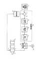
図1は、本発明の実施の形態1に係る射出成形機の温度制御装置の構成を示すブロック図である。図1に示す加熱シリンダ1は、図示しないスクリューを内蔵し、先端にはノズル2が取り付けられている。また、加熱シリンダ1の外周各部並びにノズル2の外周にはヒータ(バンドヒータ)3が巻装されており、このヒータ3を適宜通電制御することによって、加熱シリンダ1の各部並びにノズル2がそれぞれ設定された温度にコントロールされる。また、各ヒータ3を取り付けた箇所には、加熱シリンダ1の各部並びにノズル2の温度を計測するための温度検知センサー4が設けられている。なお、本例においては、説明の簡略化の為に、加熱シリンダ1の最先端のヒータ3を代表にさせて以下の説明を行う。 FIG. 1 is a block diagram showing a configuration of a temperature control device for an injection molding machine according to Embodiment 1 of the present invention. A heating cylinder 1 shown in FIG. 1 incorporates a screw (not shown), and a
図1は、上記した加熱シリンダ1の先端側のヒータ3によって温度コントロールされる部位(以下、これを端に加熱シリンダと称す)のための温度フィードバック制御系のみが示されている。温度設定値格納部6には、予め設定された成形運転時の設定温度T0のデータが書替え可能な形で格納されており、この設定温度値T0は、温度制御部14に出力される。また、温度検知センサー4により検出した信号は、温度測定部5により取り込み、実測温度Tmとして温度制御部14に出力される。温度制御部14では、加算器7により設定温度値Toと実測温度Tmとの差分を演算し、これを偏差(温度偏差)eとして、PID演算部8に出力する。 FIG. 1 shows only a temperature feedback control system for a portion whose temperature is controlled by the
PID演算部8では、入力された偏差eを用いて、公知のPID(比例・積分・微分)動作に基づくフィードバック処理を行うための演算処理を実行し、操作量uを出力する。 The
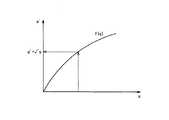
リニアリティー補正部9では、入力される操作量uを任意の関数f(u)により換算したものを、変換後の操作量u’として出力する。操作量が制御対象に加えられた時の応答が必ずしも完全直線性があるものでなく、任意の関数f(u)は、その非直線性の関係を補正するもので、理論的に計算で求めた関数や実験的に測定したデータなどから求めたものを利用する。図2は、リニアリティー補正部9による出力結果の一例を示す。 The
PWM変換部10では、変調用の搬送波(三角波)とPID演算から得られた操作量u’を指令値比較してPWM信号を得るものであるが、温度検知センサー4で検出された温度と目標温度との温度偏差が大きく、指令値が大きくなれば、PWM信号のパルス幅が大きくなり、温度偏差が小さく、上記指令値が小さくなればPWM信号のパルス幅は小さくなる。 The
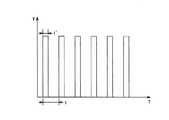
図3は、本実施の形態1におけるPWM信号の例を示すもので、tは搬送波(三角波)の周期であり、t’はPWM信号のオン時間を意味し、高速双方向スイッチ回路12のスイッチング素子をオンさせてヒータを通電させる通電時間となる。この通電時間t’は最大幅が搬送波(三角波)の周期tで、最小幅は「0」となり、0〜全時間通電まで、すなわち、ヒータヘ供給される平均電力を0から最大値までを連続して変化させることになる。 FIG. 3 shows an example of the PWM signal in the first embodiment, where t is the period of the carrier wave (triangular wave), t ′ means the on time of the PWM signal, and switching of the high-speed
また、この時の搬送波の周期tは、ヒータ用電源13で供給される交流の周期(例えば60Hzで16m秒)よりも、十分に短い時間(例えば5KHzで0.2m秒)にすることで、すなわち、ヒータ用電源13の周波数より十分に高い周波数の搬送波でPWM変調することで、ヒータ用電源13として直流ではなく交流電源を供給した場合にも、斑のない安定した電力をヒータ3に供給することができる。 In addition, the carrier wave period t at this time is sufficiently shorter (for example, 0.2 ms at 5 KHz) than the AC cycle (for example, 16 ms at 60 Hz) supplied by the
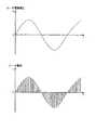
図4に、本実施の形態1におけるヒータ電流の波形を示す。ヒータ電流iは、PWM変調の搬送波の周期で、スライスしたような波形となる。PWM変調により、ヒータ電流を0〜全時間通電までを連続して可変できるが、PWM変換の指令値と、ヒータ3に供給される電力とは、直線的な比例関係にない。リニアリティー補正部9は、この非直線的な関係も補正する。ドライブ回路11は、PWM変換部10からの信号を、高速双方向スイッチ回路12を駆動するための信号に変換するための回路である。 FIG. 4 shows the waveform of the heater current in the first embodiment. The heater current i has a sliced waveform with the period of the PWM modulated carrier wave. The PWM modulation allows the heater current to be continuously varied from 0 to all the time energization, but the PWM conversion command value and the power supplied to the
図5は、高速双方向スイッチ回路12を実現する為の一実施の形態である。この例では、2個の逆阻止IGBT素子12a、12bを組み合わせて、交流信号のオン/オフができるようにした双方向のスイッチ回路である。また、逆阻止IGBT素子は、一般的なIGBTと異なり、エミッタ(E)→コレクタ(C)方向へは電流を流さない逆耐圧性能を有する素子である。また、5KHzなどの高速な周期でのオン/オフも可能な素子である。図5のA,B端子で、ヒータ3の交流電源のオン/オフを行い、G1,G2端子はドライブ回路11により駆動される制御信号を入力する。 FIG. 5 shows an embodiment for realizing the high-speed
本実施の形態1では、ヒータ用電源13として商用の交流で説明したが、交流電源を半波整流や全波整流した脈流の電源にも同様に実施することができることはいうまでもない。また、本実施の形態1では、リニアリティー補正部9を備えたが、本発明に必須である必要は無い。 In the first embodiment, the commercial power supply is described as the
以上のように、上記実施の形態によれば、特別な直流電源を用いなくても、高速なPWM信号により、ヒータヘ供給する電力を連続的に自由に制御できるので、温度制御が容易になり、オン/オフ制御による斑が無くなり、温度のオーバシュートやアンダシュートをなくし、微妙な温度制御が可能となる。また、ヒータのオン/オフの細やかな切換え制御によって射出成形機のヒータ温度を的確に制御できるようになり、成形品質が安定する。 As described above, according to the above-described embodiment, the power supplied to the heater can be continuously and freely controlled by a high-speed PWM signal without using a special DC power supply, so that temperature control becomes easy. Spots due to on / off control are eliminated, temperature overshoot and undershoot are eliminated, and subtle temperature control is possible. Further, the heater temperature of the injection molding machine can be accurately controlled by fine switching control of the heater on / off, and the molding quality is stabilized.
1 加熱シリンダ、2 ノズル部、3 ヒータ、4 温度検知センサー、5 温度測定部、6 温度設定値格納部、7 加算器、8 PID演算部、9 リニアリティー補正部、10 PWM変換部、11 ドライブ回路、12 高速双方向スイッチ回路、13 ヒータ用電源、14 温度制御部。 DESCRIPTION OF SYMBOLS 1 Heating cylinder, 2 Nozzle part, 3 Heater, 4 Temperature detection sensor, 5 Temperature measurement part, 6 Temperature setting value storage part, 7 Adder, 8 PID calculating part, 9 Linearity correction part, 10 PWM conversion part, 11 Drive circuit , 12 High-speed bidirectional switch circuit, 13 Heater power supply, 14 Temperature control unit.
Claims (2)
Translated fromJapanese前記温度制御部に、
前記PID演算部から出力される操作量をヒータ用交流電源の周波数より高い周波数の搬送波でPWM変調するPWM変換手段と、
前記PWM変換手段からの出力に基づいてヒータ用交流電源を高速に直接オン/オフさせる高速双方向スイッチ手段と
を設けたことを特徴とする射出成形機の温度制御装置。A PID calculation unit that executes a calculation process for performing a feedback process based on the PID operation using a difference between the target temperature set in the setting device and the detected temperature detected by the temperature sensor, and outputs an operation amount; In the temperature control device for an injection molding machine including a temperature control unit for controlling a heater for heating the heating cylinder of the injection molding machine based on the operation amount output from the PID calculation unit,
In the temperature control unit,
A PWM converter for PWM modulation on a carrier of a is the manipulated variable frequency havehigh Ri by the frequency of theAC power supply heater output from the PID calculation unit,
A temperature control apparatus for an injection molding machine, comprising: high-speed bidirectional switch means for directly turning on / off a heaterAC power supply at high speed based on an output from the PWM conversion means.
前記PID演算部から出力される操作量をリニアリティー補正して前記PWM変換手段に出力するリニアリティー補正手段を設けたことを特徴とする射出成形機の温度制御装置。In the temperature control apparatus of the injection molding machine according to claim 1,
A temperature control apparatus for an injection molding machine, comprising linearity correction means for linearly correcting an operation amount output from the PID calculation section and outputting the correction to the PWM conversion means.
Priority Applications (1)
| Application Number | Priority Date | Filing Date | Title |
|---|---|---|---|
| JP2005140783AJP4672430B2 (en) | 2005-05-13 | 2005-05-13 | Temperature control device for injection molding machine |
Applications Claiming Priority (1)
| Application Number | Priority Date | Filing Date | Title |
|---|---|---|---|
| JP2005140783AJP4672430B2 (en) | 2005-05-13 | 2005-05-13 | Temperature control device for injection molding machine |
Publications (2)
| Publication Number | Publication Date |
|---|---|
| JP2006315317A JP2006315317A (en) | 2006-11-24 |
| JP4672430B2true JP4672430B2 (en) | 2011-04-20 |
Family
ID=37536395
Family Applications (1)
| Application Number | Title | Priority Date | Filing Date |
|---|---|---|---|
| JP2005140783AExpired - LifetimeJP4672430B2 (en) | 2005-05-13 | 2005-05-13 | Temperature control device for injection molding machine |
Country Status (1)
| Country | Link |
|---|---|
| JP (1) | JP4672430B2 (en) |
Families Citing this family (6)
| Publication number | Priority date | Publication date | Assignee | Title |
|---|---|---|---|---|
| JP5015019B2 (en)* | 2008-01-23 | 2012-08-29 | 株式会社日本製鋼所 | Control method and control device for heater of injection molding machine |
| CN102398356B (en)* | 2011-12-06 | 2013-10-30 | 浙江大学 | Temperature control method and system for plurality of sections of barrel of injection molding machine |
| WO2016084369A1 (en)* | 2014-11-26 | 2016-06-02 | 三菱重工プラスチックテクノロジー株式会社 | Temperature control method and temperature control device |
| WO2020000150A1 (en)* | 2018-06-25 | 2020-01-02 | 深圳市丽福科技有限责任公司 | Control method and device for electronic cigarette heating temperature |
| CN108873976B (en)* | 2018-06-25 | 2020-07-07 | 深圳市丽福科技有限责任公司 | Temperature control system of electronic cigarette |
| CN108873981B (en)* | 2018-06-25 | 2020-11-10 | 深圳市丽福科技有限责任公司 | Method and device for controlling heating temperature of electronic cigarette |
Family Cites Families (3)
| Publication number | Priority date | Publication date | Assignee | Title |
|---|---|---|---|---|
| JP3568236B2 (en)* | 1994-06-08 | 2004-09-22 | ファナック株式会社 | Injection molding machine heater control device |
| JP3024696B2 (en)* | 1994-09-01 | 2000-03-21 | ファナック株式会社 | Temperature control method for injection molding machine |
| JP4188729B2 (en)* | 2003-03-13 | 2008-11-26 | 住友重機械工業株式会社 | Injection molding machine and temperature control method thereof |
- 2005
- 2005-05-13JPJP2005140783Apatent/JP4672430B2/ennot_activeExpired - Lifetime
Also Published As
| Publication number | Publication date |
|---|---|
| JP2006315317A (en) | 2006-11-24 |
Similar Documents
| Publication | Publication Date | Title |
|---|---|---|
| JP3568236B2 (en) | Injection molding machine heater control device | |
| RU2002108890A (en) | System and method for controlling the installation for electric arc welding | |
| JP4672430B2 (en) | Temperature control device for injection molding machine | |
| JP3629022B2 (en) | SPOT WELDING GUN AND METHOD OF CONTROLLING PRESSURE OF SPOT WELDING GUN | |
| CN107077104A (en) | control device | |
| KR970009961A (en) | Inverter type resistance welding control method and apparatus | |
| JP2020532056A5 (en) | ||
| JP2019168903A (en) | Temperature control circuit | |
| KR101614778B1 (en) | Zero crossing position detection module, power regulators having zero crossing position detection module, method for detecting zero point | |
| US11532998B2 (en) | Power supply circuit for measuring transient thermal resistances of semiconductor device | |
| JP5455756B2 (en) | Power converter | |
| JP4360619B2 (en) | Temperature control device, temperature control method, and program | |
| JP7109728B2 (en) | Power control device and power control method | |
| JP2009157691A (en) | Auto-tuning method, temperature controller, and heat treatment device | |
| JP4188729B2 (en) | Injection molding machine and temperature control method thereof | |
| JP3674951B2 (en) | AC power control device | |
| JP2006260047A (en) | Time proportional controller | |
| JP4188733B2 (en) | Temperature control apparatus and method for injection molding machine | |
| JP5804382B2 (en) | Temperature control circuit | |
| WO2016143114A1 (en) | Ac power regulator and output control method | |
| JP4672919B2 (en) | Laser module temperature control circuit | |
| KR0133012Y1 (en) | Motor speed controller | |
| JPH0720949A (en) | Fluid temperature controller | |
| JPH05313536A (en) | Thermal fixing device for image forming apparatus | |
| JP2015125615A (en) | Temperature control circuit |
Legal Events
| Date | Code | Title | Description |
|---|---|---|---|
| A621 | Written request for application examination | Free format text:JAPANESE INTERMEDIATE CODE: A621 Effective date:20070626 | |
| A977 | Report on retrieval | Free format text:JAPANESE INTERMEDIATE CODE: A971007 Effective date:20091111 | |
| A131 | Notification of reasons for refusal | Free format text:JAPANESE INTERMEDIATE CODE: A131 Effective date:20091117 | |
| A521 | Request for written amendment filed | Free format text:JAPANESE INTERMEDIATE CODE: A523 Effective date:20100115 | |
| TRDD | Decision of grant or rejection written | ||
| A01 | Written decision to grant a patent or to grant a registration (utility model) | Free format text:JAPANESE INTERMEDIATE CODE: A01 Effective date:20110118 | |
| A01 | Written decision to grant a patent or to grant a registration (utility model) | Free format text:JAPANESE INTERMEDIATE CODE: A01 | |
| A61 | First payment of annual fees (during grant procedure) | Free format text:JAPANESE INTERMEDIATE CODE: A61 Effective date:20110119 | |
| R150 | Certificate of patent or registration of utility model | Ref document number:4672430 Country of ref document:JP Free format text:JAPANESE INTERMEDIATE CODE: R150 Free format text:JAPANESE INTERMEDIATE CODE: R150 | |
| FPAY | Renewal fee payment (event date is renewal date of database) | Free format text:PAYMENT UNTIL: 20140128 Year of fee payment:3 | |
| R250 | Receipt of annual fees | Free format text:JAPANESE INTERMEDIATE CODE: R250 | |
| R250 | Receipt of annual fees | Free format text:JAPANESE INTERMEDIATE CODE: R250 | |
| R250 | Receipt of annual fees | Free format text:JAPANESE INTERMEDIATE CODE: R250 | |
| R250 | Receipt of annual fees | Free format text:JAPANESE INTERMEDIATE CODE: R250 | |
| R250 | Receipt of annual fees | Free format text:JAPANESE INTERMEDIATE CODE: R250 | |
| R250 | Receipt of annual fees | Free format text:JAPANESE INTERMEDIATE CODE: R250 | |
| R250 | Receipt of annual fees | Free format text:JAPANESE INTERMEDIATE CODE: R250 | |
| EXPY | Cancellation because of completion of term |