JP4671011B2 - Effect adding device, effect adding method, effect adding program, and effect adding program storage medium - Google Patents
Effect adding device, effect adding method, effect adding program, and effect adding program storage mediumDownload PDFInfo
- Publication number
- JP4671011B2 JP4671011B2JP2001230473AJP2001230473AJP4671011B2JP 4671011 B2JP4671011 B2JP 4671011B2JP 2001230473 AJP2001230473 AJP 2001230473AJP 2001230473 AJP2001230473 AJP 2001230473AJP 4671011 B2JP4671011 B2JP 4671011B2
- Authority
- JP
- Japan
- Prior art keywords
- effect
- specifying information
- array
- sequence
- determining
- Prior art date
- Legal status (The legal status is an assumption and is not a legal conclusion. Google has not performed a legal analysis and makes no representation as to the accuracy of the status listed.)
- Expired - Fee Related
Links
Images


Classifications
- G—PHYSICS
- G06—COMPUTING OR CALCULATING; COUNTING
- G06F—ELECTRIC DIGITAL DATA PROCESSING
- G06F1/00—Details not covered by groups G06F3/00 - G06F13/00 and G06F21/00
- G06F1/16—Constructional details or arrangements
- G06F1/1613—Constructional details or arrangements for portable computers
- G06F1/1615—Constructional details or arrangements for portable computers with several enclosures having relative motions, each enclosure supporting at least one I/O or computing function
- G06F1/1616—Constructional details or arrangements for portable computers with several enclosures having relative motions, each enclosure supporting at least one I/O or computing function with folding flat displays, e.g. laptop computers or notebooks having a clamshell configuration, with body parts pivoting to an open position around an axis parallel to the plane they define in closed position
- G06F1/162—Constructional details or arrangements for portable computers with several enclosures having relative motions, each enclosure supporting at least one I/O or computing function with folding flat displays, e.g. laptop computers or notebooks having a clamshell configuration, with body parts pivoting to an open position around an axis parallel to the plane they define in closed position changing, e.g. reversing, the face orientation of the screen with a two degrees of freedom mechanism, e.g. for folding into tablet PC like position or orienting towards the direction opposite to the user to show to a second user
- G—PHYSICS
- G06—COMPUTING OR CALCULATING; COUNTING
- G06F—ELECTRIC DIGITAL DATA PROCESSING
- G06F1/00—Details not covered by groups G06F3/00 - G06F13/00 and G06F21/00
- G06F1/16—Constructional details or arrangements
- G06F1/1613—Constructional details or arrangements for portable computers
- G06F1/1633—Constructional details or arrangements of portable computers not specific to the type of enclosures covered by groups G06F1/1615 - G06F1/1626
- G06F1/1662—Details related to the integrated keyboard
- G06F1/1671—Special purpose buttons or auxiliary keyboards, e.g. retractable mini keypads, keypads or buttons that remain accessible at closed laptop
- G—PHYSICS
- G06—COMPUTING OR CALCULATING; COUNTING
- G06F—ELECTRIC DIGITAL DATA PROCESSING
- G06F1/00—Details not covered by groups G06F3/00 - G06F13/00 and G06F21/00
- G06F1/16—Constructional details or arrangements
- G06F1/1613—Constructional details or arrangements for portable computers
- G06F1/1633—Constructional details or arrangements of portable computers not specific to the type of enclosures covered by groups G06F1/1615 - G06F1/1626
- G06F1/1684—Constructional details or arrangements related to integrated I/O peripherals not covered by groups G06F1/1635 - G06F1/1675
- G06F1/1686—Constructional details or arrangements related to integrated I/O peripherals not covered by groups G06F1/1635 - G06F1/1675 the I/O peripheral being an integrated camera
- H—ELECTRICITY
- H04—ELECTRIC COMMUNICATION TECHNIQUE
- H04N—PICTORIAL COMMUNICATION, e.g. TELEVISION
- H04N21/00—Selective content distribution, e.g. interactive television or video on demand [VOD]
- H04N21/20—Servers specifically adapted for the distribution of content, e.g. VOD servers; Operations thereof
- H04N21/27—Server based end-user applications
- H04N21/274—Storing end-user multimedia data in response to end-user request, e.g. network recorder
- H04N21/2743—Video hosting of uploaded data from client
- H—ELECTRICITY
- H04—ELECTRIC COMMUNICATION TECHNIQUE
- H04N—PICTORIAL COMMUNICATION, e.g. TELEVISION
- H04N21/00—Selective content distribution, e.g. interactive television or video on demand [VOD]
- H04N21/40—Client devices specifically adapted for the reception of or interaction with content, e.g. set-top-box [STB]; Operations thereof
- H04N21/41—Structure of client; Structure of client peripherals
- H04N21/422—Input-only peripherals, i.e. input devices connected to specially adapted client devices, e.g. global positioning system [GPS]
- H04N21/4223—Cameras
- H—ELECTRICITY
- H04—ELECTRIC COMMUNICATION TECHNIQUE
- H04N—PICTORIAL COMMUNICATION, e.g. TELEVISION
- H04N21/00—Selective content distribution, e.g. interactive television or video on demand [VOD]
- H04N21/40—Client devices specifically adapted for the reception of or interaction with content, e.g. set-top-box [STB]; Operations thereof
- H04N21/41—Structure of client; Structure of client peripherals
- H04N21/426—Internal components of the client ; Characteristics thereof
- H—ELECTRICITY
- H04—ELECTRIC COMMUNICATION TECHNIQUE
- H04N—PICTORIAL COMMUNICATION, e.g. TELEVISION
- H04N21/00—Selective content distribution, e.g. interactive television or video on demand [VOD]
- H04N21/40—Client devices specifically adapted for the reception of or interaction with content, e.g. set-top-box [STB]; Operations thereof
- H04N21/47—End-user applications
- H04N21/472—End-user interface for requesting content, additional data or services; End-user interface for interacting with content, e.g. for content reservation or setting reminders, for requesting event notification, for manipulating displayed content
- H04N21/47205—End-user interface for requesting content, additional data or services; End-user interface for interacting with content, e.g. for content reservation or setting reminders, for requesting event notification, for manipulating displayed content for manipulating displayed content, e.g. interacting with MPEG-4 objects, editing locally
- H—ELECTRICITY
- H04—ELECTRIC COMMUNICATION TECHNIQUE
- H04N—PICTORIAL COMMUNICATION, e.g. TELEVISION
- H04N21/00—Selective content distribution, e.g. interactive television or video on demand [VOD]
- H04N21/60—Network structure or processes for video distribution between server and client or between remote clients; Control signalling between clients, server and network components; Transmission of management data between server and client, e.g. sending from server to client commands for recording incoming content stream; Communication details between server and client
- H04N21/61—Network physical structure; Signal processing
- H04N21/6106—Network physical structure; Signal processing specially adapted to the downstream path of the transmission network
- H04N21/6125—Network physical structure; Signal processing specially adapted to the downstream path of the transmission network involving transmission via Internet
- H—ELECTRICITY
- H04—ELECTRIC COMMUNICATION TECHNIQUE
- H04N—PICTORIAL COMMUNICATION, e.g. TELEVISION
- H04N23/00—Cameras or camera modules comprising electronic image sensors; Control thereof
- H04N23/50—Constructional details
- H04N23/53—Constructional details of electronic viewfinders, e.g. rotatable or detachable
- H04N23/531—Constructional details of electronic viewfinders, e.g. rotatable or detachable being rotatable or detachable
- H—ELECTRICITY
- H04—ELECTRIC COMMUNICATION TECHNIQUE
- H04N—PICTORIAL COMMUNICATION, e.g. TELEVISION
- H04N23/00—Cameras or camera modules comprising electronic image sensors; Control thereof
- H04N23/60—Control of cameras or camera modules
- H04N23/62—Control of parameters via user interfaces
- H—ELECTRICITY
- H04—ELECTRIC COMMUNICATION TECHNIQUE
- H04N—PICTORIAL COMMUNICATION, e.g. TELEVISION
- H04N23/00—Cameras or camera modules comprising electronic image sensors; Control thereof
- H04N23/60—Control of cameras or camera modules
- H04N23/63—Control of cameras or camera modules by using electronic viewfinders
- H04N23/631—Graphical user interfaces [GUI] specially adapted for controlling image capture or setting capture parameters
- H04N23/632—Graphical user interfaces [GUI] specially adapted for controlling image capture or setting capture parameters for displaying or modifying preview images prior to image capturing, e.g. variety of image resolutions or capturing parameters
- H—ELECTRICITY
- H04—ELECTRIC COMMUNICATION TECHNIQUE
- H04N—PICTORIAL COMMUNICATION, e.g. TELEVISION
- H04N23/00—Cameras or camera modules comprising electronic image sensors; Control thereof
- H04N23/60—Control of cameras or camera modules
- H04N23/63—Control of cameras or camera modules by using electronic viewfinders
- H04N23/633—Control of cameras or camera modules by using electronic viewfinders for displaying additional information relating to control or operation of the camera
- H—ELECTRICITY
- H04—ELECTRIC COMMUNICATION TECHNIQUE
- H04N—PICTORIAL COMMUNICATION, e.g. TELEVISION
- H04N5/00—Details of television systems
- H04N5/222—Studio circuitry; Studio devices; Studio equipment
- H04N5/262—Studio circuits, e.g. for mixing, switching-over, change of character of image, other special effects ; Cameras specially adapted for the electronic generation of special effects
- H04N5/2621—Cameras specially adapted for the electronic generation of special effects during image pickup, e.g. digital cameras, camcorders, video cameras having integrated special effects capability
- H—ELECTRICITY
- H04—ELECTRIC COMMUNICATION TECHNIQUE
- H04N—PICTORIAL COMMUNICATION, e.g. TELEVISION
- H04N7/00—Television systems
- H04N7/16—Analogue secrecy systems; Analogue subscription systems
- H04N7/173—Analogue secrecy systems; Analogue subscription systems with two-way working, e.g. subscriber sending a programme selection signal
- H04N7/17309—Transmission or handling of upstream communications
- H04N7/17318—Direct or substantially direct transmission and handling of requests
Landscapes
- Engineering & Computer Science (AREA)
- Multimedia (AREA)
- Signal Processing (AREA)
- Computer Hardware Design (AREA)
- Human Computer Interaction (AREA)
- Theoretical Computer Science (AREA)
- Physics & Mathematics (AREA)
- General Engineering & Computer Science (AREA)
- General Physics & Mathematics (AREA)
- Databases & Information Systems (AREA)
- Mathematical Physics (AREA)
- User Interface Of Digital Computer (AREA)
- Studio Circuits (AREA)
- Studio Devices (AREA)
- Television Signal Processing For Recording (AREA)
- Two-Way Televisions, Distribution Of Moving Picture Or The Like (AREA)
- Display Devices Of Pinball Game Machines (AREA)
- Management Or Editing Of Information On Record Carriers (AREA)
- Processing Or Creating Images (AREA)
- Agricultural Chemicals And Associated Chemicals (AREA)
- Signal Processing For Digital Recording And Reproducing (AREA)
- Cereal-Derived Products (AREA)
Abstract
Description
Translated fromJapanese【0001】
【発明の属する技術分野】
本発明は効果付加装置、効果付加方法、効果付加プログラム及び効果付加プログラム格納媒体に関し、例えば動画に対してリアルタイムにエフェクトを付加する効果付加装置、効果付加方法、効果付加プログラム及び効果付加プログラム格納媒体に適用して好適なものである。
【0002】
【従来の技術】
従来、ビデオカメラにおいては撮影画像を編集等する際、当該撮影画像に対して文字情報(タイトル)の付加や、色調変更等のエフェクトを付加することが一般的に行われている。
【0003】
また、近年のビデオカメラにおいては、撮影時や再生時の撮影画像に対してエフェクトを付加するエフェクト付加機能を具備しており、これにより一般ユーザであっても撮影時等の撮影画像に対してエフェクトを容易に付加し得るようになされている。
【0004】
【発明が解決しようとする課題】
ところで、この種のエフェクト付加機能を有する効果(エフェクト)付加装置においては、各種エフェクトに対応して設けられた複数の操作ボタンを介して所望のエフェクトをユーザに対して選択させ得るようになされており、所望のエフェクトに対応する操作ボタンを素早く選択することは不慣れなユーザにとっては困難であるという問題があった。
【0005】
また効果付加装置においては、エフェクトの数より操作ボタンの数が少ない場合、当該操作ボタンを複数回操作して所望のエフェクトを選択しなければならず、順次異なるエフェクトを短時間で選択し得ず、撮影画像に対して順次異なるエフェクトをリアルタイムに付加することは困難であるという問題があった。
【0006】
本発明は以上の点を考慮してなされたもので、所望のエフェクトを簡易かつ迅速に選択して付加し得る効果付加装置、効果付加方法、効果付加プログラム及び効果付加プログラム格納媒体を提案しようとするものである。
【0007】
【課題を解決するための手段】
かかる課題を解決するため本発明においては、画像に対する効果を特定する効果特定情報を予め設定された配列で表示し、表示された効果特定情報の中から所望の効果特定情報を選択し、リアルタイムで入力される画像に対して付加する効果を特定する効果特定情報を選択されている効果特定情報から決定し、リアルタイムで入力される画像に対し、P決定されたタイミングで、選択された効果特定情報により特定された効果を付加し、効果が付加された画像を、リアルタイムで他の装置に送信するようにした。
【0008】
これにより、リアルタイムで入力される画像に対する効果を特定する効果特定情報を使用順の配列で表示することができ、ユーザは、所望の効果を簡易かつ迅速に選択することができ、入力画像に対して所望の効果を所望のタイミングで付加することができる。
【0009】
【発明の実施の形態】
以下、図面について、本発明の一実施の形態を詳述する。
【0010】
(1)コンテンツ配信システム
(1−1)コンテンツ配信システムの全体構成
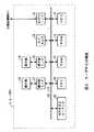
図1において、1は全体としてコンテンツ配信システムを示し、当該コンテンツ配信システム1によって後述するパーソナルキャスティングサービスを実現するようになされている。
【0011】
このコンテンツ配信システム1は、図示しないISP(Internet Service Provider)及び公衆回線網3(電話回線網3A、ケーブルテレビ網3B又はADSL(Asymmetric Digital Subscriber Line)網3C)を介してインターネット2と接続されたユーザPC(Personal Computer)4と、インターネット2に接続されたサーバ使用予約管理センタ5と、ユーザPC4から公衆回線網3又はサーバ接続専用ネットワーク6を介して受信したコンテンツをインターネット2を介して複数のクライアントPC7A、7B及び7Cへストリーム配信するストリーミングサーバ8とによって構成されている。
【0012】
この場合ユーザPC4は、ストリーミングサーバ8へコンテンツを送信する際、例えば公衆回線網3の電話回線網3Aを介してサーバ接続専用ネットワーク6のアクセスポートにPPP(Point to Point Protocol)接続を行うことにより、ストリーミングサーバ8との伝送路を確立し、当該伝送路を介してコンテンツをストリーミングサーバ8へ確実に送信し得るようになされている。
【0013】
なおユーザPC4は、公衆回線網3からISP及びインターネット2を介してストリーミングサーバ8とインターネット接続することもでき、その際には当該ユーザPC4が回線接続可能な電話回線網3A、ケーブルテレビ網3B又はADSL網3Cのうち任意に選択された伝送路を介してコンテンツをストリーミングサーバ8へ送信し得るようになされている。
【0014】
ストリーミングサーバ8は、ユーザPC4からサーバ接続専用ネットワーク6又はインターネット2を介して受信したコンテンツを、インターネット2を介して複数のクライアントPC7A、7B及び7Cへストリーム配信し得るようになされている。
【0015】
またストリーミングサーバ8は、専用回線9を介してサーバ使用予約管理センタ5とも接続されており、ユーザPC4やクライアントPC7A、7B及び7Cに対する認証処理の際に専用回線9を介して相互に認証データを授受するようになされている。
【0016】
実際上ユーザPC4は、ストリーミングサーバ8のストリーミング配信機能を使用する時間帯の予約をサーバ管理予約センタ5へ要求し、当該サーバ管理予約センタ5を介してストリーミングサーバ8に予約登録を行う。
【0017】
ストリーミングサーバ8は、ユーザPC4によって予約登録された予約時間帯になると、当該ユーザPC4から送信されたコンテンツをサーバ接続専用ネットワーク6を介して受信してバッファに記憶しながら当該コンテンツを読み出し、要求のあったクライアントPC7A、7B及び7Cへストリーム配信する。
【0018】
これによりコンテンツ配信システム1は、ユーザPC4から送信されたコンテンツを所定の予約時間帯でストリーミングサーバ8を介してクライアントPC7A、7B及び7Cへリアルタイムに提供するといった個人放送局すなわちパーソナルキャスティングサービスを実現し得るようになされている。
【0019】
なお、本実施の形態においては、ストリーミング配信機能を有するストリーミングサーバ8を用いる場合について以下説明するが、リアルタイムにコンテンツを提供し得れば、他の種々の機能を有するサーバを用いてコンテンツを提供するようにしても良い。
【0020】
(1−2)ユーザPCの構成
次に、放送者側となるユーザが撮影した例えばライブのコンテンツをストリーミングサーバ8へ送信する場合に用いられるユーザPC4の構成について説明する。
【0021】
図2に示すようにユーザPC4は、各種演算処理を実行すると共に各回路部を制御するCPU(Central Processing Unit)10、当該CPU10のワークエリアとして用いられるRAM(Random Access Memory)11、当該CPU10によって実行される一連のプログラム郡を格納したROM(Read Only Memory)12、当該CPU10によって実行されるオペレーティングシステム(例えば、「Windows95/98/2000」(マイクロソフト社))やアプリケーションプログラム等のプログラム郡を格納したハードディスク13、当該CPU10の処理結果をバス20及び表示用インターフェース15を介して受け取って表示する液晶ディスプレイ等でなる表示部14、ユーザが命令を入力するためのキーボード、マウス、後述する回転、回動及び押圧自在なジョグダイヤル等の操作ボタンでなる操作部16、当該操作部16で入力された命令をバス20を介してCPU10へ送出する操作部インターフェース17、公衆回線網3を介してインターネット2(図1)やサーバ接続専用ネットワーク6と接続された外部装置との間でデータを授受するためのネットワークインターフェース18、ユーザPC4と一体に取り付けられたディジタルビデオカメラ19及びコンテンツをMPEG(Moving Picture Experts Group)2規格に従って圧縮符号化するMPEG2コーデック22を備えた構成を有する。なおハードディスク13は、CPU10によって読み書きされ、コンテンツ及び各種制御用データの保管用にも使用される。
【0022】
ここでユーザPC4は、図3(A)に示すように液晶ディスプレイでなる表示部14が設けられた表示側筐体部31Aと、キーボード16Aが設けられたキーボード側筐体部31Bとを有し、ヒンジ部32を介して相互に回動可能な状態に連結されている。
【0023】
表示側筐体部31Aは、キーボード側筐体部31Bに対して矢印a方向に回動自在に取り付けられており、図3(B)に示すように当該表示側筐体部31Aが180度回転された状態で使用し得ると共に、当該表示側筐体部31Aの右端部上方に回転、回動及び押圧自在なジョグダイヤル16Bが取り付けられている。
【0024】
キーボード側筐体部31Bは、当該キーボード側筐体部31Bの右側端面に対して、複数(4種類)の操作ボタン16Cが配設された操作ボタン筐体部31Cが取付固定されていると共に、ディジタルビデオカメラ19が当該右側端面の一点で指示されており、これにより矢印b方向へ自在に回動し得るようになされている。
【0025】
なおユーザPC4は、図4(A)に示すような形態で使用することができ、この場合にはユーザが当該ユーザPC4を把持し、当該ユーザ自身をディジタルビデオカメラ19によって撮影することが可能となる。この際、ユーザは表示部14が当該ユーザに向けられていることにより、撮影内容を表示部14を介して目視確認しながら撮影することができる。
【0026】
しかしながら、このような形態で使用する場合、キーボード16Aが表示部14の裏側に位置するため、ユーザはキーボード16Aを用いて正確に操作することは困難である。
【0027】
この点を考慮してユーザPC4は、ディジタルビデオカメラ19による撮影や当該撮影に関する命令(例えば、撮影開始、停止、ズーム、エフェクトの付加、コンテンツの保存、送信等の命令)を、ジョグダイヤル16B及び操作ボタン16Cを適宜操作することによって入力し得るようになされている。
【0028】
またユーザPC4は、図4(B)に示すような形態で使用することができ、この場合にはユーザに対して当該ユーザPC4を把持させ、正面の撮影対象を表示部14でユーザに目視確認させながらディジタルビデオカメラ19によって撮影することができる。
【0029】
実際上ユーザPC4(図2)は、電源の投入に応じてCPU10がROM12及びハードディスク13に格納されている各種アプリケーションプログラム郡を読み出して実行することにより、撮影処理、特殊効果を施す等のコンテンツに対する加工処理、ストリーミングサーバ8への当該コンテンツの送信処理及びWWW(World Wide Web)ブラウジング等の各種処理を実行する。
【0030】
(1−3)ユーザPCの機能
以下、ユーザPC4のCPU10が上述の各種アプリケーションプログラム郡に従って所定の処理を実行することにより実現される様々な機能について具体的に説明する。まず、ユーザPC4においては、CPU10の制御により図5に示すような初期画面35を表示部14に表示する。
【0031】
この初期画面35には、ディジタルビデオカメラ19により撮影された画像を表示する大型サイズの主画像表示エリア40と、前回の撮影時において最後に撮影された画像のプレビューを表示する小型サイズの副画像表示エリア41とが設けられ、当該副画像表示エリア41の下部にモード(mode)、画像種類(camera)、設定(setting)及び命令内容(operation)といった上位項目をユーザに選択させるためのGUI(Graphical User Interface)42が設けられると共に、主画像表示エリア40の下部にユーザPC4の各種状態を示すステータスウィンドウ43が設けられている。
【0032】
GUI42の上位項目「mode」には、撮影モード(「撮る」が選択された場合のモード)、アップロードモード(「見る・送る」が選択された場合のモード)、Web確認モード(「Webを見る」が選択された場合のモード)、ライブ予約/確認モード(「ライブ予約/確認へ」が選択された場合のモード)及びライブ配信モード(「ライブ配信へ」が選択された場合のモード)からなる5種類のモードが選択対象として表示されている。因みに、ユーザPC4の起動時には初期状態として撮影モードが選択されている。
【0033】
ここで撮影モードは、ユーザPC4のディジタルビデオカメラ19により撮影を行うためのモードであり、当該撮影モードが選択された場合若しくは初期状態において、CPU10は図6(A)に示すような撮影モード画面50を表示部14に表示する。
【0034】
この撮影モード画面50では、上述した初期画面35(図5)と同様に主画像表示エリア60及び副画像表示エリア61が設けられており、主画像表示エリア60に現在撮影中の画像が表示されると共に、副画像表示エリア61に前回撮影したときの最後の画像がプレビュー表示される。
【0035】
また撮影モード画面50では、初期画面35と同様のGUI62が設けられ、図6(B)に示すように当該GUI62にも「mode」、「camera」、「setting」及び「operation」といった上位項目が設けられている。
【0036】
これらの上位項目には、さらに複数の下位項目がそれぞれ設けられており、表示側筐体部31Aにおけるジョグダイヤル16Bの回転操作に応じて太線枠で示されたフォーカスFが所望の下位項目へ移動された後に当該ジョグダイヤル16Bが押圧操作されることにより、その下位項目が選択決定されるようになされている。
【0037】
また撮影モードでは、操作ボタン筐体部31Cに設けられた操作ボタン16C(図3及び図4)に対しても、所定のコマンド(例えば、撮影時の画像に特殊効果を施すためのエフェクト項目を選択決定するコマンド等)が予め割り当てられている。
【0038】
従ってユーザは、キーボード16Aを用いることなく、ジョグダイヤル16B又は操作ボタン16Cに対する操作だけで撮影モードにおける各種操作を実行し得、図4(A)及び(B)に示した場合のようなキーボード16Aが操作し難い環境下であっても容易に撮影操作を実行し得るようになされている。
【0039】
なお撮影モードにおいては、デフォルトとして操作ボタン16Cに対して撮影時の画像に特殊効果を施すためのエフェクト項目を選択決定するコマンドが予め割り当てられているが、操作ボタン16Cに対して任意にコマンドを割り当てたり、又は他のモードにおいて操作ボタン16Cに他の種々のコマンドを割り当てるようにしても良い。この場合ユーザPC4の操作性は、一段と向上することになる。
【0040】
さらに撮影モードでは、ステータスウィンドウ63に現時点におけるユーザPC4の状態(例えば、バッテリ残量やハードディスク13の残記憶容量等)、選択中のモードにおける処理状態(例えば撮影中の画像データサイズ、画像データの指定保存先及び操作ボタン16Cに対して割り当てられているコマンドの種類等)が表示される。
【0041】
ところで撮影モードでは、画像データの保存先としてハードディスク13に代えてネットワーク上のサーバを指定し得るようになされており、その場合にはコンテンツ配信システム1におけるストリーミングサーバ8を保存先として指定し、フォーカスFによる「キャプチャ」ボタンの選択操作に応じて画像データがインターネット2を介してストリーミングサーバ8へ転送される。
【0042】
実際上、図7に示すようにユーザPC4のCPU10は、ルーチンRT1の開始ステップから入って次のステップSP1に移る。ステップSP1においてユーザPC4のCPU10は、撮影モード時に撮影したコンテンツの画像データの保存先としてストリーミングサーバ8が指定されている場合、フォーカスFにより「キャプチャ」ボタンが選択されたか否かを判定する。
【0043】
ここで否定結果が得られると、このことは「キャプチャ」ボタンが選択操作されていないことを表しており、このときユーザPC4のCPU10は「キャプチャ」ボタンが選択操作されるまで待ち受ける。
【0044】
これに対してステップSP1で肯定結果が得られると、このことは「キャプチャ」ボタンが選択操作されたことを表しており、このときユーザPC4のCPU10は次のステップSP2へ移る。
【0045】
ステップSP2においてユーザPC4のCPU10は、「キャプチャ」ボタンが選択操作された時点における撮影画像の画像データを取り込んでハードディスク13に一旦記憶し、次のステップSP3へ移る。
【0046】
ステップSP3においてユーザPC4のCPU10は、当該ユーザPC4がインターネット2と接続されているか否かを判定する。ここで否定結果が得られると、このことは未だインターネット2とは接続されていないことを表しており、このときユーザPC4のCPU10は次のステップSP5へ移り、インターネット2への接続処理を行い、次のステップSP4へ移る。
【0047】
これに対してステップSP3で肯定結果が得られると、このことは既にインターネット2とは接続されていることを表しており、このときユーザPC4のCPU10は次のステップSP4へ移る。
【0048】
ステップSP4においてユーザPC4のCPU10は、予め登録されているうRL(Uniform Resource Locator)に基づいてストリーミングサーバ8への接続処理を開始し、次のステップSP6へ移る。
【0049】
ステップSP6においてユーザPC4のCPU10は、サーバ使用予約管理センタ5に対して予め保持しているユーザ登録情報を送信し、当該サーバ使用予約管理センタ5によってユーザ登録確認が行われ、正規ユーザであることが判断された場合、ハードディスク13に格納した画像データをストリーミングサーバ8へ転送し、次のステップSP7へ移る。
【0050】
ステップSP7及びステップSP8においてユーザPC4のCPU10は、インターネット2との接続が切断されるか保存先が変更されるまでは、「キャプチャ」ボタンが選択操作されたことに応じて撮影画像の画像データを取り込み、ストリーミングサーバ8へ転送を行う。
【0051】
このようにユーザPC4のCPU10は、ストリーミングサーバ8との接続処理や画像データの転送処理を自動的に行うことにより、ユーザに対して特別な操作を行わせることなくストリーミングサーバ8のメモリにコンテンツの画像データを保存し得るようになされている。
【0052】
次にアップロードモードは、上述した撮影モードで撮影したコンテンツを表示部14を介してユーザに参照させたり、当該コンテンツの画像データをインターネット2と接続された所定のアップロード先のストリーミングサーバ8へ送信するためのモードであり、CPU10は図8(A)に示すようなアップロードモード画面51を表示部14に表示する。
【0053】
このアップロードモード画面51では、撮影モード画面50(図6)と同様のGUI72及びステータスウィンドウ73が設けられると共に、新にプレビューエリア74、撮影したコンテンツのうち代表的な静止画像を複数並べて表示する一覧表示エリア75及び送信カプセルアイコン77が設けられている。
【0054】
図8(B)に示すように、アップロードモード画面51におけるGUI72には、「mode」項目の他に「operation」項目及び「view」項目が設けられている。
【0055】
「operation」項目には、インターネット2との接続/切断を命令するための「ネット接続/切断」ボタン、コンテンツの送信開始/終了を命令するための「送信開始/終了」ボタンが下位項目として設けられ、また「view」項目には、一覧表示エリア75へフォーカスFの移動を命令するための「フォーカス移動」ボタン、送信カプセルアイコン77の中身を確認する、すなわち送信すべく選択したコンテンツの一覧をユーザが参照するための「送信カプセル参照」ボタンが下位項目として設けられている。
【0056】
このGUI72においても、撮影モード画面50(図6)の場合と同様に、表示側筐体部31Aにおけるジョグダイヤル16Bの回転操作に応じてフォーカスFが所望の下位項目へ移動された後に当該ジョグダイヤル16Bが押圧操作されることにより当該下位項目が選択決定されるようになされている。
【0057】
またアップロードモードにおいては、操作ボタン16C(図3及び図4)に対して、プレビューエリア74に表示したコンテンツの再生/停止や、静止画像の表示を命令するコマンドが予め割り当てられており、ステータスウィンドウ73には画像データのファイル名、ファイルサイズ、フォーマット(JPEG(Joint Photographic Experts Group)又はMPEG等)や、現在指定されている送信先を示す情報(アップロード先のサーバ名及びそのURL)等が表示される。
【0058】
ここでCPU10は、ユーザによるジョグダイヤル16Bの回転操作に応じてフォーカスFを「フォーカス移動」ボタンに移動した後、当該ジョグダイヤル16Bの押圧操作に応じて当該「フォーカス移動」ボタンが決定されたことを認識すると、フォーカスFを一覧表示エリア75上へ移動する。
【0059】
ユーザは、フォーカスFが一覧表示エリア75上に移動された状態でジョグダイヤル16Bを回転操作することにより、当該フォーカスFを当該一覧表示エリア75の静止画像上で移動させることができる。続いてユーザは、所望の静止画像上にフォーカスFを移動させた状態でジョグダイヤル16Bを押圧操作することにより、当該所望の静止画像を容易に選択して送信すべきコンテンツを決定し得るようになされている。
【0060】
このときCPU10は、サブGUI76を一覧表示エリア75の隣に表示し、図8(C)に示すように当該サブGUI76の各項目上にフォーカスFを移動して表示する。
【0061】
サブGUI76には、「保存」ボタン、「削除」ボタン、「プレビュー」ボタン及び「送信カプセルに入れる」ボタンといった選択ボタンが設けられており、ジョグダイヤル16Bの回転操作及び押圧操作によりフォーカスFで「送信カプセルに入れる」ボタンが選択決定されると、CPU10は一覧表示エリア75の中から選択決定されたコンテンツを送信カプセルアイコン77の送信すべきコンテンツの一覧に加えるようになされている。
【0062】
その後ユーザによってフォーカスFがGUI72に戻され、当該フォーカスFで「送信開始/終了」ボタンが選択決定されると、CPU10は先ほど送信カプセルアイコン77に加えたものを含む全てのコンテンツを所定のアップロード先のストリーミングサーバ8へ送信するようになされている。
【0063】
次にWeb確認モードは、インターネット2と接続してブラウジングを行うモードであり、Web確認モードが選択されると、CPU10は図9(A)に示すようなWeb確認モード画面52を表示部14に表示する。
【0064】
このWeb確認モード画面52では、撮影モード画面50(図6)と同様のGUI82及びステータスウィンドウ83が設けられていると共に、新にWebブラウザを表示するためのブラウザ表示エリア80と、当該ブラウザ表示エリア80に表示したリソースのURLを表示するURL表示欄84とが設けられている。
【0065】
ここでWeb確認モードが選択された場合、CPU10はハードディスク13からブラウザソフトウェア(例えば、Internet Explorer(マイクロソフト社)又はNetscape Navigator(ネットスケープ社))を読み出して実行することにより、ブラウザ表示エリア80にブラウザソフトウェアによるブラウジング画像を表示する。
【0066】
また、図9(B)に示すようにWeb確認モード画面52のGUI82には、初期画面35における「setting」項目及び「camera」項目に代えて新に「browsing」項目が設けられている。
【0067】
この「browsing」項目には、所定のWebページにジャンプすることを命令するための「予約ジャンプ」ボタン、ブラウザを操作するための「次へ」ボタン及び「戻る」ボタン等の下位項目が設けられている。なお、このWeb確認モードでは、URLを入力してブラウジングを行うといった通常の一般的なブラウジング処理を実行することも可能である。
【0068】
このGUI82においても、撮影モード画面50の場合と同様に、表示側筐体部31Aにおけるジョグダイヤル16Bの回転操作に応じてフォーカスFが所望の下位項目へ移動された後に当該ジョグダイヤル16Bが押圧操作されることにより当該下位項目が選択決定されるようになされている
【0069】
次にライブ予約/確認モードは、ストリーミングサーバ8のストリーム配信機能により生中継でコンテンツの個人放送を行うための時間帯を予約するモードであり、ライブ予約/確認モードが選択されると、CPU10は図10(A)に示すようなライブ予約/確認モード画面53を表示部14に表示する。
【0070】
このライブ予約/確認モード画面53では、Web確認モード画面52(図9)と同様のブラウザ表示エリア90、GUI92、ステータスウィンドウ93及びURL表示欄94が設けられていると共に、新に予約一覧表示エリア95が設けられている。
【0071】
また図10(B)に示すようにライブ予約/確認モード画面53のGUI92には、Web確認モード画面52(図9)のGUI82と同様に「mode」項目、「operation」項目及び「browsing」項目が設けられており、当該「browsing」項目には、ライブ予約を行うためのWebページにジャンプすることを命令する「予約ジャンプ」ボタンや、ブラウザを操作するための「次へ」ボタン及び「戻る」ボタン等が設けられている。
【0072】
またGUI92においても、Web確認モード画面52の場合と同様に、表示側筐体部31Aにおけるジョグダイヤル16Bの回転操作に応じてフォーカスFが所望の下位項目へ移動された後に当該ジョグダイヤル16Bが押圧操作されることにより当該下位項目が選択決定されるようになされている
【0073】
なお、ライブ予約を行うためのWebページとは、サーバ使用予約管理センタ5内の後述するライブキャスティングサーバがそのハードディスクに格納しているライブ予約のための予約用画面のWebページである。
【0074】
ここでユーザPC4のCPU10は、ユーザにより「予約ジャンプ」ボタンがフォーカスFで選択決定されると、サーバ使用予約管理センタ5内のライブキャスティングサーバへアクセスし、当該ライブキャスティングサーバへ予約要求情報を送信したり、ライブキャスティングサーバからライブ予約設定情報ファイルをダウンロードする等のライブ予約に関する各種データを授受し得るようになされている。
【0075】
ライブ予約/確認モード画面53における予約一覧表示エリア95には、サーバ使用予約管理センタ5に対して行われたライブ予約の予約項目が一覧表示され、当該予約項目毎に設定された時間帯等の概要情報が表示されている。
【0076】
ユーザPC4のCPU10は、ユーザのジョグダイヤル16Bに対する回転操作及び押圧操作によりフォーカスFを介して予約一覧表示エリア95の任意の予約項目が選択決定されると、サーバ使用予約管理センタ5内のライブキャスティングサーバに対して当該予約項目の予約内容を示す予約確認用画面のWebページへジャンプする制御を行う。この場合のユーザPC4のCPU10とサーバ使用予約管理センタ5との間のライブ予約に関する処理については後述する。
【0077】
次に、ライブ配信モードは、ユーザPC4のディジタルビデオカメラ19によって撮影したコンテンツをストリーミングサーバ8のストリーム配信機能によりあたかも個人放送局のようにインターネット2を経由してクライアントPC7A、7B及び7Cへリアルタイムに配信するためのモードである。
【0078】
実際上ユーザPC4のCPU10は、ユーザによってライブ配信モードが選択されると、図11(A)に示すようなライブ配信モード画面54を表示部14に表示する。
【0079】
このライブ配信モード画面54では、GUI102、ライブ配信を行う際のコンテンツの動画像データに対して施すべき各種エフェクトが設定されたエフェクトリスト表示欄105、それらの各種エフェクトによる特殊効果が施されたエフェクト画像を表示するプレビュー画像表示エリア104及び実際に特殊効果を施しているエフェクトの種類を示すカレントエフェクト表示エリア106が設けられている。因みに、当該プレビュー画像表示エリア104に表示されたエフェクト画像が実際にストリーミングサーバ8へ送信されるべきコンテンツの画像となる。
【0080】
GUI102には、ライブ配信モードに切り換えるための「ライブ配信」ボタン及びライブ予約/確認モードに切り換えるための「ライブ予約確認」ボタンが設けられていると共に、エフェクトリスト表示欄105へフォーカスFを移動するための「エフェクトリスト」ボタン、コンテンツの動画像データに対して施す各種エフェクトを設定するための「エフェクト設定」ボタンが設けられている。
【0081】
さらにGUI102には、インターネット2と接続/切断することを命令するための「ネット接続/切断」ボタン、ライブ配信の開始/終了を命令するための「配信開始/終了」ボタン及びライブ配信の一時停止を命令するための「一時停止」ボタンが設けられている。
【0082】
プレビュー画像表示エリア104には、プレビュー表示画面104Aの下部に、ライブコンテンツのタイトル、ライブ配信中であることを「ONAIR」の文字で示すオンエアー情報、パーソナルキャスティングサービスにおけるサービス提供者側の時刻情報、ライブ配信に関する配信開始時刻や終了予定時刻を示す予約時間帯情報、画像サイズ情報、配信データの伝送速度(ビットレート)を示すビットレート情報等が表示される。
【0083】
またエフェクトリスト表示欄105には、操作ボタン16C(図3及び図4)のいずれか一つをAボタン、当該操作ボタン16Cの他のいずれか一つをBボタンとした場合に、Aボタンが押下されている間だけ特殊効果を施す一発系エフェクトが設定されている一発系エフェクト表示欄105Aと、継続的に特殊効果を施す継続系エフェクトが設定されている継続系エフェクト表示欄105Bとが左右両側に分かれて縦一列づつ設けられている。
【0084】
ここで、ユーザがエフェクトリスト表示欄105の一発系エフェクト表示欄105A及び継続系エフェクト表示欄105Bに一発系エフェクト及び継続系エフェクトを設定する場合には、GUI102の「エフェクト設定」ボタンを選べば良い。
【0085】
すなわちユーザPC4のCPU10は、「エフェクト設定」ボタンがクリックされると、アプリケーションプログラムに基づいて、図12に示すようなエフェクト設定画面110をライブ配信モード画面54に重ねて表示する。
【0086】
このエフェクト設定画面110は、エフェクトリスト表示欄105の一発系エフェクト表示欄105Aに表示される一発系エフェクトの種類及びその順番を設定するための一発系エフェクト設定画面110Aと、継続系エフェクト表示欄105Bに表示される継続系エフェクトの種類及びその順番を設定するための継続系エフェクト設定画面110Bと、配信中に継続系エフェクトの特殊効果を終始施すように設定するためのプリセットエフェクト設定画面110Cとが切り換えられるようになされている。
【0087】
エフェクト設定画面110の一発系エフェクト設定画面110Aに切り換えられた状態では、一発系エフェクトリスト欄111に選択対象となる複数の一発系エフェクトが表示されており、ユーザは所望の一発系エフェクトを選択して一発系エフェクト設定欄112へドラッグアンドドロップすることにより、一発系エフェクトの種類及びその順番(上から順番が決定される)を設定するようになされている。
【0088】
因みに一発系エフェクト設定画面110Aでは、一発系エフェクトリスト欄111だけがアクティブであり、継続系エフェクト設定欄113及びプリセットエフェクト設定欄114には網掛処理が施されており、一発系エフェクトが継続系エフェクト設定欄113又はプリセットエフェクト設定欄114に設定されることを防止している。
【0089】
次に、エフェクト設定画面110の継続系エフェクト設定画面110Bに切り換えられた状態では、継続系エフェクトリスト欄115に選択対象となる複数の継続系エフェクトが表示されており、ユーザは所望の継続系エフェクトを選択して継続系エフェクト設定欄113へドラッグアンドドロップすることにより、継続系エフェクトの種類及びその順番を設定するようになされている。
【0090】
なお、この継続系エフェクト設定画面110Bでも、継続系エフェクトリスト欄113だけがアクティブであり、一発系エフェクト設定欄112及びプリセットエフェクト設定欄114には網掛処理が施されており、継続系エフェクトが一発系エフェクト設定欄112又はプリセットエフェクト設定欄114に設定されることを防止している。
【0091】
続いて、エフェクト設定画面110のプリセットエフェクト設定画面110Cに切り換えられた状態では、継続系エフェクトリスト欄115に選択対象となる複数の継続系エフェクトが表示されており、ユーザは所望の継続系エフェクトを選択してプリセットエフェクト設定欄114へドラッグアンドドロップすることにより、プリセットエフェクトを設定するようになされている。因みに、プリセットエフェクト設定欄114には1種類のプリセットエフェクト(例えば「日時」を表示するエフェクト)だけが設定される。
【0092】
なお、このプリセットエフェクト設定画面110Cでも、プリセットエフェクト設定欄114だけがアクティブであり、一発系エフェクト設定欄112及び継続系エフェクト設定欄113には網掛処理が施されており、一発系エフェクト設定欄112又は継続系エフェクト設定欄113に継続系エフェクトがプリセットエフェクトとして設定されることを防止している。
【0093】
このようにしてエフェクト設定画面110において、一発系エフェクト、継続系エフェクト及びプリセットエフェクトが設定されると、ライブ配信モード画面54(図11)におけるエフェクトリスト表示欄105の一発系エフェクト表示欄105A及び継続系エフェクト表示欄105Bに一発系エフェクト及び継続系エフェクトが順番通り表示されることになる。
【0094】
この場合、一発系エフェクト表示欄105A及び継続系エフェクト表示欄105Bに表示される一発系エフェクト及び継続系エフェクトは、コンテンツを撮影する際のシナリオ等に沿ってその順番が設定されることが望ましく、当該一発系エフェクト表示欄105A及び継続系エフェクト表示欄105Bにはその順番通りに一発系エフェクト及び継続系エフェクトが表示されている。
【0095】
このようにしてライブ配信モード画面54におけるエフェクトリスト表示欄105の一発系エフェクト表示欄105A及び継続系エフェクト表示欄105Bに設定された一発系エフェクト及び継続系エフェクトの種類及び順番については、ハードディスク13に格納されて記憶される。
【0096】
因みに、このライブ配信モード画面54(図11)におけるエフェクトリスト表示欄105は、一発系エフェクト設定欄105A及び継続系エフェクト設定欄105Bに一発系エフェクト及び継続系エフェクトが既に設定されている状態であり、ジョグダイヤル16Bの回転操作に応じて相互に隣接した一発系エフェクト及び継続系エフェクトが組み合わされた状態で同時に回転移動するようになされている。
【0097】
但し、このときフォーカスFは図示の位置で固定されており、隣同士が1対となった一発系エフェクト及び継続系エフェクトがジョグダイヤル16Bの回転操作に応じてフォーカスFの背後で同時に回転移動することになる。
【0098】
このようにジョグダイヤル16Bの回転操作に応じて特殊効果を与えるべきエフェクトがフォーカスFによって選択され、当該フォーカスFにより選択された状態で操作ボタン16CのうちのAボタン若しくはBボタンが押下されると、ユーザPC4のCPU10は押下されたAボタン若しくはBボタンに対応した特殊効果をそのときの画像データに対して施すようになされている。
【0099】
すなわちユーザPC4のCPU10は、相互に隣接して組み合わされた一発系エフェクト及び継続系エフェクトをその状態で同時に回転移動することにより、その組み合わせのまま一発系エフェクト及び継続系エフェクトの特殊効果を画像データに対して施す場合には、ジョグダイヤル16Bを回転操作しないで済む分だけ短時間でエフェクトを選択し得るようになされている。
【0100】
ライブ配信モード画面54(図11)のカレントエフェクトリスト表示エリア106には、フォーカスFで選択されてAボタンの押下された一発系エフェクト、フォーカスFで選択されてBボタンの押下された継続系エフェクト及びプリセットエフェクト設定欄114に設定されたプリセットエフェクトが表示されるようになされており、現時点で選択されているエフェクトの種類をユーザに対して認識させ得るようになされている。
【0101】
またライブ配信モード画面54においては、フォーカスFによって選択された隣同士の1対となった一発系エフェクト及び継続系エフェクトに関する特殊効果を施すばかりではなく、隣同士ではない一発系エフェクトと継続系エフェクトとを組み合わせて特殊効果を施すこともできるようになされている。
【0102】
ユーザPC4のCPU10は、例えばフォーカスFで「フラワー」の一発系エフェクト及び「セピア」の継続系エフェクトを選択した状態でBボタンが押下されたことに対応して「セピア」の継続系エフェクトを施し、その上で、ジョグダイヤル16Bの回転操作によりフォーカスFで「ハート」の一発系エフェクト及び「モザイク」の継続系エフェクトを選択し、その状態でAボタンが押下されたことに対応して「ハート」の一発系エフェクトを施し得るようにもなされている。
【0103】
従って、この場合「ハート」の一発系エフェクト及び「セピア」の継続系エフェクトが施されている状態となり、隣同士で1対となった組み合わせ以外の一発系エフェクト及び継続系エフェクトを施すことが可能となる。
【0104】
但し、ライブ配信モード画面54としては、最終的にはフォーカスFが「ハート」の一発系エフェクト及び「モザイク」の継続系エフェクトを選択した状態となり、あたかもフォーカスFで選択されている「ハート」の一発系エフェクト及び「モザイク」の継続系エフェクトが特殊効果として施されているかのような誤解をユーザに対して与えてしまうことにもなる。
【0105】
そこでユーザPC4のCPU10は、フォーカスFで選択した一発系エフェクト及び継続系エフェクトの表示とは無関係に、実際に画像データに対して施している特殊効果の種類を示す一発系エフェクト及び継続系エフェクトをカレントエフェクト表示エリア106に表示することにより、上述のような誤解が生じることを防止し得るようになされている。
【0106】
なお、カレントエフェクト表示エリア106には、Aボタンに対応した一発系エフェクト、Bボタンに対応した継続形エフェクトだけではなく、配信中継続して特殊効果が施されるべきプリセットエフェクトについても常時表示すると共に、左側から「Aボタンに対応した一発系エフェクト+Bボタンに対応した継続形エフェクト+プリセットエフェクト」として表示することにより、特殊効果を画像データに施すべき順番についても直感的に認識させ得るようになされている。
【0107】
ここで、ジョグダイヤル16Bの回転操作及び押圧操作によりフォーカスFを介して「配信開始/終了」ボタンが選択決定されると、ユーザPC4のCPU10は上述したライブ予約/確認モードにおいてサーバ使用予約管理センタ5内のライブキャスティングサーバから供給されたライブ配信用の予約設定情報ファイルに従い、サーバ接続専用ネットワーク6を介する専用回線接続又はインターネット2を介するインターネット接続によりストリーミングサーバ8と伝送路を確立する。
【0108】
続いてユーザPC4のCPU10は、予約設定情報ファイルに設定された内容(例えば、データ伝送速度等)に従って、ディジタルビデオカメラ19で撮影したコンテンツの動画像データをリアルタイムにストリーミングサーバ8へ送信するようになされている。
【0109】
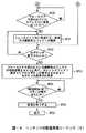
実際上、ユーザPC4のCPU10はコンテンツの動画像データに対して所望の特殊効果を施してストリーミングサーバ8へ送信する場合、図13及び図14に示すコンテンツの配信処理シーケンスに従って行う。
【0110】
すなわちユーザPC4のCPU10は、ルーチンRT2の開始ステップから入って次のステップSP11へ移る。ステップSP11においてユーザPC4のCPU10は、ライブ配信モード画面54(図11)で「エフェクト設定」ボタンが選択されたことに応じてエフェクト設定画面110(図12)を表示し、次のステップSP12へ移る。
【0111】
ステップSP12においてユーザPC4のCPU10は、ユーザのエフェクト設定画面110に対する操作に従って一発系エフェクト、継続系エフェクト及びプリセットエフェクトの設定を行い、次のステップSP13へ移る。
【0112】
ステップSP13においてユーザPC4のCPU10は、各種エフェクトの設定が終了したか否かを判定する。ここで否定結果が得られると、このことは各種エフェクトの設定が未だ終了していないことを表しており、このときユーザPC4のCPU10はステップ12に戻って各種エフェクトの設定を続ける。
【0113】
これに対してステップSP13で肯定結果が得られると、このことは各種エフェクトの設定が終了したことを表しており、このときユーザPC4のCPU10は、次のステップSP14へ移る。
【0114】
ステップSP14においてユーザPC4のCPU10は、各種エフェクトの設定が終了したのでエフェクト設定画面110からライブ配信モード画面54へ戻し、その時点でフォーカスFにより囲われている一発系エフェクト及び継続系エフェクトと、設定されたプリセットエフェクトのサンプル画像をカレントエフェクト表示エリア106に表示することにより、現在フォーカスFで選択されているエフェクトの種類をユーザに対して認識させ、次のステップSP15へ移る。
【0115】
ステップSP15においてユーザPC4のCPU10は、予めライブ予約/確認モードにおいて予約されたライブ配信の予約時間帯に合わせて、「配信開始/終了」ボタンが操作されたか否かを判定する。
【0116】
ここで否定結果が得られると、このことは未だ「配信開始/終了」ボタンが操作されていないことを表しており、このときユーザPC4のCPU10は「配信開始/終了」ボタンが操作されるまで待ち受ける。
【0117】
これに対してステップSP15で肯定結果が得られると、このことはライブ配信を行うべき配信開始時刻に合わせて「配信開始/終了」ボタンが操作されたことを表しており、このときユーザPC4のCPU10は次のステップSP16へ移る。
【0118】
ステップSP16においてユーザPC4のCPU10は、「配信開始/終了」ボタンが操作されたことに応じて、撮影中のコンテンツの画像データ及び音声データを公衆回線網3又はサーバ接続専用ネットワーク6を介してストリーミングサーバ8へ送信することにより、当該ストリーミングサーバ8を介してコンテンツのライブ配信を開始し、次のステップSP17へ移る。
【0119】
ステップSP17においてユーザPC4のCPU10は、ジョグダイヤル16Bの回転操作によりエフェクトリスト表示欄105のフォーカスFを介してユーザが希望する一発系エフェクト又は継続系エフェクトを選択し、次のステップSP18へ移る。
【0120】
ステップSP18においてユーザPC4のCPU10は、フォーカスFにより一発系エフェクト又は継続系エフェクトを選択した状態で、操作ボタン16CのAボタンが押下されたか否かを判断する。ここで否定結果が得られると、このことはAボタンが押下されていないことを表しており、このときユーザPC4のCPU10は次のステップSP21へ移る。
【0121】
これに対してステップSP18で肯定結果が得られると、このことはAボタンの押下によってフォーカスFにより囲われている一発系エフェクトの特殊効果を与える命令が入力されたことを表しており、このときユーザPC4のCPU10は次のステップSP19へ移る。
【0122】
ステップSP19においてユーザPC4のCPU10は、フォーカスFで囲われている一発系エフェクトの特殊効果を画像データに対してリアルタイムに施し得ると共に、カレントエフェクト表示エリア106のAボタン対応部分に現在特殊効果を施している一発系エフェクトの種類を示すサンプル画像を表示し、次のステップSP20へ移る。
【0123】
ステップSP20においてユーザPC4のCPU10は、ジョグダイヤル16Bの回転操作によりフォーカスFで囲われていた一発系エフェクト及び継続系エフェクトに変更があったか否かを判定する。
【0124】
ここで否定結果が得られると、このことはフォーカスFで囲われている一発系エフェクト及び継続系エフェクトに変更はないことを表しており、このときユーザPC4のCPU10は再度ステップSP20に戻り、フォーカスFで囲われている一発系エフェクト及び継続系エフェクトに変更があるまで待ち受ける。
【0125】
これに対してステップSP20で肯定結果が得られると、このことはフォーカスFで囲われている一発系エフェクト及び継続系エフェクトに変更があったことを表しており、このときユーザPC4のCPU10は次のステップSP21へ移る。
【0126】
ステップSP21においてユーザPC4のCPU10は、ユーザの操作により、フォーカスFで次に希望する一発系エフェクト又は継続系エフェクトの選択を行い、次のステップSP22へ移る。
【0127】
ステップSP22においてユーザPC4のCPU10は、フォーカスFにより次の一発系エフェクト又は継続系エフェクトを選択した状態で、操作ボタン16CのBボタンが押下されたか否かを判断する。ここで否定結果が得られると、このことはBボタンが押下されていないことを表しており、このときユーザPC4のCPU10は再度ステップSP21に戻り、フォーカスFで次に希望する一発系エフェクト又は継続系エフェクトの選択を行う。
【0128】
これに対してステップSP22で肯定結果が得られると、このことはBボタンの押下によってフォーカスFにより囲われている継続系エフェクトの特殊効果を与える命令が入力されたことを表しており、このときユーザPC4のCPU10は次のステップSP23へ移る。
【0129】
ステップSP23においてユーザPC4のCPU10は、フォーカスFで囲われている継続系エフェクトの特殊効果を画像データに対して与えると共に、カレントエフェクト表示106のBボタン対応部分に現在特殊効果を施している継続系エフェクトの種類を示すサンプル画像を表示し、次のステップSP24へ移る。なおユーザPC4のCPU10は、Aボタンが押下され続けている間だけ一発系エフェクトの特殊効果を施し、Bボタンが押下された後は配信が終了するまで継続系エフェクトの特殊効果を施し、配信開始から終了まで終始プリセットエフェクトの特殊効果を施すようになされている。
【0130】
ステップSP24においてユーザPC4のCPU10は、「配信開始/終了」ボタンが操作されたか否かを判定する。ここで否定結果が得られると、このことは未だ「配信開始/終了」ボタンが操作されておらず、コンテンツの配信処理を継続する意思がユーザにあることを表しており、このときユーザPC4のCPU10は「配信開始/終了」ボタンが操作されるまで待ち受ける。
【0131】
これに対してステップSP24で肯定結果が得られると、このことはコンテンツの配信処理を終了する意思がユーザにあることを表しており、このときユーザPC4のCPU10は次のステップSP25へ移る。
【0132】
ステップSP25においてユーザPC4のCPU10は、コンテンツのストリーミングサーバ8への送信処理を停止し、次のステップSP26で当該コンテンツの配信を終了する。
【0133】
このようにしてユーザPC4のCPU10は、コンテンツのシナリオに沿った順番で予め設定した一発系エフェクト及び継続系エフェクトをフォーカスFにより選択し、Aボタン又はBボタンの押下に基づいて一発系エフェクト又は継続系エフェクトに対する特殊効果を施すことにより、コンテンツの画像データに対して所望のエフェクトを所望のタイミングでリアルタイムに付加することができる。
【0134】
またユーザPC4のCPU10は、ほぼ同時に使用する一発系エフェクトと継続系エフェクトとを隣同士で1対の組み合わせとして並べて表示することにより、ユーザに対してほぼ同時に使用する一発系エフェクト及び継続系エフェクトを素早く選択させることができる。
【0135】
さらにユーザPC4のCPU10は、フォーカスFで囲われた隣同士で1対の組み合わせの一発系エフェクト及び継続系エフェクトを選択するのではなく、一発系エフェクト及び継続系エフェクトを任意の組み合わせで選択して特殊効果を施すこともできる。
【0136】
この場合、ユーザPC4のCPU10はカレントエフェクト表示エリア106に現在特殊効果を施している一発系エフェクト、継続系エフェクト及びプリセットエフェクトを表示することにより、フォーカスFで選択された見かけ上のエフェクトではなく、現時点で実際に施しているエフェクトの種類をユーザに対して目視確認させ得るようになされている。
【0137】
またユーザPC4のCPU10は、カレントエフェクト表示エリア106に現在特殊効果を施している一発系エフェクト、継続系エフェクト及びプリセットエフェクトを表示したことにより、現時点で実際に施しているエフェクトの種類をユーザに対して目視確認させると共に、誤った特殊効果を施すことを未然に防止し得るようになされている。
【0138】
(2)動作及び効果
以上の構成において、ユーザPC4のCPU10は、エフェクトリスト表示欄105の一発系エフェクト表示欄105A及び継続系エフェクト表示欄105Bに設定された一発系エフェクト及び継続系エフェクトをフォーカスFで選択し、そのとき選択された隣同士で1対となった一発系エフェクト及び継続系エフェクトに対する特殊効果をAボタン及びBボタンの押下操作に応じて施すことにより、コンテンツの画像データに対して所望のエフェクトを所望のタイミングでリアルタイムに付加することができる。
【0139】
このときユーザPC4のCPU10は、フォーカスFで選択された一発系エフェクト及び継続系エフェクトの種類と、実際に特殊効果を施しているエフェクトの種類とが一致しているので問題はない。
【0140】
しかしユーザPC4のCPU10は、特殊効果を施すときの一発系エフェクト及び継続系エフェクトに対する組み合わせが隣同士で1対となったものだけに限定されてしまうのでは、使い勝手が悪く臨機応変に対応し得ない。
【0141】
そこでユーザPC4のCPU10は、例えばジョグダイヤル16Bの回転操作によりフォーカスFで次に選択した「ハート」の一発系エフェクトに対するAボタンの押下に応じて「ハート」の特殊効果を施しながら、フォーカスFで選択した「セピア」の継続系エフェクトに対するBボタンの押下に応じて「セピア」の特殊効果を施すこともできる。
【0142】
しかしながら、そのときフォーカスFにより囲われているのは「ハート」の一発系エフェクトと「モザイク」の継続系エフェクトであり、そのフォーカスFを介して「ハート」の一発系エフェクトと「モザイク」の継続系エフェクトとを現時点で施しているかの誤解をユーザに与えてしまう。
【0143】
しかしユーザPC4のCPU10は、そのときでもカレントエフェクト表示エリア106を介して実際に特殊効果を施している一発系エフェクト、継続系エフェクト及びプリセットエフェクトを表示するようにしたことにより、実際に与えられている特殊効果の種類をフォーカスFの表示に惑わされることなくンテンツ提供者に対して認識させることができる。
【0144】
以上の構成によれば、ユーザPC4のCPU10はライブ配信モード画面54のエフェクトリスト表示欄105に設定された隣同士で1対の組み合わせとなる一発系エフェクト及び継続系エフェクト以外の組み合わせをフォーカスFによって選択して特殊効果を施した場合に、カレントエフェクト表示エリア106を介して実際に特殊効果を施している一発系エフェクト、継続系エフェクト及びプリセットエフェクトのサンプル画像を表示することにより、フォーカスFで囲われた一発系エフェクト及び継続系エフェクトに惑わされることなく実際に特殊効果を施している一発系エフェクト及び継続系エフェクトの種類を視覚的かつ直感的に認識させることができ、エフェクトの誤選択を未然に防止することができる。
【0145】
(3)他の実施の形態
なお上述の実施の形態においては、撮影中におけるコンテンツの画像データに対してのみ特殊効果を施すようにした場合について述べたが、本発明はこれに限らず、撮影後におけるコンテンツの画像データに対して特殊効果を施すようにしても良く、又は編集時等に特殊効果を施すようにしても良い。なお、特殊効果を施した画像データについてはハードディスク13やビデオテープ等に記録するようにしてもよい。
【0146】
また上述の実施の形態においては、ライブ配信モード画面54におけるエフェクトリスト表示欄105に一発系エフェクト及び継続系エフェクトを縦一列づつ2列に表示するようにした場合について述べたが、本発明はこれに限らず、要は一発系エフェクト及び継続系エフェクトをシナリオに沿った順番で配列し表示できれば、横方向に並べて表示したり、縦方向に3列以上に並べて表示したり、円環状に並べて表示する等、種々の表示形態を用いても良い。
【0147】
さらに上述の実施の形態においては、撮影機能を備えたパーソナルコンピュータでなるユーザPC4を本発明に適用する場合について述べたが、本発明はこれに限らず、パーソナルコンピュータや、ビデオカメラ等から入力される画像データに対してエフェクトを付加し得る電子機器に広く適用することができる。
【0148】
また、エフェクトの付加を他の電子機器が行うようにすれば、その電子機器はエフェクトを付加する前の画像データを他の機器に送信すると共に付加したいエフェクトの情報をその機器に通知すればよい。この場合、例えば、図15に示すように、エフェクト付加機能を具備しない電子機器をビデオカメラXとし、エフェクトを付加する他の機器をネットワークを介して接続されるサーバYとすることも可能である。
【0149】
また、上述したエフェクト付加等の特殊効果を施す処理を行うためのアプリケーションプログラムとしては、ROM又はICカード等の半導体記憶装置や、CD(Compact Disk)やDVD(Digital Versatile Disk)、MO(Magneto Optical )等の光記憶媒体や、FD(Flexible Disk )やHD(Hard Disk )等の磁気記録媒体等のプログラム格納媒体に記録してもよい。これらプログラム格納媒体にアプリケーションプログラムを格納する手段としては、ローカルエリアネットワークやインターネット、ディジタル衛星放送等の有線および無線通信媒体を利用してもよく、ルータやモデム等の各種通信インターフェースを介在させて格納するようにしてもよい。
【0150】
【発明の効果】
本発明によれば、リアルタイムで入力される画像に対する効果を特定する効果特定情報を使用順の配列で表示することができ、ユーザは、所望の効果を簡易かつ迅速に選択することができ、入力画像に対して所望の効果を所望のタイミングで付加することができる。
【図面の簡単な説明】
【図1】本発明の一実施の形態によるコンテンツ配信システムの全体構成を示す略線的ブロック図である。
【図2】ユーザPCの回路構成を示すブロック図である。
【図3】ユーザPCの外観構成(1)を示す略線的斜視図である。
【図4】ユーザPCの外観構成(2)を示す略線的斜視図である。
【図5】ユーザPCによるアプリケーションプログラム起動時の初期画面を示す略線図である。
【図6】撮影モード画面の全体構成を示す略線図である。
【図7】画像データ転送処理手順を示すフローチャートである。
【図8】アップロードモード画面の全体構成を示す略線図である。
【図9】Web確認モード画面の全体構成を示す略線図である。
【図10】ライブ予約/確認モード画面の全体構成を示す略線図である。
【図11】ライブ配信モード画面の全体構成を示す略線図である。
【図12】エフェクト設定画面を示す略線図である。
【図13】コンテンツの配信処理シーケンス(1)を示すフローチャートである。
【図14】コンテンツの配信処理シーケンス(2)を示すフローチャートである。
【図15】他の実施の形態における電子機器がエフェクトを付加する例を示す略線図である。
【符号の説明】
1……コンテンツ配信システム、2……インターネット、3……公衆回線網、4……ユーザPC、5……サーバ使用予約管理センタ、8……ストリーミングサーバ、7A、7B、7C……クライアントPC、6……サーバ接続専用ネットワーク、10……CPU、54……ライブ配信モード画面、110……エフェクト設定画面。[0001]
BACKGROUND OF THE INVENTION
The present invention relates to an effect addition device, an effect addition method, an effect addition program, and an effect addition program storage medium, for example, an effect addition device, an effect addition method, an effect addition program, and an effect addition program storage medium for adding an effect to a moving image in real time. It is suitable for application to.
[0002]
[Prior art]
Conventionally, when a captured image is edited in a video camera, it is generally performed to add character information (title) or an effect such as a color tone change to the captured image.
[0003]
Further, recent video cameras have an effect adding function for adding an effect to a shot image at the time of shooting or playback, so that even a general user can take a shot image at the time of shooting or the like. An effect can be easily added.
[0004]
[Problems to be solved by the invention]
By the way, in an effect adding device having this type of effect adding function, a user can select a desired effect via a plurality of operation buttons provided corresponding to various effects. Therefore, there is a problem that it is difficult for an unfamiliar user to quickly select an operation button corresponding to a desired effect.
[0005]
In addition, in the effect adding device, when the number of operation buttons is smaller than the number of effects, the desired effect must be selected by operating the operation buttons a plurality of times, and different effects cannot be selected in a short time. There is a problem that it is difficult to sequentially add different effects to a photographed image in real time.
[0006]
The present invention has been made in view of the above points, and intends to propose an effect adding device, an effect adding method, an effect adding program, and an effect adding program storage medium capable of easily and quickly selecting and adding a desired effect. To do.
[0007]
[Means for Solving the Problems]
In order to solve such a problem, in the present invention, the effect specifying information for specifying the effect on the image is displayed in a preset arrangement, and the desired effect specifying information is selected from the displayed effect specifying information,The effect specifying information for specifying the effect to be added to the image input in real time is determined from the selected effect specifying information and input in real time.P for the imageSelected at the determined timingAdd the effect identified by the effect identification information,The image with the effect added is transmitted to other devices in real time.
[0008]
ThisEntered in real timeThe effect specifying information for specifying the effect on the image can be displayed in the order of use, and the user can easily and quickly select the desired effect, and the desired effect on the input image at the desired timing. Can be added.
[0009]
DETAILED DESCRIPTION OF THE INVENTION
Hereinafter, an embodiment of the present invention will be described in detail with reference to the drawings.
[0010]
(1) Content distribution system
(1-1) Overall configuration of content distribution system
In FIG. 1,
[0011]
The
[0012]
In this case, when transmitting content to the streaming server 8, the user PC 4 makes a PPP (Point to Point Protocol) connection to the access port of the server connection dedicated network 6 via the
[0013]
The user PC 4 can also be connected to the streaming server 8 from the public line network 3 via the ISP and the Internet 2. In this case, the user PC 4 can connect to the
[0014]
The streaming server 8 can stream-distribute content received from the user PC 4 via the server connection dedicated network 6 or the Internet 2 to a plurality of
[0015]
The streaming server 8 is also connected to the server use reservation management center 5 via a dedicated line 9, and the authentication data is mutually exchanged via the dedicated line 9 during authentication processing for the user PC 4 and the
[0016]
In practice, the user PC 4 requests the server management reservation center 5 to make a reservation for the time zone in which the streaming distribution function of the streaming server 8 is used, and performs reservation registration in the streaming server 8 via the server management reservation center 5.
[0017]
When the reserved time zone reserved and registered by the user PC 4 is reached, the streaming server 8 receives the content transmitted from the user PC 4 via the server connection dedicated network 6 and reads the content while storing it in the buffer. Stream distribution to the
[0018]
As a result, the
[0019]
In this embodiment, the case where the streaming server 8 having the streaming distribution function is used will be described below. However, if the content can be provided in real time, the content is provided using a server having other various functions. You may make it do.
[0020]
(1-2) Configuration of user PC
Next, the configuration of the user PC 4 used when, for example, live content taken by a user on the broadcaster side is transmitted to the streaming server 8 will be described.
[0021]
As shown in FIG. 2, the user PC 4 executes various arithmetic processes and controls each circuit unit, a CPU (Central Processing Unit) 10, a RAM (Random Access Memory) 11 used as a work area of the
[0022]
Here, as shown in FIG. 3A, the user PC 4 includes a display-
[0023]
The display-
[0024]
The
[0025]
The user PC 4 can be used in a form as shown in FIG. 4A. In this case, the user can hold the user PC 4 and photograph the user himself / herself with the
[0026]
However, when used in such a form, since the
[0027]
In consideration of this point, the user PC 4 sends a command related to shooting by the
[0028]
Further, the user PC 4 can be used in a form as shown in FIG. 4B. In this case, the user PC 4 is held by the user, and the front imaging target is visually confirmed by the user on the
[0029]
In practice, the user PC 4 (FIG. 2) reads out and executes various application program groups stored in the
[0030]
(1-3) User PC functions
Hereinafter, various functions realized by the
[0031]
The
[0032]
The upper item “mode” of the
[0033]
Here, the shooting mode is a mode for shooting with the
[0034]
In this
[0035]
In the
[0036]
These upper items are each provided with a plurality of lower items, and the focus F indicated by a thick line frame is moved to a desired lower item in accordance with the rotation operation of the jog dial 16B in the
[0037]
In the shooting mode, a predetermined command (for example, an effect item for applying a special effect to an image at the time of shooting) is also applied to the operation button 16C (FIGS. 3 and 4) provided on the operation button housing portion 31C. A command for selecting and determining is assigned in advance.
[0038]
Therefore, the user can execute various operations in the photographing mode only by operating the jog dial 16B or the operation buttons 16C without using the
[0039]
In the shooting mode, a command for selecting and determining an effect item for applying a special effect to the image at the time of shooting is pre-assigned to the operation button 16C as a default, but an arbitrary command is assigned to the operation button 16C. It may be assigned, or other various commands may be assigned to the operation buttons 16C in other modes. In this case, the operability of the user PC 4 is further improved.
[0040]
Further, in the shooting mode, the
[0041]
By the way, in the shooting mode, a server on the network can be designated instead of the
[0042]
In practice, as shown in FIG. 7, the
[0043]
If a negative result is obtained here, this means that the “capture” button is not selected, and the
[0044]
On the other hand, if a positive result is obtained in step SP1, this indicates that the “capture” button has been selected, and the
[0045]
In step SP2, the
[0046]
In step SP3, the
[0047]
On the other hand, if a positive result is obtained in step SP3, this indicates that the
[0048]
In step SP4, the
[0049]
In step SP6, the
[0050]
In step SP7 and step SP8, the
[0051]
As described above, the
[0052]
Next, in the upload mode, the content captured in the above-described capture mode is referred to by the user via the
[0053]
In the upload
[0054]
As shown in FIG. 8B, the
[0055]
In the “operation” item, a “net connection / disconnection” button for instructing connection / disconnection with the
[0056]
In the
[0057]
In the upload mode, commands for instructing playback / stop of content displayed in the preview area 74 and display of a still image are assigned to the operation button 16C (FIGS. 3 and 4) in advance. 73 displays the file name, file size, format (JPEG (Joint Photographic Experts Group) or MPEG, etc.) of the image data, information indicating the currently specified transmission destination (server name of the upload destination and its URL), and the like. Is done.
[0058]
Here, the
[0059]
The user can move the focus F on the still image in the
[0060]
At this time, the
[0061]
The sub GUI 76 is provided with selection buttons such as a “save” button, a “delete” button, a “preview” button, and a “put in transmission capsule” button, and “transmission” is performed with the focus F by rotating and pressing the
[0062]
After that, when the focus F is returned to the
[0063]
Next, the web confirmation mode is a mode in which browsing is performed by connecting to the
[0064]
In the web
[0065]
When the web confirmation mode is selected, the
[0066]
Further, as shown in FIG. 9B, the
[0067]
This “browsing” item has sub-items such as a “reserved jump” button for instructing to jump to a predetermined web page, a “next” button and a “back” button for operating the browser. ing. In this Web confirmation mode, it is also possible to execute a normal general browsing process such as browsing by inputting a URL.
[0068]
Also in the
[0069]
Next, the live reservation / confirmation mode is a mode for reserving a time zone for performing a personal broadcast of the content live by the stream distribution function of the streaming server 8, and when the live reservation / confirmation mode is selected, the CPU 10 A live reservation /
[0070]
The live reservation /
[0071]
Further, as shown in FIG. 10B, the
[0072]
Also in the
[0073]
Note that the Web page for making a live reservation is a Web page for a reservation screen for live reservation that is stored in the hard disk by a live casting server (to be described later) in the server use reservation management center 5.
[0074]
Here, when the “reservation jump” button is selected and determined by the user with the focus F, the
[0075]
In the reservation
[0076]
When an arbitrary reservation item in the reservation
[0077]
Next, in the live distribution mode, content captured by the
[0078]
In practice, when the user selects the live distribution mode, the
[0079]
In the live
[0080]
The
[0081]
Further, the
[0082]
In the preview image display area 104, at the bottom of the
[0083]
The effect list display field 105 includes an A button when one of the operation buttons 16C (FIGS. 3 and 4) is an A button and the other one of the operation buttons 16C is a B button. A one-shot effect display field 105A in which a one-shot effect for applying a special effect is set only while the button is pressed, and a continuous effects display field 105B in which a continuous effect for applying a special effect is set. Are divided into left and right sides and provided in a vertical row.
[0084]
Here, when the user sets the one-shot effect and the continuous effect in the one-shot effect display field 105A and the continuous effect display field 105B of the effect list display field 105, the “effect setting” button on the
[0085]
That is, when the “effect setting” button is clicked, the
[0086]
This effect setting screen 110 includes a one-shot
[0087]
When the effect setting screen 110 is switched to the one-shot
[0088]
Incidentally, in the one-shot
[0089]
Next, in a state in which the effect setting screen 110 is switched to the continuous
[0090]
In this continuous
[0091]
Subsequently, in a state where the effect setting screen 110 is switched to the preset effect setting screen 110C, a plurality of continuous effects to be selected are displayed in the continuous
[0092]
In this preset effect setting screen 110C, only the preset
[0093]
When the one-shot effect, the continuous effect, and the preset effect are set in the effect setting screen 110 in this way, the one-shot effect display column 105A in the effect list display column 105 in the live distribution mode screen 54 (FIG. 11). In addition, the one-shot effect and the continuation effect are displayed in order in the continuation effect display column 105B.
[0094]
In this case, the order of the one-shot effect and the continuation effect displayed in the one-shot effect display column 105A and the continuation effect display column 105B may be set in accordance with a scenario or the like when shooting content. Desirably, the one-shot effect and the continuous effect are displayed in the order in the one-shot effect display field 105A and the continuous effect display field 105B.
[0095]
The type and order of the one-shot effect and the continuation effect set in the one-shot effect display column 105A and the continuation effect display column 105B in the effect list display column 105 in the live
[0096]
Incidentally, the effect list display field 105 in the live distribution mode screen 54 (FIG. 11) is a state in which the one-shot effect and the continuous effect are already set in the one-shot effect setting field 105A and the continuous effect setting field 105B. In accordance with the rotation operation of the
[0097]
At this time, however, the focus F is fixed at the position shown in the figure, and the one-shot effect and the continuation effect that are paired next to each other rotate and move simultaneously behind the focus F in accordance with the rotation operation of the
[0098]
As described above, when an effect to be given a special effect is selected by the focus F in accordance with the rotation operation of the
[0099]
In other words, the
[0100]
In the current effect list display area 106 of the live distribution mode screen 54 (FIG. 11), a one-shot effect selected with the focus F and the A button pressed, and a continuous system selected with the focus F and the B button pressed. The preset effect set in the effect and preset
[0101]
In addition, on the live
[0102]
For example, the
[0103]
Therefore, in this case, the one-shot effect of “Heart” and the continuous-type effect of “Sepia” are applied, and the one-shot effect and the continuous effect other than the combination paired next to each other are applied. Is possible.
[0104]
However, in the live
[0105]
Therefore, the
[0106]
The current effect display area 106 always displays not only a one-shot effect corresponding to the A button and a continuous effect corresponding to the B button, but also a preset effect to which a special effect should be continuously applied during distribution. In addition, by displaying as “one-shot effect corresponding to the A button + continuous effect corresponding to the B button + preset effect” from the left side, the order in which the special effects should be applied to the image data can be intuitively recognized. It is made like that.
[0107]
Here, when the “distribution start / end” button is selected and determined via the focus F by rotating and pressing the
[0108]
Subsequently, the
[0109]
In practice, the
[0110]
That is, the
[0111]
In step SP12, the
[0112]
In step SP13, the
[0113]
On the other hand, if an affirmative result is obtained in step SP13, this indicates that the setting of various effects has been completed. At this time, the
[0114]
In step SP14, the
[0115]
In step SP15, the
[0116]
If a negative result is obtained here, this means that the “distribution start / end” button has not yet been operated. At this time, the
[0117]
On the other hand, if a positive result is obtained in step SP15, this indicates that the “distribution start / end” button has been operated in accordance with the distribution start time at which live distribution should be performed. The
[0118]
In step SP16, the
[0119]
In step SP17, the
[0120]
In step SP18, the
[0121]
On the other hand, if an affirmative result is obtained in step SP18, this indicates that a command to give a special effect of the one-shot effect surrounded by the focus F is input by pressing the A button. When this happens, the
[0122]
In step SP19, the
[0123]
In step SP20, the
[0124]
If a negative result is obtained here, this means that there is no change in the one-shot effect and the continuation effect surrounded by the focus F. At this time, the
[0125]
On the other hand, if an affirmative result is obtained in step SP20, this indicates that the one-shot effect and the continuation effect surrounded by the focus F have been changed. At this time, the
[0126]
In step SP21, the
[0127]
In step SP22, the
[0128]
On the other hand, if an affirmative result is obtained in step SP22, this indicates that a command for giving a special effect of a continuous effect surrounded by the focus F is input by pressing the B button. The
[0129]
In step SP23, the
[0130]
In step SP24, the
[0131]
On the other hand, if an affirmative result is obtained in step SP24, this indicates that the user is willing to end the content distribution processing, and at this time, the
[0132]
In step SP25, the
[0133]
In this way, the
[0134]
Further, the
[0135]
Furthermore, the
[0136]
In this case, the
[0137]
In addition, the
[0138]
(2) Operation and effect
In the above configuration, the
[0139]
At this time, there is no problem because the
[0140]
However, since the
[0141]
Therefore, the
[0142]
However, at that time, the focus F surrounds the “heart” one-shot effect and the “mosaic” continuous effect, and the “heart” one-shot effect and the “mosaic” via the focus F. The user is misunderstood that the continuous effect is currently being applied.
[0143]
However, the
[0144]
According to the above configuration, the
[0145]
(3) Other embodiments
In the above-described embodiment, the case where the special effect is applied only to the image data of the content during shooting has been described, but the present invention is not limited to this, and the image data of the content after shooting is described. Special effects may be applied, or special effects may be applied during editing. Note that the image data subjected to the special effect may be recorded on the
[0146]
In the above-described embodiment, the case where the one-shot effect and the continuous effect are displayed in two columns one by one in the effect list display field 105 on the live
[0147]
Furthermore, in the above-described embodiment, the case where the user PC 4 composed of a personal computer having a photographing function is applied to the present invention has been described. The present invention can be widely applied to electronic devices that can add effects to image data.
[0148]
Further, if an effect is added by another electronic device, the electronic device may transmit the image data before the effect is added to the other device and notify the device of the effect information to be added. . In this case, for example, as shown in FIG. 15, an electronic device that does not have an effect addition function may be a video camera X, and another device to which an effect is added may be a server Y connected via a network. .
[0149]
Further, as application programs for performing processing for applying special effects such as effect addition described above, semiconductor storage devices such as ROM or IC card, CD (Compact Disk), DVD (Digital Versatile Disk), MO (Magneto Optical) ) Or a program storage medium such as a magnetic recording medium such as FD (Flexible Disk) or HD (Hard Disk). As a means for storing application programs in these program storage media, wired and wireless communication media such as a local area network, the Internet, and digital satellite broadcasting may be used, and stored via various communication interfaces such as routers and modems. You may make it do.
[0150]
【The invention's effect】
According to the present invention,Entered in real timeThe effect specifying information for specifying the effect on the image can be displayed in the order of use, and the user can easily and quickly select the desired effect, and the desired effect on the input image at the desired timing. Can be added.
[Brief description of the drawings]
FIG. 1 is a schematic block diagram showing an overall configuration of a content distribution system according to an embodiment of the present invention.
FIG. 2 is a block diagram showing a circuit configuration of a user PC.
FIG. 3 is a schematic perspective view showing an external configuration (1) of a user PC.
FIG. 4 is a schematic perspective view showing an external configuration (2) of a user PC.
FIG. 5 is a schematic diagram showing an initial screen when an application program is started by a user PC.
FIG. 6 is a schematic diagram illustrating an overall configuration of a shooting mode screen.
FIG. 7 is a flowchart illustrating an image data transfer processing procedure.
FIG. 8 is a schematic diagram illustrating an overall configuration of an upload mode screen.
FIG. 9 is a schematic diagram illustrating an entire configuration of a Web confirmation mode screen.
FIG. 10 is a schematic diagram illustrating an overall configuration of a live reservation / confirmation mode screen.
FIG. 11 is a schematic diagram illustrating an overall configuration of a live distribution mode screen.
FIG. 12 is a schematic diagram illustrating an effect setting screen.
FIG. 13 is a flowchart showing a content distribution processing sequence (1).
FIG. 14 is a flowchart showing a content distribution processing sequence (2).
FIG. 15 is a schematic diagram illustrating an example in which an electronic device according to another embodiment adds an effect.
[Explanation of symbols]
DESCRIPTION OF
Claims (33)
Translated fromJapanese画像に対する効果を特定する効果特定情報を予め設定された配列で上記表示手段に表示させる効果特定情報配列手段と、
上記効果特定情報配列手段により上記表示手段に表示された上記効果特定情報の中から所望の効果特定情報を選択する選択手段と、
リアルタイムで入力される画像に対して付加する効果を特定する効果特定情報を、上記選択手段により選択されている効果特定情報から決定する決定手段と、
リアルタイムで入力される画像に対し、上記決定手段により決定されたタイミングで、決定された効果特定情報により特定された効果を付加する効果付加手段と、
上記効果付加手段により効果が付加された上記画像を、リアルタイムで他の装置に送信する送信手段と
を具える効果付加装置。Display means for displayingimages and various informationinput in real time ;
Effect specifying information arrangement means for displaying effect specifying information for specifying an effect on an image on the display means in a preset arrangement;
Selecting means for selecting desired effect specifying information from the effect specifying information displayed on the display means by the effect specifying information arranging means;
Determining means for determining effect specifying information for specifying an effect to be added to an image input in real time from the effect specifying information selected by the selecting means;
Effect adding means for adding an effect specified bythe determined effect specifying informationto an imageinput in real time ata timing determined by the determining means;
The effect the image effect is added by the addition means, in real time is transmitted to another device transmitting means andeffect adding deviceof Ru comprising a.
上記効果付加手段は、リアルタイムで入力される画像に対し、上記プリセットエフェクト決定手段により決定された効果を常時付加すると共に、上記決定手段により決定された効果特定情報により特定された効果を該決定手段で決定されたタイミングで付加する
請求項1に記載の効果付加装置。Preset effect determination means for determining an effect that is always added to an image input in real time from a plurality of effects provided in advance,
The effect adding means always adds the effect determined by the preset effect determining means to an image input in real time, and also determines the effect specified by the effect specifying information determined by the determining means. Add at the timing determined in
The effect adding device according to claim 1.
上記効果特定情報配列手段は、上記効果特定情報の配列の一部を表示し、上記操作手段の操作に従って上記配列をスクロール表示させる
請求項1に記載の効果付加装置。Having an operation means for inputting the operation of the operator;
The effect specifying information array means displays a part of the effect specifying information array and scrolls the array in accordance with the operation of the operation means.
Effect adding apparatus according to請 Motomeko 1.
請求項1に記載の効果付加装置。The effect specifying information array means displays the array of the effect specifying information in a plurality of columns.
Effect adding apparatus according to請 Motomeko 1.
請求項4に記載の効果付加装置。The array of the effect specifying information includes a first array that specifies a short-term effect that adds an effect for a specified time period, and a second array that specifies a continuous effect that adds an effect continuously.
Effect adding apparatus according to請 Motomeko4.
上記決定手段は、上記一括選択された効果特定情報の中から1つの列の上記効果特定情報を上記第1の配列又は上記第2の配列のいずれかから決定する
請求項4に記載の効果付加装置。It said selectionmeans, theupper Symbol effect specifying informationcollectively selected one by one from the first sequence and the second sequence,
It saiddetermining meansdetermines the effect specifying information of one column from among the batch selected effect specifying information from either the first sequence or the second sequence
Effect adding apparatus according to請 Motomeko4.
上記決定手段は、上記一括選択された効果特定情報の中から1つの列の上記効果特定情報を上記第1の配列又は上記第2の配列のいずれかから決定する
請求項6に記載の効果付加装置。Said selectionmeans, the effect specifying information of one row adjacent to each other simultaneously selected in the first sequence and the second sequence,
It saiddetermining meansdetermines the effect specifying information of one column from among the batch selected effect specifying information from either the first sequence or the second sequence
Effect adding apparatus according to請 Motomeko6.
請求項1に記載の効果付加装置。The effect adding apparatus includes an array setting unit that selects one or more effects from a plurality of effects provided in advance based on an operation of an operator, and sets an array of effect specifying information for specifying the selected effect.
Effect adding apparatus according to請 Motomeko 1.
上記選択手段によって一括選択した上記相互に隣接する1つの行の上記効果特定情報のうち、上記決定手段によって上記1つの列の効果特定情報を決定し、上記選択手段によって次に一括選択した他の行の効果特定情報のうち、上記決定手段によって上記1つの列とは異なる列の効果特定情報を決定したときの、互いに行が異なる2つの効果特定情報の種類を示す種類通知画面を上記表示手段に表示することにより、上記効果付加手段によって上記効果を付加している上記2つの効果特定情報の種類を上記操作者に認識させる効果特定情報通知手段と
を具える請求項7に記載の効果付加装置。The effect adding device is
Among the effects specific information of one line adjacent to the cross that collectively selected by the upperhexene-option means, by saiddetermining means todetermine the effect specifying information of said one column, batch to the next by the upperhexene-option means among effect specifying information other selected rows, the type notification screen shown above one whendetermining the effect specifying information of a different row and column, the two types of effect specifying information different rows from each other by saiddetermining means by displaying on the display means,請 Motomeko7 Ru comprising the effect specifying information notifying means for the type of the two effects specific information added to the effect by the effect adding means recognized in the operator The effect adding device described in 1.
上記表示された効果特定情報の中から所望の効果特定情報を選択する選択ステップと、
リアルタイムで入力される画像に対して付加する効果を特定する効果特定情報を、上記選択ステップにより選択されている効果特定情報から決定する決定ステップと、
リアルタイムで入力される画像に対し、上記決定ステップで決定されたタイミングで、上記決定された効果特定情報により特定された効果を付加する効果付加ステップと、
上記効果付加ステップで効果が付加された上記画像を、リアルタイムで他の装置に送信する送信ステップと
を有する効果付加方法。An array display step for displaying effect specifying information for specifying an effecton an imageinput in real time in a preset array;
A selection step of selecting desired effect specifying information from the displayed effect specifying information;
A determination step for determining effect specifying information for specifying an effect to be added to an image input in real time from the effect specifying information selected in the selection step;
An effect adding step of adding an effect specified by thedetermined effect specifying informationto an imageinput in real time ata timing determined in the determining step ;
Effect adding method ofhave atransmission step of transmitting the image effect is added by the effect adding step, the other device in real time.
上記効果付加ステップでは、リアルタイムで入力される画像に対し、上記プリセットエフェクト決定ステップで決定された効果を常時付加すると共に、上記選択ステップで選択された効果特定情報により特定された効果を上記決定ステップで決定されたタイミングで付加する
請求項10に記載の効果付加方法。A preset effect determination step for determining an effect that is always added to an image input in real time from a plurality of effects provided in advance;
In the effect adding step, the effect determined in the preset effect determining step is always added to an image input in real time, and the effect specified by the effect specifying information selected in the selecting step is determined in the determining step. Add at the timing determined in
The effect adding method according to claim 10.
請求項10に記載の効果付加方法。The array display step displays a part of the array of the effect specifying information, and scrolls the array based on the operation of the operator.
Effect adding method according to請 Motomeko10.
上記効果特定情報の配列は、指定された時間だけ効果を付加する短期的効果を特定する第1の配列と、継続的に効果を付加する継続的効果を特定する第2の配列とを有する
請求項10に記載の効果付加方法。The array display step displays the array of the effect specifying information in a plurality of columns,
The array of the effect specifying information includes a first array that specifies a short-term effect that adds an effect for a specified time period, and a second array that specifies a continuous effect that adds an effect continuously.
Effect adding method according to請 Motomeko10.
上記決定ステップは、上記選択ステップにおいて一括選択された効果特定情報の中から1つの列の上記効果特定情報を上記第1の配列又は上記第2の配列のいずれかから決定する
請求項13に記載の効果付加方法。Said selectingstep, collectively selects theupper Symbol effect specifying information, one from the first sequence and the second sequence,
Said determining stepdetermines the effect specifying information of one column out of the effect specifying information collectively selected inthe selecting stepfrom either the first sequence or the second sequence
Effect adding method according to請 Motomeko13.
上記決定ステップは、上記選択ステップにおいて一括選択された効果特定情報の中から1つの列の上記効果特定情報を上記第1の配列又は上記第2の配列のいずれかから決定する
請求項14に記載の効果付加方法。Uppercyclohexene-option step, the effect specifying information of one row adjacent to each other simultaneously selected in the first sequence and the second sequence,
Said determining stepdetermines the effect specifying information of one column out of the effect specifying information collectively selected inthe selecting stepfrom either the first sequence or the second sequence
Effect adding method according to請 Motomeko14.
請求項10に記載の効果付加方法。There is an array setting step for selecting one or more effects from the effects on the image prepared in advance based on the operation of the operator and setting an array of effect specifying information for specifying the selected effect.
Effect adding method according to請 Motomeko10.
上記選択ステップで一括選択した上記相互に隣接する1つの行の上記効果特定情報のうち、上記決定ステップで上記1つの列の効果特定情報を決定し、上記選択ステップで次に一括選択した他の行の効果特定情報のうち、上記決定ステップで上記1つの列とは異なる列の効果特定情報を決定したときの、互いに行が異なる2つの効果特定情報の種類を示す種類通知画面を上記表示手段に表示することにより、上記効果付加手段によって上記効果を付加している上記2つの効果特定情報の種類を上記操作者に認識させる効果特定情報通知ステップと
を有する請求項15に記載の効果付加方法。The above-mentioned effect adding method is
Among the effects specific information of one line adjacent to the cross that collectively selected abovehexene-option step, todetermine the effect specifying information of said one column in saiddetermining step, then batch abovehexene-option Step among effect specifying information other selected rows, the type notification screen indicating the type of thedetermined step at the time ofdetermining the effect specifying information of different columns from the above single column, two effects specific information lines are different from each other by displaying on the display means, according to claim15 anda effect specifying information notification step of recognizing the type of the two effects specific information adding the effect to the operator by the effect adding means How to add effects.
リアルタイムで入力される画像に対する効果を特定する効果特定情報を予め設定された配列で表示する配列表示ステップと、
上記表示された効果特定情報の中から所望の効果特定情報を選択する選択ステップと、
リアルタイムで入力される画像に対して付加する効果を特定する効果特定情報を、上記選択ステップにより選択されている効果特定情報から決定する決定ステップと、
リアルタイムで入力される画像に対し、上記決定ステップで決定されたタイミングで、上記決定された効果特定情報により特定された効果を付加する効果付加ステップと、
上記効果付加ステップで効果が付加された上記画像を、リアルタイムで他の装置に送信する送信ステップと
を実行させるための効果付加プログラム。Against the computer,
An array display step for displaying effect specifying information for specifying an effecton an imageinput in real time in a preset array;
A selection step of selecting desired effect specifying information from the displayed effect specifying information;
A determination step for determining effect specifying information for specifying an effect to be added to an image input in real time from the effect specifying information selected in the selection step;
An effect adding step of adding an effect specified by thedetermined effect specifying informationto an imageinput in real time ata timing determined in the determining step ;
An effect addition program for executingthe transmission step of transmitting the image to which the effect has been added in the effect addition step to another device in real time .
上記効果付加ステップでは、リアルタイムで入力される画像に対し、上記プリセットエフェクト決定ステップで決定された効果を常時付加すると共に、上記選択ステップで選択された効果特定情報により特定された効果を上記決定ステップで決定されたタイミングで付加する
請求項18に記載の効果付加プログラム。A preset effect determination step for determining an effect that is always added to an image input in real time from a plurality of effects provided in advance;
In the effect adding step, the effect determined in the preset effect determining step is always added to an image input in real time, and the effect specified by the effect specifying information selected in the selecting step is determined in the determining step. Add at the timing determined in
The effect addition program according to claim 18.
請求項18に記載の効果付加プログラム。The array display step displays a part of the array of the effect specifying information, and scrolls the array based on the operation of the operator.
Effect adding program according to請 Motomeko18.
上記効果特定情報の配列は、指定された時間だけ効果を付加する短期的効果を特定する第1の配列と、継続的に効果を付加する継続的効果を特定する第2の配列とを有する
請求項18に記載の効果付加プログラム。The array display step displays the array of the effect specifying information in a plurality of columns,
The array of the effect specifying information includes a first array that specifies a short-term effect that adds an effect for a specified time period, and a second array that specifies a continuous effect that adds an effect continuously.
Effect adding program according to請 Motomeko18.
上記決定ステップは、上記選択ステップにおいて一括選択された効果特定情報の中から1つの列の上記効果特定情報を上記第1の配列又は上記第2の配列のいずれかから決定する
請求項21に記載の効果付加プログラム。Said selectingstep, collectively selects theupper Symbol effect specifying information, one from the first sequence and the second sequence,
Said determining stepdetermines the effect specifying information of one column out of the effect specifying information collectively selected inthe selecting stepfrom either the first sequence or the second sequence
Effect adding program according to請 Motomeko21.
上記決定ステップは、上記選択ステップにおいて一括選択された効果特定情報の中から1つの列の上記効果特定情報を上記第1の配列又は上記第2の配列のいずれかから決定する
請求項22に記載の効果付加プログラム。Uppercyclohexene-option step, the effect specifying information of one row adjacent to each other simultaneously selected in the first sequence and the second sequence,
Said determining stepdetermines the effect specifying information of one column out of the effect specifying information collectively selected inthe selecting stepfrom either the first sequence or the second sequence
Effect adding program according to請 Motomeko22.
請求項18に記載の効果付加プログラム。There is an array setting step for selecting one or more effects from the effects on the image prepared in advance based on the operation of the operator and setting an array of effect specifying information for specifying the selected effect.
Effect adding program according to請 Motomeko18.
上記選択ステップで一括選択した上記相互に隣接する1つの行の上記効果特定情報のうち、上記決定ステップで上記1つの列の効果特定情報を決定し、上記選択ステップで次に一括選択した他の行の効果特定情報のうち、上記決定ステップで上記1つの列とは異なる列の効果特定情報を決定したときの、互いに行が異なる2つの効果特定情報の種類を示す種類通知画面を上記表示手段に表示することにより、上記効果付加手段によって上記効果を付加している上記2つの効果特定情報の種類を上記操作者に認識させる効果特定情報通知ステップと
を有する請求項23に記載の効果付加プログラム。The above-mentioned effect adding method is
Among the effects specific information of one line adjacent to the cross that collectively selected abovehexene-option step, todetermine the effect specifying information of said one column in saiddetermining step, then batch abovehexene-option Step among effect specifying information other selected rows, the type notification screen indicating the type of thedetermined step at the time ofdetermining the effect specifying information of different columns from the above single column, two effects specific information lines are different from each other the by displaying on the display means, according to claim23 anda effect specifying information notification step of the type of the two effects specific information added to the effect by the effect adding means recognized in the operator Effect addition program.
上記表示された効果特定情報の中から所望の効果特定情報を選択する選択ステップと、
リアルタイムで入力される画像に対して付加する効果を特定する効果特定情報を、上記選択ステップにより選択されている効果特定情報から決定する決定ステップと、
リアルタイムで入力される画像に対し、上記決定ステップで決定されたタイミングで、上記決定された効果特定情報により特定された効果を付加する効果付加ステップと、
上記効果付加ステップで効果が付加された上記画像を、リアルタイムで他の装置に送信する送信ステップと
を有する効果付加プログラムを格納する効果付加プログラム格納媒体。An array display step for displaying effect specifying information for specifying an effecton an imageinput in real time in a preset array;
A selection step of selecting desired effect specifying information from the displayed effect specifying information;
A determination step for determining effect specifying information for specifying an effect to be added to an image input in real time from the effect specifying information selected in the selection step;
An effect adding step of adding an effect specified by thedetermined effect specifying informationto an imageinput in real time ata timing determined in the determining step ;
Said effect adding the image effect is added in step, effect adding program storage medium for storing the effect adding program thathave atransmission step of transmitting to the other device in real time.
上記効果付加ステップでは、リアルタイムで入力される画像に対し、上記プリセットエフェクト決定ステップで決定された効果を常時付加すると共に、上記選択ステップで選択された効果特定情報により特定された効果を上記決定ステップで決定されたタイミングで付加する
請求項26に記載の効果付加プログラム格納媒体。A preset effect determination step for determining an effect that is always added to an image input in real time from a plurality of effects provided in advance;
In the effect adding step, the effect determined in the preset effect determining step is always added to an image input in real time, and the effect specified by the effect specifying information selected in the selecting step is determined in the determining step. Add at the timing determined in
The effect addition program storage medium according to claim 26.
請求項26に記載の効果付加プログラム格納媒体。The array display step displays a part of the array of the effect specifying information, and scrolls the array based on the operation of the operator.
Effect adding program storage medium according to請 Motomeko26.
上記効果特定情報の配列は、指定された時間だけ効果を付加する短期的効果を特定する第1の配列と、継続的に効果を付加する継続的効果を特定する第2の配列とを有する
請求項26に記載の効果付加プログラム格納媒体。The array display step displays the array of the effect specifying information in a plurality of columns,
The array of the effect specifying information includes a first array that specifies a short-term effect that adds an effect for a specified time period, and a second array that specifies a continuous effect that adds an effect continuously.
Effect adding program storage medium according to請 Motomeko26.
上記決定ステップは、上記選択ステップにおいて一括選択された効果特定情報の中から1つの列の上記効果特定情報を上記第1の配列又は上記第2の配列のいずれかから決定する
請求項29に記載の効果付加プログラム格納媒体。Said selectingstep, collectively selects theupper Symbol effect specifying information, one from the first sequence and the second sequence,
Said determining stepdetermines the effect specifying information of one column out of the effect specifying information collectively selected inthe selecting stepfrom either the first sequence or the second sequence
Effect adding program storage medium according to請 Motomeko29.
上記決定ステップは、上記選択ステップにおいて一括選択された効果特定情報の中から1つの列の上記効果特定情報を上記第1の配列又は上記第2の配列のいずれかから決定する
請求項30に記載の効果付加プログラム格納媒体。Uppercyclohexene-option step, the effect specifying information of one row adjacent to each other simultaneously selected in the first sequence and the second sequence,
Said determining stepdetermines the effect specifying information of one column out of the effect specifying information collectively selected inthe selecting stepfrom either the first sequence or the second sequence
Effect adding program storage medium according to請 Motomeko30.
請求項26に記載の効果付加プログラム格納媒体。There is an array setting step for selecting one or more effects from the effects on the image prepared in advance based on the operation of the operator and setting an array of effect specifying information for specifying the selected effect.
Effect adding program storage medium according to請 Motomeko26.
上記選択ステップで一括選択した上記相互に隣接する1つの行の上記効果特定情報のうち、上記決定ステップで上記1つの列の効果特定情報を決定し、上記選択ステップで次に一括選択した他の行の効果特定情報のうち、上記決定ステップで上記1つの列とは異なる列の効果特定情報を決定したときの、互いに行が異なる2つの効果特定情報の種類を示す種類通知画面を上記表示手段に表示することにより、上記効果付加手段によって上記効果を付加している上記2つの効果特定情報の種類を上記操作者に認識させる効果特定情報通知ステップと
を有する請求項30に記載の効果付加プログラム格納媒体。The above-mentioned effect adding method is
Among the effects specific information of one line adjacent to the cross that collectively selected abovehexene-option step, todetermine the effect specifying information of said one column in saiddetermining step, then batch abovehexene-option Step among effect specifying information other selected rows, the type notification screen indicating the type of thedetermined step at the time ofdetermining the effect specifying information of different columns from the above single column, two effects specific information lines are different from each other by displaying on the display means, according to claim30having the effect specifying information notification step of recognizing the type of the two effects specific information adding the effect to the operator by the effect adding means Effect addition program storage medium.
Priority Applications (11)
| Application Number | Priority Date | Filing Date | Title |
|---|---|---|---|
| JP2001230473AJP4671011B2 (en) | 2000-08-30 | 2001-07-30 | Effect adding device, effect adding method, effect adding program, and effect adding program storage medium |
| TW090120575ATW540233B (en) | 2000-08-30 | 2001-08-22 | Effect adding device, effect adding method, and storage medium where effect adding program is stored |
| MXPA02003381AMXPA02003381A (en) | 2000-08-30 | 2001-08-29 | Effect adding device, effect adding method, effect adding program, storage medium where effect adding program is stored. |
| AT01961163TATE410028T1 (en) | 2000-08-30 | 2001-08-29 | APPARATUS, METHOD AND PROGRAM FOR ADDING EFFECTS AND RECORDING MEDIUM ON WHICH THE PROGRAM IS RECORDED |
| CNB018025161ACN1165164C (en) | 2000-08-30 | 2001-08-29 | Effect adding apparatus and effect adding method |
| EP01961163AEP1315373B1 (en) | 2000-08-30 | 2001-08-29 | Effect adding device, effect adding method, effect adding program, storage medium where effect adding program is stored |
| PCT/JP2001/007416WO2002019705A1 (en) | 2000-08-30 | 2001-08-29 | Effect adding device, effect adding method, effect adding program, storage medium where effect adding program is stored |
| HK03104429.0AHK1053927B (en) | 2000-08-30 | 2001-08-29 | Effect adding device and effect adding method |
| US10/089,096US7103840B2 (en) | 2000-08-30 | 2001-08-29 | Effect adding device, effect adding method, effect adding program, storage medium where effect adding program is stored |
| DE60135994TDE60135994D1 (en) | 2000-08-30 | 2001-08-29 | DEVICE, METHOD AND PROGRAM FOR ADDING EFFECTS AND RECORDING MEDIUM ON WHICH THE PROGRAM IS RECORDED |
| KR1020027004006AKR100881758B1 (en) | 2000-08-30 | 2001-08-29 | Effect Addition Device, Effect Addition Method, Effect Addition Program and Effect Addition Program Storage Media |
Applications Claiming Priority (3)
| Application Number | Priority Date | Filing Date | Title |
|---|---|---|---|
| JP2000261853 | 2000-08-30 | ||
| JP2000-261853 | 2000-08-30 | ||
| JP2001230473AJP4671011B2 (en) | 2000-08-30 | 2001-07-30 | Effect adding device, effect adding method, effect adding program, and effect adding program storage medium |
Publications (2)
| Publication Number | Publication Date |
|---|---|
| JP2002152591A JP2002152591A (en) | 2002-05-24 |
| JP4671011B2true JP4671011B2 (en) | 2011-04-13 |
Family
ID=26598855
Family Applications (1)
| Application Number | Title | Priority Date | Filing Date |
|---|---|---|---|
| JP2001230473AExpired - Fee RelatedJP4671011B2 (en) | 2000-08-30 | 2001-07-30 | Effect adding device, effect adding method, effect adding program, and effect adding program storage medium |
Country Status (11)
| Country | Link |
|---|---|
| US (1) | US7103840B2 (en) |
| EP (1) | EP1315373B1 (en) |
| JP (1) | JP4671011B2 (en) |
| KR (1) | KR100881758B1 (en) |
| CN (1) | CN1165164C (en) |
| AT (1) | ATE410028T1 (en) |
| DE (1) | DE60135994D1 (en) |
| HK (1) | HK1053927B (en) |
| MX (1) | MXPA02003381A (en) |
| TW (1) | TW540233B (en) |
| WO (1) | WO2002019705A1 (en) |
Families Citing this family (32)
| Publication number | Priority date | Publication date | Assignee | Title |
|---|---|---|---|---|
| JP4671011B2 (en) | 2000-08-30 | 2011-04-13 | ソニー株式会社 | Effect adding device, effect adding method, effect adding program, and effect adding program storage medium |
| US20030005138A1 (en)* | 2001-06-25 | 2003-01-02 | Giffin Michael Shawn | Wireless streaming audio system |
| US7376908B2 (en)* | 2003-03-24 | 2008-05-20 | Microsoft Corporation | On-screen display image rendered with MPEG hardware |
| JP4108017B2 (en)* | 2003-08-08 | 2008-06-25 | シャープ株式会社 | Content viewing system and content selection device |
| TWI255141B (en)* | 2004-06-02 | 2006-05-11 | Imagetech Co Ltd | Method and system for real-time interactive video |
| JP4532994B2 (en)* | 2004-05-31 | 2010-08-25 | キヤノン株式会社 | Video processing apparatus and method |
| US20060005135A1 (en)* | 2004-06-30 | 2006-01-05 | Nokia Corporation | Method for quantifying a visual media file size in an electronic device, an electronic device utilizing the method and a software program for implementing the method |
| US7375768B2 (en)* | 2004-08-24 | 2008-05-20 | Magix Ag | System and method for automatic creation of device specific high definition material |
| US7362310B2 (en)* | 2004-09-13 | 2008-04-22 | Intel Corporation | Systems and methods to move a keyboard |
| US20060284895A1 (en)* | 2005-06-15 | 2006-12-21 | Marcu Gabriel G | Dynamic gamma correction |
| US7663691B2 (en)* | 2005-10-11 | 2010-02-16 | Apple Inc. | Image capture using display device as light source |
| US8085318B2 (en) | 2005-10-11 | 2011-12-27 | Apple Inc. | Real-time image capture and manipulation based on streaming data |
| JP4921550B2 (en)* | 2006-05-07 | 2012-04-25 | 株式会社ソニー・コンピュータエンタテインメント | How to give emotional features to computer-generated avatars during gameplay |
| US8261177B2 (en)* | 2006-06-16 | 2012-09-04 | Microsoft Corporation | Generating media presentations |
| US7979801B2 (en)* | 2006-06-30 | 2011-07-12 | Microsoft Corporation | Media presentation driven by meta-data events |
| JP4207991B2 (en)* | 2006-07-11 | 2009-01-14 | ソニー株式会社 | Information processing apparatus, information processing method, and computer program |
| US8122378B2 (en)* | 2007-06-08 | 2012-02-21 | Apple Inc. | Image capture and manipulation |
| US20080303949A1 (en)* | 2007-06-08 | 2008-12-11 | Apple Inc. | Manipulating video streams |
| WO2009137919A1 (en)* | 2008-05-12 | 2009-11-19 | Xtranormal Technologie Inc. | Video mix-down |
| USD607895S1 (en)* | 2008-11-24 | 2010-01-12 | Microsoft Corporation | Icon for a portion of a display screen |
| US9258458B2 (en)* | 2009-02-24 | 2016-02-09 | Hewlett-Packard Development Company, L.P. | Displaying an image with an available effect applied |
| US20110113361A1 (en)* | 2009-11-06 | 2011-05-12 | Apple Inc. | Adjustment presets for digital images |
| CN102087845B (en)* | 2009-12-03 | 2013-09-18 | 扬智科技股份有限公司 | Electronic device without graphics accelerator and related display control method |
| JP2011223097A (en)* | 2010-04-05 | 2011-11-04 | Sony Corp | System, method, and program for image processing |
| JP5833822B2 (en)* | 2010-11-25 | 2015-12-16 | パナソニックIpマネジメント株式会社 | Electronics |
| CN102752531B (en)* | 2011-11-09 | 2018-12-25 | 新奥特(北京)视频技术有限公司 | A kind of high-precision adjusts the method and system of special-effect parameter |
| US9743125B2 (en) | 2012-07-03 | 2017-08-22 | Trimvid, Llc. | System and method for visual editing |
| US9225897B1 (en)* | 2014-07-07 | 2015-12-29 | Snapchat, Inc. | Apparatus and method for supplying content aware photo filters |
| CN104918124B (en)* | 2015-05-11 | 2017-12-08 | 腾讯科技(北京)有限公司 | Living broadcast interactive system, method for sending information, message receiving method and device |
| JP6532361B2 (en)* | 2015-09-16 | 2019-06-19 | キヤノン株式会社 | INFORMATION PROCESSING APPARATUS, CONTROL METHOD, AND PROGRAM |
| US10289291B2 (en)* | 2016-04-05 | 2019-05-14 | Adobe Inc. | Editing nested video sequences |
| KR102049499B1 (en)* | 2017-02-10 | 2020-01-08 | 주식회사 시어스랩 | Live streaming image generating method and apparatus, live streaming service providing method and apparatus, live streaming system |
Family Cites Families (42)
| Publication number | Priority date | Publication date | Assignee | Title |
|---|---|---|---|---|
| US5228859A (en)* | 1990-09-17 | 1993-07-20 | Interactive Training Technologies | Interactive educational and training system with concurrent digitized sound and video output |
| AU650179B2 (en)* | 1991-10-07 | 1994-06-09 | Eastman Kodak Company | A compositer interface for arranging the components of special effects for a motion picture production |
| US5469536A (en)* | 1992-02-25 | 1995-11-21 | Imageware Software, Inc. | Image editing system including masking capability |
| EP0615244B1 (en)* | 1993-03-11 | 1999-07-21 | Matsushita Electric Industrial Co., Ltd. | System for non-linear video editing |
| US5664216A (en)* | 1994-03-22 | 1997-09-02 | Blumenau; Trevor | Iconic audiovisual data editing environment |
| US5592602A (en)* | 1994-05-17 | 1997-01-07 | Macromedia, Inc. | User interface and method for controlling and displaying multimedia motion, visual, and sound effects of an object on a display |
| US5668639A (en)* | 1995-03-21 | 1997-09-16 | Comunicacion Integral | Method for video editing |
| US6154601A (en)* | 1996-04-12 | 2000-11-28 | Hitachi Denshi Kabushiki Kaisha | Method for editing image information with aid of computer and editing system |
| US6154600A (en)* | 1996-08-06 | 2000-11-28 | Applied Magic, Inc. | Media editor for non-linear editing system |
| KR100551459B1 (en)* | 1996-09-20 | 2006-11-30 | 소니 가부시끼 가이샤 | Editing system, editing method, clip management device, and clip management method |
| US5999190A (en)* | 1997-04-04 | 1999-12-07 | Avid Technology, Inc. | Computer imaging using graphics components |
| US6317142B1 (en)* | 1997-04-04 | 2001-11-13 | Avid Technology, Inc. | Taxonomy of objects and a system of non-modal property inspectors |
| CA2202106C (en)* | 1997-04-08 | 2002-09-17 | Mgi Software Corp. | A non-timeline, non-linear digital multimedia composition method and system |
| JP3765639B2 (en)* | 1997-05-14 | 2006-04-12 | 松下電器産業株式会社 | Broadcast equipment |
| JPH1198412A (en)* | 1997-09-22 | 1999-04-09 | Sony Corp | Edit system, display device and computer |
| WO1999031663A1 (en)* | 1997-12-17 | 1999-06-24 | Sony Corporation | Device for generating editing list, method and device for editing |
| JP4412749B2 (en)* | 1997-12-26 | 2010-02-10 | 富士フイルム株式会社 | Digital camera and image processing method in digital camera |
| JPH11203837A (en)* | 1998-01-16 | 1999-07-30 | Sony Corp | Editing system and method therefor |
| US6215485B1 (en)* | 1998-04-03 | 2001-04-10 | Avid Technology, Inc. | Storing effects descriptions from a nonlinear editor using field chart and/or pixel coordinate data for use by a compositor |
| US6392710B1 (en)* | 1998-04-03 | 2002-05-21 | Avid Technology, Inc. | Graphical user interface for field-based definition of special effects in a video editing system |
| JP4131300B2 (en)* | 1998-06-26 | 2008-08-13 | ソニー株式会社 | Edit list creation device |
| TW548572B (en)* | 1998-06-30 | 2003-08-21 | Sony Corp | Image processing apparatus, image processing method and storage medium |
| JP4103192B2 (en)* | 1998-09-17 | 2008-06-18 | ソニー株式会社 | Editing system and editing method |
| JP2000125191A (en)* | 1998-10-12 | 2000-04-28 | Nippon Telegr & Teleph Corp <Ntt> | Special effects display |
| GB2344453B (en)* | 1998-12-01 | 2002-12-11 | Eidos Technologies Ltd | Multimedia editing and composition system having temporal display |
| US6373499B1 (en)* | 1999-06-30 | 2002-04-16 | Microsoft Corporation | Automated emphasizing of an object in a digital photograph |
| US6621504B1 (en)* | 1999-08-06 | 2003-09-16 | Avid Technology, Inc. | Editor for effect tree parameters |
| EP2802120A1 (en) | 2000-03-30 | 2014-11-12 | Sony Corporation | Apparatus and method for setting up a content schedule |
| JP2001282730A (en) | 2000-03-30 | 2001-10-12 | Sony Corp | Information processing apparatus, server connection method, program storage medium, and network connection system |
| US7366687B2 (en) | 2000-03-30 | 2008-04-29 | Sony Corporation | Donation processing system |
| TWI221383B (en) | 2000-03-30 | 2004-09-21 | Sony Corp | Profit feedback device, method and system thereof, contents providing device, method and system and program storage media |
| JP4671011B2 (en) | 2000-08-30 | 2011-04-13 | ソニー株式会社 | Effect adding device, effect adding method, effect adding program, and effect adding program storage medium |
| JP2002073542A (en) | 2000-08-31 | 2002-03-12 | Sony Corp | Server use reservation method, reservation management device, and program storage medium |
| JP4974405B2 (en) | 2000-08-31 | 2012-07-11 | ソニー株式会社 | Server use method, server use reservation management apparatus, and program storage medium |
| JP2002073541A (en) | 2000-08-31 | 2002-03-12 | Sony Corp | Content distribution method and content supply system |
| JP2002074123A (en) | 2000-08-31 | 2002-03-15 | Sony Corp | Server use reservation method, reservation management device, and program storage medium |
| JP4581201B2 (en) | 2000-08-31 | 2010-11-17 | ソニー株式会社 | Reservation management method, reservation management apparatus, and program storage medium |
| JP2002077868A (en) | 2000-08-31 | 2002-03-15 | Sony Corp | Content distribution reservation method, content distribution method, reservation management device, and program storage medium |
| JP2002074125A (en) | 2000-08-31 | 2002-03-15 | Sony Corp | Content distribution notification method, reservation management device, and program storage medium |
| US20020175917A1 (en)* | 2001-04-10 | 2002-11-28 | Dipto Chakravarty | Method and system for streaming media manager |
| US6826729B1 (en)* | 2001-06-29 | 2004-11-30 | Microsoft Corporation | Gallery user interface controls |
| US6928613B1 (en)* | 2001-11-30 | 2005-08-09 | Victor Company Of Japan | Organization, selection, and application of video effects according to zones |
- 2001
- 2001-07-30JPJP2001230473Apatent/JP4671011B2/ennot_activeExpired - Fee Related
- 2001-08-22TWTW090120575Apatent/TW540233B/ennot_activeIP Right Cessation
- 2001-08-29DEDE60135994Tpatent/DE60135994D1/ennot_activeExpired - Lifetime
- 2001-08-29MXMXPA02003381Apatent/MXPA02003381A/enactiveIP Right Grant
- 2001-08-29KRKR1020027004006Apatent/KR100881758B1/ennot_activeExpired - Fee Related
- 2001-08-29EPEP01961163Apatent/EP1315373B1/ennot_activeExpired - Lifetime
- 2001-08-29HKHK03104429.0Apatent/HK1053927B/ennot_activeIP Right Cessation
- 2001-08-29USUS10/089,096patent/US7103840B2/ennot_activeExpired - Fee Related
- 2001-08-29CNCNB018025161Apatent/CN1165164C/ennot_activeExpired - Fee Related
- 2001-08-29WOPCT/JP2001/007416patent/WO2002019705A1/enactiveIP Right Grant
- 2001-08-29ATAT01961163Tpatent/ATE410028T1/enactive
Also Published As
| Publication number | Publication date |
|---|---|
| KR100881758B1 (en) | 2009-02-06 |
| CN1165164C (en) | 2004-09-01 |
| EP1315373A1 (en) | 2003-05-28 |
| US7103840B2 (en) | 2006-09-05 |
| WO2002019705A1 (en) | 2002-03-07 |
| ATE410028T1 (en) | 2008-10-15 |
| EP1315373A4 (en) | 2005-11-09 |
| US20020163531A1 (en) | 2002-11-07 |
| CN1389069A (en) | 2003-01-01 |
| TW540233B (en) | 2003-07-01 |
| KR20020040823A (en) | 2002-05-30 |
| EP1315373B1 (en) | 2008-10-01 |
| MXPA02003381A (en) | 2002-09-30 |
| JP2002152591A (en) | 2002-05-24 |
| DE60135994D1 (en) | 2008-11-13 |
| HK1053927B (en) | 2005-05-06 |
| HK1053927A1 (en) | 2003-11-07 |
Similar Documents
| Publication | Publication Date | Title |
|---|---|---|
| JP4671011B2 (en) | Effect adding device, effect adding method, effect adding program, and effect adding program storage medium | |
| US7280711B2 (en) | Information processing apparatus, information processing method, information processing system and program thereof | |
| US6587119B1 (en) | Method and apparatus for defining a panning and zooming path across a still image during movie creation | |
| JP2003037834A (en) | Content distribution system, content distribution controller, content distribution control method, content distribution control program and content distribution control program-stored medium | |
| JP3747908B2 (en) | Camera control system, camera server and control method thereof | |
| EP1269753A2 (en) | Method and system for subject video streaming | |
| JP2002507862A (en) | Digital imaging device | |
| JP2003036219A (en) | Contents distribution system, apparatus, method and program for managing contents reservation, and storage medium for contents reservation management program | |
| JP2003044690A (en) | Content distribution system, content reservation extension control device, content reservation extension control method, content reservation extension control program, and storage medium for content reservation extension control program | |
| JP2008210417A (en) | Transmission device and method, content distribution device and method, and program | |
| JP2002521967A (en) | Internet camera gateway | |
| US7853879B2 (en) | Image display apparatus and method | |
| JP2003030105A (en) | System, device, method, and program for contents evaluation, and contents evaluating program storage medium | |
| JP2002077868A (en) | Content distribution reservation method, content distribution method, reservation management device, and program storage medium | |
| JP3692772B2 (en) | VIDEO DISTRIBUTION DEVICE, VIDEO RECEPTION DEVICE, VIDEO DISTRIBUTION SYSTEM, AND VIDEO DISTRIBUTION METHOD | |
| JP2003092706A (en) | Effect attaching device, effect attaching method, and effect attaching program | |
| JP2002344920A (en) | Program relaying device, program relaying method, program relaying program and program relaying program storage medium | |
| JP2004280634A (en) | Information processing system, information processing method and method, storage medium, as well as program | |
| JP2003091647A (en) | Information processing device, information list drawing- up method and program, and recording medium storing information list drawing-up program | |
| JP2003091472A (en) | Contents distribution system and method and contents transmission program | |
| CN107333172A (en) | Director method and device, the electronic equipment of a kind of director system | |
| JP2003030552A (en) | Procedure situation notification system, device, method, program and program storage medium, and procedure implementation device, method, program and program storage medium | |
| JP2001359077A (en) | Image pickup device | |
| JP2002073468A (en) | Data storage method, terminal device and program storing medium | |
| CN117336601A (en) | Display method, display device and electronic device |
Legal Events
| Date | Code | Title | Description |
|---|---|---|---|
| A621 | Written request for application examination | Free format text:JAPANESE INTERMEDIATE CODE: A621 Effective date:20080718 | |
| A131 | Notification of reasons for refusal | Free format text:JAPANESE INTERMEDIATE CODE: A131 Effective date:20101007 | |
| A521 | Request for written amendment filed | Free format text:JAPANESE INTERMEDIATE CODE: A523 Effective date:20101206 | |
| TRDD | Decision of grant or rejection written | ||
| A01 | Written decision to grant a patent or to grant a registration (utility model) | Free format text:JAPANESE INTERMEDIATE CODE: A01 Effective date:20101222 | |
| A01 | Written decision to grant a patent or to grant a registration (utility model) | Free format text:JAPANESE INTERMEDIATE CODE: A01 | |
| A61 | First payment of annual fees (during grant procedure) | Free format text:JAPANESE INTERMEDIATE CODE: A61 Effective date:20110104 | |
| FPAY | Renewal fee payment (event date is renewal date of database) | Free format text:PAYMENT UNTIL: 20140128 Year of fee payment:3 | |
| LAPS | Cancellation because of no payment of annual fees |