JP4670882B2 - Electric motor drive control device, vehicle including the same, and electric motor drive control method - Google Patents
Electric motor drive control device, vehicle including the same, and electric motor drive control methodDownload PDFInfo
- Publication number
- JP4670882B2 JP4670882B2JP2008070099AJP2008070099AJP4670882B2JP 4670882 B2JP4670882 B2JP 4670882B2JP 2008070099 AJP2008070099 AJP 2008070099AJP 2008070099 AJP2008070099 AJP 2008070099AJP 4670882 B2JP4670882 B2JP 4670882B2
- Authority
- JP
- Japan
- Prior art keywords
- voltage
- motor drive
- electric motor
- control method
- motor
- Prior art date
- Legal status (The legal status is an assumption and is not a legal conclusion. Google has not performed a legal analysis and makes no representation as to the accuracy of the status listed.)
- Expired - Fee Related
Links
Images


Classifications
- H—ELECTRICITY
- H02—GENERATION; CONVERSION OR DISTRIBUTION OF ELECTRIC POWER
- H02P—CONTROL OR REGULATION OF ELECTRIC MOTORS, ELECTRIC GENERATORS OR DYNAMO-ELECTRIC CONVERTERS; CONTROLLING TRANSFORMERS, REACTORS OR CHOKE COILS
- H02P23/00—Arrangements or methods for the control of AC motors characterised by a control method other than vector control
- H02P23/04—Arrangements or methods for the control of AC motors characterised by a control method other than vector control specially adapted for damping motor oscillations, e.g. for reducing hunting
- H—ELECTRICITY
- H02—GENERATION; CONVERSION OR DISTRIBUTION OF ELECTRIC POWER
- H02P—CONTROL OR REGULATION OF ELECTRIC MOTORS, ELECTRIC GENERATORS OR DYNAMO-ELECTRIC CONVERTERS; CONTROLLING TRANSFORMERS, REACTORS OR CHOKE COILS
- H02P23/00—Arrangements or methods for the control of AC motors characterised by a control method other than vector control
- H02P23/0086—Arrangements or methods for the control of AC motors characterised by a control method other than vector control specially adapted for high speeds, e.g. above nominal speed
- H02P23/009—Arrangements or methods for the control of AC motors characterised by a control method other than vector control specially adapted for high speeds, e.g. above nominal speed using field weakening
Landscapes
- Engineering & Computer Science (AREA)
- Power Engineering (AREA)
- Electric Propulsion And Braking For Vehicles (AREA)
- Control Of Ac Motors In General (AREA)
- Dc-Dc Converters (AREA)
- Hybrid Electric Vehicles (AREA)
- Control Of Motors That Do Not Use Commutators (AREA)
Description
Translated fromJapanese本発明は、直流電源からの電力を用いて電動機を駆動制御する電動機駆動制御装置、それを備えた車両および電動機駆動制御方法に関する。 The present invention relates to an electric motor drive control device that drives and controls an electric motor using electric power from a DC power source, a vehicle including the electric motor, and an electric motor drive control method.
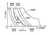
従来から、リアクトルとスイッチング素子とを有して直流電源からの直流電圧を昇圧する昇圧コンバータと、昇圧コンバータの出力電圧を交流電圧に変換すると共に当該交流電圧を用いて交流モータを駆動するインバータと、昇圧コンバータやインバータを制御する制御装置とを備えるモータ駆動装置が知られている(例えば、特許文献1および2参照)。これらのモータ駆動装置は、インバータによる電圧変換の変調率が値0〜値0.61の範囲となる正弦波PWM制御方式、変調率が値0.61〜値0.78の範囲となる過変調PWM制御方式および変調率が値0.78となる矩形制御方式という3つの方式の中の何れかに従ってインバータを制御可能に構成されている。すなわち、この種のモータ駆動装置では、各制御方式におけるインバータの変調率を考慮して、交流モータの動作領域のうち、低回転数域では正弦波PWM制御方式が用いられ、中回転数域では過変調PWM制御方式が用いられ、高回転数域では矩形波制御方式が用いられる。これにより、交流モータの低回転数域ではトルク変動を抑えて滑らかな出力特性を得ることが可能となり、中高回転域では交流モータの出力をより向上させることが可能となる。
ここで、上記従来のモータ駆動装置において用いられる矩形波制御方式は、正弦波PWM制御方式等に比べて制御精度(制御応答性)に劣るものの、交流モータの出力を向上させると共に銅損の発生やスイッチング損失を抑えてエネルギ効率を向上させることが可能なものである。従って、交流モータの動作領域における矩形波制御方式の適用範囲を拡大すれば、交流モータを含む電気駆動系の性能やエネルギ効率をより向上させることができるであろう。ただし、上述のような昇圧コンバータを含むモータ駆動装置では、昇圧コンバータの直流電源側とインバータ側とのそれぞれに平滑コンデンサが配置されることから、昇圧コンバータのリアクトルとこれら平滑コンデンサにより共振回路が構成され、交流モータの動作点が所定領域に含まれるときに昇圧コンバータで電圧や電流の共振が発生する。従って、矩形波制御方式の適用範囲を拡大するにあたっては、昇圧コンバータでの電圧や電流の共振をも考慮して、昇圧コンバータや平滑コンデンサに過大な電圧が電流が印加されないようにする必要がある。 Here, the rectangular wave control method used in the conventional motor driving device is inferior in control accuracy (control responsiveness) compared to the sine wave PWM control method and the like, but improves the output of the AC motor and generates copper loss. In addition, energy efficiency can be improved by suppressing switching loss. Therefore, if the application range of the rectangular wave control method in the operation region of the AC motor is expanded, the performance and energy efficiency of the electric drive system including the AC motor can be further improved. However, in the motor drive device including the boost converter as described above, a smoothing capacitor is arranged on each of the DC power supply side and the inverter side of the boost converter, so that a resonance circuit is configured by the reactor of the boost converter and these smoothing capacitors. When the operating point of the AC motor is included in the predetermined region, voltage or current resonance occurs in the boost converter. Therefore, in expanding the application range of the rectangular wave control method, it is necessary to prevent excessive voltage from being applied to the boost converter and the smoothing capacitor in consideration of voltage and current resonance in the boost converter. .
そこで、本発明による電動機駆動制御装置、それを備えた車両および電動機駆動制御方法は、直流電源側の電圧に対する電動機駆動回路側の電圧を調整可能な電圧調整手段での共振の発生に起因した不具合の発生を抑制しつつ電動機の出力やエネルギ効率の向上を図ることを主目的とする。 Therefore, the motor drive control device according to the present invention, the vehicle including the motor drive method, and the motor drive control method are disadvantageous due to the occurrence of resonance in the voltage adjusting means capable of adjusting the voltage on the motor drive circuit side with respect to the voltage on the DC power supply side. The main purpose is to improve the output of the motor and the energy efficiency while suppressing the occurrence of this.
本発明による電動機駆動制御装置、それを備えた車両および電動機駆動制御方法は、上述の目的を達成するために以下の手段を採っている。 The electric motor drive control device, the vehicle including the same, and the electric motor drive control method according to the present invention employ the following means in order to achieve the above-described object.
本発明による電動機駆動制御装置は、
直流電源からの電力を用いて電動機を駆動制御する電動機駆動制御装置であって、
PWM電圧と矩形波電圧とを選択的に用いて前記電動機を駆動することができる電動機駆動回路と、
リアクトルとコンデンサとを有すると共に前記直流電源側の電圧に対する前記電動機駆動回路側の電圧を調整可能な電圧調整手段と、
前記電動機駆動回路側の電圧が前記電動機の目標動作点に応じた目標電圧になるように前記電圧調整手段を制御すると共に、前記電動機の目標動作点が前記電圧調整手段で共振が発生するときの該電動機の動作点を含む所定の共振域に含まれるときに前記電動機駆動回路側の電圧が前記直流電源側の電圧よりも高い所定の目標電圧になるように前記電圧調整手段を制御する電圧制御手段と、
前記電圧調整手段により前記直流電源側の電圧に対する前記電動機駆動回路側の電圧が調整されていない状態と該直流電源側の電圧に対する該電動機駆動回路側の電圧が調整されている状態との双方のもとで前記PWM電圧を用いるPWM制御方式と前記矩形波電圧を用いる矩形波制御方式とを選択的に用いて前記電動機が目標トルクを出力するように前記電動機駆動回路を制御すると共に、前記電動機の目標動作点が前記共振域に含まれるときに前記PWM制御方式を用いて前記電動機駆動回路を制御する駆動回路制御手段と、
を備えるものである。An electric motor drive control device according to the present invention includes:
An electric motor drive control device for driving and controlling an electric motor using electric power from a DC power source,
An electric motor drive circuit capable of selectively driving the electric motor using a PWM voltage and a rectangular wave voltage;
Voltage adjusting means having a reactor and a capacitor and capable of adjusting the voltage on the electric motor driving circuit side with respect to the voltage on the DC power source side;
The voltage adjusting means is controlled so that the voltage on the electric motor drive circuit side becomes a target voltage corresponding to the target operating point of the electric motor, and when the target operating point of the electric motor causes resonance in the voltage adjusting means Voltage control for controlling the voltage adjusting means so that the voltage on the motor drive circuit side becomes a predetermined target voltage higher than the voltage on the DC power source side when included in a predetermined resonance range including the operating point of the motor Means,
Both the state where the voltage on the motor drive circuit side with respect to the voltage on the DC power source side is not adjusted by the voltage adjusting means and the state where the voltage on the motor drive circuit side with respect to the voltage on the DC power source side is adjusted. The motor driving circuit is controlled so that the motor outputs a target torque by selectively using a PWM control method using the PWM voltage and a rectangular wave control method using the rectangular wave voltage, and the electric motor Drive circuit control means for controlling the motor drive circuit using the PWM control method when the target operating point is included in the resonance range;
Is provided.
この電動機駆動制御装置では、電動機駆動回路側の電圧が電動機の目標動作点に応じた目標電圧になるように電圧調整手段が制御されると共に、電圧調整手段により直流電源側の電圧に対する電動機駆動回路側の電圧が調整されていない状態と調整されている状態との双方のもとでPWM電圧を用いるPWM制御方式と矩形波電圧を用いる矩形波制御方式とを選択的に用いて電動機が目標トルクを出力するように電動機駆動回路が制御される。このように、一般に電圧調整手段により直流電源側の電圧に対する電動機駆動回路側の電圧が調整されるときにのみ用いられる矩形波制御方式の適用範囲を電圧調整手段によって直流電源側の電圧に対する電動機駆動回路側の電圧が調整されていないときにまで拡げることにより、電圧調整手段に直流電源からの電圧を昇圧させる機会を減らしても電動機の出力を確保することが可能となり、電動機の駆動制御に伴うエネルギ効率をより向上させることができる。そして、この電動機駆動制御装置では、電動機の目標動作点が電圧調整手段で共振が発生するときの当該電動機の動作点を含む所定の共振域に含まれるときに、電動機駆動回路側の電圧が直流電源側の電圧よりも高い所定の目標電圧になるように電圧調整手段が制御されると共に、PWM制御方式を用いて電動機駆動回路が制御される。このように電動機の目標動作点が共振域に含まれるときに制御精度に優れるPWM制御方式を用いることにより、昇圧コンバータや平滑コンデンサに過大な電圧が作用したり過大な電流が流れてしまったりしないように電動機駆動回路をより適正に制御することが可能となる。また、電動機の目標動作点が共振域に含まれるときに例えば電動機駆動回路に供給される電圧を昇圧した上でPWM制御方式を用いて電動機駆動回路を制御することにより、変調率が比較的小さいPWM制御方式を用いても電動機の出力を良好に確保することが可能となる。従って、この電動機駆動制御装置によれば、直流電源側の電圧に対する電動機駆動回路側の電圧を調整可能な電圧調整手段での共振の発生に起因した過電圧や過電流といった不具合の発生を抑制しつつ電動機の出力やエネルギ効率の向上を図ることが可能となる。なお、ここでいう「PWM制御方式」は、正弦波PWM制御方式であると好ましいが、正弦波PWM制御方式と過変調PWM制御方式との双方であってもよい。 In this motor drive control device, the voltage adjustment means is controlled so that the voltage on the motor drive circuit side becomes a target voltage corresponding to the target operating point of the motor, and the motor drive circuit for the voltage on the DC power supply side is controlled by the voltage adjustment means. The motor is selectively torqued using a PWM control method that uses a PWM voltage and a rectangular wave control method that uses a rectangular wave voltage under both an unadjusted state and a regulated state. The motor drive circuit is controlled to output. As described above, the range of application of the rectangular wave control method generally used only when the voltage on the motor driving circuit side is adjusted with respect to the voltage on the DC power source side by the voltage adjusting means is the motor driving for the voltage on the DC power source side by the voltage adjusting means. By expanding to the time when the voltage on the circuit side is not adjusted, it becomes possible to secure the output of the motor even if the opportunity to boost the voltage from the DC power source to the voltage adjusting means is reduced, and accompanying the drive control of the motor Energy efficiency can be further improved. In this motor drive control device, when the target operating point of the motor is included in a predetermined resonance region including the operating point of the motor when resonance occurs in the voltage adjusting means, the voltage on the motor driving circuit side is DC The voltage adjusting means is controlled so as to be a predetermined target voltage higher than the voltage on the power supply side, and the motor drive circuit is controlled using the PWM control method. By using the PWM control method that has excellent control accuracy when the target operating point of the motor is included in the resonance range in this way, excessive voltage or excessive current does not flow to the boost converter or smoothing capacitor. Thus, the motor drive circuit can be controlled more appropriately. In addition, when the target operating point of the motor is included in the resonance region, for example, the voltage supplied to the motor driving circuit is boosted and then the motor driving circuit is controlled using the PWM control method, so that the modulation rate is relatively small. Even if the PWM control method is used, the output of the electric motor can be secured satisfactorily. Therefore, according to this motor drive control device, while suppressing the occurrence of problems such as overvoltage and overcurrent due to the occurrence of resonance in the voltage adjusting means capable of adjusting the voltage on the motor drive circuit side with respect to the voltage on the DC power supply side. It becomes possible to improve the output and energy efficiency of the electric motor. The “PWM control method” here is preferably a sine wave PWM control method, but may be both a sine wave PWM control method and an overmodulation PWM control method.
また、前記電動機の動作領域は、前記直流電源からの電圧が前記電圧調整手段により昇圧されない非昇圧領域と該直流電源からの電圧が該電圧調整手段により昇圧される昇圧領域とに予め区分けされると共に前記共振域は前記昇圧領域に含まれてもよく、前記電圧制御手段は、前記電動機の目標動作点が前記昇圧領域に含まれるときに前記電動機駆動回路に供給される電圧が前記電動機の目標動作点に応じた目標電圧に昇圧されるように前記電圧調整手段を制御するものであってもよい。このように電動機の動作領域を非昇圧領域と昇圧領域とに予め区分けした上で共振域を昇圧領域に含めておくことにより、電圧調整手段での共振の発生に起因した不具合の発生を容易かつ確実に抑制することが可能となる。 The operating region of the electric motor is divided into a non-boosting region where the voltage from the DC power source is not boosted by the voltage adjusting unit and a boosting region where the voltage from the DC power source is boosted by the voltage adjusting unit. In addition, the resonance region may be included in the boost region, and the voltage control unit is configured such that the voltage supplied to the motor drive circuit when the target operating point of the motor is included in the boost region is the target of the motor. The voltage adjusting unit may be controlled so as to be boosted to a target voltage corresponding to the operating point. Thus, by dividing the operating region of the motor into a non-boosting region and a boosting region in advance and including the resonance region in the boosting region, it is possible to easily generate a malfunction due to the occurrence of resonance in the voltage adjusting means. It becomes possible to suppress it reliably.
更に、前記駆動回路制御手段は、前記電動機の目標動作点および前記電動機駆動回路による電圧変換の変調率の少なくとも何れか一方と、該目標動作点および該変調率の少なくとも何れか一方と前記電動機駆動回路の制御方式との関係を規定する所定の制御方式設定制約とから定まる制御方式を用いて前記電動機駆動回路を制御するものであってもよい。これにより、PWM制御方式と矩形波制御方式とをより適正に使い分けすることが可能となる。 Further, the drive circuit control means includes at least one of a target operating point of the motor and a modulation rate of voltage conversion by the motor driving circuit, at least one of the target operating point and the modulation rate, and driving the motor. The motor drive circuit may be controlled using a control method determined from a predetermined control method setting constraint that defines a relationship with a circuit control method. As a result, the PWM control method and the rectangular wave control method can be properly used properly.
また、前記電動機駆動制御装置は、前記電圧調整手段で所定の度合いを超える共振が発生しているか否かを判定する共振発生判定手段を更に備えてもよく、前記共振発生判定手段により前記電圧調整手段で前記所定の度合いを超える共振が発生していると判断されたときに、前記電圧制御手段は前記電動機駆動回路に供給される電圧が所定の目標電圧に昇圧されるように前記電圧調整手段を制御してもよく、前記駆動回路制御手段は前記PWM制御方式を用いて前記電動機が前記目標トルクを出力するように前記電動機駆動回路を制御してもよい。これにより、電圧調整手段での共振の発生に起因した不具合の発生をより確実に抑制することが可能となる。 The motor drive control device may further include a resonance generation determination unit that determines whether or not resonance exceeding a predetermined degree is generated in the voltage adjustment unit, and the voltage adjustment is performed by the resonance generation determination unit. When it is determined by the means that resonance exceeding the predetermined degree is occurring, the voltage control means is configured to increase the voltage supplied to the motor drive circuit to a predetermined target voltage. The drive circuit control means may control the motor drive circuit using the PWM control method so that the motor outputs the target torque. As a result, it is possible to more reliably suppress the occurrence of defects due to the occurrence of resonance in the voltage adjusting means.
この場合、前記共振発生判定手段は、前記電動機駆動回路に供給される電圧の最大振幅に基づいて前記電圧調整手段で共振が発生しているか否かを判定するものであってもよい。これにより、共振の発生の有無をより適正に判断することが可能となる。 In this case, the resonance occurrence determination means may determine whether resonance has occurred in the voltage adjustment means based on the maximum amplitude of the voltage supplied to the electric motor drive circuit. This makes it possible to more appropriately determine whether or not resonance has occurred.
本発明による他の電動機駆動制御装置は、
直流電源からの電力を用いて電動機を駆動制御する電動機駆動制御装置であって、
正弦波PWM電圧と矩形波電圧とを選択的に用いて前記電動機を駆動することができる電動機駆動回路と、
リアクトルとコンデンサとを有すると共に前記直流電源側の電圧に対する前記電動機駆動回路側の電圧を調整可能な電圧調整手段と、
前記電動機駆動回路側の電圧が前記電動機の目標動作点に応じた目標電圧になるように前記電圧調整手段を制御する電圧制御手段と、
前記電圧調整手段により前記直流電源からの電圧が昇圧されていない状態と該直流電源からの電圧が昇圧されている状態との双方のもとで前記正弦波PWM電圧を用いる正弦波PWM制御方式と前記矩形波電圧を用いる矩形波制御方式とを選択的に用いて前記電動機が目標トルクを出力するように前記電動機駆動回路を制御すると共に、前記電圧調整手段により前記直流電源からの電圧が昇圧されていない状態で前記矩形波制御方式を用いて前記電動機駆動回路を制御している最中に前記電動機の目標動作点が前記電圧調整手段で共振が発生するときの該電動機の動作点を含む所定の共振域に含まれるときには、前記矩形波制御方式を用いると共に弱め界磁電流の増加を伴って前記電動機駆動回路を制御すると共に該矩形波制御方式から前記正弦波PWM制御方式への移行が可能になると該正弦波PWM制御方式を用いて前記電動機駆動回路を制御する駆動回路制御手段と、
を備えるものである。Another electric motor drive control device according to the present invention is:
An electric motor drive control device for driving and controlling an electric motor using electric power from a DC power source,
An electric motor drive circuit capable of driving the electric motor selectively using a sine wave PWM voltage and a rectangular wave voltage;
Voltage adjusting means having a reactor and a capacitor and capable of adjusting the voltage on the electric motor driving circuit side with respect to the voltage on the DC power source side;
Voltage control means for controlling the voltage adjusting means so that the voltage on the motor drive circuit side becomes a target voltage corresponding to a target operating point of the motor;
A sinusoidal PWM control method using the sinusoidal PWM voltage under both the state where the voltage from the DC power source is not boosted by the voltage adjusting means and the state where the voltage from the DC power source is boosted; The motor driving circuit is controlled so that the motor outputs a target torque selectively using a rectangular wave control method using the rectangular wave voltage, and the voltage from the DC power source is boosted by the voltage adjusting means. In a state where the motor operating circuit is being controlled using the rectangular wave control method in a state where the motor is not in operation, the target operating point of the motor includes the operating point of the motor when resonance occurs in the voltage adjusting means. When the rectangular wave control method is used, the rectangular wave control method is used, and the motor drive circuit is controlled with an increase in field weakening current. A drive circuit control means for controlling said motor drive circuit using the sinusoidal transition to PWM control method is enabled for the sinusoidal PWM control method,
Is provided.
この電動機駆動制御装置では、電動機駆動回路側の電圧が電動機の目標動作点に応じた目標電圧になるように電圧調整手段が制御されると共に、電圧調整手段により直流電源からの電圧が昇圧されていない状態と昇圧されている状態との双方のもとで正弦波PWM電圧を用いる正弦波PWM制御方式と矩形波電圧を用いる矩形波制御方式とを選択的に用いて電動機が目標トルクを出力するように電動機駆動回路が制御される。このように、一般に電圧調整手段により直流電源からの電圧が昇圧されるときにのみ用いられる矩形波制御方式の適用範囲を電圧調整手段によって直流電源からの電圧が昇圧されていないときにまで拡げることにより、電圧調整手段に直流電源からの電圧を昇圧させる機会を減らしても電動機の出力を確保することが可能となり、電動機の駆動制御に伴うエネルギ効率をより向上させることができる。そして、この電動機駆動制御装置では、電圧調整手段により直流電源からの電圧が昇圧されていない状態で矩形波制御方式を用いて電動機駆動回路が制御されている最中に電動機の目標動作点が電圧調整手段で共振が発生するときの当該電動機の動作点を含む所定の共振域に含まれるときには、矩形波制御方式を用いると共に弱め界磁電流の増加を伴って電動機駆動回路が制御されると共に矩形波制御方式から正弦波PWM制御方式への移行が可能になると正弦波PWM制御方式を用いて電動機駆動回路が制御される。このように矩形波制御方式の使用中に電動機の目標動作点が共振域に含まれるときに、そのまま矩形波制御方式を用いると共に弱め界磁電流の増加を伴って電動機駆動回路を制御すれば、電動機の誘起電圧(端子間電圧)を低下させることができるので、電圧調整手段に直流電源からの電圧を昇圧させることなく制御方式を正弦波PWM制御方式へと移行させることが可能となる。そして、電動機の誘起電圧が充分に低下した段階から正弦波PWM制御方式を用いることにより、昇圧コンバータや平滑コンデンサに過大な電圧が作用したり過大な電流が流れてしまったりしないように電動機駆動回路をより適正に制御すると共に電動機からの出力を充分に確保することができる。従って、この電動機駆動制御装置によっても、直流電源側の電圧に対する電動機駆動回路側の電圧を調整可能な電圧調整手段での共振の発生に起因した過電圧や過電流といった不具合の発生を抑制しつつ電動機の出力やエネルギ効率の向上を図ることが可能となる。 In this motor drive control device, the voltage adjusting means is controlled so that the voltage on the motor drive circuit side becomes a target voltage corresponding to the target operating point of the motor, and the voltage from the DC power source is boosted by the voltage adjusting means. The electric motor outputs a target torque by selectively using a sine wave PWM control method using a sine wave PWM voltage and a rectangular wave control method using a rectangular wave voltage under both a non-existing state and a boosted state. Thus, the motor drive circuit is controlled. As described above, the application range of the rectangular wave control method that is generally used only when the voltage from the DC power source is boosted by the voltage adjusting means is expanded to the time when the voltage from the DC power source is not boosted by the voltage adjusting means. As a result, the output of the electric motor can be ensured even if the opportunity for boosting the voltage from the DC power source to the voltage adjusting means is reduced, and the energy efficiency associated with the drive control of the electric motor can be further improved. In this motor drive control device, the target operating point of the motor is a voltage while the motor drive circuit is controlled using the rectangular wave control method in a state where the voltage from the DC power source is not boosted by the voltage adjusting means. When the adjustment means is included in a predetermined resonance range including the operating point of the motor when the resonance occurs, the rectangular wave control method is used and the motor drive circuit is controlled with the increase of the field weakening current and the rectangle is controlled. When the transition from the wave control method to the sine wave PWM control method becomes possible, the motor drive circuit is controlled using the sine wave PWM control method. In this way, when the target operating point of the motor is included in the resonance region during use of the rectangular wave control method, if the rectangular wave control method is used as it is and the motor drive circuit is controlled with an increase in field weakening current, Since the induced voltage (inter-terminal voltage) of the electric motor can be reduced, it is possible to shift the control method to the sine wave PWM control method without causing the voltage adjusting means to boost the voltage from the DC power supply. And, by using the sine wave PWM control method from the stage when the induced voltage of the motor is sufficiently lowered, the motor drive circuit prevents excessive voltage from acting on the boost converter and smoothing capacitor and excessive current from flowing. Can be controlled more appropriately, and sufficient output from the electric motor can be secured. Therefore, this motor drive control device also suppresses the occurrence of problems such as overvoltage and overcurrent caused by the occurrence of resonance in the voltage adjusting means capable of adjusting the voltage on the motor drive circuit side with respect to the voltage on the DC power supply side. It is possible to improve the output and energy efficiency.
本発明による更に他の電動機駆動制御装置は、
直流電源からの電力を用いて電動機を駆動制御する電動機駆動制御装置であって、
PWM電圧と矩形波電圧とを選択的に用いて前記電動機を駆動することができる電動機駆動回路と、
リアクトルとコンデンサとを有すると共に前記直流電源側の電圧に対する前記電動機駆動回路側の電圧を調整可能な電圧調整手段と、
前記電動機駆動回路側の電圧が前記電動機の目標動作点に応じた目標電圧になるように前記電圧調整手段を制御する電圧制御手段と、
前記電圧調整手段により前記直流電源側の電圧に対する前記電動機駆動回路側の電圧が調整されていない状態と該直流電源側の電圧に対する該電動機駆動回路側の電圧が調整されている状態との双方のもとで前記PWM電圧を用いるPWM制御方式と前記矩形波電圧を用いる矩形波制御方式とを選択的に用いて前記電動機が目標トルクを出力するように前記電動機駆動回路を制御する駆動回路制御手段とを備え、
前記リアクトルおよび前記コンデンサの諸元は、前記電圧調整手段で共振が発生するときの前記電動機の動作点を含む所定の共振域が該電動機の動作領域のうちの前記電圧調整手段により前記直流電源側の電圧に対する前記電動機駆動回路側の電圧が調整されず、かつ前記駆動回路制御手段により前記電動機駆動回路が前記PWM制御方式を用いて制御される領域に含まれるように定められていることを特徴とする。Still another electric motor drive control device according to the present invention includes:
An electric motor drive control device for driving and controlling an electric motor using electric power from a DC power source,
An electric motor drive circuit capable of selectively driving the electric motor using a PWM voltage and a rectangular wave voltage;
Voltage adjusting means having a reactor and a capacitor and capable of adjusting the voltage on the electric motor driving circuit side with respect to the voltage on the DC power source side;
Voltage control means for controlling the voltage adjusting means so that the voltage on the motor drive circuit side becomes a target voltage corresponding to a target operating point of the motor;
Both the state where the voltage on the motor drive circuit side with respect to the voltage on the DC power source side is not adjusted by the voltage adjusting means and the state where the voltage on the motor drive circuit side with respect to the voltage on the DC power source side is adjusted. Drive circuit control means for controlling the motor drive circuit so that the motor outputs a target torque by selectively using a PWM control method using the PWM voltage and a rectangular wave control method using the rectangular wave voltage. And
The specifications of the reactor and the capacitor are such that a predetermined resonance region including an operating point of the electric motor when resonance occurs in the voltage adjusting unit is on the side of the DC power source by the voltage adjusting unit in the operating region of the electric motor. The voltage on the motor drive circuit side with respect to the voltage of the motor is not adjusted, and the drive circuit control means determines that the motor drive circuit is included in a region controlled using the PWM control method. And
この電動機駆動制御装置では、電動機駆動回路側の電圧が電動機の目標動作点に応じた目標電圧になるように電圧調整手段が制御されると共に、電圧調整手段により直流電源側の電圧に対する電動機駆動回路側の電圧が調整されていない状態と調整されている状態との双方のもとでPWM電圧を用いるPWM制御方式と矩形波電圧を用いる矩形波制御方式とを選択的に用いて電動機が目標トルクを出力するように電動機駆動回路が制御される。このように、一般に電圧調整手段により直流電源側の電圧に対する電動機駆動回路側の電圧が調整されるときにのみ用いられる矩形波制御方式の適用範囲を電圧調整手段によって直流電源側の電圧に対する電動機駆動回路側の電圧が調整されていないときにまで拡げることにより、電圧調整手段に直流電源からの電圧を昇圧させる機会を減らしても電動機の出力を確保することが可能となり、電動機の駆動制御に伴うエネルギ効率をより向上させることができる。そして、この電動機駆動制御装置では、リアクトルおよびコンデンサの諸元が、電圧調整手段で共振が発生するときの電動機の動作点を含む所定の共振域が当該電動機の動作領域のうちの電圧調整手段により直流電源側の電圧に対する電動機駆動回路側の電圧が調整されず、かつ駆動回路制御手段により電動機駆動回路がPWM制御方式を用いて制御される領域に含まれるように定められている。これにより、電動機の目標動作点が共振域に含まれるときに、電圧調整手段に直流電源からの電圧を昇圧させることなく電動機からの出力を充分に確保すると共に、制御精度に優れるPWM制御方式を用いることで昇圧コンバータや平滑コンデンサに過大な電圧が作用したり過大な電流が流れてしまったりしないように電動機駆動回路をより適正に制御することができる。従って、この電動機駆動制御装置によっても、直流電源側の電圧に対する電動機駆動回路側の電圧を調整可能な電圧調整手段での共振の発生に起因した過電圧や過電流といった不具合の発生を抑制しつつ電動機の出力やエネルギ効率の向上を図ることが可能となる。 In this motor drive control device, the voltage adjustment means is controlled so that the voltage on the motor drive circuit side becomes a target voltage corresponding to the target operating point of the motor, and the motor drive circuit for the voltage on the DC power supply side is controlled by the voltage adjustment means. The motor is selectively torqued using a PWM control method that uses a PWM voltage and a rectangular wave control method that uses a rectangular wave voltage under both an unadjusted state and a regulated state. The motor drive circuit is controlled to output. As described above, the range of application of the rectangular wave control method generally used only when the voltage on the motor driving circuit side is adjusted with respect to the voltage on the DC power source side by the voltage adjusting means is the motor driving for the voltage on the DC power source side by the voltage adjusting means. By expanding to the time when the voltage on the circuit side is not adjusted, it becomes possible to secure the output of the motor even if the opportunity to boost the voltage from the DC power source to the voltage adjusting means is reduced, and accompanying the drive control of the motor Energy efficiency can be further improved. In this motor drive control device, the predetermined resonance region including the operating point of the electric motor when the resonance occurs in the voltage adjusting unit is determined by the voltage adjusting unit in the electric motor operating region. It is determined that the voltage on the motor drive circuit side with respect to the voltage on the DC power supply side is not adjusted, and the motor drive circuit is included in the region controlled by the PWM control method by the drive circuit control means. As a result, when the target operating point of the electric motor is included in the resonance range, the voltage adjustment means ensures a sufficient output from the electric motor without boosting the voltage from the DC power supply, and a PWM control method with excellent control accuracy. By using it, the motor drive circuit can be controlled more appropriately so that an excessive voltage does not act on the boost converter and the smoothing capacitor or an excessive current does not flow. Therefore, this motor drive control device also suppresses the occurrence of problems such as overvoltage and overcurrent caused by the occurrence of resonance in the voltage adjusting means capable of adjusting the voltage on the motor drive circuit side with respect to the voltage on the DC power supply side. It is possible to improve the output and energy efficiency.
本発明による車両は、上記何れかの電動機駆動制御装置と、該電動機駆動制御装置により駆動制御されて走行用の動力を出力する電動機とを備えるものである。従って、この車両は、上記何れかの電動機駆動制御装置と同様の作用効果を奏することができる。 A vehicle according to the present invention includes any one of the above-described motor drive control devices and an electric motor that is driven and controlled by the motor drive control device to output driving power. Therefore, this vehicle can achieve the same effects as any one of the above-described electric motor drive control devices.
本発明による電動機駆動制御方法は、
直流電源と、PWM電圧と矩形波電圧とを選択的に用いて電動機を駆動することができる電動機駆動回路と、リアクトルとコンデンサとを有すると共に前記直流電源側の電圧に対する前記電動機駆動回路側の電圧を調整可能な電圧調整手段とを用いて前記電動機を駆動制御する電動機駆動制御方法であって、
(a)前記電動機駆動回路側の電圧が前記電動機の目標動作点に応じた目標電圧になるように前記電圧調整手段を制御すると共に、前記電動機の目標動作点が前記電圧調整手段で共振が発生するときの該電動機の動作点を含む所定の共振域に含まれるときに前記電動機駆動回路側の電圧が前記直流電源側の電圧よりも高い所定の目標電圧になるように前記電圧調整手段を制御するステップと、
(b)前記電圧調整手段により前記直流電源側の電圧に対する前記電動機駆動回路側の電圧が調整されていない状態と該直流電源側の電圧に対する該電動機駆動回路側の電圧が調整されている状態との双方のもとで前記PWM電圧を用いるPWM制御方式と前記矩形波電圧を用いる矩形波制御方式とを選択的に用いて前記電動機が目標トルクを出力するように前記電動機駆動回路を制御すると共に、前記電動機の目標動作点が前記共振域に含まれるときに前記PWM制御方式を用いて前記電動機駆動回路を制御するステップと、
を含むものである。An electric motor drive control method according to the present invention includes:
A voltage on the motor driving circuit side with respect to the voltage on the DC power source side, including a motor driving circuit capable of selectively driving a motor using a DC power source, a PWM voltage and a rectangular wave voltage, and a reactor and a capacitor An electric motor drive control method for driving and controlling the electric motor using voltage adjusting means capable of adjusting
(A) The voltage adjusting means is controlled so that the voltage on the motor drive circuit side becomes a target voltage corresponding to the target operating point of the motor, and the target operating point of the motor is resonated by the voltage adjusting means. The voltage adjusting means is controlled so that the voltage on the motor drive circuit side becomes a predetermined target voltage higher than the voltage on the DC power source side when included in a predetermined resonance range including the operating point of the motor when And steps to
(B) a state in which the voltage on the motor drive circuit side with respect to the voltage on the DC power supply side is not adjusted by the voltage adjusting means, and a state in which the voltage on the motor drive circuit side with respect to the voltage on the DC power supply side is adjusted The motor drive circuit is controlled so that the motor outputs a target torque by selectively using a PWM control method using the PWM voltage and a rectangular wave control method using the rectangular wave voltage Controlling the motor drive circuit using the PWM control method when a target operating point of the motor is included in the resonance range;
Is included.
この方法によれば、直流電源側の電圧に対する電動機駆動回路側の電圧を調整可能な電圧調整手段での共振の発生に起因した過電圧や過電流といった不具合の発生を抑制しつつ電動機の出力やエネルギ効率の向上を図ることが可能となる。 According to this method, the output and energy of the motor are suppressed while suppressing the occurrence of problems such as overvoltage and overcurrent due to the occurrence of resonance in the voltage adjusting means that can adjust the voltage on the motor drive circuit side with respect to the voltage on the DC power supply side. Efficiency can be improved.
本発明による他の電動機駆動制御方法は、
直流電源と、正弦波PWM電圧と矩形波電圧とを選択的に用いて電動機を駆動することができる電動機駆動回路と、リアクトルとコンデンサとを有すると共に前記直流電源側の電圧に対する前記電動機駆動回路側の電圧を調整可能な電圧調整手段とを用いて前記電動機を駆動制御する電動機駆動制御方法であって、
前記電圧調整手段により前記直流電源からの電圧が昇圧されていない状態と該直流電源からの電圧が昇圧されている状態との双方のもとで前記正弦波PWM電圧を用いる正弦波PWM制御方式と前記矩形波電圧を用いる矩形波制御方式とを選択的に用いて前記電動機が目標トルクを出力するように前記電動機駆動回路を制御すると共に、前記電圧調整手段により前記直流電源からの電圧が昇圧されていない状態で前記矩形波制御方式を用いて前記電動機駆動回路を制御している最中に前記電動機の目標動作点が前記電圧調整手段で共振が発生するときの該電動機の動作点を含む所定の共振域に含まれるときには、前記矩形波制御方式を用いると共に弱め界磁電流の増加を伴って前記電動機駆動回路を制御すると共に、該矩形波制御方式から前記正弦波PWM制御方式への移行が可能になると該正弦波PWM制御方式を用いて前記電動機駆動回路を制御するステップと、
を含むものである。Another electric motor drive control method according to the present invention is as follows:
A motor drive circuit capable of driving a motor by selectively using a DC power source, a sine wave PWM voltage and a rectangular wave voltage; a reactor and a capacitor; and the motor drive circuit side relative to the DC power source side voltage An electric motor drive control method for driving and controlling the electric motor using voltage adjusting means capable of adjusting the voltage of
A sinusoidal PWM control system using the sinusoidal PWM voltage under both a state where the voltage from the DC power source is not boosted by the voltage adjusting means and a state where the voltage from the DC power source is boosted; The motor driving circuit is controlled so that the motor outputs a target torque selectively using a rectangular wave control method using the rectangular wave voltage, and the voltage from the DC power source is boosted by the voltage adjusting means. In a state where the motor operating circuit is being controlled using the rectangular wave control method in a state where the motor does not operate, the target operating point of the motor includes the operating point of the motor when resonance occurs in the voltage adjusting means The rectangular wave control method is used, the motor drive circuit is controlled with an increase in field weakening current, and the rectangular wave control method And controlling the electric motor drive circuit using the sinusoidal PWM control method when the transition is enabled for the sine-wave PWM control mode,
Is included.
この方法によっても、直流電源側の電圧に対する電動機駆動回路側の電圧を調整可能な電圧調整手段での共振の発生に起因した過電圧や過電流といった不具合の発生を抑制しつつ電動機の出力やエネルギ効率の向上を図ることが可能となる。 Even with this method, the output and energy efficiency of the motor can be suppressed while suppressing the occurrence of problems such as overvoltage and overcurrent due to the occurrence of resonance in the voltage adjusting means capable of adjusting the voltage on the motor drive circuit side with respect to the voltage on the DC power supply side. Can be improved.
次に、本発明を実施するための最良の形態を実施例を用いて説明する。 Next, the best mode for carrying out the present invention will be described using examples.
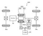
図1は、本発明の実施例に係るハイブリッド自動車20の概略構成図であり、図2は、ハイブリッド自動車20に含まれる電機駆動系の概略構成図である。これらの図面に示すように、実施例のハイブリッド自動車20は、エンジン22と、エンジン22の出力軸であるクランクシャフト26にダンパ28を介して接続された3軸式の動力分配統合機構30と、動力分配統合機構30に接続された発電可能なモータMG1と、動力分配統合機構30に接続された車軸としてのリングギヤ軸32aに取り付けられた減速ギヤ35と、この減速ギヤ35を介してリングギヤ軸32aに接続されたモータMG2と、直流電力を交流電力に変換してモータMG1,MG2に供給可能なインバータ41,42と、バッテリ50からの電力を電圧変換してインバータ41,42に供給可能な昇圧コンバータ55と、ハイブリッド自動車20の全体をコントロールするハイブリッド用電子制御ユニット(以下、「ハイブリッドECU」という)70等とを備えるものである。 FIG. 1 is a schematic configuration diagram of a
エンジン22は、ガソリンや軽油といった炭化水素系の燃料の供給を受けて動力を出力する内燃機関であり、エンジン用電子制御ユニット(以下、「エンジンECU」という)24による燃料噴射量や点火時期、吸入空気量等の制御を受けている。エンジンECU24には、エンジン22に対して設けられて当該エンジン22の運転状態を検出する各種センサからの信号が入力される。そして、エンジンECU24は、ハイブリッドECU70と通信しており、ハイブリッドECU70からの制御信号や上記センサからの信号等に基づいてエンジン22を運転制御すると共に必要に応じてエンジン22の運転状態に関するデータをハイブリッドECU70に出力する。 The
動力分配統合機構30は、外歯歯車のサンギヤ31と、このサンギヤ31と同心円上に配置された内歯歯車のリングギヤ32と、サンギヤ31に噛合すると共にリングギヤ32に噛合する複数のピニオンギヤ33と、複数のピニオンギヤ33を自転かつ公転自在に保持するキャリア34とを備え、サンギヤ31とリングギヤ32とキャリア34とを回転要素として差動作用を行う遊星歯車機構として構成されている。機関側回転要素としてのキャリア34にはエンジン22のクランクシャフト26が、サンギヤ31にはモータMG1が、車軸側回転要素としてのリングギヤ32にはリングギヤ軸32aを介して減速ギヤ35がそれぞれ連結されており、動力分配統合機構30は、モータMG1が発電機として機能するときにはキャリア34から入力されるエンジン22からの動力をサンギヤ31側とリングギヤ32側とにそのギヤ比に応じて分配し、モータMG1が電動機として機能するときにはキャリア34から入力されるエンジン22からの動力とサンギヤ31から入力されるモータMG1からの動力を統合してリングギヤ32側に出力する。リングギヤ32に出力された動力は、リングギヤ軸32aからギヤ機構37およびデファレンシャルギヤ38を介して最終的に駆動輪である車輪39a,39bに出力される。 The power distribution and
モータMG1およびモータMG2は、何れも内部に永久磁石が埋め込まれたロータと三相コイルが巻回されたステータとを有する同期発電電動機として構成されており、インバータ41,42を介して直流電源であるバッテリ50と電力のやり取りを行う。インバータ41,42は、図2に示すように、6つのトランジスタT11〜T16またはT21〜26とトランジスタT11〜T16またはT21〜T26に逆方向に並列接続された6つのダイオードD11〜D16またはD21〜D26とにより構成されている。トランジスタT11〜T16,T21〜T26は、それぞれインバータ41,42が電力ライン54として共用する正極母線54aと負極母線54bとに対してソース側とシンク側になるよう2個ずつ対をなすように配置されており、対となるトランジスタ同士の接続点の各々にモータMG1,MG2の三相コイル(U相、V相、W相)の各々が接続されている。従って、正極母線54aと負極母線54bとの間に電圧が作用している状態で対をなすトランジスタT11〜T16,T21〜T26のオン時間の割合を制御することにより三相コイルに回転磁界を形成してモータMG1,MG2を回転駆動することが可能となる。また、インバータ41,42は、正極母線54aと負極母線54bとを共用しているから、モータMG1,MG2の何れかで発電される電力を他のモータに供給することができる。そして、正極母線54aと負極母線54bとには電圧を平滑化する平滑コンデンサ57が接続されている。 Each of the motor MG1 and the motor MG2 is configured as a synchronous generator motor having a rotor in which a permanent magnet is embedded and a stator around which a three-phase coil is wound. It exchanges power with a
昇圧コンバータ55は、システムメインリレー56を介してバッテリ50と接続されており、図2に示すように、2つのトランジスタT31(上アーム)およびトランジスタT32(下アーム)と、トランジスタT31,T32に逆方向に並列接続された2つのダイオードD31,D32と、リアクトルLとを含む。2つのトランジスタT31,T32は、それぞれインバータ41,42の正極母線54aと負極母線54bとに接続されており、両者の接続点にリアクトルLが接続されている。また、リアクトルLと負極母線54bとには、システムメインリレー56を介してバッテリ50の正極端子と負極端子とが接続されると共に、昇圧コンバータ55のバッテリ50側の電圧を平滑化する平滑コンデンサ59が接続されている。更に、平滑コンデンサ59の端子間には第2電圧センサ92が設置されており、この第2電圧センサ92の検出値を用いて昇圧コンバータ55の昇圧前電圧(直流電源側の電圧)VLが取得される。これにより、トランジスタT31,T32をスイッチング制御することによりバッテリ50側からの直流電力の電圧(昇圧前電圧VL)を昇圧してインバータ41,42に供給することができる。この場合、インバータ41,42に印加され得る昇圧コンバータ55による昇圧後電圧(電動機駆動回路側の電圧)VHは、平滑コンデンサ57の端子間に設置された第3電圧センサ93の検出値を用いて取得される。また、昇圧コンバータ55のトランジスタT31,T32をスイッチング制御することにより、正極母線54aと負極母線54bとに作用している直流電圧を降圧してバッテリ50を充電することもできる。
これらのインバータ41,42や昇圧コンバータ55は、何れもモータ用電子制御ユニット(以下、「モータECU」という)40により制御され、それによりモータMG1,MG2が駆動制御される。モータECU40には、例えばモータMG1,MG2の回転子の回転位置を検出する回転位置検出センサ43,44からの信号や、第2および第3電圧センサ92,93からの電圧VLおよびVH、電流センサ95v,95w,96v,96w(図2参照)により検出されるモータMG1,MG2に印加される相電流といったモータMG1,MG2の駆動制御に必要な信号が入力される。また、モータECU40からは、インバータ41,42へのスイッチング制御信号や、システムメインリレー56への駆動信号、昇圧コンバータ55へのスイッチング制御信号等が出力される。更に、モータECU40は、バッテリECU52やハイブリッドECU70と通信しており、上記センサからの信号に加えてバッテリECU52からの信号、ハイブリッドECU70からの制御信号をも用いてモータMG1,MG2を駆動制御する。加えて、モータECU40は、回転位置検出センサ43,44からの信号に基づいてモータMG1,MG2の回転数Nm1,Nm2といったモータMG1,MG2の運転状態に関するデータを計算・取得し、必要に応じてこれらのデータをハイブリッドECU70等に出力する。 The
バッテリ50は、実施例ではニッケル水素二次電池あるいはリチウムイオン二次電池として構成されており、バッテリ用電子制御ユニット(以下、「バッテリECU」という)52によって管理されている。バッテリECU52には、バッテリ50を管理するのに必要な信号、例えば、バッテリ50の端子間に設置された第1電圧センサ91からの端子間電圧VB、バッテリ50の出力端子に接続された電力ライン54に取り付けられた図示しない電流センサからの充放電電流、バッテリ50に取り付けられた温度センサ51からのバッテリ温度Tb等が入力されている。バッテリECU52は、必要に応じてバッテリ50の状態に関するデータを通信によりハイブリッドECU70やエンジンECU24に出力する。更に、バッテリECU52は、バッテリ50を管理するために、電流センサにより検出された充放電電流の積算値に基づいて残容量SOCを算出したり、当該残容量SOCに基づいてバッテリ50の充放電要求パワーPb*を算出したり、残容量SOCと電池温度Tbとに基づいてバッテリ50の充電に許容される電力である充電許容電力としての入力制限Winとバッテリ50の放電に許容される電力である放電許容電力としての出力制限Woutとを算出したりする。バッテリ50の入出力制限Win,Woutは、バッテリ温度Tbに基づいて入出力制限Win,Woutの基本値を設定すると共に、バッテリ50の残容量(SOC)に基づいて出力制限用補正係数と入力制限用補正係数とを設定し、設定した入出力制限Win,Woutの基本値に補正係数を乗じることにより設定可能である。 In the embodiment, the
ハイブリッドECU70は、CPU72を中心とするマイクロプロセッサとして構成されており、CPU72の他に処理プログラムを記憶するROM74、データを一時的に記憶するRAM76、図示しない入出力ポートおよび通信ポート等を備える。ハイブリッドECU70には、イグニッションスイッチ(スタートスイッチ)80からのイグニッション信号、シフトレバー81の操作位置であるシフトポジションSPを検出するシフトポジションセンサ82からのシフトポジションSP、アクセルペダル83の踏み込み量を検出するアクセルペダルポジションセンサ84からのアクセル開度Acc、ブレーキペダル85の踏み込み量を検出するブレーキペダルストロークセンサ86からのブレーキペダルストロークBS、車速センサ87からの車速V等が入力ポートを介して入力される。また、ハイブリッドECU70は、上述したようにエンジンECU24やモータECU40、バッテリECU52等と通信ポートを介して接続されており、エンジンECU24やモータECU40、バッテリECU52等と各種制御信号やデータのやり取りを行っている。 The
そして、ハイブリッドECU70は、ハイブリッド自動車20の走行時に、基本的に、運転者のアクセルペダル83の踏み込み量に対応するアクセル開度Accと車速Vとに基づいて車軸としてのリングギヤ軸32aに出力すべき要求トルクTr*を計算すると共に、この要求トルクTr*に基づくトルクがリングギヤ軸32aに出力されるようにエンジン22の目標回転数Ne*や目標トルクTe*、モータMG1の目標トルクを示すトルク指令Tm1*、モータMG2の目標トルクを示すトルク指令Tm2*を設定する。ここで、実施例のハイブリッド自動車20におけるエンジン22とモータMG1およびMG2との運転制御方式には、トルク変換運転モードや充放電運転モード、モータ運転モード等が含まれる。トルク変換運転モードのもとで、ハイブリッドECU70は、要求トルクTr*に見合う動力(パワー)がエンジン22から出力されるように目標回転数Ne*および目標トルクTe*を設定すると共に、エンジン22から出力される動力のすべてが動力分配統合機構30とモータMG1およびMG2とによってトルク変換されてリングギヤ軸32aに出力されるようにモータMG1およびMG2に対するトルク指令Tm1*,Tm2*を設定する。また、充放電運転モードのもとで、ハイブリッドECU70は、要求トルクTr*とバッテリ50の充放電に要求される充放電要求パワーPb*との和に見合う動力(パワー)がエンジン22から出力されるように目標回転数Ne*および目標トルクTe*を設定すると共に、バッテリ50の充放電を伴ってエンジン22から出力される動力の全部または一部が動力分配統合機構30とモータMG1およびMG2とによりトルク変換されて要求トルクTR*に応じたトルクがリングギヤ軸32aに出力されるようモータMG1およびMG2に対するトルク指令Tm1*,Tm2*を設定する。更に、モータ運転モードのもとで、ハイブリッドECU70は、エンジン22の運転を停止させると共にモータMG2にのみ要求トルクTr*に見合うトルクをリングギヤ軸32aに出力させる。この場合、ハイブリッドECU70は、エンジン22の目標回転数Ne*や目標トルクTe*、モータMG1に対するトルク指令Tm1*をそれぞれ値0に設定すると共に、モータMG2に対するトルク指令Tm2*を要求トルクTr*や動力分配統合機構30のギヤ比ρ、減速ギヤ35のギヤ比Gr等に基づいて設定する。 When the
このようにして、ハイブリッドECU70によりエンジン22の目標回転数Ne*や目標トルクTe*、モータMG1に対するトルク指令Tm1*、モータMG2に対するトルク指令Tm2*が設定されると、目標回転数Ne*および目標トルクTe*がエンジンECU24に送信されると共に、トルク指令Tm1*,Tm2*がモータECU40に送信される。そして、エンジンECU24は、ハイブリッドECU70からの目標回転数Ne*や目標トルクTe*が得られるようにエンジン22を制御する。また、モータECU40は、ハイブリッドECU70からのトルク指令Tm1*に従ってモータMG1が駆動されると共にハイブリッドECU70からのトルク指令Tm2*に従ってモータMG2が駆動されるようにインバータ41,42のスイッチング制御を行なう。ここで、実施例のモータECU40は、モータMG1およびMG2をトルク指令Tm1*,Tm2*と回転数Nm1,Nm2とに応じて、正弦波PWM電圧を用いる正弦波PWM制御方式、過変調PWM電圧を用いる過変調PWM制御方式および矩形波電圧を用いる矩形波制御方式という3つの制御方式の何れかによりインバータ41および42をスイッチング制御する。正弦波PWM制御方式は、一般に「PWM制御」と称されるものであり、正弦波状の電圧指令値と三角波等の搬送波との電圧差に応じてトランジスタT11〜T16、トランジスタT21〜26をオン/オフ制御することにより、正弦波状の基本波成分をもった出力電圧(PWM電圧)を得る方式である。正弦波PWM制御方式を用いた場合、昇圧コンバータ55(平滑コンデンサ57)から供給される昇圧後電圧(インバータ入力電圧)VHに対する出力電圧(基本波成分の振幅)の割合である変調率Kmdをおおよそ値0〜値0.61の範囲内に設定することができる。また、過変調PWM制御方式は、搬送波の振幅を縮小するようにを歪ませた上で上述の正弦波PWM制御方式と同様の制御を行なうものであり、変調率をおおよそ値0.61〜0.78の範囲内に設定可能とするものである。更に、矩形波制御方式は、理論上、最大の振幅をもった基本波成分を発生させることができるものであって、振幅一定の矩形電圧の位相をトルク指令に応じて変化させることでモータトルクを制御可能とするものである。この矩形波制御方式を用いた場合、変調率Kmdは一定値(おおよそ値0.78)となる。なお、インバータ41,42(モータMG1,MG2)の制御精度(制御応答性)は、正弦波PWM制御方式、過変調PWM制御方式、矩形波制御方式の順に低下していくことになるが、矩形波制御方式を用いることにより、直流電源の電圧利用率を向上させる共に、銅損の発生やスイッチング損失を抑えてエネルギ効率を向上させることが可能となる。また、モータMG1,MG2の回転数が高まる高回転域においては、基本的に制御方式として矩形波制御方式が用いられることになるが、この場合には、インバータ41,42に供給される電圧である昇圧後電圧VHがモータMG1,MG2で発生する誘起電圧よりも高くなるように弱め界磁電流を供給する弱め界磁制御が実行される。そして、実施例のハイブリッド自動車20では、モータMG1,MG2の目標動作点(トルク指令Tm1*,Tm2*および回転数Nm1,Nm2)に応じてバッテリ50の定格電圧(例えばDC288V)が所定電圧(例えば最大650V)まで昇圧されるようにモータECU40により昇圧コンバータ55が制御される。 In this way, when the
次に、実施例のハイブリッド自動車20においてモータECU40により実行される昇圧コンバータ55やインバータ41,42の制御手順について説明する。図3は、実施例のモータECU40により所定時間おきに実行される昇圧制御ルーチンの一例を示すフローチャートである。 Next, the control procedure of the
図3の昇圧制御ルーチンの開始に際して、モータECU40の図示しないCPUは、ハイブリッドECU70からのモータMG1およびMG2に対するトルク指令Tm1*,Tm2*やモータMG1およびMG2の現在の回転数Nm1,Nm2、昇圧前電圧VL、昇圧後電圧VH、昇圧後電圧VHの最大振幅平均値VHapといった制御に必要なデータの入力処理を実行する(ステップS100)。なお、昇圧後電圧VHの最大振幅平均値VHapは、第3電圧センサ93を用いてサンプリングされる昇圧後電圧VHの振幅の最大値を過去数回分だけ平均化した値である。ステップS100のデータ入力処理の後、モータMG1,MG2に対するトルク指令Tm1*,Tm2*と、モータMG1,MG2の回転数Nm1,Nm2と、モータMG1およびMG2のそれぞれについて予め定められてモータECU40の図示しない記憶装置に記憶されている目標昇圧後電圧設定用マップとを用いて、ハイブリッド自動車20の走行状態に応じた昇圧後電圧VHの目標値である目標昇圧後電圧VHtagを設定する(ステップS110)。実施例では、モータMG1用の目標昇圧後電圧設定用マップから当該モータMG1の目標動作点(トルク指令Tm1*および現在の回転数Nm1)に対応して導出される値と、モータMG2用の目標昇圧後電圧設定用マップから当該モータMG2の目標動作点(トルク指令Tm2*および現在の回転数Nm2)に対応して導出される値との大きい方が目標昇圧後電圧VHtagとして設定される。 At the start of the boost control routine of FIG. 3, the CPU (not shown) of the
図4に目標昇圧後電圧設定用マップの一例を示す。同図は、目標昇圧後電圧設定用マップのトルク指令およびモータ回転数の値が共に正となる領域(第1象限)を例示するものであり、図4からわかるように、目標昇圧後電圧設定用マップは、モータMG1,MG2の動作領域をバッテリ50側の昇圧前電圧VLが昇圧コンバータ55により昇圧されない非昇圧領域と昇圧される昇圧領域とに区分けするように作成されている。実施例では、モータMG1,MG2の動作領域のうち、モータMG1,MG2からトルク指令Tm1*,Tm2*に応じたトルクを出力させるためにバッテリ50側の昇圧前電圧VLの昇圧が不可欠である領域を求めた上で、それ以外の領域の動作点(トルク指令および回転数)ごとに、バッテリ50側の昇圧前電圧VLを昇圧コンバータ55により昇圧しないときとバッテリ50側の昇圧前電圧VLを昇圧コンバータ55により昇圧したときとでモータMG1,MG2、インバータ41,42,バッテリ50、昇圧コンバータ55等を含む電気駆動系における効率を比較し、基本的に、当該効率が昇圧時よりも非昇圧時に高くなる動作点を非昇圧領域に含めると共に、当該効率が非昇圧時よりも昇圧時に高くなる動作点を昇圧領域に含めることにより、目標昇圧後電圧設定用マップを作成している。これにより、基本的には、図4において二点鎖線で示すような境界線により、モータ回転数の絶対値が低い側が非昇圧領域と規定されると共にモータ回転数の絶対値が高い側が昇圧領域と規定される。また、実施例では、昇圧領域の各動作点における誘起電圧等やインバータ41,42の制御方式における変調率Kmd等に基づいて、バッテリ50の定格電圧から昇圧後電圧VHの最大値Vmaxまでの間で、図4に示すような等電圧ラインV1〜V3が定められており、昇圧領域に含まれる動作点については、バッテリ50の定格電圧、等電圧ラインV1〜V3および昇圧後電圧VHの最大値Vmaxとの間を線形補間等することにより、それぞれの目標昇圧後電圧VHtagが予め定められている。なお、非昇圧領域については、例えばバッテリ50の定格電圧といった昇圧領域における目標昇圧後電圧VHtagよりも小さい一定値が目標昇圧後電圧VHtagとして定められている。 FIG. 4 shows an example of the target post-boost voltage setting map. This figure exemplifies a region (first quadrant) in which both the torque command and the motor rotation speed value in the target post-boost voltage setting map are positive. As can be seen from FIG. 4, the target post-boost voltage setting is shown. The map for use is created so that the operation region of the motors MG1 and MG2 is divided into a non-boosting region where the pre-boosting voltage VL on the
ところで、実施例のハイブリッド自動車20では、昇圧コンバータ55のインバータ41,42側の端子間とバッテリ50側の端子間とのそれぞれに平滑コンデンサ57,59が配置されていることから、昇圧コンバータ55のリアクトルLとこれら平滑コンデンサ57,59により共振回路が構成され、モータMG1,MG2の動作点が所定の領域に含まれるときに昇圧コンバータ55で電圧や電流の共振が発生する。これを踏まえて、実施例のハイブリッド自動車20では、昇圧コンバータ55で共振が発生するときのモータMG1,MG2の動作点を含む領域である共振域を予め実験・解析を経て特定した上で、当該共振域を図4に示すように上述の昇圧領域に含むものとして目標昇圧後電圧設定用マップを作成している。図4に示す例では、電動機駆動系の効率から定まる非昇圧領域と昇圧領域との境界(図4の二点鎖線参照)付近に共振域が存在しており、このような場合には、共振域を昇圧領域に含めるべく非昇圧領域と昇圧領域との境界である昇圧ラインが非昇圧領域側に張り出すことになる。また、昇圧領域に含まれる共振域における目標昇圧後電圧VHtagは、共振域に含まれる動作点に対応したトルクや誘起電圧、モータMG1またはMG2の目標動作点が共振域に含まれるときに用いられるインバータ41,42の制御方式における変調率Kmd等に基づいて定められる。なお、非昇圧領域から昇圧領域への移行時に用いられる昇圧ラインと昇圧領域から非昇圧領域への移行時に用いられる昇圧ラインとは同一とされてもよいが、例えば昇圧領域から非昇圧領域への移行が非昇圧領域から昇圧領域への移行よりもモータ回転数がより低い領域で実行されるように両者の間にヒステリシスを設けてもよい。 By the way, in the
さて、ステップS110にて上述のようにして目標昇圧後電圧VHtagを設定したならば、モータMG1,MG2に対するトルク指令Tm1*,Tm2*と、モータMG1,MG2の回転数Nm1,Nm2と、モータMG1およびMG2のそれぞれについて予め定められてモータECU40の図示しない記憶装置に記憶されている制御方式設定用マップとを用いて、モータMG1に対応したインバータ41とモータMG2に対応したインバータ42との制御に用いられる制御方式を決定すると共に、決定した制御方式が正弦波PWM制御方式、過変調PWM制御方式および矩形波制御方式の何れであるかを示す制御方式フラグFmod1,Fmod2を設定する(ステップS120)。ステップS120において、制御方式フラグFmod1は、モータMG1用の制御方式設定用マップから当該モータMG1の目標動作点(トルク指令Tm1*および現在の回転数Nm1)に対応して導出される制御方式が正弦波PWM制御方式であれば値0に、過変調PWM制御方式であれば値1に、矩形波制御方式であれば値2に設定される。同様に、制御方式フラグFmod2は、モータMG2用の制御方式設定用マップから当該モータMG2の目標動作点(トルク指令Tm2*および現在の回転数Nm2)に対応して導出される制御方式が正弦波PWM制御方式であれば値0に、過変調PWM制御方式であれば値1に、矩形波制御方式であれば値2に設定される。 If the target boosted voltage VHtag is set in step S110 as described above, torque commands Tm1 *, Tm2 * for the motors MG1, MG2, the rotational speeds Nm1, Nm2 of the motors MG1, MG2, and the motor MG1. And MG2 are used to control the
図5に制御方式設定用マップの一例を示す。同図は、制御方式設定用マップのトルク指令およびモータ回転数の値が共に正となる領域(第1象限)を例示するものであり、図5からわかるように、制御方式設定用マップは、上述の目標昇圧後電圧設定用マップに対応付けられると共にモータMG1,MG2の動作領域を正弦波PWM制御方式が用いられる領域と過変調PWM制御方式が用いられる領域と矩形波制御方式が用いられる領域とに区分けするように作成されている。また、実施例では、上記昇圧ラインにより規定される非昇圧領域と昇圧領域との双方が、基本的にモータ回転数が低い側から順番に、正弦波PWM制御方式が用いられる領域と過変調PWM制御方式が用いられる領域と矩形波制御方式が用いられる領域とにそれぞれ区分けされている。すなわち、実施例のハイブリッド自動車20では、昇圧コンバータ55によりバッテリ50側の昇圧前電圧VLが昇圧されていない状態と昇圧されている状態との双方のもとで正弦波PWM制御方式と過変調PWM制御方式と矩形波制御方式とを選択的に用いてモータMG1,MG2がトルク指令Tm1*,Tm2*に基づくトルクを出力するようにインバータ41,42が制御されるのである。これにより、一般に昇圧コンバータ55によりバッテリ50側の昇圧前電圧VLが昇圧されるときにのみ用いられる矩形波制御方式の適用範囲を昇圧コンバータ55によってバッテリ50側の昇圧前電圧VLが昇圧されないときにまで拡げることにより、昇圧コンバータ55にバッテリ50側の昇圧前電圧VLを昇圧させる機会を減らしてもモータMG1,MG2の出力を確保することが可能となり、モータMG1,MG2の駆動制御に伴うエネルギ効率をより向上させることができる。更に、実施例の制御方式設定用マップは、図5に示すように昇圧コンバータ55で共振が発生するときのモータMG1またはMG2の動作点を含む領域である共振域での制御方式が正弦波PWM制御方式となると共に、モータMG1およびMG2の一方の目標動作点が共振域に含まれるときのモータMG1およびMG2の他方の目標動作点が含まれる領域での制御方式が正弦波PWM制御方式となるように作成されている。 FIG. 5 shows an example of the control method setting map. This figure exemplifies a region (first quadrant) in which both the torque command and the motor rotation speed value of the control method setting map are positive. As can be seen from FIG. Corresponding to the above-described target post-boost voltage setting map, the operation areas of the motors MG1 and MG2 are the area where the sine wave PWM control method is used, the area where the overmodulation PWM control method is used, and the area where the rectangular wave control method is used. It is created to be divided into and. In the embodiment, both the non-boosting region and the boosting region defined by the boosting line are basically the same as the region in which the sine wave PWM control method is used, and the overmodulation PWM in order from the low motor rotation speed. The area is divided into an area where the control method is used and an area where the rectangular wave control method is used. That is, in the
ステップS120の処理の後、例えばステップS110にて設定した目標昇圧後電圧VHtagとステップS100にて入力した昇圧前電圧VLとを比較することにより昇圧コンバータ55にバッテリ50側の昇圧前電圧VLを昇圧させるか否かを判定する(ステップS130)。そして、バッテリ50側の昇圧前電圧VLを昇圧させるべき場合には、ステップS110にて設定した目標昇圧後電圧VHtagと、本ルーチンの前回実行時における昇圧後電圧指令VH*に予め定められた昇圧レートΔVを加算した値との小さい方を昇圧後電圧指令VH*として設定する(ステップS140)。なお、昇圧レートΔVは、昇圧後電圧VHを目標昇圧後電圧VHtagまで昇圧させるときの単位時間dtあたりの電圧の変化量であり、一定値とされてもよく、可変値とされてもよい。そして、設定した昇圧後電圧指令VH*やステップS100にて入力した昇圧前電圧VLおよび昇圧後電圧VHに基づいて、昇圧後電圧VHが昇圧後電圧指令VH*となるように昇圧コンバータ55のトランジスタT31,T32のスイッチング制御を実行し(ステップS150)、再度ステップS100以降の処理を実行する。これにより、実施例のハイブリッド自動車20では、モータMG1またはMG2の目標動作点(トルク指令および回転数)が昇圧コンバータ55で共振が発生するときのモータMG1,MG2の動作点を含む領域である共振域に含まれるときには、インバータ41,42に供給される電圧である昇圧後電圧VHが目標昇圧後電圧VHtagまで昇圧されるように昇圧コンバータ55が制御されると共に、正弦波PWM制御方式を用いてインバータ41,42が制御されることになる。 After the process of step S120, for example, the boosted voltage VL on the
また、ステップS130にてバッテリ50側の昇圧前電圧VLを昇圧させる必要がないと判断された場合には、ステップS100にて入力した昇圧後電圧VHの最大振幅平均値VHapが予め定められた閾値Vref(例えば、50V)以上であるか否かを判定する(ステップS160)。そして、最大振幅平均値VHapが閾値Vref以上であってインバータ41,42が過変調PWM制御方式や矩形波制御方式を用いて制御されているとその影響を抑制しきれない程度の共振が昇圧コンバータ55で発生しているとみなされる場合には、目標昇圧後電圧VHtagを例えばバッテリ50の定格電圧よりも高い所定値V1に再設定すると共に(ステップS170)、インバータ41および42の制御方式を正弦波PWM制御方式とすべく制御方式フラグFmod1およびFmod2をそれぞれ値0に設定する(ステップS180)。そして、上記ステップS140およびS150の処理を実行し、再度ステップS100以降の処理を実行する。これにより、実施例のハイブリッド自動車20では、モータMG1およびMG2の目標動作点(トルク指令および回転数)が予め定められた共振域に含まれていない場合であっても、昇圧後電圧VHの値に基づいて所定の度合いを超える共振が発生しているとみなされる場合には、インバータ41,42に供給される電圧である昇圧後電圧VHが目標昇圧後電圧VHtagまで昇圧されるように昇圧コンバータ55が制御されると共に、モータMG1およびMG2がトルク指令Tm1*,Tm2*に応じたトルクを出力するように正弦波PWM制御方式を用いてインバータ41,42が制御されることになる。一方、ステップS130にてバッテリ50側の昇圧前電圧VLを昇圧させる必要がないと判断されると共に、ステップS160にて昇圧後電圧VHの最大振幅平均値VHapが閾値Vref未満である判断された場合には、制御上の観点から昇圧コンバータ55のスイッチング制御時に用いられる昇圧後電圧指令VH*をステップS100にて入力した昇圧後電圧VHに設定した上で(ステップS190)、昇圧コンバータ55を昇圧動作させるためのスイッチング制御を実行することなく、再度ステップS100以降の処理を実行する。 If it is determined in step S130 that the voltage VL before boosting on the
以上説明したように、実施例のハイブリッド自動車20では、インバータ41,42側の電圧である昇圧後電圧VHがモータMG1,MG2の目標動作点に応じた目標昇圧後電圧VHtagになるように昇圧コンバータ55が制御されると共に、昇圧コンバータ55によりバッテリ50側の昇圧前電圧VLが昇圧されない状態と昇圧される状態との双方のもとで正弦波PWM制御方式と過変調PWM制御方式と矩形波制御方式とを選択的に用いてモータMG1,MG2がトルク指令Tm1*,Tm2*に応じたトルクを出力するようにインバータ41,42が制御される。このように、一般に昇圧コンバータ55によりバッテリ50側の昇圧前電圧VLが昇圧されるときにのみ用いられる矩形波制御方式の適用範囲を昇圧コンバータ55によってバッテリ50側の昇圧前電圧VLが昇圧されていないときにまで拡げることにより、非昇圧領域を拡大して昇圧コンバータ55にバッテリ50側の昇圧前電圧VLを昇圧させる機会を減らしてもモータMG1,MG2の出力を確保することが可能となり、モータMG1,MG2の駆動制御に伴うエネルギ効率をより向上させることができる。そして、実施例のハイブリッド自動車20では、モータMG1またはMG2の目標動作点が昇圧コンバータ55で共振が発生するときのモータMG1,MG2の動作点を含む所定の共振域に含まれるときに、インバータ41,42側の電圧がバッテリ50側の電圧よりも高い所定の目標昇圧後電圧VHtagになるように昇圧コンバータ55が制御されると共に、正弦波PWM制御方式を用いてインバータ41,42が制御される(ステップS110,S120,S140およびS150)。このようにモータMG1またはMG2の目標動作点が共振域に含まれるときに制御精度に優れる正弦波PWM制御方式を用いることにより、昇圧コンバータ55や平滑コンデンサ57,59に過大な電圧が作用したり過大な電流が流れてしまったりしないようにインバータ41,42をより適正に制御することが可能となる。また、モータMG1,MG2の目標動作点が共振域に含まれるときにインバータ41,42に供給される電圧(昇圧後電圧VH)を昇圧した上で正弦波PWM制御方式を用いてインバータ41,42を制御することにより、変調率Kmdが比較的小さい正弦波PWM制御方式を用いてもモータMG1,MG2の出力を良好に確保することが可能となる。従って、ハイブリッド自動車20では、昇圧コンバータ55での共振の発生に起因した過電圧や過電流といった不具合の発生を抑制しつつモータMG1,MG2の出力やエネルギ効率の向上を図ることが可能となる。 As described above, in the
また、上記実施例では、モータMG1,MG2の動作領域をバッテリ50側の昇圧前電圧VLが昇圧コンバータ55により昇圧されない非昇圧領域と昇圧される昇圧領域とに区分けすると共に上記共振域を昇圧領域に含むように作成された目標昇圧後電圧設定用マップを用いて昇圧後電圧VHの目標値である目標昇圧後電圧VHtagが設定される(ステップS110)。更に、上記実施例では、共振域での制御方式が正弦波PWM制御方式となると共に、モータMG1およびMG2の一方の目標動作点が共振域に含まれるときのモータMG1およびMG2の他方の目標動作点が含まれる領域での制御方式が正弦波PWM制御方式となるように作成された制御方式設定用マップを用いてインバータ41,42の制御方式が定められる(ステップS120)。このようにモータMG1およびMG2の動作領域を非昇圧領域と昇圧領域とに予め区分けした上で共振域を昇圧領域に含めておくと共に、モータMG1およびMG2の一方の目標動作点が共振域に含まれるときにインバータ41および42(モータMG1およびMG2)の双方を正弦波PWM制御方式を用いて制御することにより、昇圧コンバータ55での共振の発生に起因した不具合の発生を容易かつ確実に抑制することが可能となる。 In the above embodiment, the operation region of the motors MG1 and MG2 is divided into a non-boosting region where the pre-boosting voltage VL on the
加えて、上記実施例では、目標昇圧後電圧設定用マップを用いて設定された目標昇圧後電圧VHtagに応じて昇圧コンバータ55によりバッテリ50側の昇圧前電圧VLが昇圧されない場合であっても、昇圧後電圧VHの最大振幅平均値VHapに基づいてインバータ41,42が過変調PWM制御方式や矩形波制御方式を用いて制御されているとその影響を抑制しきれない程度の共振が昇圧コンバータ55で発生しているとみなされる場合には、目標昇圧後電圧VHtagがバッテリ50の定格電圧よりも高い所定値V1に設定されると共に(ステップS170)、インバータ41,42の制御方式を正弦波PWM制御方式とすべく制御方式フラグFmod1およびFmod2がそれぞれ値0に設定される(ステップS180)。これにより、できるだけ非昇圧領域が拡大されるように、すなわち共振域をできるだけ小さくして目標昇圧後電圧設定用マップや制御方式設定用マップを予め作成したとしても、これらのマップを用いて抑制しきれない昇圧コンバータ55での共振の発生に起因した不具合の発生をより確実に抑制することが可能となる。また、このようにインバータ41,42に供給される電圧である昇圧後電圧VHの最大振幅に基づいて昇圧コンバータ55で共振が発生しているか否かを判定すれば、共振の発生の有無をより適正に判断することが可能となる。 In addition, in the above embodiment, even if the pre-boost voltage VL on the
なお、図3の昇圧制御ルーチンは、モータMG1,MG2の目標動作点とインバータ41,42の制御方式との関係を規定する制御方式設定用マップを用いて実際に用いられるインバータ41,42の制御方式を決定するものとして説明したが、これに限られるものではない。すなわち、インバータ41,42の制御方式は、昇圧制御ルーチンの実行時あるいはそれ以外において、モータMG1,MG2の目標動作点に加えて実際に計算される変調率Kmdを考慮して設定されてもよく、変調率Kmdのみに基づいて設定されてもよい。 Note that the boost control routine of FIG. 3 controls the
引き続き、本発明の変形例について説明する。図6は、実施例のモータECU40により実行され得る他の昇圧制御ルーチンを例示するフローチャートである。 Next, modified examples of the present invention will be described. FIG. 6 is a flowchart illustrating another boost control routine that can be executed by the
図6の昇圧制御ルーチンの開始に際して、モータECU40の図示しないCPUは、ハイブリッドECU70からのモータMG1およびMG2に対するトルク指令Tm1*,Tm2*やモータMG1およびMG2の現在の回転数Nm1,Nm2、昇圧前電圧VL、昇圧後電圧VH、インバータ41,42の変調率Kmd1,Kmd2といった制御に必要なデータの入力処理を実行する(ステップS300)。なお、変調率Kmd1,Kmd2は、インバータ41,42のスイッチング制御に伴って生成されるd軸電圧指令値Vd*とq軸電圧指令値Vq*とを用いて次式(1)および(2)から算出される誘起電圧(線間電圧振幅)Vampを次式(3)に従い昇圧後電圧VHで除することにより求められる。 At the start of the boost control routine of FIG. 6, the CPU (not shown) of the
Vamp = |Vd*|・cosφ+ |Vq*|・sinφ …(1)
tanφ = Vq* / Vd* …(2)
Kmd1 or Kmd2 = Vamp / VH …(3)Vamp = | Vd * | ・ cosφ + | Vq * | ・ sinφ (1)
tanφ = Vq * / Vd * (2)
Kmd1 or Kmd2 = Vamp / VH (3)
ステップS300のデータ入力処理の後、予め定められてモータECU40の図示しない記憶装置に記憶されているモータMG1用の目標昇圧後電圧設定用マップから当該モータMG1の目標動作点(トルク指令Tm1*および回転数Nm1)に対応して導出される値と、モータMG2用の目標昇圧後電圧設定用マップから当該モータMG2の目標動作点(トルク指令Tm2*および回転数Nm2)に対応して導出される値との大きい方が目標昇圧後電圧VHtagとして設定される(ステップS310)。図7にステップS310にて用いられる目標昇圧後電圧設定用マップを例示する。同図も、目標昇圧後電圧設定用マップのトルク指令およびモータ回転数の値が共に正となる領域(第1象限)を例示するものであり、図7の目標昇圧後電圧設定用マップは、電気駆動系における効率が昇圧時よりも非昇圧時に高くなる動作点を非昇圧領域に含めると共に当該効率が非昇圧時よりも昇圧時に高くなる動作点を昇圧領域に含めることにより、モータMG1およびMG2の動作領域をバッテリ50側の昇圧前電圧VLが昇圧コンバータ55により昇圧されない非昇圧領域と昇圧される昇圧領域とに区分けするように作成されている。ただし、図7の目標昇圧後電圧設定用マップでは、図3の目標昇圧後電圧設定用マップのように昇圧コンバータ55で発生する共振は考慮されておらず、非昇圧領域と昇圧領域との境界である昇圧ラインは、非昇圧領域側に張り出すことなく滑らかな曲線となる。 After the data input process in step S300, the target operating point (torque command Tm1 * and torque command Tm1 *) of the motor MG1 is determined from a target post-boost voltage setting map for the motor MG1 that is predetermined and stored in a storage device (not shown) of the
ステップS310にて目標昇圧後電圧VHtagを設定したならば、モータMG1の目標動作点とモータMG2の目標動作点との何れかが、予め定められている昇圧コンバータ55で共振が発生するときのモータMG1,MG2の動作点を含む領域である共振域に含まれるか否かを判定する(ステップS320)。なお、実施例では、モータMG1およびMG2のそれぞれについて共振域を特定した上でそれらをマップ化し、モータMG1,MG2に対するトルク指令Tm1*,Tm2*とモータMG1,MG2の回転数Nm1,Nm2と当該マップとを用いてステップS320の判定処理を実行することとしている。モータMG1の目標動作点とモータMG2の目標動作点との双方が共振域に含まれていない場合には、例えばステップS310にて設定した目標昇圧後電圧VHtagとステップS100にて入力した昇圧前電圧VLとを比較することによりバッテリ50側の昇圧前電圧VLを昇圧させるか否かを判定する(ステップS330)。そして、バッテリ50側の昇圧前電圧VLを昇圧させるべき場合には、図3のステップS140と同様にして昇圧後電圧指令VH*を設定すると共に(ステップS340)、図3のステップS150と同様にして昇圧コンバータ55のトランジスタT31,T32のスイッチング制御を実行し(ステップS350)、再度ステップS300以降の処理を実行する。また、ステップS330にてバッテリ50側の昇圧前電圧VLを昇圧させる必要がないと判断されると共に、図3のステップS190と同様に昇圧後電圧指令VH*をステップS100にて入力した昇圧後電圧VHに設定した上で(ステップS400)、昇圧コンバータ55を昇圧動作させるためのスイッチング制御を実行することなく、再度ステップS100以降の処理を実行する。 If target boosted voltage VHtag is set in step S310, the motor when resonance occurs in
一方、ステップS320にてモータMG1の目標動作点とモータMG2の目標動作点との何れかが共振域に含まれると判断された場合には、ステップS300にて入力した変調率Kmd1およびKmd2の何れか一方が予め定められた閾値Ksiを上回っているか否かを判定する(ステップS360)。ここで、閾値Ksiは、正弦波PWM制御方式における変調率の最大値またはそれよりも多少小さい値とされ、ステップS360にて変調率Kmd1およびKmd2の何れか一方が閾値Ksiを上回っていると判断された場合には、インバータ41および42の少なくとも何れか一方が過変調PWM制御方式または矩形波制御方式を用いて制御されていることになる。このため、ステップS360にて肯定判断がなされた場合には、更にステップS100にて入力した昇圧前電圧VLとステップS310にて設定した目標昇圧後電圧VHtagとに基づいて、バッテリ50側の昇圧前電圧VLが昇圧されることになるか否かを判定し(ステップS370)、バッテリ50側の昇圧前電圧VLが昇圧されない場合には、目標昇圧後電圧VHtagを例えばバッテリ50の定格電圧よりも高い所定値V1に再設定すると共に(ステップS380)、インバータ41,42の制御方式を正弦波PWM制御方式とすべく制御方式フラグFmod1およびFmod2をそれぞれ値0に設定する(ステップS390)。また、ステップS370にてバッテリ50側の昇圧前電圧VLが昇圧されることになると判断された場合には、ステップS380の処理をスキップした後、制御方式フラグFmod1およびFmod2をそれぞれ値0に設定する(ステップS390)。こうしてステップS390の処理が実行された後には、ステップS380の実行の有無に拘わらずステップS330にてバッテリ50側の昇圧前電圧VLを昇圧させるべきと判断され、ステップS340およびS350の処理が実行された後、再度ステップS300以降の処理が実行されることになる。そして、ステップS390にて制御方式フラグFmod1およびFmod2の双方が値0に設定された場合には、モータMG1およびMG2がトルク指令Tm1*,Tm2*に応じたトルクを出力するように正弦波PWM制御方式を用いてインバータ41,42が制御されることになる。 On the other hand, if it is determined in step S320 that either the target operating point of motor MG1 or the target operating point of motor MG2 is included in the resonance range, any of modulation factors Kmd1 and Kmd2 input in step S300 is determined. It is determined whether or not one of them exceeds a predetermined threshold value Ksi (step S360). Here, the threshold value Ksi is set to a maximum value of the modulation rate in the sine wave PWM control system or a value slightly smaller than that, and it is determined in step S360 that one of the modulation rates Kmd1 and Kmd2 exceeds the threshold value Ksi. In this case, at least one of the
このような変形例にかかる図6の昇圧制御ルーチンを用いても、モータMG1またはMG2の目標動作点が共振域に含まれるときに制御精度に優れる正弦波PWM制御方式を用いることにより、昇圧コンバータ55や平滑コンデンサ57,59に過大な電圧が作用したり過大な電流が流れてしまったりしないようにインバータ41,42をより適正に制御することが可能となる。更に、図6の昇圧制御ルーチンによれば、正弦波PWM制御方式を用いてインバータ41,42が制御されている最中にモータMG1またはMG2の目標動作点が共振域に含まれると直ちに昇圧コンバータ55による昇圧が実行されることから、制御方式を過変調PWM制御方式や矩形波制御方式に移行させることなくそのまま正弦波PWM制御方式を用いてインバータ42,42をより適正に制御することが可能となる。また、モータMG1またはMG2の目標動作点が共振域に含まれるときにインバータ41,42に供給される電圧(昇圧後電圧VH)を昇圧した上で正弦波PWM制御方式を用いてインバータ41,42を制御することにより、変調率Kmdが比較的小さい正弦波PWM制御方式を用いてもモータMG1,MG2の出力を良好に確保することが可能となる。更に、図6の昇圧制御ルーチンによれば、共振域をより精度よく定めておくことにより、モータMG1またはMG2の目標動作点が共振域に含まれたことによる昇圧コンバータ55の昇圧を必要最小限にすることが可能となり、それによりモータMG1,MG2の駆動制御に伴うエネルギ効率をより向上させることができる。従って、図6の昇圧制御ルーチンを採用しても、昇圧コンバータ55での共振の発生に起因した過電圧や過電流といった不具合の発生を抑制しつつモータMG1,MG2の出力やエネルギ効率の向上を図ることが可能となる。 Even if the step-up control routine of FIG. 6 according to such a modification is used, the step-up converter can be obtained by using the sine wave PWM control method that is excellent in control accuracy when the target operating point of the motor MG1 or MG2 is included in the resonance range. It is possible to more appropriately control the
図8は、本発明の他の変形例を説明するためのものであり、モータMG1またはMG2の動作点とインバータ41または42の制御方式との関係を例示する説明図である。同図に示す関係を用いてインバータ41,42が制御される場合にも、昇圧コンバータ55によりバッテリ50側の昇圧前電圧VLが昇圧されるときにのみ用いられる矩形波制御方式の適用範囲を非昇圧領域を拡大して昇圧コンバータ55にバッテリ50側の昇圧前電圧VLを昇圧させる機会を減らしてもモータMG1,MG2の出力を確保することが可能となり、モータMG1,MG2の駆動制御に伴うエネルギ効率をより向上させることができる。ここで、昇圧コンバータ55のリアクトルLのインピーダンスや平滑コンデンサ57,59の静電容量といったパラメータが変化すれば、それに応じて昇圧コンバータ55で共振が発生するときのモータMG1,MG2の動作点を含む共振域も変化する。従って、図8に示すように上記共振域が非昇圧領域であってインバータ41,42が正弦波PWM制御方式を用いて制御される領域に含まれるように昇圧コンバータ55のリアクトルLや平滑コンデンサ57,59の諸元を定めることが可能である。これにより、モータMG1またはMG2の目標動作点が共振域に含まれるときに、昇圧コンバータ55にバッテリ50側の昇圧前電圧VLを昇圧させることなくモータMG1,MG2からの出力を充分に確保すると共に、制御精度に優れる正弦波PWM制御方式を用いることで昇圧コンバータ55や平滑コンデンサ57,59に過大な電圧が作用したり過大な電流が流れてしまったりしないようにインバータ41,42をより適正に制御することができる。従って、このように共振域が非昇圧領域であってインバータ41,42が正弦波PWM制御方式を用いて制御される領域に含まれるように昇圧コンバータ55のリアクトルLや平滑コンデンサ57,59の諸元を定めても、昇圧コンバータ55での共振の発生に起因した過電圧や過電流といった不具合の発生を抑制しつつモータMG1,MG2の出力やエネルギ効率の向上を図ることが可能となる。なお、共振域を非昇圧領域であってインバータ41,42が正弦波PWM制御方式を用いて制御される領域に含ませるためには、基本的に平滑コンデンサ57の静電容量をより大きくすればよい。 FIG. 8 is an explanatory diagram illustrating another modified example of the present invention and illustrating the relationship between the operating point of the motor MG1 or MG2 and the control method of the
図9は、本発明の更に他の変形例を説明するためのものであり、図8に例示する関係に従って非昇圧領域と昇圧領域との双方でインバータ41,42の制御方式として正弦波PWM制御方式と過変調PWM制御方式と矩形波制御方式とが選択的に用いられるハイブリッド自動車において、モータMG2用のインバータ42を矩形波制御方式を用いて制御するときにモータECU40により所定時間おきに実行される弱め界磁制御ルーチンの一例を示すフローチャートである。 FIG. 9 is for explaining yet another modification of the present invention. In accordance with the relationship illustrated in FIG. 8, sinusoidal PWM control is used as a control method for the
図9の弱め界磁制御ルーチンの開始に際して、モータECU40の図示しないCPUは、ハイブリッドECU70からのモータMG2に対するトルク指令Tm2*やモータMG2の現在の回転数Nm2、昇圧後電圧VH、インバータ42の変調率Kmd2といった制御に必要なデータの入力処理を実行する(ステップS500)。なお、変調率Kmd2は、上記式(1)〜(3)に従って求められるものである。次いで、モータMG2の目標動作点(トルク指令Tm2*および回転数Nm2)が予め定められている昇圧コンバータ55で共振が発生するときのモータMG2の動作点を含む領域である共振域に含まれるか否かを判定する(ステップS510)。そして、モータMG2の目標動作点が共振域に含まれていない場合には、通常の弱め界磁制御を実行し(ステップS520)、再度ステップS500以降の処理を実行する。なお、ステップS520における「通常の弱め界磁制御」とは、予め定められた条件に従って必要に応じてインバータ41,42に供給される電圧である昇圧後電圧VHがモータMG1,MG2で発生する誘起電圧よりも高くなるように弱め界磁電流(d軸電流)を調整するものであり、主に昇圧領域において矩形波制御方式が用いられるときに実行される。一方、ステップS510にてモータMG2の目標動作点が共振域に含まれると判断された場合には、ステップS500にて入力した変調率Kmd2が予め定められた閾値Ksi以下であるか否かを判定する(ステップS530)。閾値Ksiは、正弦波PWM制御方式における変調率の最大値またはそれより多少小さい値とされ、ステップS530にて変調率Kmd2が閾値Ksiを上回っていると判断された場合には、共振時用の弱め界磁制御を実行し(ステップS550)、再度ステップS500以降の処理を実行する。ここで、ステップS540における「共振時用の弱め界磁制御」とは、通常の弱め界磁制御よりも電流位相を進めるべく弱め界磁電流(d軸電流値)を増加させるものである。そして、ステップS530にて変調率Kmd2が閾値Ksi以下になったと判断された場合には、モータMG2の誘起電圧が充分に低下し、正弦波PWM制御方式の使用が可能となることから、制御方式フラグFmod2を値0に設定した上で(ステップS540)、共振時用の弱め界磁制御を実行し(ステップS550)、再度ステップS500以降の処理を実行する。 At the start of the field weakening control routine of FIG. 9, the CPU (not shown) of the
このような図9の弱め界磁制御ルーチンが実行されることにより、昇圧コンバータ55によりバッテリ50側の昇圧前電圧VLが昇圧されていない状態で矩形波制御方式または過変調PWM制御方式を用いてインバータ42が制御されている最中にモータMG2の目標動作点が共振域に含まれるときには、矩形波制御方式または過変調PWM制御方式を用いると共に弱め界磁電流の増加(ステップS550)を伴ってインバータ42が制御されると共に、矩形波制御方式または過変調PWM制御方式から正弦波PWM制御方式への移行が可能になると(ステップS530,S540)、正弦波PWM制御方式を用いてインバータ42が制御されることになる。このように矩形波制御方式または過変調PWM制御方式の使用中にモータMG2の目標動作点が共振域に含まれるときに、そのまま矩形波制御方式または過変調PWM制御方式を用いると共に弱め界磁電流の増加を伴ってインバータ42を制御すれば、モータMG2の誘起電圧(端子間電圧)を低下させることができるので、昇圧コンバータ55にバッテリ50側の昇圧前電圧VLを昇圧させることなく制御方式を正弦波PWM制御方式へと移行させることが可能となる。そして、モータMG2の誘起電圧が充分に低下した段階から正弦波PWM制御方式を用いることにより、昇圧コンバータ55や平滑コンデンサ57,59に過大な電圧が作用したり過大な電流が流れてしまったりしないようにインバータ42をより適正に制御すると共にモータMG2からの出力を充分に確保することができる。従って、図9の弱め界磁制御ルーチンを採用しても、昇圧コンバータ55での共振の発生に起因した過電圧や過電流といった不具合の発生を抑制しつつモータMG2の出力やエネルギ効率の向上を図ることが可能となる。 By executing the field weakening control routine of FIG. 9 as described above, the
なお、上記実施例のハイブリッド自動車20では、車軸としてのリングギヤ軸32aとモータMG2とがモータMG2の回転数を減速してリングギヤ軸32aに伝達する減速ギヤ35を介して連結されているが、減速ギヤ35の代わりに、例えばHi,Loの2段の変速段あるいは3段以上の変速段を有したモータMG2の回転数を変速してリングギヤ軸32aに伝達する変速機を採用してもよい。また、実施例のハイブリッド自動車20は、モータMG2の動力をリングギヤ軸32aに接続された車軸に出力するものであるが、本発明の適用対象はこれに限られるものでもない。すなわち、本発明は、図10に示す変形例としてのハイブリッド自動車120のように、モータMG2の動力をリングギヤ軸32aに接続された車軸(車輪39a,39bが接続された車軸)とは異なる車軸(図10における車輪39c,39dに接続された車軸)に出力するものに適用されてもよい。更に、実施例のハイブリッド自動車20は、エンジン22の動力を動力分配統合機構30を介して車輪39a,39bに接続される車軸としてのリングギヤ軸32aに出力するものであるが、本発明の適用対象は、これに限られるものでもない。すなわち、本発明は、図11に示す変形例としてのハイブリッド自動車220のように、エンジン22のクランクシャフトに接続されたインナーロータ232と車輪39a,39bに動力を出力する車軸に接続されたアウターロータ234とを有し、エンジン22の動力の一部を車軸に伝達すると共に残余の動力を電力に変換する対ロータ電動機230を備えたものに適用されてもよい。また、エンジン22は、ガソリンや軽油といった炭化水素系の燃料の供給を受けて動力を出力する内燃機関以外の水素エンジンといったような他の形式のものであってもよく、モータMG1,MG2は、同期発電電動機以外の誘導電動機といったような他の形式のものであってもよい。 In the
ここで、上記実施例や変形例の主要な要素と課題を解決するための手段の欄に記載した発明の主要な要素との対応関係について説明しておく。すなわち、上記実施例等において、バッテリ50が「直流電源」に相当し、モータMG1,MG2が「電動機」に相当し、インバータ41,42が「電動機駆動回路」に相当し、昇圧コンバータ55および平滑コンデンサ57.59が「電圧調整手段」に相当し、図3や図6のルーチンを実行するモータECU40が「電圧制御手段」に相当し、インバータ41,42を制御したり、図9のルーチンを実行したりするモータECU40が「駆動回路制御手段」に相当する。ただし、これら実施例および変形例の主要な要素と課題を解決するための手段の欄に記載した発明の主要な要素との対応関係は、実施例が課題を解決するための手段の欄に記載した発明を実施するための最良の形態を具体的に説明するための一例であることから、課題を解決するための手段の欄に記載した発明の要素を限定するものではない。すなわち、実施例はあくまで課題を解決するための手段の欄に記載した発明の具体的な一例に過ぎず、課題を解決するための手段の欄に記載した発明の解釈は、その欄の記載に基づいて行なわれるべきものである。 Here, the correspondence between the main elements of the above-described embodiments and modifications and the main elements of the invention described in the column of means for solving the problems will be described. That is, in the above-described embodiment, the
以上、実施例を用いて本発明の実施の形態について説明したが、本発明は上記実施例に何ら限定されるものではなく、本発明の要旨を逸脱しない範囲内において、様々な変更をなし得ることはいうまでもない。 The embodiments of the present invention have been described above using the embodiments. However, the present invention is not limited to the above embodiments, and various modifications can be made without departing from the scope of the present invention. Needless to say.
本発明は、電動機駆動制御装置やそれを備えた車両の製造産業等において利用可能である。 INDUSTRIAL APPLICABILITY The present invention can be used in the motor drive control device and the manufacturing industry of vehicles equipped with the same.
20,120,220 ハイブリッド自動車、22 エンジン、24 エンジン用電子制御ユニット(エンジンECU)、26 クランクシャフト、28 ダンパ、30 動力分配統合機構、31 サンギヤ、32 リングギヤ、32a リングギヤ軸、33 ピニオンギヤ、34 キャリア、35 減速ギヤ、37 ギヤ機構、38 デファレンシャルギヤ、39a〜39d 車輪、40 モータ用電子制御ユニット(モータECU)、41,42 インバータ、43,44 回転位置検出センサ、50 バッテリ、51 温度センサ、52 バッテリ用電子制御ユニット(バッテリECU)、54 電力ライン、54a 正極母線、54b 負極母線、55 昇圧コンバータ、56 システムメインリレー、57,59 平滑コンデンサ、70 ハイブリッド用電子制御ユニット(ハイブリッドECU)、72 CPU、74 ROM、76 RAM、80 イグニッションスイッチ、81 シフトレバー、82 シフトポジションセンサ、83 アクセルペダル、84 アクセルペダルポジションセンサ、85 ブレーキペダル、86 ブレーキペダルストロークセンサ、87 車速センサ、91 第1電圧センサ、92 第2電圧センサ、93 第3電圧センサ、230 対ロータ電動機、232 インナーロータ、234 アウターロータ、D11〜D16,D21〜D26,D31,D32 ダイオード、L リアクトル、MG1,MG2 モータ、T11〜T16,T21〜26,T31,T32 トランジスタ。 20, 120, 220 Hybrid vehicle, 22 engine, 24 engine electronic control unit (engine ECU), 26 crankshaft, 28 damper, 30 power distribution integration mechanism, 31 sun gear, 32 ring gear, 32a ring gear shaft, 33 pinion gear, 34 carrier , 35 reduction gear, 37 gear mechanism, 38 differential gear, 39a-39d wheels, 40 motor electronic control unit (motor ECU), 41, 42 inverter, 43, 44 rotational position detection sensor, 50 battery, 51 temperature sensor, 52 Battery electronic control unit (battery ECU), 54 power line, 54a positive bus, 54b negative bus, 55 boost converter, 56 system main relay, 57, 59 smoothing capacitor, 70 hybrid Electronic control unit (hybrid ECU), 72 CPU, 74 ROM, 76 RAM, 80 ignition switch, 81 shift lever, 82 shift position sensor, 83 accelerator pedal, 84 accelerator pedal position sensor, 85 brake pedal, 86 brake pedal stroke sensor , 87 vehicle speed sensor, 91 first voltage sensor, 92 second voltage sensor, 93 third voltage sensor, 230 to rotor motor, 232 inner rotor, 234 outer rotor, D11 to D16, D21 to D26, D31, D32 diode, L Reactor, MG1, MG2 motor, T11-T16, T21-26, T31, T32 transistors.
Claims (7)
Translated fromJapanesePWM電圧と矩形波電圧とを選択的に用いて前記電動機を駆動することができる電動機駆動回路と、
リアクトルとコンデンサとを有すると共に前記直流電源側の電圧に対する前記電動機駆動回路側の電圧を調整可能な電圧調整手段と、
前記電動機駆動回路側の電圧が前記電動機の目標動作点に応じた目標電圧になるように前記電圧調整手段を制御すると共に、前記電動機の目標動作点が前記電圧調整手段で共振が発生するときの該電動機の動作点を含む所定の共振域に含まれるときに前記電動機駆動回路側の電圧が前記直流電源側の電圧よりも高い所定の目標電圧になるように前記電圧調整手段を制御する電圧制御手段と、
前記電圧調整手段により前記直流電源側の電圧に対する前記電動機駆動回路側の電圧が調整されていない状態と該直流電源側の電圧に対する該電動機駆動回路側の電圧が調整されている状態との双方のもとで前記PWM電圧を用いるPWM制御方式と前記矩形波電圧を用いる矩形波制御方式とを選択的に用いて前記電動機が目標トルクを出力するように前記電動機駆動回路を制御すると共に、前記電動機の目標動作点が前記共振域に含まれるときに前記PWM制御方式を用いて前記電動機駆動回路を制御する駆動回路制御手段と、
を備える電動機駆動制御装置。An electric motor drive control device for driving and controlling an electric motor using electric power from a DC power source,
An electric motor drive circuit capable of selectively driving the electric motor using a PWM voltage and a rectangular wave voltage;
Voltage adjusting means having a reactor and a capacitor and capable of adjusting the voltage on the electric motor driving circuit side with respect to the voltage on the DC power source side;
The voltage adjusting means is controlled so that the voltage on the electric motor drive circuit side becomes a target voltage corresponding to the target operating point of the electric motor, and when the target operating point of the electric motor causes resonance in the voltage adjusting means Voltage control for controlling the voltage adjusting means so that the voltage on the motor drive circuit side becomes a predetermined target voltage higher than the voltage on the DC power source side when included in a predetermined resonance range including the operating point of the motor Means,
Both the state in which the voltage on the motor driving circuit side with respect to the voltage on the DC power source side is not adjusted by the voltage adjusting means and the state in which the voltage on the motor driving circuit side with respect to the voltage on the DC power source side is adjusted. The motor driving circuit is controlled so that the motor outputs a target torque by selectively using a PWM control method using the PWM voltage and a rectangular wave control method using the rectangular wave voltage, and the electric motor Drive circuit control means for controlling the motor drive circuit using the PWM control method when the target operating point is included in the resonance range;
An electric motor drive control device.
前記電動機の動作領域は、前記直流電源からの電圧が前記電圧調整手段により昇圧されない非昇圧領域と該直流電源からの電圧が該電圧調整手段により昇圧される昇圧領域とに予め区分けされると共に前記共振域は前記昇圧領域に含まれており、
前記電圧制御手段は、前記電動機の目標動作点が前記昇圧領域に含まれるときに前記電動機駆動回路に供給される電圧が前記電動機の目標動作点に応じた目標電圧に昇圧されるように前記電圧調整手段を制御する電動機駆動制御装置。In the electric motor drive device according to claim 1,
The operating region of the electric motor is preliminarily divided into a non-boosting region where the voltage from the DC power source is not boosted by the voltage adjusting unit and a boosting region where the voltage from the DC power source is boosted by the voltage adjusting unit. The resonance region is included in the boost region,
The voltage control means is configured to increase the voltage supplied to the motor drive circuit to a target voltage corresponding to the target operating point of the motor when the target operating point of the motor is included in the boosting region. An electric motor drive control device for controlling the adjusting means.
前記駆動回路制御手段は、前記電動機の目標動作点および前記電動機駆動回路による電圧変換の変調率の少なくとも何れか一方と、該目標動作点および該変調率の少なくとも何れか一方と前記電動機駆動回路の制御方式との関係を規定する所定の制御方式設定制約とから定まる制御方式を用いて前記電動機駆動回路を制御する電動機駆動制御装置。In the electric motor drive control device according to claim 1 or 2,
The drive circuit control means includes at least one of a target operating point of the electric motor and a modulation rate of voltage conversion by the electric motor driving circuit, at least one of the target operating point and the modulation rate, and the electric motor driving circuit. An electric motor drive control device that controls the electric motor drive circuit using a control method determined from a predetermined control method setting constraint that defines a relationship with the control method.
前記電圧調整手段で所定の度合いを超える共振が発生しているか否かを判定する共振発生判定手段を更に備え、
前記共振発生判定手段により前記電圧調整手段で前記所定の度合いを超える共振が発生していると判断されたときに、前記電圧制御手段は前記電動機駆動回路に供給される電圧が所定の目標電圧に昇圧されるように前記電圧調整手段を制御すると共に、前記駆動回路制御手段は前記PWM制御方式を用いて前記電動機が前記目標トルクを出力するように前記電動機駆動回路を制御する電動機駆動制御装置。In the electric motor drive control device according to any one of claims 1 to 3,
Resonance occurrence determining means for determining whether or not resonance exceeding a predetermined degree is generated in the voltage adjusting means,
When the resonance occurrence determining means determines that the resonance exceeding the predetermined degree is generated by the voltage adjusting means, the voltage control means sets the voltage supplied to the motor drive circuit to a predetermined target voltage. An electric motor drive control device that controls the electric motor drive circuit so that the electric motor outputs the target torque by using the PWM control method while the voltage adjustment unit is controlled to be boosted.
前記共振発生判定手段は、前記電動機駆動回路側の電圧の最大振幅に基づいて前記電圧調整手段で共振が発生しているか否かを判定する電動機駆動制御装置。In the electric motor drive control device according to claim 4,
The resonance generation determination means is an electric motor drive control device that determines whether resonance has occurred in the voltage adjustment means based on the maximum amplitude of the voltage on the electric motor drive circuit side.
(a)前記電動機駆動回路側の電圧が前記電動機の目標動作点に応じた目標電圧になるように前記電圧調整手段を制御すると共に、前記電動機の目標動作点が前記電圧調整手段で共振が発生するときの該電動機の動作点を含む所定の共振域に含まれるときに前記電動機駆動回路側の電圧が前記直流電源側の電圧よりも高い所定の目標電圧になるように前記電圧調整手段を制御するステップと、
(b)前記電圧調整手段により前記直流電源側の電圧に対する前記電動機駆動回路側の電圧が調整されていない状態と該直流電源側の電圧に対する該電動機駆動回路側の電圧が調整されている状態との双方のもとで前記PWM電圧を用いるPWM制御方式と前記矩形波電圧を用いる矩形波制御方式とを選択的に用いて前記電動機が目標トルクを出力するように前記電動機駆動回路を制御すると共に、前記電動機の目標動作点が前記共振域に含まれるときに前記PWM制御方式を用いて前記電動機駆動回路を制御するステップと、
を含む電動機駆動制御方法。
A voltage on the motor driving circuit side with respect to the voltage on the DC power source side, including a motor driving circuit capable of selectively driving a motor using a DC power source, a PWM voltage and a rectangular wave voltage, and a reactor and a capacitor An electric motor drive control method for driving and controlling the electric motor using voltage adjusting means capable of adjusting
(A) The voltage adjusting means is controlled so that the voltage on the motor drive circuit side becomes a target voltage corresponding to the target operating point of the motor, and the target operating point of the motor is resonated by the voltage adjusting means. The voltage adjusting means is controlled so that the voltage on the motor drive circuit side becomes a predetermined target voltage higher than the voltage on the DC power source side when included in a predetermined resonance range including the operating point of the motor when And steps to
(B) a state in which the voltage on the motor drive circuit side with respect to the voltage on the DC power supply side is not adjusted by the voltage adjusting means, and a state in which the voltage on the motor drive circuit side with respect to the voltage on the DC power supply side is adjusted The motor drive circuit is controlled so that the motor outputs a target torque by selectively using a PWM control method using the PWM voltage and a rectangular wave control method using the rectangular wave voltage Controlling the motor drive circuit using the PWM control method when a target operating point of the motor is included in the resonance range;
An electric motor drive control method.
Priority Applications (2)
| Application Number | Priority Date | Filing Date | Title |
|---|---|---|---|
| JP2008070099AJP4670882B2 (en) | 2008-03-18 | 2008-03-18 | Electric motor drive control device, vehicle including the same, and electric motor drive control method |
| US12/404,624US8089241B2 (en) | 2008-03-18 | 2009-03-16 | Motor drive control apparatus, vehicle equipped with motor drive control apparatus, and motor drive control method |
Applications Claiming Priority (1)
| Application Number | Priority Date | Filing Date | Title |
|---|---|---|---|
| JP2008070099AJP4670882B2 (en) | 2008-03-18 | 2008-03-18 | Electric motor drive control device, vehicle including the same, and electric motor drive control method |
Publications (2)
| Publication Number | Publication Date |
|---|---|
| JP2009225633A JP2009225633A (en) | 2009-10-01 |
| JP4670882B2true JP4670882B2 (en) | 2011-04-13 |
Family
ID=41088195
Family Applications (1)
| Application Number | Title | Priority Date | Filing Date |
|---|---|---|---|
| JP2008070099AExpired - Fee RelatedJP4670882B2 (en) | 2008-03-18 | 2008-03-18 | Electric motor drive control device, vehicle including the same, and electric motor drive control method |
Country Status (2)
| Country | Link |
|---|---|
| US (1) | US8089241B2 (en) |
| JP (1) | JP4670882B2 (en) |
Families Citing this family (41)
| Publication number | Priority date | Publication date | Assignee | Title |
|---|---|---|---|---|
| JP4679891B2 (en)* | 2004-11-30 | 2011-05-11 | トヨタ自動車株式会社 | AC voltage generator and power output device |
| JP2009240087A (en)* | 2008-03-27 | 2009-10-15 | Hitachi Ltd | Control unit of rotating electric machine |
| JP5029915B2 (en)* | 2008-07-31 | 2012-09-19 | アイシン・エィ・ダブリュ株式会社 | Rotating electrical machine control system and vehicle drive system |
| JP5497316B2 (en)* | 2009-03-27 | 2014-05-21 | ヤマハモーターパワープロダクツ株式会社 | Inverter generator |
| JP5505042B2 (en)* | 2010-03-31 | 2014-05-28 | 株式会社豊田自動織機 | Neutral point boost DC-three-phase converter |
| CN102859866B (en)* | 2010-04-21 | 2014-10-15 | 丰田自动车株式会社 | Control device for motor drive system and vehicle equipped with the control device |
| EP2471682B1 (en)* | 2010-05-19 | 2019-12-18 | Toyota Jidosha Kabushiki Kaisha | Vehicle |
| JP5077389B2 (en)* | 2010-05-26 | 2012-11-21 | セイコーエプソン株式会社 | Electromechanical equipment |
| US9088224B2 (en) | 2010-07-21 | 2015-07-21 | Lihua Chen | Variable voltage converter with stabilized output voltage |
| ITTO20110213A1 (en)* | 2011-03-10 | 2012-09-11 | Gate Srl | VOLTAGE REGULATION DEVICE AND PROCEDURE FOR DIRECT CURRENT ELECTRIC MOTORS, IN PARTICULAR FOR ELECTRIC FANS |
| JP2012222907A (en)* | 2011-04-06 | 2012-11-12 | Toyota Motor Corp | Electric vehicle |
| EP2717465B1 (en)* | 2011-04-21 | 2019-06-19 | Nissan Motor Co., Ltd | Control device for electric motor and control method for electric motor |
| JP5708283B2 (en)* | 2011-06-10 | 2015-04-30 | トヨタ自動車株式会社 | vehicle |
| JP5760934B2 (en)* | 2011-10-13 | 2015-08-12 | トヨタ自動車株式会社 | Drive device |
| WO2013061432A1 (en)* | 2011-10-26 | 2013-05-02 | トヨタ自動車株式会社 | Motor control device |
| JP5780117B2 (en)* | 2011-10-28 | 2015-09-16 | トヨタ自動車株式会社 | Automobile |
| JP5747855B2 (en)* | 2012-03-30 | 2015-07-15 | トヨタ自動車株式会社 | Electric vehicle and control method of electric vehicle |
| US9050935B2 (en)* | 2012-09-26 | 2015-06-09 | Ford Global Technologies, Llc | Assessment of driving behavior of a driver of a motor vehicle |
| ITBO20120669A1 (en)* | 2012-12-14 | 2014-06-15 | Luciano Mularoni | DEVICE FOR RECHARGING FOR ELECTRIC MOTOR |
| KR101461909B1 (en) | 2013-10-10 | 2014-11-13 | 현대자동차주식회사 | System for controlling motor of environmentally-friendly vehicle |
| US9035481B1 (en)* | 2013-12-09 | 2015-05-19 | Textron Inc. | Using AC and DC generators with controllers as a regenerative power burn off device |
| JP6248596B2 (en) | 2013-12-10 | 2017-12-20 | トヨタ自動車株式会社 | Motor controller for hybrid vehicle |
| JP6197690B2 (en)* | 2014-02-21 | 2017-09-20 | トヨタ自動車株式会社 | Motor control system |
| DE112016003586T5 (en)* | 2015-08-06 | 2018-06-14 | Hitachi Automotive Systems, Ltd. | charger |
| JP6500877B2 (en)* | 2016-01-20 | 2019-04-17 | トヨタ自動車株式会社 | Motor controller |
| US10158312B2 (en)* | 2016-01-20 | 2018-12-18 | Toyota Jidosha Kabushiki Kaisha | Motor control apparatus |
| JP6143905B1 (en)* | 2016-03-08 | 2017-06-07 | 三菱電機株式会社 | Control device for rotating electrical machine drive device |
| JP6593242B2 (en)* | 2016-04-12 | 2019-10-23 | 株式会社デンソー | AC motor control device |
| JP6439745B2 (en)* | 2016-04-28 | 2018-12-19 | トヨタ自動車株式会社 | Automobile |
| US10500966B2 (en)* | 2016-12-01 | 2019-12-10 | Ford Global Technologies, Llc | Adaptive boost voltage for hybrid vehicle operation |
| JP6821464B2 (en)* | 2017-02-17 | 2021-01-27 | 東邦瓦斯株式会社 | Power generation system control device and control method |
| CN108656966B (en)* | 2017-03-31 | 2024-03-05 | 比亚迪股份有限公司 | Hybrid vehicles and their power systems |
| CN109591579B (en)* | 2017-09-29 | 2022-02-08 | 比亚迪股份有限公司 | Hybrid electric vehicle and power system thereof |
| US11637506B2 (en)* | 2018-01-10 | 2023-04-25 | Polaris Industries Inc. | Low loss shunt regulator |
| JP6950560B2 (en)* | 2018-02-15 | 2021-10-13 | 株式会社デンソー | Electric vehicle control device |
| JP7153168B2 (en)* | 2019-03-05 | 2022-10-14 | 株式会社デンソー | electric motor controller |
| JP6910418B2 (en)* | 2019-12-18 | 2021-07-28 | 三菱電機株式会社 | Control device for AC rotating electric machine |
| JP6869392B1 (en)* | 2020-03-02 | 2021-05-12 | 三菱電機株式会社 | Control device for AC rotating electric machine |
| CN111490673B (en)* | 2020-05-21 | 2021-02-09 | 四川虹美智能科技有限公司 | Output voltage control method and device |
| JP7644640B2 (en)* | 2021-03-25 | 2025-03-12 | 株式会社Subaru | Vehicle control device |
| DE102022111920A1 (en) | 2022-05-12 | 2023-11-16 | Voith Patent Gmbh | Electric motor unit and method of use |
Family Cites Families (12)
| Publication number | Priority date | Publication date | Assignee | Title |
|---|---|---|---|---|
| JP2002256920A (en) | 2001-03-06 | 2002-09-11 | Fuji Heavy Ind Ltd | Vehicle drive torque control device |
| EP1843463B1 (en)* | 2002-12-12 | 2013-07-03 | Panasonic Corporation | Motor control apparatus |
| JP3750681B2 (en)* | 2003-10-17 | 2006-03-01 | トヨタ自動車株式会社 | Permanent magnet type synchronous motor drive control apparatus and method |
| JP2006050805A (en)* | 2004-08-05 | 2006-02-16 | Matsushita Electric Ind Co Ltd | Brushless DC motor drive device |
| JP4661183B2 (en)* | 2004-10-07 | 2011-03-30 | トヨタ自動車株式会社 | Motor drive device |
| JP4635703B2 (en) | 2005-05-02 | 2011-02-23 | トヨタ自動車株式会社 | Control device for motor drive system |
| JP4682766B2 (en) | 2005-09-20 | 2011-05-11 | トヨタ自動車株式会社 | Vehicle power supply |
| JP4337797B2 (en)* | 2005-09-29 | 2009-09-30 | トヨタ自動車株式会社 | Power control device and electric vehicle |
| JP4710588B2 (en) | 2005-12-16 | 2011-06-29 | トヨタ自動車株式会社 | Boost converter controller |
| JP4622872B2 (en)* | 2006-01-26 | 2011-02-02 | トヨタ自動車株式会社 | VEHICLE POWER DEVICE, VEHICLE, AND CONTROL METHOD FOR VEHICLE POWER DEVICE |
| JP4466599B2 (en)* | 2006-03-31 | 2010-05-26 | アイシン・エィ・ダブリュ株式会社 | Electric drive control device and electric drive control method |
| EP2008853B1 (en)* | 2007-06-25 | 2010-09-15 | Mazda Motor Corporation | Hybrid vehicle |
- 2008
- 2008-03-18JPJP2008070099Apatent/JP4670882B2/ennot_activeExpired - Fee Related
- 2009
- 2009-03-16USUS12/404,624patent/US8089241B2/ennot_activeExpired - Fee Related
Also Published As
| Publication number | Publication date |
|---|---|
| JP2009225633A (en) | 2009-10-01 |
| US8089241B2 (en) | 2012-01-03 |
| US20090237019A1 (en) | 2009-09-24 |
Similar Documents
| Publication | Publication Date | Title |
|---|---|---|
| JP4670882B2 (en) | Electric motor drive control device, vehicle including the same, and electric motor drive control method | |
| JP4424428B2 (en) | Electric motor drive control device, vehicle including the same, and electric motor drive control method | |
| JP4453765B2 (en) | Hybrid vehicle and control method thereof | |
| US8718854B2 (en) | Electrically-powered vehicle and method for controlling the same | |
| US9077269B2 (en) | Control system for AC electric motor | |
| JP5227102B2 (en) | Motor drive control apparatus and method | |
| US9166511B2 (en) | Control system for AC motor | |
| JP2010081682A (en) | Drive control device of electric motor, vehicle equipped with the same, and drive control method of electric motor | |
| JP2009184500A (en) | Vehicle and control method thereof | |
| JP5221444B2 (en) | Buck-boost converter control device, hybrid vehicle equipped with the same, and buck-boost converter control method | |
| JP5332726B2 (en) | Drive device | |
| JP5211743B2 (en) | POWER SUPPLY DEVICE, VEHICLE MOUNTING THE SAME, AND CONTROL METHOD FOR POWER SUPPLY DEVICE | |
| JP2009227080A (en) | Power output device and vehicle equipped with the same, and driving device and control method for them | |
| JP2009160953A (en) | POWER OUTPUT DEVICE, ITS CONTROL METHOD, VEHICLE, AND DRIVE DEVICE | |
| JP4123269B2 (en) | POWER OUTPUT DEVICE, VEHICLE MOUNTING THE SAME, AND METHOD FOR CONTROLLING POWER OUTPUT DEVICE | |
| JP2010213404A (en) | Control device of boost converter, hybrid vehicle mounted with the control device, and control method of boost converter | |
| JP5780117B2 (en) | Automobile | |
| JP5018548B2 (en) | Hybrid vehicle and control method thereof | |
| JP2010268669A (en) | Electric motor drive control device and electric motor drive control method | |
| JP2012130098A (en) | Electric vehicle | |
| JP5696498B2 (en) | Hybrid vehicle and control method thereof | |
| JP4270195B2 (en) | POWER OUTPUT DEVICE, VEHICLE MOUNTING THE SAME, AND METHOD FOR CONTROLLING POWER OUTPUT DEVICE | |
| JP2012100419A (en) | Driving unit and motor vehicle | |
| JP2012153220A (en) | Hybrid vehicle and control method therefor | |
| JP2013013201A (en) | Electric vehicle |
Legal Events
| Date | Code | Title | Description |
|---|---|---|---|
| A977 | Report on retrieval | Free format text:JAPANESE INTERMEDIATE CODE: A971007 Effective date:20100126 | |
| A131 | Notification of reasons for refusal | Free format text:JAPANESE INTERMEDIATE CODE: A131 Effective date:20100202 | |
| A521 | Request for written amendment filed | Free format text:JAPANESE INTERMEDIATE CODE: A523 Effective date:20100401 | |
| A02 | Decision of refusal | Free format text:JAPANESE INTERMEDIATE CODE: A02 Effective date:20100831 | |
| A521 | Request for written amendment filed | Free format text:JAPANESE INTERMEDIATE CODE: A523 Effective date:20101129 | |
| A911 | Transfer to examiner for re-examination before appeal (zenchi) | Free format text:JAPANESE INTERMEDIATE CODE: A911 Effective date:20101202 | |
| TRDD | Decision of grant or rejection written | ||
| A01 | Written decision to grant a patent or to grant a registration (utility model) | Free format text:JAPANESE INTERMEDIATE CODE: A01 Effective date:20101221 | |
| A01 | Written decision to grant a patent or to grant a registration (utility model) | Free format text:JAPANESE INTERMEDIATE CODE: A01 | |
| A61 | First payment of annual fees (during grant procedure) | Free format text:JAPANESE INTERMEDIATE CODE: A61 Effective date:20110103 | |
| FPAY | Renewal fee payment (event date is renewal date of database) | Free format text:PAYMENT UNTIL: 20140128 Year of fee payment:3 | |
| LAPS | Cancellation because of no payment of annual fees |