JP4669791B2 - X-ray equipment - Google Patents
X-ray equipmentDownload PDFInfo
- Publication number
- JP4669791B2 JP4669791B2JP2006012547AJP2006012547AJP4669791B2JP 4669791 B2JP4669791 B2JP 4669791B2JP 2006012547 AJP2006012547 AJP 2006012547AJP 2006012547 AJP2006012547 AJP 2006012547AJP 4669791 B2JP4669791 B2JP 4669791B2
- Authority
- JP
- Japan
- Prior art keywords
- ray
- collimator
- fov
- light source
- light
- Prior art date
- Legal status (The legal status is an assumption and is not a legal conclusion. Google has not performed a legal analysis and makes no representation as to the accuracy of the status listed.)
- Expired - Fee Related
Links
Images


Classifications
- G—PHYSICS
- G01—MEASURING; TESTING
- G01N—INVESTIGATING OR ANALYSING MATERIALS BY DETERMINING THEIR CHEMICAL OR PHYSICAL PROPERTIES
- G01N23/00—Investigating or analysing materials by the use of wave or particle radiation, e.g. X-rays or neutrons, not covered by groups G01N3/00 – G01N17/00, G01N21/00 or G01N22/00
- G01N23/02—Investigating or analysing materials by the use of wave or particle radiation, e.g. X-rays or neutrons, not covered by groups G01N3/00 – G01N17/00, G01N21/00 or G01N22/00 by transmitting the radiation through the material
- G01N23/04—Investigating or analysing materials by the use of wave or particle radiation, e.g. X-rays or neutrons, not covered by groups G01N3/00 – G01N17/00, G01N21/00 or G01N22/00 by transmitting the radiation through the material and forming images of the material
- A—HUMAN NECESSITIES
- A61—MEDICAL OR VETERINARY SCIENCE; HYGIENE
- A61B—DIAGNOSIS; SURGERY; IDENTIFICATION
- A61B6/00—Apparatus or devices for radiation diagnosis; Apparatus or devices for radiation diagnosis combined with radiation therapy equipment
- A61B6/08—Auxiliary means for directing the radiation beam to a particular spot, e.g. using light beams
Landscapes
- Health & Medical Sciences (AREA)
- Life Sciences & Earth Sciences (AREA)
- Pathology (AREA)
- Engineering & Computer Science (AREA)
- General Health & Medical Sciences (AREA)
- Physics & Mathematics (AREA)
- Medical Informatics (AREA)
- Heart & Thoracic Surgery (AREA)
- Biophysics (AREA)
- Nuclear Medicine, Radiotherapy & Molecular Imaging (AREA)
- Radiology & Medical Imaging (AREA)
- Biomedical Technology (AREA)
- High Energy & Nuclear Physics (AREA)
- Molecular Biology (AREA)
- Surgery (AREA)
- Animal Behavior & Ethology (AREA)
- Optics & Photonics (AREA)
- Public Health (AREA)
- Veterinary Medicine (AREA)
- Chemical & Material Sciences (AREA)
- Analytical Chemistry (AREA)
- Biochemistry (AREA)
- General Physics & Mathematics (AREA)
- Immunology (AREA)
- Apparatus For Radiation Diagnosis (AREA)
Description
Translated fromJapanese本発明は、X線撮影装置に関し、とくに、X線照射に先立って光を用いて照準を行うX線撮影装置に関する。 The present invention relates to an X-ray imaging apparatus, and more particularly to an X-ray imaging apparatus that performs aiming using light prior to X-ray irradiation.
X線撮影装置では、X線の照射に先立って光を用いて照準を行い、照準が決まってからX線を照射することが行われる。これによって、不可視光であるX線の照射位置を可視光によって事前に確認することができる(例えば、特許文献1参照)。
X線の照射野(FOV: field of view)を事前に確認できるようにするために、光照射をX線用のコリメータ(colimator)を通して行うときは、光源がX線焦点に関して正しく位置決めされていなければならないが、構成部品の公差等の影響で光源に位置ずれが生じる場合があり、そのような場合は、光照射とX線照射のFOVが一致せず正しい照準ができない。 In order to be able to confirm in advance the field of view (FOV) of the X-ray, the light source must be correctly positioned with respect to the X-ray focal point when the light irradiation is performed through an X-ray collimator. However, there is a case where the light source is displaced due to the tolerance of the component parts. In such a case, the FOV of the light irradiation and the X-ray irradiation do not match and correct aiming cannot be performed.
そこで、本発明の課題は、光源の位置ずれに関わらず光照射とX線照射のFOVが一致するX線撮影装置を実現することである。 Therefore, an object of the present invention is to realize an X-ray imaging apparatus in which the FOV of light irradiation and X-ray irradiation match regardless of the positional deviation of the light source.
上記の課題を解決するための本発明は、X線管と、前記X線管から撮影対象に照射されるX線ビームを形成するコリメータと、前記コリメータを通じて撮影対象に照準用の光を照射する光源とを有するX線撮影装置であって、予め計算によって求められた前記光源の位置ずれ量を記憶する記憶手段と、前記記憶手段から読み出された前記位置ずれ量で補正された光源位置に基づいて、照準用の光のFOVが目標値に一致するように前記コリメータの開口を制御する制御手段、を具備することを特徴とするX線撮影装置である。 The present invention for solving the above-described problems is an X-ray tube, a collimator that forms an X-ray beam that is irradiated from the X-ray tube to the imaging target, and irradiating the imaging target through the collimator. An X-ray imaging apparatus having a light source, wherein the light source position corrected by the positional deviation amount read from the storage means and storage means for storing the positional deviation amount of the light source previously obtained by calculation An X-ray imaging apparatus comprising: control means for controlling the aperture of the collimator so that the FOV of the aiming light matches a target value.
前記位置ずれ量は前記光源の光軸の位置ずれ量であることが、光軸の位置ずれに関わらず光の照射野をX線の照射野に一致させる点で好ましい。
前記位置ずれ量は前記光源の光軸上の位置ずれ量であることが、光軸上の光源の位置ずれに関わらず光の照射野をX線の照射野に一致させる点で好ましい。The positional deviation amount is preferably the positional deviation amount of the optical axis of the light source from the viewpoint of matching the light irradiation field with the X-ray irradiation field regardless of the positional deviation of the optical axis.
The positional deviation amount is preferably a positional deviation amount on the optical axis of the light source, from the viewpoint of making the light irradiation field coincide with the X-ray irradiation field regardless of the positional deviation of the light source on the optical axis.
前記位置ずれ量は、光およびX線の照射系のジオメトリに関する諸元のうち光源の位置ずれ量を未知数としそれ以外を既知数とする方程式を解いて求められることが、正しい位置ずれ量を得る点で好ましい。 The positional deviation amount can be obtained by solving an equation in which the positional deviation amount of the light source is an unknown number and the other is a known number among the specifications relating to the geometry of the light and X-ray irradiation system. This is preferable.
前記既知数のうちコリメータの開口の大きさは設定値であり、FOVの大きさはコリメータによって形成されたFOVの測定値であることが、解の計算を容易にする点で好ましい。 Of the known numbers, the size of the aperture of the collimator is a set value, and the size of the FOV is preferably a measured value of the FOV formed by the collimator from the viewpoint of facilitating calculation of the solution.
本発明によれば、X線管と、前記X線管から撮影対象に照射されるX線ビームを形成するコリメータと、前記コリメータを通じて撮影対象に照準用の光を照射する光源とを有するX線撮影装置は、予め計算によって求められた前記光源の位置ずれ量を記憶する記憶手段と、前記記憶手段から読み出された前記位置ずれ量で補正された光源位置に基づいて、照準用の光のFOVが目標値に一致するように前記コリメータの開口を制御する制御手段を具備するので、光源の位置ずれに関わらず光照射とX線照射のFOVが一致するX線撮影装置を実現することができる。 According to the present invention, an X-ray having an X-ray tube, a collimator that forms an X-ray beam irradiated from the X-ray tube to the imaging target, and a light source that irradiates the imaging target through the collimator. The imaging apparatus stores the amount of misalignment of the light source obtained in advance by calculation and the light source position corrected based on the amount of misalignment read from the storage unit. Since the control means for controlling the aperture of the collimator so that the FOV matches the target value is provided, it is possible to realize an X-ray imaging apparatus in which the light irradiation and the X-ray irradiation FOV match regardless of the positional deviation of the light source. it can.
以下、図面を参照して発明を実施するための最良の形態を詳細に説明する。なお、本発明は、発明を実施するための最良の形態に限定されるものではない。図1に、X線撮影装置の模式的構成を示す。本装置は本発明を実施するため最良の形態の一例である。本装置の構成によって、X線撮影装置に関する発明を実施するため最良の形態の一例が示される。 The best mode for carrying out the invention will be described below in detail with reference to the drawings. Note that the present invention is not limited to the best mode for carrying out the invention. FIG. 1 shows a schematic configuration of an X-ray imaging apparatus. This apparatus is an example of the best mode for carrying out the present invention. An example of the best mode for carrying out the invention relating to the X-ray imaging apparatus is shown by the configuration of the apparatus.
図1に示すように、X線撮影装置は、X線管1のX線焦点11から発生したX線13を、コリメータボックス(collimator box)3内の1対のブレード(blade)31でコリメート(X線ビーム形成)して撮影対象7に向けて照射し、透過X線を検出器9で検出するようになっている。すなわち、X線をコリメートして所望のFOVを得るようにしている。 As shown in FIG. 1, the X-ray imaging apparatus collimates X-rays 13 generated from an X-ray
コリメータボックス3は内部に光照射器5を備えている。光照射器5はX線焦点11とブレード31の間に設けられる。光照射器5は光源51と反射鏡53を有する。反射鏡53はX線13の経路の途中に挿入され、光源51から発生した可視光の方向を折り曲げてX線13の照射方向と同じ方向に照射するようになっている。これによって、X線照射に先立って可視光による照準が可能となる。ブレード31の間隔は可変であり、これによってX線照射のFOVが調節可能になっている。 The collimator box 3 includes a light irradiator 5 inside. The light irradiator 5 is provided between the X-ray
検出器9の検出信号はオペレータコンソール(operator console)30に入力される。オペレータコンソール30はコンピュータ(computer)302を有する。コンピュータ(computer)302はメモリ(memory)304を有する。オペレータコンソール30は、入力信号に基づいて撮影対象7の透視像を再構成しディスプレイ(display)32で表示する。なお、検出器9はX線によって感光する感光材料であってよい。その場合は現像処理によって透視像が可視化される。 A detection signal from the
オペレータコンソール30は、オペレータによる操作の下でX線管1とコリメータボックス3を制御する。X線管1についてはX線の強度および照射タイミング(timing)が制御される。コリメータボックス3についてはブレード31の間隔が制御される。ブレード31の間隔に応じて検出器9の受光面におけるX線照射のFOVが定まる。FOVの設定値はオペレータによってオペレータコンソール30に入力される。 The operator console 30 controls the
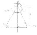
図2に、本装置におけるX線照射系と光照射系のジオメトリ(geometry)を示す。なお、光照射系は反射鏡による光路の折曲げがない状態で示す。光源51は光軸に垂直な方向の辺の長さがaの面光源である。X線焦点11は大きさが無視できる点焦点である。光源51からの光でX線焦点11からのX線と同一のFOVを形成するために、光源51はX線焦点11から光進行の反対方向において距離bの位置に設けられる。 FIG. 2 shows the geometry of the X-ray irradiation system and the light irradiation system in this apparatus. The light irradiation system is shown in a state where the optical path is not bent by the reflecting mirror. The
X線焦点11から検出器9の受光面(FOV平面)までの距離はSIDである。X線焦点11からブレード31が存在する平面(ブレード平面)までの距離はFDである。ブレード31の間隔はBLである。以下、ブレード31の間隔BLをコリメータ開口ともいう。コリメータ開口BLによって形成されるX線の照射野の大きさがFOVである。 The distance from the X-ray
このようなジオメトリの諸元の間には次式の関係がある。 There is a relationship of the following equation between the specifications of such geometry.

ここで、FOVはオペレータによって任意に設定される値であり、BLはそのようなFOVを形成するためのコリメータ開口であり、それ以外の諸元は固定の値である。したがって、FOVが与えられるとコリメータの開口BLは次式によって計算することができる。 Here, FOV is a value arbitrarily set by an operator, BL is a collimator opening for forming such an FOV, and other specifications are fixed values. Therefore, given FOV, the collimator aperture BL can be calculated by the following equation.
オペレータコンソール30は、FOVの設定値が入力されると、その設定値およびジオメトリの諸元を用いて(2)式によりコリメータの開口BLを計算し、ブレード31の間隔がBLとなるように制御する。 When the set value of the FOV is inputted, the operator console 30 calculates the collimator opening BL by the formula (2) using the set value and the geometry, and controls so that the interval between the
光源51の位置は、部品の公差等の影響で正規の位置からずれていることがあり得る。光源51の位置ずれの一例を図3に示す。図3は、光源51の光軸がX線の光軸からずれた場合を示す。このような状態では(1)式の関係が成立しないので、(2)式によってコリメータ開口を制御しても光のFOVはX線のFOVに一致しない。 The position of the
図3のような状態では次式の関係が成立する。 In the state shown in FIG. 3, the relationship of the following equation is established.
ここで、FOVL,FOVSはX線の光軸に関して一方側の半分および他方側の半分であり、BLL,BLSはそのようなFOVをそれぞれ形成するためのコリメータ開口であり、Δは光軸のずれ量であり、それ以外の諸元は固定の値である。したがって、FOV(=FOVL+FOVS)に対応するコリメータの開口BLL,BLSは次式によって与えられる。 Here, FOVL and FOVS are a half on one side and a half on the other side with respect to the optical axis of the X-ray, BLL and BLS are collimator openings for forming such FOVs respectively, and Δ is a deviation of the optical axis. It is a quantity, and other specifications are fixed values. Accordingly, the collimator openings BLL and BLS corresponding to FOV (= FOVL + FOVS) are given by the following equations.
(4)式において光軸のずれ量Δは未知数であるから、このままではコリメータの開口を計算することができない。そこで、次のようにして光軸のずれ量Δの値を特定する。先ず、コリメータの開口を制御してBLL=BLSとなるようにする。この状態でFOVLおよびFOVSの大きさを実測し、それらの差を求める。FOVLとFOVSの差は次式で与えられる。 In equation (4), the amount of deviation Δ of the optical axis is an unknown number, and therefore the aperture of the collimator cannot be calculated as it is. Therefore, the value of the optical axis deviation amount Δ is specified as follows. First, the opening of the collimator is controlled so that BLL = BLS. In this state, the sizes of FOVL and FOVS are actually measured, and the difference between them is obtained. The difference between FOVL and FOVS is given by:
(5)式はΔのみを未知数とする方程式となる。この方程式を解くことにより光軸のずれ量は、 Equation (5) is an equation in which only Δ is an unknown. By solving this equation, the deviation of the optical axis is
として求めることができる。このような計算はコンピュータ302によって行われる。光軸のずれ量は、ジオメトリに関する諸元のうち光軸の位置ずれ量を未知数としそれ以外を既知数とする方程式を解いて求められるので、正しい位置ずれ量を得ることができる。また、既知数のうちコリメータの開口の大きさは設定値であり、FOVの大きさはコリメータによって形成されたFOVの測定値であるので、解の計算が容易である。Can be obtained as Such calculation is performed by the
計算値結果はジオメトリの諸元の一環としてメモリ304に記憶される。このような光軸のずれ量Δの値の特定は、例えば、本装置の稼動サイト(site)へのインストール(install)時に行われる。あるいは、定期または臨時のメンテナンス(maintenance)時に行われる。 The calculated result is stored in the
稼動時には、このように特定された光軸のずれ量Δの値を用いて、(4)式により、FOVの設定値FOVL,FOVSに対応するコリメータの開口BLL,BLSが計算される。このような計算値に基づいてコリメータの開口を制御することにより、光軸のずれに関わらず光照射のFOVをX線照射のFOVに一致させることができる。なお、FOVの設定値はFOVL+FOVSで与えられ、かつ、FOVL=FOVSである。 During operation, collimator openings BLL and BLS corresponding to the FOV set values FOVL and FOVS are calculated by the equation (4) using the value of the optical axis deviation Δ thus identified. By controlling the aperture of the collimator based on such a calculated value, it is possible to make the FOV for light irradiation coincide with the FOV for X-ray irradiation regardless of the deviation of the optical axis. The set value of FOV is given by FOVL + FOVS, and FOVL = FOVS.
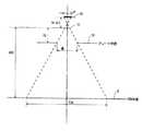
光源51の位置ずれの他の例を図4に示す。図4は、光源51が光軸上でずれた場合を示す。位置ずれの量はΔbである。このような状態では(1)式の関係が成立しないので、(2)式によってコリメータ開口を制御しても光のFOVはX線のFOVに一致しない。 Another example of the positional deviation of the
図4のような状態では次式の関係が成立する。 In the state as shown in FIG. 4, the following relationship is established.
ここで、Δbは光源の位置ずれ量であり、それ以外の諸元は固定の値である。したがって、FOVに対応するコリメータの開口BLは次式によって与えられる。 Here, Δb is the amount of positional deviation of the light source, and the other specifications are fixed values. Therefore, the collimator aperture BL corresponding to the FOV is given by:
(8)式において光源の位置ずれ量Δbは未知数であるから、このままではコリメータの開口を計算することができない。そこで、次のようにして光源の位置ずれ量Δbの値を特定する。先ず、FOVの理想値FOViを定め、FOViに対応するコリメータ開口BLを(2)式によって計算する。これによって In the equation (8), since the positional deviation amount Δb of the light source is unknown, the aperture of the collimator cannot be calculated as it is. Therefore, the value of the positional deviation amount Δb of the light source is specified as follows. First, an ideal value FOVi of FOV is determined, and a collimator opening BL corresponding to FOVi is calculated by equation (2). by this
が得られる。そして、コリメータ開口がBLとなるように制御し、この状態でFOVの大きさを測定して実測値FOVaを得る。このFOVaは光源の位置ずれ量Δbの影響されており、次式で表される。Is obtained. Then, the collimator opening is controlled to be BL, and in this state, the size of the FOV is measured to obtain the actual measurement value FOVa. This FOVa is influenced by the positional deviation amount Δb of the light source and is expressed by the following equation.
(10)式はΔbのみを未知数とする方程式となる。この方程式を解くことにより光源の位置ずれ量は、 Equation (10) is an equation in which only Δb is an unknown. By solving this equation, the amount of misalignment of the light source is
として求めることができる。このような計算はコンピュータ302によって行われる。光源のずれ量は、ジオメトリに関する諸元のうち光源の位置ずれ量を未知数としそれ以外を既知数とする方程式を解いて求められるので、正しい位置ずれ量を得ることができる。また、既知数のうちコリメータの開口の大きさは設定値であり、FOVの大きさはコリメータによって形成されたFOVの測定値であるので、解の計算が容易である。Can be obtained as Such calculation is performed by the
計算値結果はジオメトリの諸元の一環としてメモリ304に記憶される。このような光源の位置ずれ量Δbの値の特定は、例えば、本装置の稼動サイトへのインストール時に行われる。あるいは、定期または臨時のメンテナンス時に行われる。 The calculated result is stored in the
稼動時には、このように特定された光源の位置ずれ量Δbの値を用いて、(8)式により、FOVの設定値に対応するコリメータの開口BLが計算される。このような計算値に基づいてコリメータの開口を制御することにより、光源の位置ずれに関わらず光照射のFOVをX線照射のFOVに一致させることができる。 At the time of operation, the collimator opening BL corresponding to the set value of the FOV is calculated by the equation (8) using the value of the positional deviation amount Δb of the light source thus specified. By controlling the aperture of the collimator based on such a calculated value, it is possible to make the FOV for light irradiation coincide with the FOV for X-ray irradiation regardless of the positional deviation of the light source.
1 X線管
11 X線焦点
3 コリメータボックス
31 ブレード
5 光照射器
51 光源
53 反射鏡
7 撮影対象
9 検出器
30 オペレータコンソール
302 コンピュータ
304 メモリ
32 ディスプレイ1
Claims (3)
Translated fromJapanese前記X線管の焦点を通る軸に対し対称に開口した前記コリメータを通じて照射された前記光源からの光のFOVの実測に基づいて求められた、前記照準用の光の光軸の前記軸と直交する方向における位置ずれを含む前記照準用の光の位置ずれ量を記憶する記憶手段と、
前記照準用の光を照射する際に、前記記憶手段から読み出された前記位置ずれ量が補正されるように前記コリメータの開口を制御する制御手段、
を具備することを特徴とするX線撮影装置。An X-ray imaging apparatus comprising: an X-ray tube; a collimator that forms an X-ray beam that is irradiated from the X-ray tube to the imaging target; and a light source that irradiates the imaging target through the collimator.
Orthogonal to the axis of the optical axis of the sighting light obtained based on the actual measurement of the FOV of the light from the light source irradiated through the collimator opened symmetrically with respect to the axis passing through the focal point of the X-ray tube Storage means for storing a position shift amount of theaiming light including a position shift in a direction to perform;
Control means for controlling the opening of the collimatorso that the amount of positional deviation read from the storage means is corrected when irradiating the aiming light ;
An X-ray imaging apparatus comprising:
ことを特徴とする請求項1に記載のX線撮影装置。The positional deviationamount, Ruasked the positional deviation amount of thelight source of the specifications relating to the geometry of the illumination system of the optical and X-rayand unknowns by solving the equations for the others and known number,
The X-ray imaging apparatus according to claim 1.
ことを特徴とする請求項2に記載のX線撮影装置。Of the known numbers, the size of the aperture of the collimator is a set value, and the size of the FOV is a measured value ofthe FOV formed by the collimator .
The X-ray imaging apparatus according to claim2 .
Applications Claiming Priority (1)
| Application Number | Priority Date | Filing Date | Title |
|---|---|---|---|
| CN2005100818482ACN1888977B (en) | 2005-06-29 | 2005-06-29 | X-ray photographic system |
Publications (2)
| Publication Number | Publication Date |
|---|---|
| JP2007007382A JP2007007382A (en) | 2007-01-18 |
| JP4669791B2true JP4669791B2 (en) | 2011-04-13 |
Family
ID=37545260
Family Applications (1)
| Application Number | Title | Priority Date | Filing Date |
|---|---|---|---|
| JP2006012547AExpired - Fee RelatedJP4669791B2 (en) | 2005-06-29 | 2006-01-20 | X-ray equipment |
Country Status (5)
| Country | Link |
|---|---|
| US (1) | US7413344B2 (en) |
| JP (1) | JP4669791B2 (en) |
| CN (1) | CN1888977B (en) |
| DE (1) | DE102006030127A1 (en) |
| FR (1) | FR2888006B1 (en) |
Families Citing this family (11)
| Publication number | Priority date | Publication date | Assignee | Title |
|---|---|---|---|---|
| JP4946677B2 (en)* | 2007-07-06 | 2012-06-06 | コニカミノルタホールディングス株式会社 | Transmission image photographing system and transmission image photographing method |
| US8908162B2 (en) | 2011-02-24 | 2014-12-09 | Idi Dental, Inc. | System for aligning a collimator and an alignment ring |
| JP2013255642A (en)* | 2012-06-12 | 2013-12-26 | Canon Inc | Radiation generator and radiation imaging system |
| DE102013209322A1 (en)* | 2013-05-21 | 2014-11-27 | Siemens Aktiengesellschaft | Illumination module for an X-ray imaging device, X-ray imaging device with illumination module and associated method |
| US10278654B2 (en) | 2015-02-25 | 2019-05-07 | J. Morita Manufacturing Corporation | Medical X-ray photographing apparatus and X-ray photographing method |
| JP6050905B2 (en)* | 2015-02-25 | 2016-12-21 | 株式会社モリタ製作所 | Medical X-ray imaging apparatus and X-ray imaging method |
| KR101798939B1 (en)* | 2015-09-08 | 2017-11-17 | 삼성전자주식회사 | X-ray image apparatus and control method for the same |
| US10556129B2 (en)* | 2015-10-02 | 2020-02-11 | Varian Medical Systems, Inc. | Systems and methods for treating a skin condition using radiation |
| CN106873302B (en)* | 2016-12-30 | 2018-09-11 | 成都信息工程大学 | A kind of method of detector longitudinal direction automatic tracing bulb focus radial imaging |
| CN108303047A (en)* | 2018-01-02 | 2018-07-20 | 沈阳东软医疗系统有限公司 | A kind of source image away from detection method and device |
| JP7053104B2 (en)* | 2019-02-08 | 2022-04-12 | 富士フイルム株式会社 | Radiation imaging system, medical imaging system, control method, and control program |
Family Cites Families (11)
| Publication number | Priority date | Publication date | Assignee | Title |
|---|---|---|---|---|
| JPS55115001A (en) | 1979-02-27 | 1980-09-04 | Mitsubishi Electric Corp | Aiming mirror plate |
| DE19608862A1 (en)* | 1996-03-07 | 1997-09-11 | Philips Patentverwaltung | X-ray examination device with an X-ray source and an associated aperture unit |
| JP3876942B2 (en)* | 1997-06-13 | 2007-02-07 | 株式会社ワコム | Optical digitizer |
| DE19837512A1 (en)* | 1998-08-19 | 2000-02-24 | Philips Corp Intellectual Pty | X-ray examination device with an aperture unit |
| US6628984B2 (en)* | 2000-04-12 | 2003-09-30 | Pem Technologies, Inc. | Hand held camera with tomographic capability |
| US6478462B2 (en)* | 2001-02-20 | 2002-11-12 | Ge Medical Systems Global Technology Company, Llc | Methodology for determining x-ray to light field decentering on digital radiographic image systems |
| US6739751B2 (en)* | 2001-04-10 | 2004-05-25 | Ge Medical Systems Global Technology Company, Llc | X-ray system alignment method and apparatus |
| JP2003059801A (en)* | 2001-08-14 | 2003-02-28 | Canon Inc | Exposure apparatus and exposure method |
| US6779920B2 (en)* | 2002-02-28 | 2004-08-24 | General Electric Company | X-ray localizer light system |
| US7184136B2 (en) | 2004-04-27 | 2007-02-27 | Santa Barbara Infrared, Inc. | Optical alignment method and system |
| US7366279B2 (en) | 2004-07-29 | 2008-04-29 | General Electric Company | Scatter control system and method for computed tomography |
- 2005
- 2005-06-29CNCN2005100818482Apatent/CN1888977B/ennot_activeExpired - Fee Related
- 2006
- 2006-01-20JPJP2006012547Apatent/JP4669791B2/ennot_activeExpired - Fee Related
- 2006-06-20USUS11/471,296patent/US7413344B2/enactiveActive
- 2006-06-28FRFR0605810Apatent/FR2888006B1/ennot_activeExpired - Fee Related
- 2006-06-28DEDE102006030127Apatent/DE102006030127A1/ennot_activeWithdrawn
Also Published As
| Publication number | Publication date |
|---|---|
| FR2888006A1 (en) | 2007-01-05 |
| US7413344B2 (en) | 2008-08-19 |
| US20070003019A1 (en) | 2007-01-04 |
| CN1888977B (en) | 2010-09-08 |
| FR2888006B1 (en) | 2011-03-04 |
| JP2007007382A (en) | 2007-01-18 |
| CN1888977A (en) | 2007-01-03 |
| DE102006030127A1 (en) | 2007-01-04 |
Similar Documents
| Publication | Publication Date | Title |
|---|---|---|
| JP4669791B2 (en) | X-ray equipment | |
| JP5549595B2 (en) | Radiography equipment | |
| CN108778138B (en) | X-ray collimator and X-ray imaging apparatus using the same | |
| EP2529791B1 (en) | Particle beam therapy system | |
| EP3488783A1 (en) | X-ray phase difference imaging apparatus | |
| JP7164524B2 (en) | X-ray CT device | |
| JP2010240106A (en) | X-ray imaging device, control method therefor and computer program | |
| JP5576620B2 (en) | Control device and control method thereof | |
| JP2007007400A (en) | Computer tomography apparatus and method for computer tomography apparatus | |
| TWI612851B (en) | System for extreme ultraviolet light source, method for aligning an amplified light beam generated from an extreme ultraviolet light system with respect to a target material, and an extreme ultraviolet light system | |
| KR20180025262A (en) | Optical apparatus, machining apparatus, and article manufacturing method, and computer readable storage medium | |
| JPWO2017164251A1 (en) | Extreme ultraviolet light generation apparatus and control method of center of gravity position of extreme ultraviolet light | |
| JP2019066336A (en) | X-ray diffraction measurement apparatus and method | |
| EP3460386A1 (en) | Displacement sensor | |
| JP2017129514A (en) | X-ray diffraction measurement device | |
| JP2004097471A (en) | Radiation generator and radiation irradiation direction calibrator | |
| JPH1026805A (en) | X-ray inspection apparatus having x-ray source and diaphragm unit connected thereto | |
| CN109788928B (en) | Radiation phase difference imaging device | |
| CN105510367A (en) | Pinhole camera adopting X-ray imaging and laser-assisted aiming method | |
| US10918889B2 (en) | LINAC quality control device | |
| KR101689082B1 (en) | X-ray Collimator Systems and Methods using Keystone Correction. | |
| JP6198406B2 (en) | Micro diffraction method and apparatus | |
| CN111246801A (en) | Irradiation target indication | |
| KR20080050930A (en) | X-ray photographing apparatus having a plurality of X-ray detecting sensors | |
| KR102041212B1 (en) | Measurement system for x-ray spectroscopy and imaging |
Legal Events
| Date | Code | Title | Description |
|---|---|---|---|
| A625 | Written request for application examination (by other person) | Free format text:JAPANESE INTERMEDIATE CODE: A625 Effective date:20071228 | |
| A131 | Notification of reasons for refusal | Free format text:JAPANESE INTERMEDIATE CODE: A131 Effective date:20100622 | |
| A601 | Written request for extension of time | Free format text:JAPANESE INTERMEDIATE CODE: A601 Effective date:20100922 | |
| A602 | Written permission of extension of time | Free format text:JAPANESE INTERMEDIATE CODE: A602 Effective date:20100928 | |
| A601 | Written request for extension of time | Free format text:JAPANESE INTERMEDIATE CODE: A601 Effective date:20101022 | |
| A602 | Written permission of extension of time | Free format text:JAPANESE INTERMEDIATE CODE: A602 Effective date:20101027 | |
| A521 | Request for written amendment filed | Free format text:JAPANESE INTERMEDIATE CODE: A523 Effective date:20101122 | |
| TRDD | Decision of grant or rejection written | ||
| A01 | Written decision to grant a patent or to grant a registration (utility model) | Free format text:JAPANESE INTERMEDIATE CODE: A01 Effective date:20101221 | |
| A01 | Written decision to grant a patent or to grant a registration (utility model) | Free format text:JAPANESE INTERMEDIATE CODE: A01 | |
| A61 | First payment of annual fees (during grant procedure) | Free format text:JAPANESE INTERMEDIATE CODE: A61 Effective date:20110117 | |
| FPAY | Renewal fee payment (event date is renewal date of database) | Free format text:PAYMENT UNTIL: 20140121 Year of fee payment:3 | |
| R150 | Certificate of patent or registration of utility model | Free format text:JAPANESE INTERMEDIATE CODE: R150 Ref document number:4669791 Country of ref document:JP Free format text:JAPANESE INTERMEDIATE CODE: R150 | |
| FPAY | Renewal fee payment (event date is renewal date of database) | Free format text:PAYMENT UNTIL: 20140121 Year of fee payment:3 | |
| R250 | Receipt of annual fees | Free format text:JAPANESE INTERMEDIATE CODE: R250 | |
| R250 | Receipt of annual fees | Free format text:JAPANESE INTERMEDIATE CODE: R250 | |
| R250 | Receipt of annual fees | Free format text:JAPANESE INTERMEDIATE CODE: R250 | |
| R250 | Receipt of annual fees | Free format text:JAPANESE INTERMEDIATE CODE: R250 | |
| R250 | Receipt of annual fees | Free format text:JAPANESE INTERMEDIATE CODE: R250 | |
| R250 | Receipt of annual fees | Free format text:JAPANESE INTERMEDIATE CODE: R250 | |
| R250 | Receipt of annual fees | Free format text:JAPANESE INTERMEDIATE CODE: R250 | |
| R250 | Receipt of annual fees | Free format text:JAPANESE INTERMEDIATE CODE: R250 | |
| R250 | Receipt of annual fees | Free format text:JAPANESE INTERMEDIATE CODE: R250 | |
| R250 | Receipt of annual fees | Free format text:JAPANESE INTERMEDIATE CODE: R250 | |
| LAPS | Cancellation because of no payment of annual fees |