JP4669560B1 - Contactless information management / charging system, mobile communication terminal and contactless information / power transmission unit - Google Patents
Contactless information management / charging system, mobile communication terminal and contactless information / power transmission unitDownload PDFInfo
- Publication number
- JP4669560B1 JP4669560B1JP2009281319AJP2009281319AJP4669560B1JP 4669560 B1JP4669560 B1JP 4669560B1JP 2009281319 AJP2009281319 AJP 2009281319AJP 2009281319 AJP2009281319 AJP 2009281319AJP 4669560 B1JP4669560 B1JP 4669560B1
- Authority
- JP
- Japan
- Prior art keywords
- contact
- power supply
- communication terminal
- mobile communication
- contactless
- Prior art date
- Legal status (The legal status is an assumption and is not a legal conclusion. Google has not performed a legal analysis and makes no representation as to the accuracy of the status listed.)
- Expired - Fee Related
Links
- 238000010295mobile communicationMethods0.000titleclaimsabstractdescription46
- 230000005540biological transmissionEffects0.000titleclaimsdescription25
- 238000004891communicationMethods0.000claimsabstractdescription98
- 230000005674electromagnetic inductionEffects0.000claimsabstractdescription16
- 238000000034methodMethods0.000claimsdescription18
- 230000006870functionEffects0.000description18
- 238000010586diagramMethods0.000description6
- 230000004048modificationEffects0.000description6
- 238000012986modificationMethods0.000description6
- 230000008569processEffects0.000description6
- 238000009774resonance methodMethods0.000description6
- 230000015654memoryEffects0.000description5
- 239000003990capacitorSubstances0.000description4
- 230000004044responseEffects0.000description4
- 230000008878couplingEffects0.000description3
- 238000010168coupling processMethods0.000description3
- 238000005859coupling reactionMethods0.000description3
- OKTJSMMVPCPJKN-UHFFFAOYSA-NCarbonChemical compound[C]OKTJSMMVPCPJKN-UHFFFAOYSA-N0.000description2
- RYGMFSIKBFXOCR-UHFFFAOYSA-NCopperChemical compound[Cu]RYGMFSIKBFXOCR-UHFFFAOYSA-N0.000description2
- 230000005856abnormalityEffects0.000description2
- 238000012545processingMethods0.000description2
- HBBGRARXTFLTSG-UHFFFAOYSA-NLithium ionChemical compound[Li+]HBBGRARXTFLTSG-UHFFFAOYSA-N0.000description1
- XAGFODPZIPBFFR-UHFFFAOYSA-NaluminiumChemical compound[Al]XAGFODPZIPBFFR-UHFFFAOYSA-N0.000description1
- 229910052782aluminiumInorganic materials0.000description1
- 238000013459approachMethods0.000description1
- OJIJEKBXJYRIBZ-UHFFFAOYSA-Ncadmium nickelChemical compound[Ni].[Cd]OJIJEKBXJYRIBZ-UHFFFAOYSA-N0.000description1
- 230000008859changeEffects0.000description1
- 229910052802copperInorganic materials0.000description1
- 239000010949copperSubstances0.000description1
- 238000001514detection methodMethods0.000description1
- 239000003792electrolyteSubstances0.000description1
- 238000002474experimental methodMethods0.000description1
- 239000004973liquid crystal related substanceSubstances0.000description1
- 229910001416lithium ionInorganic materials0.000description1
- 230000007257malfunctionEffects0.000description1
- 239000000463materialSubstances0.000description1
- 230000003287optical effectEffects0.000description1
- 229920001690polydopaminePolymers0.000description1
- 239000004065semiconductorSubstances0.000description1
Images


Classifications
- Y—GENERAL TAGGING OF NEW TECHNOLOGICAL DEVELOPMENTS; GENERAL TAGGING OF CROSS-SECTIONAL TECHNOLOGIES SPANNING OVER SEVERAL SECTIONS OF THE IPC; TECHNICAL SUBJECTS COVERED BY FORMER USPC CROSS-REFERENCE ART COLLECTIONS [XRACs] AND DIGESTS
- Y02—TECHNOLOGIES OR APPLICATIONS FOR MITIGATION OR ADAPTATION AGAINST CLIMATE CHANGE
- Y02E—REDUCTION OF GREENHOUSE GAS [GHG] EMISSIONS, RELATED TO ENERGY GENERATION, TRANSMISSION OR DISTRIBUTION
- Y02E60/00—Enabling technologies; Technologies with a potential or indirect contribution to GHG emissions mitigation
- Y02E60/10—Energy storage using batteries
Landscapes
- Charge And Discharge Circuits For Batteries Or The Like (AREA)
- Secondary Cells (AREA)
- Telephone Function (AREA)
Abstract
Translated fromJapaneseDescription
Translated fromJapanese本発明は、非接触式の情報管理・充電システムなどに関する。 The present invention relates to a contactless information management / charging system and the like.
近年、携帯電話やPHS、PDAなどの携帯通信端末においては機能の多様化が飛躍的に進んでいる。例えば利用者の個人情報や電子マネーなどをICチップに記憶し、無線で外部と通信する非接触通信ICモジュールを備えた携帯通信端末が種々提案されている。 In recent years, diversification of functions has been dramatically advanced in mobile communication terminals such as mobile phones, PHS, and PDAs. For example, various portable communication terminals including non-contact communication IC modules that store personal information of users and electronic money in an IC chip and communicate with the outside wirelessly have been proposed.
さらに、非接触通信ICモジュールを備えた携帯通信端末に対して非接触充電モジュー
ルを組み込むことで、非接触通信ICモジュールを利用した情報管理機能と非接触充電機
能の両方を実現するシステム(以下「非接触型の情報管理・充電システム」)が提案され
ている(例えば、非特許文献1参照)。
さらにまた、RFIDリーダとRFIDタグとを含むRFIDシステムにおいて、RFIDリーダライタがRFIDタグにコマンド信号を送信してから所定時間経過した後に、RFIDタグに給電信号を送信することで、情報管理機能と非接触充電機能の両方を実現する方法も提案されている(例えば、特許文献1参照)。Furthermore, a system that realizes both an information management function and a non-contact charging function using a non-contact communication IC module by incorporating a non-contact charging module into a portable communication terminal equipped with the non-contact communication IC module (hereinafter referred to as “ Non-contact type information management / charging system ") has been proposed (for example, see Non-Patent Document 1).
Furthermore, in an RFID system including an RFID reader and an RFID tag, an information management function can be obtained by transmitting a power supply signal to the RFID tag after a predetermined time has elapsed since the RFID reader / writer transmitted a command signal to the RFID tag. A method for realizing both of the contactless charging functions has also been proposed (see, for example, Patent Document 1).
ところで、上記非特許文献1に開示された非接触型の情報管理・充電システムにおいては、非接触充電方式として磁気結合を用いた共鳴方式を採用している。この磁気結合を用いた共鳴方式は、送信側と受信側に、コイルとコンデンサからなるLC回路を作り、両方の回路間で磁場を共鳴させることで、非接触充電を可能とする。磁気結合を用いた共鳴方式は、電磁波や高周波の発生といった問題が生じないものの、共鳴方式を利用した充電システムを構築するためには広いスペースが必要となるうえに、非接触充電を実現するためのアルゴリズムも複雑であり、小型化等が難しいという問題があった。 By the way, in the non-contact information management / charging system disclosed in Non-Patent Document 1, a resonance method using magnetic coupling is adopted as a non-contact charging method. In this resonance method using magnetic coupling, an LC circuit composed of a coil and a capacitor is formed on the transmitting side and the receiving side, and a magnetic field is resonated between both circuits, thereby enabling non-contact charging. Although the resonance method using magnetic coupling does not cause problems such as generation of electromagnetic waves and high frequencies, it requires a large space to build a charging system using the resonance method and realizes non-contact charging. This algorithm is also complicated and there is a problem that it is difficult to reduce the size.
本開示の非接触式の情報管理・充電システムは、非接触通信用アンテナを含む非接触通信ICモジュールと、受電用コイルを含む非接触充電モジュールとを有する携帯通信端末と、前記非接触通信ICモジュールとの間でデータの授受を行うリーダライタと、前記非接触充電モジュールに対して電磁誘導方式により非接触充電を行う電力供給装置とを有し、前記リーダライタの通信面と前記電力供給装置の電力供給面は、所定距離離間した状態で対向配置され、前記携帯通信端末は、前記受電用コイルによって受電された電力を蓄積する、ウルトラキャパシタを含む蓄電装置を有し、当該携帯通信端末の筐体における表示部が形成された面には、前記非接触通信用アンテナが設けられ、前記筐体における他方の面であって前記バッテリが装着された面には、前記受電用コイルが設けられ、前記非接触通信用アンテナと前記受電用コイルの間には電磁シールドとして機能する前記表示部のバックパネルが設けられている。 A non-contact information management / charging system according to the present disclosure includes a non-contact communication IC module including a non-contact communication antenna, a non-contact charging module including a power receiving coil, and the non-contact communication IC. A reader / writer that exchanges data with the module; and a power supply device that performs non-contact charging on the non-contact charging module by an electromagnetic induction method; and a communication surface of the reader / writer and the power supply device The power supply surface of the mobile communication terminal is opposed to each other at a predetermined distance, and the mobile communication terminal has a power storage device including an ultracapacitor that stores the power received by the power receiving coil. The non-contact communication antenna is provided on the surface of the housing where the display unit is formed, and the battery is mounted on the other surface of the housing. The The surface, the power receiving coil is provided, the back panel of the display unit functioning as an electromagnetic shield between said non-contact communication antenna the power receiving coil is provided.
本開示の非接触方式の情報・電力伝送ユニットは、非接触通信ICモジュールとの間でデータの授受を行うリーダライタと、非接触充電モジュールに対して電磁誘導方式により非接触充電を行う電力供給装置とを有し、前記リーダライタの通信面と前記電力供給装置の通信面は、所定距離離間した状態で対向配置されている。 The contactless information / power transmission unit of the present disclosure includes a reader / writer that exchanges data with a contactless communication IC module, and a power supply that performs contactless charging to the contactless charging module by electromagnetic induction. And the communication surface of the reader / writer and the communication surface of the power supply device are arranged to face each other with a predetermined distance therebetween.
本開示の携帯通信端末は、非接触通信用アンテナを含む非接触通信ICモジュールと、電磁誘導方式による非接触充電を行ための受電用コイルを含む非接触充電モジュールとを有する携帯通信端末であって、当該携帯通信端末における筐体の一方の面には、前記非接触通信用アンテナが設けられ、前記筐体の他方の面には、前記受電用コイルが設けられ、前記非接触通信用アンテナと前記受電用コイルの間には電磁シールドが設けられている。 The mobile communication terminal of the present disclosure is a mobile communication terminal having a contactless communication IC module including a contactless communication antenna and a contactless charging module including a power receiving coil for performing contactless charging by an electromagnetic induction method. The non-contact communication antenna is provided on one surface of the housing of the mobile communication terminal, and the power receiving coil is provided on the other surface of the housing. And an electromagnetic shield is provided between the power receiving coil.
A.本実施形態
(1)実施形態の構成
図1は、本実施形態に係る非接触式の情報管理・充電システム100の構成を示す図である。
非接触式の情報管理・充電システム100は、非接触通信ICモジュールと非接触充電モジュールを備えた携帯通信端末400と、リーダライタ500と無線電力供給ユニット600を備えた情報・電力伝送ユニット700とを備えて構成される。A. Embodiment (1) Configuration of Embodiment FIG. 1 is a diagram showing a configuration of a contactless information management /
A contactless information management /
本実施形態に係る非接触式の情報管理・充電システム100は、非接触充電方式として従来例に示す共鳴方式ではなく、電磁誘導方式を採用する。電磁誘導方式を採用した場合には、共鳴方式を採用した場合よりもアルゴリズムの簡易化、充電システムを小型化することができるが、非接触充電の際に電磁波が発生し、この電磁波が原因で電子機器内にノイズを発生させて誤動作等を誘発するという電磁干渉の問題を生ずる。本実施形態に係る非接触式の情報管理・充電システム100は、以下に示す構成を採用することにより、電磁誘導方式を採用することで生ずる電磁干渉の問題を解消する。 The contactless information management /
1−1.携帯通信端末400
図2は、携帯通信端末400の構成を示すブロック図であり、図3は、携帯通信端末400の要部構成を示す断面図である。
携帯通信端末400は、制御部410と、表示部420と、通信部430と、非接触通信ICモジュール200と、非接触充電モジュール300とを備えて構成される。1-1.
2 is a block diagram showing the configuration of the
The
携帯通信端末400は、例えば携帯電話やPHS(Personal Handyphone System)、PDA(Personal Digital Assistant)などであり、非接触通信ICモジュール200を利用したIDタグによる情報管理機能と、非接触充電モジュール300を利用した非接触充電機能を実現する。なお、携帯通信端末400はこれらに限らず、例えばノート型パソコンや携帯型デジタルオーディオプレーヤなど、充電可能な蓄電装置(例えばウルトラキャパシタや二次電池など)を備えたあらゆる電子機器に適用可能である。また、本実施形態では折り畳み式の携帯通信端末を想定するが(図3参照)、例えばスライド式など、あらゆるタイプの携帯通信端末に適用可能である。なお、ウルトラキャパシタとは、電気二重層コンデンサは活性炭と電解液の界面に発生する電気二重層を動作原理として利用した電気二重層コンデンサ(Electric double-layer capacitor)を意味する。 The
制御部410は、CPU、ROM、RAMなどにより構成され、従来と同様、CPUがROMなどに格納された各種制御プログラムを実行することにより、携帯通信端末400の各部を中枢的に制御する。 The
表示部420は、例えばLCD(Liquid Crystal Display)などからなり、図3に示すように携帯通信端末400における本体上部401aの前面に設けられている。表示部420は、従来と同様、各種制御プログラムの実行結果などを表示する。 The
通信部430は、移動体通信アンテナや各通信インタフェースなどを備え、従来と同様
、携帯通信端末間でのデータ(音声データや文字データなど)の授受を行う。なお、通信
部430は、例えば近距離無線通信(例えばBluetooth(登録商標))や赤外線通信など、その他の通信機能を備えていても良い。The
操作部440は、従来と同様、例えば数字キーや文字キーなどの操作ボタンなどから構成され、図3に示すように携帯通信端末400における本体下部401bの前面に設けられている。 The
<非接触通信ICモジュール200>
非接触通信ICモジュール200は、制御部410による制御のもと、リーダライタ500との間で無線通信によりデータの授受を行うものであり、チップ用二次電池210と、ICチップ220と、非接触通信用アンテナコイル230とを有している(図2参照)。<Non-contact
The non-contact
非接触通信ICモジュール200は、従来と同様、リーダライタ500から受信する数MHz〜数十MHz程度(例えば13.56MHz)の低い周波数帯域の電波を利用して、ICチップ220に格納されている各情報をリーダライタ500に送信したり、リーダライタ500からの指示に応じてICチップ220に格納されている各情報の変更等を行う。 The non-contact
ICチップ220は、非接触通信用アンテナ230とともにICタグを構成しており、従来と同様、CPUや各種メモリ(RAM、EEPROMなど)を備え、識別子としてのユニークなタグIDや、タグIDに関連する情報(以下、ID関連情報と総称)などをメモリに格納するとともに、リーダライタ500からの指示に従ってメモリに格納されているID関連情報の変更等を行う。 The
非接触通信用アンテナコイル230は、リーダライタ500との間で無線通信を行うためのアンテナであり、従来と同様、例えば細い銅線をループ上に数回〜数百回巻回したものを利用することができる。この非接触通信用アンテナコイル230は、図3に示すように携帯通信端末400の表面(または携帯通信端末400表面近傍)に設けられている。なお、特許請求の範囲では、表面また表面近傍を含む概念として「面側」と総称する。この非接触通信用アンテナコイル230と、無線電力供給ユニット600から電力供給を受けるための受電用コイル320との間には、電磁干渉を防止するための電磁シールド750が設けられている(詳細は後述)。 The non-contact
チップ用二次電池210は、ICチップ220を駆動するための電源を供給する手段であり、従来と同様、例えば有機ラジカル電池などを利用することができる。なお、本実施形態では、内蔵された電源(ここではチップ用二次電池210)を利用してICチップ220を駆動するアクティブ型のICチップを例示したが、電源を内蔵せずにリーダライタ500から発信される電波を電力に変換してICチップ220を駆動するパッシブ型のICチップにも適用可能である。 The chip
<非接触充電モジュール300>
非接触充電モジュール300は、制御部410による制御のもと、電磁誘導方式を利用して無線電力供給ユニット600から与えられる電力をバッテリ310に充電するものであり、バッテリ310と、受電用コイル320と、充電制御回路330とを有している。<
The
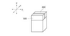
バッテリ310は、携帯通信端末用の蓄電装置であり、例えばウルトラキャパシタやスーパーキャパシタなどの電気二重コンデンサなどよって構成されている。もちろん、電気二重コンデンサに限らず、現在広く利用されているリチウムイオン二次電池やニッケル・カドミニウム電池などによってバッテリ310を構成しても良い。バッテリ310は、図3に示すように携帯通信端末400における本体下部401bの背面に着脱自在に取り付けられている。 The
受電用コイル320は、従来と同様、無線電力供給ユニット600の送電用コイル(図示略)との間で生じる電磁誘導により、送電用コイルから供給される電力を受け取る手段である。
受電用コイル320は、図3に示すように携帯通信端末400の背面(または携帯通信端末400背面近傍)に設けられている。なお、特許請求の範囲では、背面また背面近傍を含む概念として「面側」と総称する。The
As shown in FIG. 3, the
受電用コイル320は、上述したように電磁シールド750を挟んで非接触通信用アンテナコイル230に対向するように配置されている(図3参照)。電磁シールド750は、例えば銅やアルミニウムなどの材料によって構成されている。この電波シールド750の存在により、非接触充電時に発生し得る電磁干渉を未然に防止することが可能となる(詳細は後述)。なお、電磁シールド750を設けずとも、図3に示す表示部430のバックパネルが電磁シールド750の役割を果たす場合には、このバックパネルを挟んで非接触通信用アンテナコイル230と受電用コイル320を配置しても良い。 As described above, the
充電制御回路330は、無線電力供給ユニット600から供給される電力をバッテリ310に蓄積する充電機能や、バッテリ310の過充電を防止するバッテリ保護機能などを実現する。 The charging
1−2.情報・電力伝送ユニット700
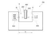
図4は、情報・電力伝送ユニット700の要部構成を示す図である。
図1に示すように、情報・電力伝送ユニット700は、携帯通信端末400の非接触通信ICモジュール200に格納されている情報の読み取り・書き込み等を行うリーダライタ500と、非接触充電モジュール300に対して電磁誘導方式を利用して電力供給を行う無線電力供給ユニット600とを備えて構成される。1-2. Information and
FIG. 4 is a diagram illustrating a main configuration of the information /
As shown in FIG. 1, the information /
リーダライタ500は、携帯通信端末400に搭載された非接触通信ICモジュール200との無線通信により、ICチップ220に格納されたID関連情報等の読み込みやID関連情報の変更指示などを行う。 The reader /
無線電力供給ユニット(電力供給装置)600は、送電用コイルやDC−ACコンバータなどを備え、携帯通信端末400に搭載された非接触充電モジュール300の受電用コイル320に対して、電磁誘導の原理を利用して交流電圧にて電力を供給する。 The wireless power supply unit (power supply device) 600 includes a power transmission coil, a DC-AC converter, and the like, and the principle of electromagnetic induction with respect to the
図1及び図4に示すように、リーダライタ500と無線電力供給ユニット600は、所定の距離Wだけ隔てて配置されている。詳述すると、リーダライタ500の通信面f1と無線電力供給ユニット600の電力供給面f2は所定の距離Wだけ離れており(図4参照)、リーダライタ500と無線電力供給ユニット600との間には幅Wの凹溝Sが形成されている。 As shown in FIGS. 1 and 4, the reader /
携帯通信端末400を利用するユーザは、図4に示すように携帯通信端末400を情報・電力伝送ユニット700の凹溝Sに進入させ、非接触通信ICモジュール200が設けられた本体上部401aの前面とリーダライタ500の通信面f1、非接触充電モジュール300が設けられた本体上部401aの背面と無線電力供給ユニット600の電力供給面f2をそれぞれ対応させる。かかる操作を契機としてリーダライタ500と非接触通信ICモジュール200の間のデータ通信、非接触充電モジュール300と無線電力供給ユニット600から非接触充電モジュール300への電力供給が開始される。なお、凹溝Sの幅Wは、理論的(あるいは実験)により求まるリーダライタ500と非接触通信ICモジュール200との間でデータ通信が可能な距離(以下、通信可能距離)や、無線電力供給ユニット600から非接触充電モジュール300への電力供給が可能な距離(以下、供給可能距離)などを考慮して決定すれば良い。 As shown in FIG. 4, the user using the
(2)実施形態の動作
図5は、非接触式の情報管理・充電システム100の動作を説明するための図である。
携帯通信端末400を所持するユーザは、情報・電力伝送ユニット700の入口Enにさしかかると、携帯通信端末400を情報・電力伝送ユニット700の凹溝Sに進入させ、非接触通信ICモジュール200が設けられた前面(図3参照)とリーダライタ500の通信面f1、非接触充電モジュール300が設けられた背面(図3参照)と無線電力供給ユニット600の電力供給面f2をそれぞれ対応させる(図5のA参照)。かかる操作をトリガとして、以下に示す情報管理機能に関する動作、非接触充電機能に関する動作が略同時に開始される。(2) Operation of Embodiment FIG. 5 is a diagram for explaining the operation of the contactless information management /
When the user carrying the
2−1.情報管理機能に関する動作
図6は、非接触式の情報管理・充電システム100の動作を示すシーケンス図である。
リーダライタ500は、携帯通信端末400の非接触通信ICモジュール200から送信される信号などに基づいて、自身の通信エリア内にICチップ220が存在することを確認すると(ステップS10;YES)、13.56MHz程度の低い周波数帯域の電波を利用して、タグID関連情報の取得要求コマンドを非接触通信ICモジュール200に送信する(ステップS20)。2-1. Operation Regarding Information Management Function FIG. 6 is a sequence diagram showing the operation of the non-contact information management /
When the reader /
非接触通信ICモジュール200のICチップ220は、リーダライタ500からタグID関連情報の取得要求コマンドを受信すると、このコマンドに従ってメモリからタグID関連情報を読み取る(ステップS30)。そして、ICチップ220は、非接触通信用アンテナコイル230を介して、読み取ったタグID関連情報をリーダライタ500に返信する(ステップS40)。なお、本実施形態ではアクティブ型のICチップ220を想定しているため、ICチップ220はチップ用二次電池210を電源として駆動される。 When receiving the tag ID related information acquisition request command from the reader /
一方、リーダライタ500は、タイマなどを利用して、タグID関連情報の取得要求コマンドを送信してから、このコマンドに応じてタグID関連情報を受信するまでの時間(以下、応答時間)Trを計測している。リーダライタ500は、計測した応答時間Trがメモリに設定された閾値時間Tth未満である場合には(ステップS50;YES)、正常にタグID関連情報を受信したと判断し、例えばタグID関連情報からユーザの個人情報を取得・管理する等の情報管理処理を実行する。一方、計測した応答時間Trが閾値時間Tthを超えている場合には(ステップS50;NO)、タグID関連情報を受信するまでの間に何らかの異常が生じたと判断し、異常時の処理(例えばリトライや、正常に受信できなかった旨の報知など)を行い、処理を終了する。 On the other hand, the reader /
2−2.非接触充電機能に関する動作
無線電力供給ユニット600は、送電用コイルと非接触充電モジュール300の受電用コイル320との間に生じる電磁誘導を利用して、送電用コイルから受電用コイル320への電力供給を開始する(ステップS110)。2-2. Operation Related to Non-Contact Charging Function The wireless
非接触充電モジュール300の充電制御回路330は、無線電力供給ユニット600から受け取った電力をバッテリ310に蓄積し、充電を開始する(ステップS120)。 The charging
非接触充電モジュール300は、ステップS130に進むと、無線電力供給ユニット600からの電力供給が終了したか否かを判断する(ステップS130)。例えば、図5のCに示すように、携帯通信端末400が凹溝Sの出口Exから出ており、無線電力供給ユニット600から電力供給を受けていない場合には、無線電力供給ユニット600による電力供給は終了したと判断し(ステップS130;YES)、処理を終了する。これに対し、例えば、図5のBに示すように、携帯通信端末400が凹溝Sの中にあり、未だ無線電力供給ユニット600から電力供給を受けている場合には、電力供給は終了していないと判断し(ステップ130;NO)、ステップS140に進む。 When the
非接触充電モジュール300の充電制御回路(検知手段、判断手段)330は、バッテリ310の充電状態を検知するとともに、このまま無線電力供給ユニット600から電力供給を受けた場合に過充電のおそれがあるか否かを判断する(ステップS140)。充電制御回路330は、例えばバッテリ310の蓄電容量が設定された閾値を超えていない場合には、過充電のおそれなしと判断する一方、バッテリ310の蓄電容量が設定された閾値を超えている場合には、過充電のおそれありと判断する。充電制御回路330は、過充電のおそれなしと判断すると(ステップS140;NO)、ステップS120に戻り、バッテリ310への充電を継続する。 The charge control circuit (detection means, determination means) 330 of the
一方、充電制御回路330は、過充電のおそれありと判断すると(ステップS140;YES)、非接触受電モジュール300は、バッテリ310への充電を禁止し、無線電力供給ユニット600に対して電力供給を終了すべき指示(以下、電力供給終了指示)を送信し(ステップS150)、処理を終了する。無線電力供給ユニット600は、非接触充電モジュール300から電力供給終了指示を受け取ると、携帯通信端末400に対する電磁誘導方式による電力供給を終了する(ステップS160)。 On the other hand, when the charging
なお、上記例では、凹溝Sの入口Enから出口Exまでの長さLについて特に言及しなかったが、例えば無線電力供給ユニット600の電力供給能力や、無線電力供給ユニット600から非接触充電モジュール300へ供給する電力量などに応じて長さLを決定すれば良い。例えば、携帯通信端末400が凹溝Sの入口Enから出口Exを通過するまでの間に、バッテリ310の充電が80%程度完了できるように長さLを設定すれば良い。 In the above example, the length L from the inlet En to the outlet Ex of the concave groove S is not particularly mentioned. However, for example, the power supply capability of the wireless
B.変形例
(1)上述した本実施形態では、情報管理機能の動作と非接触充電機能の動作の関連性について特に言及しなかったが、次のように関連性を持たせても良い。例えばリーダライタ500によって読み取られたID関連情報に基づいて登録ユーザ認証などを行い、該登録ユーザ認証に成功した場合にのみ、無線電力供給ユニット600から非接触充電モジュール300への電力供給を開始する。かかる構成によれば、登録ユーザに対する非接触の電力供給を簡易に実現することが可能となる。B. Modification (1) In the above-described embodiment, the relevance between the operation of the information management function and the operation of the non-contact charging function is not particularly mentioned, but the relevance may be given as follows. For example, registered user authentication is performed based on ID-related information read by the reader /
(2)上述した本実施形態では、携帯通信端末400の本体上部401aに、非接触通信ICモジュール200と非接触充電モジュール300を搭載した場合について説明したが(図3参照)、例えば図7に示すように、非接触通信ICモジュール200を携帯通信端末400の本体下部401bの前面側に内蔵し、本体下部401bの背面側に電磁シールド750を設けても良い。この場合、非接触充電モジュール300は、例えば携帯通信端末400の本体上部401aの背面側に内蔵すれば良い。このように、携帯通信端末400における一方の面側に非接触通信用アンテナ200を設け、この非接触通信用アンテナ200と他方の面側(本体上部401aの背面側)の間に電磁シールド750を設けても良い。(2) In the above-described embodiment, the case where the contactless
(2)上述した本実施形態では、図8Aに示すようにリーダライタ500と無線電力供給ユニット600を横方向(図8Aに示すY軸方向)に並べた構成を例示したが、例えば図8Bに示すようにリーダライタ500と無線電力供給ユニット600を縦方向(図8Bに示すZ方向)に並べた構成を採用しても良い。なお、リーダライタ500と無線電力供給ユニット600の位置を入れ換えても良い。(2) In the present embodiment described above, the configuration in which the reader /
(3)上述した本実施形態では、リーダライタ500と無線電力供給ユニット600は同一の長さLを有していたが(図5参照)、例えば図9に示すようにリーダライタ500の長さL1を、無線電力供給ユニット600の長さL2よりも短く設定しても良い。リーダライタ500の長さL1については、例えば非接触通信ICモジュール200とのデータ通信が完了し得る長さ(最低長さ)に設定すれば良い。なお、最低長さは予め実験などによって求めておけば良い。(3) In the present embodiment described above, the reader /
また、リーダライタ500と無線電力供給ユニット600を複数用意し、図10に示すように複数のリーダライタ500と無線電力供給ユニット600それぞれ千鳥状に配置した情報・電力伝送ユニット700を形成しても良い。 Alternatively, a plurality of reader /
かかる構成によれば、ユーザは、携帯通信端末400の本体部401aの前面(または背面)を、リーダライタ500または無線電力供給ユニット600の通信面のいずれに向けるかを考える必要がないため、本実施形態に係る情報・電力伝送ユニット00に比べて、ユーザはより簡易にシステムを利用することができる。 According to such a configuration, the user does not need to consider whether the front surface (or the back surface) of the
また、本実施形態において示した各処理のステップは処理内容に矛盾を生じない範囲で任意に順番を変更して又は並列に実行することができる。さらに本明細書等において、手段とは、単に物理的手段を意味するものではなく、その手段が有する機能をソフトウェアによって実現する場合も含む。さらにまた、1つの手段が有する機能が2つ以上の物理的手段により実現されても、2つ以上の手段の機能が1つの物理的手段により実現されてもよい。また、本発明に係るソフトウェアは、CD−ROMやDVD−ROM等の光学ディスク、磁気ディスク、半導体メモリなどの各種の記録媒体を通じて、又は通信ネットワークなどを介してダウンロードすることにより、コンピュータにインストール又はロードすることができる。 In addition, the steps of the processes shown in the present embodiment can be executed in any order or in parallel within a range where no contradiction occurs in the process contents. Furthermore, in this specification and the like, the term “means” does not simply mean a physical means, but includes a case where the functions of the means are realized by software. Furthermore, the function of one means may be realized by two or more physical means, or the functions of two or more means may be realized by one physical means. The software according to the present invention can be installed on a computer by downloading it through various recording media such as an optical disk such as a CD-ROM or DVD-ROM, a magnetic disk, or a semiconductor memory, or via a communication network. Can be loaded.
100…非接触式の情報管理・充電システム、200…非接触通信ICモジュール、210…チップ用二次電池、220…ICチップ、230…非接触通信用アンテナコイル、300…非接触充電モジュール、310…バッテリ、320…受電用コイル、330…充電制御回路、400…携帯通信端末、410…制御部、420…表示部、430…通信部、500…リーダライタ、600…無線電力供給ユニット、700…情報・電力伝送ユニット、750…電磁シールド。DESCRIPTION OF
Claims (4)
Translated fromJapanese充電モジュールとを有する携帯通信端末と、
前記非接触通信ICモジュールとの間でデータの授受を行うリーダライタと、
前記非接触充電モジュールに対して電磁誘導方式により非接触充電を行う電力供給装置
とを有し、
前記リーダライタの通信面と前記電力供給装置の電力供給面は、所定距離離間した状態
で対向配置され、
前記携帯通信端末の非接触充電モジュールは、前記受電用コイルによって受電された電
力を蓄積する、ウルトラキャパシタを含む蓄電装置を有し、
当該携帯通信端末の筐体における表示部が形成された面側には、前記非接触通信用アン
テナが設けられ、前記筐体における他方の面側であって前記蓄電装置が装着された面側に
は、前記受電用コイルが設けられ、前記非接触通信用アンテナと前記受電用コイルの間に
は電磁シールドとして機能する前記表示部のバックパネルが設けられている、非接触式の
情報管理・充電システム。A portable communication terminal having a contactless communication IC module including a contactless communication antenna and a contactless charging module including a power receiving coil;
A reader / writer that exchanges data with the non-contact communication IC module;
A power supply device that performs non-contact charging by electromagnetic induction on the non-contact charging module;
The communication surface of the reader / writer and the power supply surface of the power supply device are arranged to face each other with a predetermined distance therebetween,
The non-contact charging module of the mobile communication terminal has a power storage device including an ultracapacitor that accumulates electric power received by the power receiving coil,
The contactless communication antenna is provided on the surface side of the casing of the mobile communication terminal on which the display unit is formed, and is on the other surface side of the casing where the power storage device is attached. Is a non-contact information management / charging system in which the power receiving coil is provided and a back panel of the display unit functioning as an electromagnetic shield is provided between the non-contact communication antenna and the power receiving coil. system.
充電を行ための受電用コイルを含む非接触充電モジュールとを有する携帯通信端末であっ
て、
当該携帯通信端末における筐体の対向する二つの面のうち一方の面側には、前記非接触
通信用アンテナが設けられ、前記筐体の他方の面側には、前記受電用コイルが設けられ、
前記非接触通信用アンテナと前記他方の面側の間には電磁シールドが設けられており、
前記非接触通信用アンテナが設けられた前記一方の面側は、表示部が形成された面側で
あり、
前記電磁シールドは、前記表示部のバックパネルである携帯通信端末。A mobile communication terminal having a contactless communication IC module including a contactless communication antenna and a contactless charging module including a power receiving coil for performing contactless charging by an electromagnetic induction method,
The non-contact communication antenna is provided on one of the two opposing surfaces of the housing of the mobile communication terminal, and the power receiving coil is provided on the other surface of the housing. ,
An electromagnetic shield is provided between the non-contact communication antenna and the other surface side,
The one surface side provided with the non-contact communication antenna is a surface side on which a display unit is formed.
Yes,
The electromagnetic shield is a mobile communication terminalthat is a back panel of the display unit .
ルトラキャパシタを含む蓄電装置を有し、
前記受電用コイルが設けられた他方の面側は、前記蓄電装置が装着された面側である、
請求項2に記載の携帯通信端末。The non-contact charging module has a power storage device including an ultracapacitor that stores the power received by the power receiving coil,
The other surface side provided with the power receiving coil is a surface side on which the power storage device is mounted.
The mobile communication terminal according to claim 2.
ジュールに対して電磁誘導方式により非接触充電を行う電力供給装置とを有し、
前記リーダライタの通信面と前記電力供給装置の電力供給面は、所定距離離間した状態
で対向配置されている、非接触式の情報・電力伝送ユニット。A reader / writer that exchanges data with the non-contact communication IC module, and a power supply device that performs non-contact charging by electromagnetic induction on the non-contact charging module,
A non-contact type information / power transmission unit in which a communication surface of the reader / writer and a power supply surface of the power supply device are arranged to face each other with a predetermined distance therebetween.
Priority Applications (1)
| Application Number | Priority Date | Filing Date | Title |
|---|---|---|---|
| JP2009281319AJP4669560B1 (en) | 2009-12-11 | 2009-12-11 | Contactless information management / charging system, mobile communication terminal and contactless information / power transmission unit |
Applications Claiming Priority (1)
| Application Number | Priority Date | Filing Date | Title |
|---|---|---|---|
| JP2009281319AJP4669560B1 (en) | 2009-12-11 | 2009-12-11 | Contactless information management / charging system, mobile communication terminal and contactless information / power transmission unit |
Publications (2)
| Publication Number | Publication Date |
|---|---|
| JP4669560B1true JP4669560B1 (en) | 2011-04-13 |
| JP2011123708A JP2011123708A (en) | 2011-06-23 |
Family
ID=44021719
Family Applications (1)
| Application Number | Title | Priority Date | Filing Date |
|---|---|---|---|
| JP2009281319AExpired - Fee RelatedJP4669560B1 (en) | 2009-12-11 | 2009-12-11 | Contactless information management / charging system, mobile communication terminal and contactless information / power transmission unit |
Country Status (1)
| Country | Link |
|---|---|
| JP (1) | JP4669560B1 (en) |
Cited By (8)
| Publication number | Priority date | Publication date | Assignee | Title |
|---|---|---|---|---|
| JPWO2012172812A1 (en)* | 2011-06-14 | 2015-02-23 | パナソニック株式会社 | Communication device |
| US9607757B2 (en) | 2011-11-02 | 2017-03-28 | Panasonic Corporation | Non-contact wireless communication coil, transmission coil, and portable wireless terminal |
| US9667086B2 (en) | 2012-06-28 | 2017-05-30 | Panasonic Intellectual Property Management Co., Ltd. | Mobile terminal |
| US9735606B2 (en) | 2012-06-28 | 2017-08-15 | Panasonic Intellectual Property Management Co., Ltd. | Mobile terminal including charging coil and wireless communication coil, wireless charging module including charging coil and wireless communication coil |
| US9935481B2 (en) | 2012-02-17 | 2018-04-03 | Panasonic Intellectual Property Management Co., Ltd. | Mobile terminal including wireless charging module and battery pack |
| US10204734B2 (en) | 2011-11-02 | 2019-02-12 | Panasonic Corporation | Electronic device including non-contact charging module and near field communication antenna |
| US10218222B2 (en) | 2011-01-26 | 2019-02-26 | Panasonic Intellectual Property Management Co., Ltd. | Non-contact charging module having a wireless charging coil and a magnetic sheet |
| CN111937504A (en)* | 2018-04-09 | 2020-11-13 | 三星电子株式会社 | Electronic device equipped with flexible display and wireless charging method using the same |
Families Citing this family (5)
| Publication number | Priority date | Publication date | Assignee | Title |
|---|---|---|---|---|
| JP6071301B2 (en)* | 2011-07-29 | 2017-02-01 | アールエフ・アンテナ株式会社 | Non-contact information communication system |
| JP6045141B2 (en)* | 2011-12-05 | 2016-12-14 | キヤノン株式会社 | Electronic device and program |
| US9166286B2 (en) | 2013-03-29 | 2015-10-20 | Panasonic Intellectual Property Management Co., Ltd. | Communication device |
| JP6600810B2 (en)* | 2015-11-24 | 2019-11-06 | パナソニックIpマネジメント株式会社 | Communication equipment with non-contact charging function |
| EP3798855A4 (en) | 2018-05-21 | 2021-08-11 | FeliCa Networks, Inc. | PORTABLE TERMINAL AND METHOD FOR MANAGING IC CHIP |
Family Cites Families (14)
| Publication number | Priority date | Publication date | Assignee | Title |
|---|---|---|---|---|
| JPH08241386A (en)* | 1995-03-03 | 1996-09-17 | Hitachi Maxell Ltd | Contactless memory card and electromagnetic coupling device mountable on the same |
| JPH09190938A (en)* | 1996-01-09 | 1997-07-22 | Tdk Corp | Non-contact type battery charger |
| JPH10282896A (en)* | 1997-04-07 | 1998-10-23 | Mitsubishi Electric Corp | Display device |
| JP4546852B2 (en)* | 2005-02-28 | 2010-09-22 | 三菱電機株式会社 | Verification system |
| CN101802942A (en)* | 2007-01-29 | 2010-08-11 | 普迈公司 | Pinless power coupling |
| EP3975372B1 (en)* | 2007-03-22 | 2024-01-31 | Powermat Technologies Ltd. | Efficiency monitor for inductive power transmission |
| JPWO2009031639A1 (en)* | 2007-09-06 | 2010-12-16 | 昭和電工株式会社 | Non-contact rechargeable power storage device |
| KR20100061845A (en)* | 2007-09-25 | 2010-06-09 | 파우워매트 엘티디. | Adjustable inductive power transmission platform |
| EP2400629A3 (en)* | 2007-10-09 | 2012-05-02 | Powermat Technologies Ltd. | Chargeable inductive power outlet |
| KR101524892B1 (en)* | 2007-10-09 | 2015-06-01 | 파워매트 테크놀로지스 엘티디. | Inductive power providing system having moving outlets |
| JP2009135843A (en)* | 2007-11-30 | 2009-06-18 | Mie Denshi Kk | display |
| CN102084442B (en)* | 2008-03-17 | 2013-12-04 | 鲍尔马特技术有限公司 | Inductive transmission system |
| JP4698702B2 (en)* | 2008-05-22 | 2011-06-08 | 三菱電機株式会社 | Electronics |
| AU2009254785A1 (en)* | 2008-06-02 | 2009-12-10 | Powermat Technologies Ltd. | Appliance mounted power outlets |
- 2009
- 2009-12-11JPJP2009281319Apatent/JP4669560B1/ennot_activeExpired - Fee Related
Cited By (25)
| Publication number | Priority date | Publication date | Assignee | Title |
|---|---|---|---|---|
| US10218222B2 (en) | 2011-01-26 | 2019-02-26 | Panasonic Intellectual Property Management Co., Ltd. | Non-contact charging module having a wireless charging coil and a magnetic sheet |
| JPWO2012172812A1 (en)* | 2011-06-14 | 2015-02-23 | パナソニック株式会社 | Communication device |
| US10468913B2 (en) | 2011-06-14 | 2019-11-05 | Sovereign Peak Ventures, Llc | Electronic device including non-contact charging module |
| US10044225B2 (en) | 2011-06-14 | 2018-08-07 | Panasonic Corporation | Electronic device including non-contact charging module |
| US10003219B1 (en) | 2011-06-14 | 2018-06-19 | Panasonic Corporation | Electronic device including non-contact charging module |
| US9954396B2 (en) | 2011-06-14 | 2018-04-24 | Panasonic Corporation | Electronic device including non-contact charging module |
| US9941048B2 (en) | 2011-11-02 | 2018-04-10 | Panasonic Corporation | Non-contact wireless communication coil, transmission coil, and portable wireless terminal |
| US10204734B2 (en) | 2011-11-02 | 2019-02-12 | Panasonic Corporation | Electronic device including non-contact charging module and near field communication antenna |
| US9607757B2 (en) | 2011-11-02 | 2017-03-28 | Panasonic Corporation | Non-contact wireless communication coil, transmission coil, and portable wireless terminal |
| US9634515B2 (en) | 2011-11-02 | 2017-04-25 | Panasonic Corporation | Non-contact wireless communication coil, transmission coil, and portable wireless terminal |
| US10574082B2 (en) | 2012-02-17 | 2020-02-25 | Sovereign Peak Ventures, Llc | Electronic device including non-contact charging module and battery |
| US9991735B1 (en) | 2012-02-17 | 2018-06-05 | Panasonic Intellectual Property Management Co., Ltd. | Electronic device including non-contact charging module and battery |
| US12040562B2 (en) | 2012-02-17 | 2024-07-16 | Sovereign Peak Ventures, Llc | Electronic device including non-contact charging module and battery |
| US11070075B2 (en) | 2012-02-17 | 2021-07-20 | Sovereign Peak Ventures, Llc | Electronic device including non-contact charging module and battery |
| US9997952B2 (en) | 2012-02-17 | 2018-06-12 | Panasonic Intellectual Property Management Co., Ltd. | Wireless charging module and mobile terminal including the same |
| US9935481B2 (en) | 2012-02-17 | 2018-04-03 | Panasonic Intellectual Property Management Co., Ltd. | Mobile terminal including wireless charging module and battery pack |
| US10020673B2 (en) | 2012-02-17 | 2018-07-10 | Panasonic Intellectual Property Management Co., Ltd. | Electronic device including non-contact charging module and battery |
| US10291069B2 (en) | 2012-06-28 | 2019-05-14 | Panasonic Intellectual Property Management Co., Ltd. | Mobile terminal and chargeable communication module |
| US10574090B2 (en) | 2012-06-28 | 2020-02-25 | Sovereign Peak Ventures, Llc | Mobile terminal including wireless charging coil and magnetic sheet having inwardly receding portion |
| US10230272B2 (en) | 2012-06-28 | 2019-03-12 | Panasonic Intellectual Property Management Co., Ltd. | Mobile terminal including wireless charging coil and magnetic sheet having inwardly receding portion |
| US9735606B2 (en) | 2012-06-28 | 2017-08-15 | Panasonic Intellectual Property Management Co., Ltd. | Mobile terminal including charging coil and wireless communication coil, wireless charging module including charging coil and wireless communication coil |
| US11616395B2 (en) | 2012-06-28 | 2023-03-28 | Sovereign Peak Ventures, Llc | Mobile terminal and chargeable communication module |
| US9667086B2 (en) | 2012-06-28 | 2017-05-30 | Panasonic Intellectual Property Management Co., Ltd. | Mobile terminal |
| CN111937504A (en)* | 2018-04-09 | 2020-11-13 | 三星电子株式会社 | Electronic device equipped with flexible display and wireless charging method using the same |
| CN111937504B (en)* | 2018-04-09 | 2023-10-27 | 三星电子株式会社 | Electronic device equipped with flexible display and wireless charging method using same |
Also Published As
| Publication number | Publication date |
|---|---|
| JP2011123708A (en) | 2011-06-23 |
Similar Documents
| Publication | Publication Date | Title |
|---|---|---|
| JP4669560B1 (en) | Contactless information management / charging system, mobile communication terminal and contactless information / power transmission unit | |
| US10033437B1 (en) | Mobile phone wallet | |
| KR101002530B1 (en) | RFID communication device | |
| JP4645698B2 (en) | Wireless communication device and power receiving device | |
| CN105452987B (en) | Manages near-field communication using low-power modes of electronic devices | |
| KR100900476B1 (en) | Mobile terminal and its battery charging method | |
| US20130134923A1 (en) | Apparatus, and associated method, for providing charging energy to recharge a portable power supply | |
| US20120001485A1 (en) | Wireless power supply system, wireless power transmitting device, and wireless power receiving device | |
| KR20110103297A (en) | Wireless power charging method and device | |
| US8622312B2 (en) | Method and apparatus for interfacing with a smartcard | |
| KR101811611B1 (en) | Electronic device capable of being wirelessly charged | |
| EP2597747B1 (en) | Apparatus, and associated method, for providing charging energy to recharge a portable power supply | |
| JP2012502612A (en) | Bidirectional wireless power transfer | |
| KR20150019227A (en) | Controlling method and apparatus of wireless charging in wireless power transfer system | |
| US9825466B2 (en) | Power supply device, electronic device, control method, and recording medium | |
| CN117691764A (en) | Wireless charging system | |
| JP2003006592A (en) | Information transceiver | |
| US9916529B1 (en) | Multifunctional touch smart card | |
| US20080136366A1 (en) | Charging System for Wireless Mouse and Charging Method Thereof | |
| JPWO2008059564A1 (en) | Non-contact IC card reader / writer device, communication system, and non-contact communication method | |
| JP2013185344A (en) | Electronic key with charging function | |
| JP2005123845A (en) | Antenna for data transmission/reception and data transmission/reception system | |
| KR101916125B1 (en) | Bluetooth card device having a bluetooth card gender device | |
| CN210726882U (en) | Multifunctional bracelet | |
| JP4514559B2 (en) | Mobile device |
Legal Events
| Date | Code | Title | Description |
|---|---|---|---|
| TRDD | Decision of grant or rejection written | ||
| A01 | Written decision to grant a patent or to grant a registration (utility model) | Free format text:JAPANESE INTERMEDIATE CODE: A01 | |
| FPAY | Renewal fee payment (event date is renewal date of database) | Free format text:PAYMENT UNTIL: 20140121 Year of fee payment:3 | |
| R150 | Certificate of patent or registration of utility model | Ref document number:4669560 Country of ref document:JP Free format text:JAPANESE INTERMEDIATE CODE: R150 Free format text:JAPANESE INTERMEDIATE CODE: R150 | |
| R250 | Receipt of annual fees | Free format text:JAPANESE INTERMEDIATE CODE: R250 | |
| R250 | Receipt of annual fees | Free format text:JAPANESE INTERMEDIATE CODE: R250 | |
| R250 | Receipt of annual fees | Free format text:JAPANESE INTERMEDIATE CODE: R250 | |
| R250 | Receipt of annual fees | Free format text:JAPANESE INTERMEDIATE CODE: R250 | |
| R250 | Receipt of annual fees | Free format text:JAPANESE INTERMEDIATE CODE: R250 | |
| R250 | Receipt of annual fees | Free format text:JAPANESE INTERMEDIATE CODE: R250 | |
| LAPS | Cancellation because of no payment of annual fees |