JP4667390B2 - Communication terminal and communication method - Google Patents
Communication terminal and communication methodDownload PDFInfo
- Publication number
- JP4667390B2 JP4667390B2JP2006542446AJP2006542446AJP4667390B2JP 4667390 B2JP4667390 B2JP 4667390B2JP 2006542446 AJP2006542446 AJP 2006542446AJP 2006542446 AJP2006542446 AJP 2006542446AJP 4667390 B2JP4667390 B2JP 4667390B2
- Authority
- JP
- Japan
- Prior art keywords
- router
- port number
- communication terminal
- address information
- communication
- Prior art date
- Legal status (The legal status is an assumption and is not a legal conclusion. Google has not performed a legal analysis and makes no representation as to the accuracy of the status listed.)
- Expired - Fee Related
Links
Images


Classifications
- H—ELECTRICITY
- H04—ELECTRIC COMMUNICATION TECHNIQUE
- H04L—TRANSMISSION OF DIGITAL INFORMATION, e.g. TELEGRAPHIC COMMUNICATION
- H04L45/00—Routing or path finding of packets in data switching networks
- H—ELECTRICITY
- H04—ELECTRIC COMMUNICATION TECHNIQUE
- H04L—TRANSMISSION OF DIGITAL INFORMATION, e.g. TELEGRAPHIC COMMUNICATION
- H04L61/00—Network arrangements, protocols or services for addressing or naming
- H04L61/09—Mapping addresses
- H04L61/25—Mapping addresses of the same type
- H04L61/2503—Translation of Internet protocol [IP] addresses
- H04L61/256—NAT traversal
- H04L61/2567—NAT traversal for reachability, e.g. inquiring the address of a correspondent behind a NAT server
- H—ELECTRICITY
- H04—ELECTRIC COMMUNICATION TECHNIQUE
- H04L—TRANSMISSION OF DIGITAL INFORMATION, e.g. TELEGRAPHIC COMMUNICATION
- H04L61/00—Network arrangements, protocols or services for addressing or naming
- H04L61/09—Mapping addresses
- H04L61/25—Mapping addresses of the same type
- H04L61/2503—Translation of Internet protocol [IP] addresses
- H04L61/256—NAT traversal
- H04L61/2575—NAT traversal using address mapping retrieval, e.g. simple traversal of user datagram protocol through session traversal utilities for NAT [STUN]
Landscapes
- Engineering & Computer Science (AREA)
- Computer Networks & Wireless Communication (AREA)
- Signal Processing (AREA)
- Small-Scale Networks (AREA)
- Data Exchanges In Wide-Area Networks (AREA)
Description
Translated fromJapanese本発明は、通信端末及び通信方法に関し、より特定的には、ルータを介して他のネットワーク上の通信端末と一対一の相互接続を行う通信端末及び通信方法に関する。 The present invention relates to a communication terminal and a communication method, and more particularly to a communication terminal and a communication method for performing a one-to-one interconnection with a communication terminal on another network via a router.
ネットワーク全体で一意に決定され、一対一(ピア・ツー・ピア。以降P2Pと呼ぶ)の相互接続を可能とするIPアドレスをグローバルIPアドレスという。一方、グローバルIPアドレスではなく、特定の一部のネットワーク内だけで一意に決定され、他のネットワークとのP2P通信に使用できないIPアドレスをプライベートIPアドレスという。このようなプライベートIPアドレスによって構成されるネットワークを、プライベートネットワークという。 An IP address that is uniquely determined throughout the network and enables one-to-one (peer-to-peer, hereinafter referred to as P2P) interconnection is referred to as a global IP address. On the other hand, not a global IP address but an IP address that is uniquely determined only within a specific part of a network and cannot be used for P2P communication with another network is called a private IP address. A network constituted by such private IP addresses is called a private network.
プライベートIPアドレスを有する通信端末が、外部のグローバルIPアドレスを有する通信端末と通信するには、プライベートネットワークと、外部のグローバルネットワークとの間に、ネットワークアドレス変換(Network Address Translation、以降NATと呼ぶ)、あるいはネットワークアドレスポート変換(Network Address Port Translation、以降NAPTと呼ぶ)機能を備えた通信端末(ルータ)を配置する方法が一般的である。ただし、以降の説明では、単にNATと記せば、このNATとNAPTの両方の概念を含むものとする。 In order for a communication terminal having a private IP address to communicate with a communication terminal having an external global IP address, network address translation (Network Address Translation, hereinafter referred to as NAT) is performed between the private network and the external global network. Alternatively, a method of arranging a communication terminal (router) having a network address port translation (Network Address Port Translation, hereinafter referred to as NAPT) function is common. However, in the following description, simply describing NAT includes the concept of both NAT and NAPT.
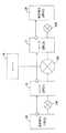
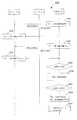
NATには複数の種類があることが知られている。ここで、図8を用いて、NATの種類について説明する。図8(a)は、Full Cone NATと呼ばれる種類のNATを示している。図8(a)を参照して、Full Cone NATを備えたルータは、同じ宅内端末Aのアドレス情報[IPa、Pa]から宅外へ向けて送信されるパケットに対しては、常にルータの同じポート番号[Pb]を割当てて外部のネットワークへ送信する。また、ルータは、外部のネットワークに接続された不特定の宅外端末C、Dから、アドレス情報[IPb、Pb]に向けて送信されたパケットを、全て宅内端末A[IPa、Pa]に転送する。 It is known that there are a plurality of types of NAT. Here, NAT types will be described with reference to FIG. FIG. 8A shows a type of NAT called Full Cone NAT. Referring to FIG. 8A, a router equipped with Full Cone NAT is always the same router for packets transmitted from the same home terminal A address information [IPa, Pa] to the outside of the home. A port number [Pb] is assigned and transmitted to an external network. The router also forwards all packets sent from the unspecified remote terminals C and D connected to the external network toward the address information [IPb, Pb] to the home terminal A [IPa, Pa]. To do.
図8(b)は、Restricted Cone NATと呼ばれる種類のNATを示している。図8(b)を参照して、Restricted Cone NATを備えたルータは、同じ宅内端末Aのアドレス情報[IPa、Pa]から宅外へ向けて送信されるパケットに対しては、常にルータの同じポート番号[Pb]を割当てて外部のネットワークへ送信する。ただし、Full Cone NATとは異なり、ルータは、宅内端末Aがパケットを送信したことがある宅外端末CのIPアドレス[IPc]から、アドレス情報[IPb、Pb]に向けて送信されたパケットしか、宅内端末A[IPa、Pa]への転送を行わない。この時、宅外端末Cのポート番号は何でも良い。 FIG. 8B shows a type of NAT called Restricted Cone NAT. Referring to FIG. 8 (b), a router equipped with Restricted Cone NAT always has the same router for packets transmitted from the same in-home terminal A address information [IPa, Pa] to the outside of the home. A port number [Pb] is assigned and transmitted to an external network. However, unlike the Full Cone NAT, the router only transmits packets sent from the IP address [IPc] of the remote terminal C to which the home terminal A has transmitted packets toward the address information [IPb, Pb]. No transfer to the home terminal A [IPa, Pa] is performed. At this time, the port number of the outside terminal C may be anything.
図8(c)は、Port Restricted Cone NATと呼ばれる種類のNATを示している。図8(c)を参照して、Port Restricted Cone NATを備えたルータは、同じ宅内端末Aのアドレス情報[IPa、Pa]から宅外へ向けて送信されるパケットに対して、常にルータの同じポート番号[Pb]を割当てて外部のネットワークへ送信する。また、Restricted Cone NATとは異なり、ルータは、宅内端末Aがパケットを送信したことがある宅外端末Cのポート番号[Pc1]から、アドレス情報[IPb、Pb]に向けて送信されたパケットしか、宅内端末A[IPa、Pa]への転送を行わない。この時、ルータは、同じ宅外端末Cから送信されたパケットでも、[Pc1]以外のポート番号(例えば[Pc2])から送信されたパケットは全て破棄する。 FIG. 8C shows a type of NAT called Port Restricted Cone NAT. Referring to FIG. 8 (c), the router having the Port Restricted Cone NAT is always the same as the router for packets transmitted from the same home terminal A address information [IPa, Pa] to the outside of the home. A port number [Pb] is assigned and transmitted to an external network. Further, unlike the Restricted Cone NAT, the router only transmits a packet transmitted from the port number [Pc1] of the external terminal C to which the in-home terminal A has transmitted the packet toward the address information [IPb, Pb]. No transfer to the home terminal A [IPa, Pa] is performed. At this time, the router discards all packets transmitted from a port number other than [Pc1] (for example, [Pc2]) even from packets transmitted from the same out-of-home terminal C.
図8(d)は、Symmetric NATと呼ばれる種類のNATを示している。図8(d)を参照して、Symmetric NATを備えたルータは、同じ宅内端末Aのアドレス情報[IPa、Pa]から特定の宅外端末のポート番号へ向けて送信されるパケットに対しては、ルータの特定のポート番号を割当てて外部のネットワークへ送信する。例えば、ルータは、宅内端末A[IPa、Pa]から宅外端末C[IPc、Pc]へ送信されるパケットに対しては、ルータのポート番号[Pb1]を割り当てる。また、ルータは、宅内端末A[IPa、Pa]から宅外端末D[IPd、Pd]へ送信されるパケットに対しては、ルータのポート番号[Pb2]を割り当てる。また、Port Restricted Cone NATと同様に、ルータは、宅内端末Aがパケットを送信したことがある宅外端末のポート番号から送信されたパケットしか、宅内端末A[IPa、Pa]への転送を行わない。 FIG. 8D shows a type of NAT called Symmetric NAT. Referring to FIG. 8 (d), a router equipped with Symmetric NAT does not receive a packet transmitted from the address information [IPa, Pa] of the same in-home terminal A toward a specific port number of the out-of-home terminal. Assign a specific port number of the router and send it to the external network. For example, the router assigns the router port number [Pb1] to a packet transmitted from the in-home terminal A [IPa, Pa] to the out-of-home terminal C [IPc, Pc]. Also, the router assigns the router port number [Pb2] to the packet transmitted from the in-home terminal A [IPa, Pa] to the out-of-home terminal D [IPd, Pd]. Similarly to Port Restricted Cone NAT, the router transfers only packets transmitted from the port number of the external terminal to which the home terminal A has transmitted a packet to the home terminal A [IPa, Pa]. Absent.
これらのルータのNAT機能を利用することで、プライベートネットワーク内に存在する宅内端末は、プライベートIPアドレスを用いて、グローバルネットワーク上に存在する宅外端末との間で通信を行うことができる。 By using the NAT function of these routers, an in-home terminal existing in the private network can communicate with an out-of-home terminal existing on the global network using the private IP address.
しかし、プライベートネットワークとグローバルネットワークとの間にNAT機能を持ったルータを配置するだけでは、プライベートIPアドレスを持った端末が、異なるプライベートネットワークに存在する端末との間でP2P通信を行うことができない。そこで、異なるプライベートネットワークに存在する端末同士が、ルータのNATを越えてP2P通信を実現する手法として、RFC3489 には、STUN(Simple Traversal UDP through NATを用いた手法が開示されている。なお、以降の説明で使用される「パケット」は、全て「UDPパケット」を意味し、メッセージは、全てUDPパケットによって送受信されるものとする。 However, a terminal having a private IP address cannot perform P2P communication with a terminal existing in a different private network only by arranging a router having a NAT function between the private network and the global network. . Therefore, as a technique for realizing P2P communication between terminals existing in different private networks beyond the NAT of the router, a technique using STUN (Simple Traversal UDP through NAT) is disclosed in RFC3489. The “packets” used in the description of FIG. 4 mean all “UDP packets”, and all messages are transmitted and received by UDP packets.
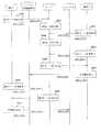
図9は、STUNを用いた手法によってP2P通信を実現する場合の端末間のシーケンスを示す図である。ただし、図9に示すルータ1及びルータ2は、Symmetric NATではないものとする。図9を参照して、端末1は、サーバに対してIP/ポート登録要求を送信する(ステップS501)。サーバは、受信したパケットの送信元アドレス情報(すなわち、送信元IPアドレス及び送信元ポート番号)を登録する(ステップS502)。ここで、サーバには、ルータ1のNATによって、端末1のアドレス情報[IPL1、LP1]から、ルータ1のアドレス情報[IPG1、GP1]に変換された後のアドレス情報[IPG1、GP1]が登録される。 FIG. 9 is a diagram illustrating a sequence between terminals when P2P communication is realized by a technique using STUN. However, it is assumed that the
同様に、端末2は、サーバに対してIP/ポート登録要求を送信する(ステップS503)。サーバは、受信したパケットの送信元アドレス情報(すなわち、送信元IPアドレス及び送信元ポート番号)を登録する(ステップS504)。ここで、サーバには、ルータ2のNATによって、端末2のアドレス情報[IPL2、LP2]から、ルータ2のアドレス情報[IPG2、GP2]に変換された後のアドレス情報[IPG2、GP2]が登録される。 Similarly, the
次に、端末2は、端末1にアクセスするときに用いるアドレス情報を取得するために、IP/ポート取得要求をサーバに対して送信する(ステップS505)。サーバは、その応答として、ステップS502で登録したアドレス情報[IPG1、GP1]を設定したIP/ポート取得応答を端末2に返す(ステップS506)。 Next, the
端末2は、端末1にアクセスするときに用いるアドレス情報[IPG1、GP1]を取得すれば、取得したアドレス情報[IPG1、GP1]に向けて、P2P開始要求を送信する(ステップS507)。ルータ2は、端末2が送信したP2P開始要求をルータ1に中継する。ここで、ルータ1がFull Cone NATであれば、端末2から送信されたP2P開始要求は、端末1へ転送され、端末1と端末2との間にP2P通信路が確立する。 If the
一方、ルータ1がFull Cone NATでなければ、端末2から送信されたP2P開始要求は、ルータ1よって破棄され、端末1[IPL1、LP1]に転送されることはない。 On the other hand, if the
ただし、ルータ2のNATには、端末2が送信したP2P開始要求を中継する際に、中継したP2P開始要求と逆方向のパケットを、端末2まで転送するための設定が行われる。すなわち、ルータ2のNATには、ルータ2がFull Cone NATである場合は、端末1からルータ1[IPG1、GP1]を介して、ルータ2[IPG2、GP2]に届いたパケットを、端末2[IPL2、LP2]に転送するという設定が行われる。また、ルータ2がRestricted Cone NATである場合には、送信元IPアドレス[IPG1]から、ルータ2[IPG2、GP2]に届いたパケットを、端末2[IPL2、LP2]に転送するという設定が行われる。また、ルータ2がPort Restricted Cone NATである場合には、端末1からルータ1[IPG1、GP1]を介して、ルータ2[IPG2、GP2]に届いたパケットを、端末2[IPL2、LP2]に転送するという設定が行われる。 However, the NAT of the
次に、端末1は、端末2にアクセスするときに用いるアドレス情報を取得するために、IP/ポート取得要求をサーバに対して送信する(ステップS508)。サーバは、その応答として、ステップS504で登録したアドレス情報[IPG2、GP2]を設定したIP/ポート取得応答を端末1に返す(ステップS509)。 Next, the
端末1は、端末2にアクセスするときに用いるアドレス情報[IPG2、GP2]を取得すれば、取得したアドレス情報[IPG2、GP2]に向けて、P2P開始要求を送信する(ステップS510)。ルータ1は、端末1が送信したP2P開始要求をルータ2に中継する。ルータ2のNATには、上述したように、端末1からルータ1を介して、ルータ2[IPG2、GP2]に届いたパケットを端末2[IPL2、LP2]に転送する設定がある。そのため、ルータ2は、端末1が送信したP2P開始要求を端末2に転送することができる。 If the
また、ルータ1のNATには、端末1が送信したP2P開始要求を中継する際に、中継したP2P開始要求と逆方向のパケットを、端末1まで転送するための設定が行われる。すなわち、ルータ1のNATには、ルータ1がRestricted Cone NATである場合は、送信元IPアドレス[IPG2]から、ルータ1[IPG1、GP1]に届いたパケットを、端末1[IPL1、LP1]に転送するという設定が行われる。また、ルータ1がPort Restricted Cone NATである場合には、端末2からルータ2[IPG2、GP2]を介して、ルータ1[IPG1、GP1]に届いたパケットを、端末1[IPL1、LP1]に転送するという設定が行われる。 The NAT of the
P2P開始要求を受信した端末2は、端末1に対して、P2P開始応答を送信する(ステップS511)。このとき、ルータ1のNATには、上述したように、端末2からルータ2を介して、ルータ1[IPG1、GP1]に届いたパケットを端末1[IPL1、LP1]に転送する設定がある。そのため、ルータ1は、端末2から送信されたP2P開始応答を端末1に転送することができる。以上がルータ1及びルータ2がSymmetric NAT以外の時におけるSTUNによるP2P通信路の確立手法である。 The
一方、端末1と端末2との間の経路に、Symmetric NATであるルータが存在する場合には、STUNによってP2P通信路を確立する上で以下のような問題が発生する。その問題を図10及び図11を用いて説明する。図10は、ルータ1がSymmetric NATである場合に発生する問題を説明する図である。図11は、ルータ2がSymmetric NATである場合に発生する問題を説明する図である。 On the other hand, when a router that is a Symmetric NAT exists in the path between the terminal 1 and the
図10を参照して、ステップS601〜S604は、図9におけるステップS501〜S504と同様の処理であるため説明を省略する。次に、端末2は、端末1にアクセスするときに用いるアドレス情報を取得するために、IP/ポート取得要求をサーバに対して送信する(ステップS605)。サーバは、その応答として、ステップS602で登録したアドレス情報[IPG1、GP1]を設定したIP/ポート取得応答を端末2に返す(ステップS606)。 Referring to FIG. 10, steps S601 to S604 are the same as steps S501 to S504 in FIG. Next, the
端末2は、端末1にアクセスするときに用いるアドレス情報[IPG1、GP1]を取得すれば、取得したアドレス情報[IPG1、GP1]に向けて、P2P開始要求を送信する(ステップS607)。ルータ2は、端末2が送信したP2P開始要求をルータ1に中継する。ここでルータ1がSymmetric NATであるため、端末2から送信されたP2P開始要求のパケットは、ルータ1よって破棄され、端末1[IPL1、LP1]に転送されない。 If the
ただし、ルータ2のNATには、端末2が送信したP2P開始要求を中継する際に、中継したP2P開始要求と逆方向のパケットを、端末2まで転送するための設定が行われる。すなわち、ルータ2のNATには、ルータ2がFull Cone NATである場合は、端末1からルータ1[IPG1、GP1]を介して、ルータ2[IPG2、GP2]に届いたパケットを、端末2[IPL2、LP2]に転送するという設定が行われる。また、ルータ2がRestricted Cone NATである場合は、送信元IPアドレス[IPG1]から、ルータ2[IPG2、GP2]に届いたパケットを、端末2[IPL2、LP2]に転送するという設定が行われる。また、ルータ2がPort Restricted Cone NATである場合は、端末1からルータ1[IPG1、GP1]を介して、ルータ2[IPG2、GP2]に届いたパケットを、端末2[IPL2、LP2]に転送するという設定が行われる。 However, the NAT of the
次に、端末1は、端末2にアクセスするときに用いるアドレス情報を取得するために、IP/ポート取得要求をサーバに対して送信する(ステップS608)。サーバは、その応答として、ステップS604で登録したアドレス情報[IPG2、GP2]を設定したIP/ポート取得応答を端末1に返す(ステップS609)。 Next, the
端末1は、端末2にアクセスするときに用いるアドレス情報[IPG2、GP2]を取得すれば、取得したアドレス情報[IPG2、GP2]に向けて、P2P開始要求を送信する(ステップS610)。このとき、ルータ1は、Symmetric NATであるため、端末1から送信されたP2P開始要求に、[GP1]以外のポート番号(例えば、[GP3])を割り当てることになる。 If the
ここで、ルータ2がFull Cone NAT、あるいはRestricted Cone NATである場合には、端末1が送信したP2P開始要求は、ルータ2によって端末2[IPL2、LP2]に転送され、端末1と端末2との間におけるP2P通信路が確立する。しかし、ルータ2がPort Restricted Cone NAT、あるいはSymmetric NATである場合には、端末1が送信したP2P開始要求は、ルータ2によって破棄され、端末2に転送されない。このため、端末1と端末2との間におけるP2P通信路の確立は失敗する。 Here, when the
なお、ルータ2がSymmetric NAT(図11参照)である場合も、同様の問題によって、P2P通信路の確立は失敗する。 Even when the
このように、ルータ1またはルータ2のいずれかがSymmetric NATである場合には、STUNによるP2P通信路確立の可能性は高いとは言い難い。そこで、このような問題を解決するために、従来、ルータ1及びルータ2がSymmetric NATである場合にも、P2P通信路の確立を成功させる手法が開示されている(例えば、特許文献1参照)。 Thus, if either
図12は、従来の手法によるP2P通信路の確立手順を示すシーケンス図である。図12を参照して、ステップS801〜S804は、図9におけるステップS501〜S504と同様の処理であるため説明を省略する。端末2は、端末1にP2P通信を要求するために、P2P通信要求をサーバに対して送信する(ステップS805)。このとき、端末2は、P2P通信要求で使用する送信元ポート番号を、IP/ポート取得要求で使用した送信元ポート番号[LP2]から[LP2+a]に変更する。aは、任意の整数である。 FIG. 12 is a sequence diagram showing a procedure for establishing a P2P communication path according to a conventional method. Referring to FIG. 12, steps S801 to S804 are the same as steps S501 to S504 in FIG. The
端末2が新しいポート番号[LP2+a]を使う理由は、ルータ2に、P2P通信要求の送信元ポート番号として、新しい送信元ポート番号[GP2+b]を使わせるためである。bは、ルータ2におけるNATの不確定な増分値である。 The reason why the
P2P通信要求を受取ったサーバは、アドレス情報[IPG2、GP2+b]を設定したIP/ポート通知を端末1に送信する(ステップS806)。 The server that has received the P2P communication request transmits an IP / port notification in which the address information [IPG2, GP2 + b] is set to the terminal 1 (step S806).
IP/ポート通知を受取った端末1は、P2P通信を許可する場合は、サーバに対してP2P開始許可を送信する(ステップS807)。このとき、端末1は、P2P開始許可で使用する送信元ポート番号を、IP/ポート取得要求で使用した送信元ポート番号[LP1]から[LP1+d]に変更して送信する。端末1が[LP1+d]という新しいポート番号を使う理由は、ルータ1に、P2P通信許可の送信元ポート番号として、新しい送信元ポート番号[GP1+d]を使わせるためである。dは、任意の整数であり、ルータ1におけるNATの不確定な増分値である。 The
さらに、IP/ポート通知によって、端末2にアクセスするときに用いるアドレス情報[IPG2、GP2+b]を取得した端末1は、取得したアドレス情報[IPG2、GP2+b+n]に向けて、P2P開始要求を送信する(ステップS808)。 Further, the
なお、ステップS807で送信されるP2P通信許可と、ステップS808で送信されるP2P開始要求とは、極めて短時間内に連続で送信される。このため、ルータ1によって、P2P通信許可の送信元ポート番号が[LP1+c]から[GP1+d]に変換された場合、P2P開始要求の送信元ポート番号は、[LP1+c+1]から[GP1+d+1]に変換される。 Note that the P2P communication permission transmitted in step S807 and the P2P start request transmitted in step S808 are continuously transmitted within an extremely short time. Therefore, when the transmission source port number for P2P communication permission is converted from [LP1 + c] to [GP1 + d] by the
また、ルータ1のNATには、端末1が送信したP2P開始要求を中継する際に、中継したP2P開始要求と逆方向のパケットを、端末1まで転送するための設定が行われる。すなわち、ルータ1のNATには、端末2からルータ2[IPG2、GP2+b+n]を介して、ルータ1[IPG1、GP1+d+1]に届いたパケットを、端末1[IPL1、LP1+c+1]に転送するという設定が行われる。ここで、nは任意の整数値である。 The NAT of the
サーバは、ステップS807で端末1が送信したP2P通信許可を受け取ると、端末2に対して、ルータ1のアドレス情報[IPG1、GP1+d]を設定したIP/ポート取得応答を送信する(ステップS809)。When the server receives the P2P communication permission transmitted by the
次に、端末2は、IP/ポート取得応答によって、端末1にアクセスするときに用いるアドレス情報(すなわち、ルータ1のアドレス情報)[IPG1、GP1+d]を受取ったら、直ちに端末1へP2P開始要求を送信する(ステップS810)。このとき端末2は、ルータ1のポート番号[GP1+d+1]に向けて、送信元ポート番号を[LP2+a+1]から1つずつ増加させながらn個のP2P開始要求を送信する。このP2P開始要求の送信元ポート番号は、ルータ2によって、[GP2+b+m]から[GP2+b+m+n−1]までのポート番号に変換される。Next, when the
端末2から送信された複数のP2P開始要求のいずれかは、逆方向のパケットを端末1まで転送するルータ1の設定と一致するため、端末1まで転送される。P2P開始要求を受取った端末1は、その応答としてP2P開始応答を送信する(ステップS811)。これによって、端末1と端末2との間におけるP2P通信路が確立する。
しかしながら、図12に示した従来の手法においては、端末2は、端末1がステップS808でP2P開始要求を送信したポート番号を予測するために、ステップS810で複数のP2P開始要求を送信している。このために、P2P通信路の確立までの接続時間が遅延するという問題や、トラフィックが増大するという問題が発生していた。また、さらに、ルータ2の種類によっては、端末2から送信された複数のP2P開始要求に割り当てられるポート番号がランダムに変化する場合がある。このような場合、端末2から送信されたP2P開始要求には、順番にポート番号が割当てられないため、P2P通信路の接続性が悪くなるという問題が発生する可能性があった。 However, in the conventional method illustrated in FIG. 12, the
それ故に、本発明の目的は、他の通信端末との間でP2P通信路を確立するときに、短時間かつ少ないトラフィックで、高い接続性を実現する通信端末及び通信方法を提供することである。 SUMMARY OF THE INVENTION Therefore, an object of the present invention is to provide a communication terminal and a communication method that realize high connectivity in a short time and with little traffic when establishing a P2P communication path with another communication terminal. .
本発明は、ルータによってグローバルネットワークと接続されたプライベートネットワーク上に存在し、ルータを介して他のネットワーク上の通信端末と一対一の相互接続を行う通信端末に向けられている。そして、上記目的を達成するために、本発明の通信端末は、アドレス情報決定部と、アドレス情報交換部と、通信制御部と、通信部とを備える。 The present invention is directed to a communication terminal that exists on a private network connected to a global network by a router and performs one-to-one interconnection with a communication terminal on another network via the router. And in order to achieve the said objective, the communication terminal of this invention is provided with an address information determination part, an address information exchange part, a communication control part, and a communication part.
アドレス情報決定部は、グローバルネットワーク上にあるサーバとの間で所定のメッセージを送受信することで、ルータの中継特性を調査して、他のネットワーク上の通信端末との一対一の相互接続に使用するルータのアドレス情報を決定する。アドレス情報交換部は、アドレス情報決定部によって決定されたルータのアドレス情報を、他のネットワーク上の通信端末との間で互いに交換する。通信制御部は、アドレス情報交換部で交換されたルータのアドレス情報に基づいて、他のネットワーク上の通信端末との間で一対一の相互接続を行う。通信部は、通信端末の全ての通信を行う。アドレス情報決定部は、ルータの中継特性がPort Reuseである場合に、他のネットワーク上の通信端末と一対一の相互接続で使用する通信端末自身のポート番号を少なくとも含むアドレス情報を、ルータのアドレス情報として決定する。 The address information decision unit investigates the relay characteristics of routers by sending and receiving predetermined messages to and from servers on the global network, and is used for one-to-one interconnection with communication terminals on other networks Determine the router address information. The address information exchange unit exchanges the router address information determined by the address information determination unit with another communication terminal on another network. The communication control unit performs one-to-one interconnection with communication terminals on other networks based on the address information of the router exchanged by the address information exchange unit. The communication unit performs all communication of the communication terminal. When the router relay characteristic is Port Reuse, the address information determination unit obtains address information including at least a port number of the communication terminal itself used for one-to-one interconnection with a communication terminal on another network. Determine as information.
より特定的には、アドレス情報決定部は、アドレス情報調査要求部と、アドレス情報受信部と、中継特性判断部と、通信ポート決定部とを含む。アドレス情報調査要求部は、ルータを介して、サーバに所定のメッセージを送信することで、サーバにルータのアドレス情報を要求する。アドレス情報受信部は、要求に対する応答として、サーバからルータのアドレス情報を受信する。中継特性判断部は、アドレス情報受信部が受信したルータのアドレス情報に基づいて、ルータの中継特性を判断する。通信ポート決定部は、中継特性判断部が判断したルータの中継特性に基づいて、他のネットワーク上の通信端末と一対一の相互接続で使用する通信端末自身のポート番号を決定する。More specifically, the address information determination unit includes an address informationinvestigation request unit, an address information reception unit, a relay characteristic determination unit, and acommunication port determination unit. The address informationinvestigation request unit requests the server for address information of the router by transmitting a predetermined message to the server via the router. The address information receiving unit receives router address information from the server as a response to the request. The relay characteristic determining unit determines the relay characteristic of the router based on the router address information received by the address information receiving unit.The communication port determining unit determines the port number of the communication terminal used for one-to-one interconnection with the communication terminal on another network based on the relay characteristic of the router determined by the relay characteristic determining unit.
好ましくは、アドレス情報調査要求部は、通信端末の所定のポート番号から、サーバの第1のポート番号に向けて第1のポート番号調査要求メッセージと、サーバの第2のポート番号に向けて第2のポート番号調査要求メッセージとを連続して送信する。アドレス情報受信部は、サーバから、第1のポート番号調査要求メッセージに対する応答である第1のポート番号調査応答メッセージと、第2のポート番号調査要求メッセージに対する応答である第2のポート番号調査応答メッセージとを受信する。中継特性判断部は、アドレス情報受信部が受信した第1のポート番号調査応答メッセージと、第2のポート番号調査応答メッセージとに基づいて、ルータの中継特性を判断する。 Preferably, the address information investigation request unit starts from a predetermined port number of the communication terminal toward the first port number of the server and the first port number investigation request message toward the first port number of the server and the second port number of the server. 2 port number investigation request messages are continuously transmitted. The address information receiving unit receives, from the server, a first port number investigation response message that is a response to the first port number investigation request message and a second port number investigation response that is a response to the second port number investigation request message. Message and receive. The relay characteristic determination unit determines the relay characteristic of the router based on the first port number investigation response message and the second port number investigation response message received by the address information reception unit.
第1のポート番号調査応答メッセージには、ルータのIPアドレスと、第1のポート番号調査要求メッセージをサーバに中継したときのルータの送信元ポート番号とが含まれる。第2のポート番号調査応答メッセージには、ルータのIPアドレスと、第2のポート番号調査要求メッセージをサーバ中継したときルータの送信元ポート番号とが含まれる。中継特性判断部は、第1のポート番号調査要求メッセージを送信した通信端末の所定のポート番号と、第1のポート番号調査応答メッセージに含まれるルータの送信元ポート番号とが一致する場合に、ルータの中継特性がPort Reuseの性質を持っていると判断する。 The first port number investigation response message includes the IP address of the router and the source port number of the router when the first port number investigation request message is relayed to the server. The second port number investigation response message includes the IP address of the router and the transmission source port number of the router when the second port number investigation request message is relayed to the server. The relay characteristic determining unit, when the predetermined port number of the communication terminal that has transmitted the first port number investigation request message matches the transmission source port number of the router included in the first port number investigation response message, It is determined that the relay characteristic of the router has the property of Port Reuse.
中継特性判断部は、第1のポート番号調査応答メッセージに含まれるルータの送信元ポート番号と、第2のポート番号調査応答メッセージに含まれるルータの送信元ポート番号とが一致する場合に、ルータの中継特性がCone系のNAT機能を持っていると判断する。また、中継特性判断部は、第1のポート番号調査応答メッセージに含まれるルータの送信元ポート番号と、第2のポート番号調査応答メッセージに含まれるルータの送信元ポート番号とが一致しない場合に、ルータの中継特性がSymmetric NATの機能を持っていると判断する。 The relay characteristic determining unit determines whether the router source port number included in the first port number investigation response message matches the router source port number included in the second port number investigation response message. Is determined to have a Cone-based NAT function. Further, the relay characteristic determination unit determines that the source port number of the router included in the first port number investigation response message does not match the source port number of the router included in the second port number investigation response message. Then, it is determined that the relay characteristic of the router has the function of Symmetric NAT.
通信ポート決定部は、中継特性判断部によって、ルータの中継特性がPort Reuseでなく、かつCone系のNAT機能を持っていると判断された場合に、第1のポート番号調査応答メッセージに含まれるルータの送信元ポート番号を、他のネットワーク上の通信端末と一対一の相互接続で使用するポート番号として用いる。 The communication port determining unit is included in the first port number investigation response message when the relay characteristic determining unit determines that the relay characteristic of the router is not Port Reuse and has a Cone-type NAT function. The source port number of the router is used as a port number used for one-to-one interconnection with a communication terminal on another network.
通信ポート決定部は、中継特性判断部によって、ルータの中継特性がPort Reuseでなく、かつSymmetric NATの機能を持っていると判断された場合に、第2のポート番号調査応答メッセージに含まれるルータの送信元ポート番号と、第1のポート番号調査応答メッセージに含まれるルータの送信元ポート番号との差分を、第2のポート番号調査応答メッセージに含まれるルータの送信元ポート番号に加算したポート番号を、他のネットワーク上の通信端末と一対一の相互接続で使用するポート番号として用いる。 The communication port determining unit determines whether the relay characteristic determining unit determines that the relay characteristic of the router is not Port Reuse and has the function of Symmetric NAT, and the router included in the second port number investigation response message. Port obtained by adding the difference between the source port number of the router and the source port number of the router included in the first port number investigation response message to the source port number of the router included in the second port number investigation response message The number is used as a port number used for one-to-one interconnection with a communication terminal on another network.
より特定的には、アドレス情報交換部は、中継情報送信部と、中継情報受信部とを含む。中継情報送信部は、サーバを介して、他のネットワーク上の通信端末との一対一の相互接続に使用するルータのアドレス情報を設定したメッセージを、他のネットワーク上の通信端末に送信する。中継情報受信部は、サーバを介して、自通信端末と一対一の相互接続に使用するアドレス情報が設定されたメッセージを、他のネットワーク上の通信端末から受信する。More specifically, the address information exchange unit includes a relay information transmitting unit, a relay informationreceiving unit. The relay information transmitting unit transmits a message in which address information of a router used for one-to-one interconnection with a communication terminal on another network is set to the communication terminal on another network via the server. Relay informationreceiving unit, through the server, the message address information is set to be used for one-to-one interconnection and self communication terminal is received from the communication terminal on another network.
好ましくは、通信制御部は、通信部を介して、アドレス情報交換部によって交換されたアドレス情報宛てに、一対一の相互接続の開始を要求するメッセージを送信し、他のネットワーク上の通信端末から一対一の相互接続の開始を要求するメッセージを受信した場合に、他のネットワーク上の通信端末との間で一対一の相互接続を行う。 Preferably, the communication control unit transmits a message requesting the start of a one-to-one interconnection to the address information exchanged by the address information exchange unit via the communication unit, and from a communication terminal on another network When a message requesting the start of a one-to-one interconnection is received, a one-to-one interconnection is performed with a communication terminal on another network.
また、本発明は、ルータによってグローバルネットワークと接続されたプライベートネットワーク上に存在し、ルータを介して他のネットワーク上の通信端末と一対一の相互接続を行う通信端末が実行する通信方法にも向けられている。上記目的を達成するために、本発明の通信方法は、通信端末が、グローバルネットワーク上にあるサーバとの間で所定のメッセージを送受信することで、ルータの中継特性を調査し、ルータの中継特性がPort Reuseである場合に、他のネットワーク上の通信端末と一対一の相互接続で使用するポート番号を少なくとも含むアドレス情報を、ルータのアドレス情報として決定し、決定されたルータのアドレス情報を、他のネットワーク上の通信端末との間で互いに交換し、交換されたアドレス情報に基づいて、他のネットワーク上の通信端末との間で一対一の相互接続を実施する。 The present invention is also directed to a communication method executed by a communication terminal that exists on a private network connected to a global network by a router and performs one-to-one interconnection with a communication terminal on another network via the router. It has been. In order to achieve the above object, the communication method of the present invention investigates the relay characteristics of a router by allowing a communication terminal to send and receive a predetermined message to and from a server on the global network, and Is Port Reuse, address information including at least a port number used for one-to-one interconnection with a communication terminal on another network is determined as router address information, and the determined router address information is Exchanges are made with communication terminals on other networks, and one-to-one interconnection is performed with communication terminals on other networks based on the exchanged address information.
以上のように、本発明の通信端末及び通信方法によれば、サーバとの間で所定のメッセージを送受信し、送受信したメッセージに基づいてルータの中継特性を調査し、ルータの中継特性がPort Reuseである場合に、他の通信端末とのP2P通信に使用する通信端末自身のポート番号を少なくとも含むアドレス情報を、ルータのアドレス情報として決定する。これによって、本発明の通信端末及び通信方法は、ルータの中継特性がPort Reuseであれば、サーバを用いたルータが使用するアドレス情報を決定するための手順を簡略化することができる。 As described above, according to the communication terminal and the communication method of the present invention, a predetermined message is transmitted / received to / from the server, the relay characteristic of the router is investigated based on the transmitted / received message, and the relay characteristic of the router is Port Reuse. The address information including at least the port number of the communication terminal itself used for P2P communication with other communication terminals is determined as the address information of the router. Thus, the communication terminal and the communication method of the present invention can simplify the procedure for determining address information used by the router using the server if the relay characteristic of the router is Port Reuse.
また、本発明の通信端末及び通信方法は、ルータの中継特性がPort Reuseであり、かつSymmetric NATである場合に、ルータが使用するポート番号を予測するための手順を省略することができる。故に、本発明の通信端末及び通信方法によれば、他の通信端末とのP2P通信路の確立時に、より短時間かつ少ないトラフィックで、高い接続性を実現することができる。 Further, the communication terminal and the communication method of the present invention can omit the procedure for predicting the port number used by the router when the relay characteristic of the router is Port Reuse and Symmetric NAT. Therefore, according to the communication terminal and the communication method of the present invention, when establishing a P2P communication path with another communication terminal, high connectivity can be realized in a shorter time and with less traffic.
以下に、本発明の一実施形態について、図面を参照しながら説明する。 An embodiment of the present invention will be described below with reference to the drawings.
図1は、本発明の一実施形態に係る通信システムのネットワーク構成の一例を示す図である。図1において、グローバルネットワーク300と、プライベートネットワーク100とが、グローバルIPアドレス[IPG1]を有するルータ11を介して接続されている。また、グローバルネットワーク300と、プライベートネットワーク200とが、グローバルIPアドレス[IPG2]を有するルータ21を介して接続されている。グローバルネットワーク300には、サーバ30が接続されている。プライベートネットワーク100には、プライベートIPアドレス[IPL1]を有する通信端末(宅内端末)10が接続されている。プライベートネットワーク200には、プライベートIPアドレス[IPL2]を有する通信端末(宅内端末)20が接続されている。 FIG. 1 is a diagram illustrating an example of a network configuration of a communication system according to an embodiment of the present invention. In FIG. 1, a
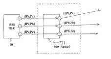
ルータ11は、Symmetric NATであり、かつPort Reuseの性質を持ったルータである。ここで、Port Reuseの性質を持ったルータ11について、図2を用いて説明する。図2において、Port Reuseの性質を持ったルータ11は、通信端末10が送信したパケットを中継する際に、中継するパケットの送信元ポート番号と同じポート番号を、ルータ11の送信元ポート番号として割り当てることを特徴とする。 The
例えば、ルータ11は、通信端末10のポート番号[Pa]から送信されたパケットを中継する際には、中継するパケットの送信元ポート番号として、ルータ11のポート番号[Pa]を割り当てる。また、ルータ11は、通信端末10のポート番号[Pb]から送信されたパケットを中継する際には、中継するパケットの送信元ポート番として、ルータ11のポート番号[Pb]を割り当てる。また、ルータ11は、通信端末10のポート番号[Pc]から送信されたパケットを中継する際には、中継するパケットの送信元ポート番として、ルータ11のポート番号[Pc]を割り当てる。一方、ルータ21は、Full Cone NATであり、かつPort Reuseの性質を持っていないルータである。 For example, when relaying a packet transmitted from the port number [Pa] of the
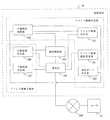
図3Aは、通信端末10の構成の一例を示すブロック図である。図3Aにおいて、通信端末10は、アドレス情報調査要求部101、アドレス情報受信部102、通信ポート決定部103、中継特性判断部104、中継情報送信部105、中継情報受信部106、通信制御部107、及び通信部108を備える。 FIG. 3A is a block diagram illustrating an example of the configuration of the
アドレス情報調査要求部101は、自身が接続するルータ11に割り当てられるポート番号を調査するメッセージ(ポート番号調査要求メッセージ)をサーバ30に向けて送信する。アドレス情報受信部102は、ポート番号調査要求メッセージに対する応答として、ルータ11に割り当てられるポート番号を含んだメッセージ(ポート番号調査応答メッセージ)をサーバ30から受信する。中継特性判断部104は、受信したポート番号調査応答メッセージに基づいて、ルータ11の中継特性を判断する。通信ポート決定部103は、ルータ11の中継特性に基づいて、通信端末10がP2P通信で使用するポート番号を決定する。 The address information
中継情報送信部105は、ルータ11のIPアドレスと、通信端末10がP2P通信で使用するポート番号とを含むメッセージ(IP/ポート通知メッセージ)を、サーバ30に向けて送信する。中継情報受信部106は、通信端末20が送信したIP/ポート通知メッセージをサーバ30から受信する。通信制御部107は、通信部108を制御して、通信端末20とのP2P通信を行う。通信部108は、通信端末10に関する全ての通信を行う。 The relay
なお、アドレス情報調査要求部101、アドレス情報受信部102、通信ポート決定部103、及び中継特性判断部104は、通信端末20とのP2P通信に使用するアドレス情報(IPアドレス及びポート番号)を決定するので、アドレス情報決定部と記してもよい。また、中継情報送信部105、及び中継情報受信部106は、決定したアドレス情報を通信端末20との間で交換するので、アドレス情報交換部と記してもよい。 The address information
図3Bは、通信端末20の構成の一例を示すブロック図である。図3Bにおいて、通信端末20は、アドレス情報調査要求部201、アドレス情報受信部202、通信ポート決定部203、中継特性判断部204、中継情報送信部205、中継情報受信部206、通信制御部207、及び通信部208を備える。なお、通信端末20の各構成は、上述した通信端末10と同様であるため説明を省略する。 FIG. 3B is a block diagram illustrating an exemplary configuration of the
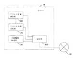
図3Cは、サーバ30の構成の一例を示すブロック図である。図3Cにおいて、サーバ30は、アドレス情報調査部301、アドレス情報送信部302、中継情報転送部303、及び通信部304を備える。 FIG. 3C is a block diagram illustrating an exemplary configuration of the
アドレス情報調査部301は、通信端末10又は20からポート番号調査要求メッセージを受信すると、受信メッセージ(受信パケットのヘッダ)から、送信元IPアドレス及び送信元ポート番号を抜き出す。アドレス情報送信部302は、アドレス情報調査部301が抜き出したIPアドレス及び送信元ポート番号を含んだメッセージ(ポート番号調査応答メッセージ)を通信端末10又は20に対して返信する。中継情報転送部303は、一方の通信端末から受信したIP/ポート通知メッセージを、他方の通信端末に中継する。通信部304は、サーバ30に関する全ての通信を行う。 When receiving the port number investigation request message from the
図4は、本発明の一実施形態に係る通信システムがP2P通信路確立時に実行する動作を説明する図である。図4において、本発明の一実施形態に係る通信システムは、P2P通信路確立時に、NAT調査フェーズ(ステップS100、S200)、P2P通信ポート交換フェーズ(ステップS300)、及びP2P通信路確立フェーズ(ステップS400)を実行する。 FIG. 4 is a diagram for explaining an operation performed when the communication system according to the embodiment of the present invention establishes a P2P communication path. In FIG. 4, the communication system according to an embodiment of the present invention, when establishing a P2P communication path, performs a NAT investigation phase (steps S100 and S200), a P2P communication port exchange phase (step S300), and a P2P communication path establishment phase (steps). S400) is executed.
NAT調査フェーズ(ステップS100、S200)は、通信端末10及び通信端末20が、サーバ30と通信を行って、自身が接続されてルータ11又はルータ21の中継特性を調査し、P2P通信において互いにアクセス可能な通信ポートを決定する。具体的には、通信端末10及び通信端末20は、ルータ11又はルータ21の中継特性として、NATの種類(例えば、Full Cone NAT、Symmetric NATなど)と、Port Reuseの性質を持っているかどうかを調査する。 In the NAT investigation phase (steps S100 and S200), the
P2P通信ポート交換フェーズ(ステップS300)は、通信端末10及び通信端末20が、NAT調査フェーズで決定した通信ポートをサーバ30経由で互いに交換する。P2P通信路確立フェーズ(ステップS400)は、通信端末10及び通信端末20が、P2P通信ポート交換フェーズで交換した互いの通信ポートに向けてパケットを送信して、P2P通信路を確立する。 In the P2P communication port exchange phase (step S300), the
図5Aは、通信端末10におけるNAT調査フェーズ(ステップS100)の詳細な動作を示すフローチャートである。以下、図5Aを参照しながら、通信端末10におけるNAT調査フェーズ(ステップS100)について説明する。なお、図5Aにおいて、各メッセージの下の(IPG1、GP11)等の記載は、各メッセージに含まれる送信元アドレス情報(送信元IPアドレス、及び送信元ポート番号)を示している。 FIG. 5A is a flowchart showing a detailed operation of the NAT investigation phase (step S100) in the
まず、通信端末10において、アドレス情報調査要求部101は、通信端末10のポート番号[LP1]から、サーバ30のポート番号[SP0]に向けて、ポート番号調査要求1メッセージを送信する(ステップS101)。 First, in the
サーバ30において、アドレス情報調査部301は、通信部304を介して、ポート番号調査要求1メッセージを受信すると、受信メッセージ(受信パケットのヘッダ)から、送信元IPアドレス、及び送信元ポート番号(すなわち、ルータ11のIPアドレス[IPG1]、及び送信元ポート番号[GP11])を抜き出す。アドレス情報送信部302は、抜き出したルータ11のIPアドレス[IPG1]、及び送信元ポート番号[GP11]をポート番号調査応答1メッセージに含めて、通信端末10に返信する(ステップS102)。 In the
続いて、通信端末10において、アドレス情報調査要求部101は、通信端末10のポート番号[LP1]から、サーバ30のポート番号[SP1]に向けて、ポート番号調査要求2メッセージを送信する(ステップS103)。 Subsequently, in the
サーバ30において、アドレス情報調査部301は、通信部304を介して、ポート番号調査要求2メッセージを受信すると、受信メッセージ(受信パケットのヘッダ)から、送信元IPアドレス、及び送信元ポート番号(すなわち、ルータ11のIPアドレス[IPG1]、及び送信元ポート番号[GP12])を抜き出す。アドレス情報送信部302は、アドレス情報調査部301が抜き出したルータ11のIPアドレス[IPG1]、及び送信元ポート番号[GP12]をポート番号調査応答2メッセージに含めて、通信端末10に返信する(ステップS104)。 In the
ここで、ステップS101及びS103において、通信端末10が、同じポート番号[LP1]からサーバ30の2つのポート番号[SP0、SP1]に対して、ポート番号調査要求メッセージを送信する理由を説明する。通信端末10は、サーバ30が受信した2つのポート番号調査要求メッセージに含まれるルータ11の送信元ポート番号が等しい(すなわち、GP11=GP12である)場合には、ルータ11がCone系(Full Cone、Restricted Cone、又はPort Restricted Cone)NATであると判断できる。また、通信端末10は、サーバ30が受信した2つのポート番号調査要求メッセージに含まれる送信元ポート番号が異なる(すなわち、GP11≠GP12である)場合には、ルータ11がSymmetric NATであると判断できる。すなわち、通信端末10は、同じポート番号[LP1]からサーバ30の2つのポート番号[SP0、SP1]に対して、ポート番号調査要求メッセージを送信することで、ルータ11のNATの種類を調査することができる。Here, in steps S101 and
なお、通信端末10は、上述した以外の方法を用いても、ルータ11のNATの種類を調査してもよい。例えば、通信端末10は、異なるIPアドレスを持つ2つのサーバに対してルータ経由でパケットを送信し、そのときに割り当てられるルータのポート番号が等しいか、あるいは異なるかで、ルータのNATの種類を調査してもよい。 Note that the
通信端末10において、アドレス情報受信部102は、通信部108を介して、ポート番号調査応答1メッセージ、及びポート番号調査応答2メッセージを受信すると、中継特性判断部104に受信メッセージを渡す。中継特性判断部104は、ポート番号調査応答1メッセージに含まれるルータ11のポート番号[GP11]と、ポート番号調査要求1メッセージを送信したときの通信端末10のポート番号[LP1]とが一致するかどうかをチェックする(ステップS105)。中継特性判断部104は、ルータ11のポート番号[GP11]と、通信端末10のポート番号[LP1]とが一致する(すなわち、GP11=LP1である)場合には、ルータ11のNATが、Port Reuseの性質を持っていると判断する(ステップS106)。 In the
さらに、通信端末10において、中継特性判断部104は、アドレス情報受信部102が受信したポート番号調査応答1メッセージと、ポート番号調査応答2メッセージとに含まれるルータ11のポート番号が一致するか否かをチェックする(ステップS107)。中継特性判断部104は、ルータ11のポート番号が一致している場合には、ルータ11がCone系NATであると判断し、ルータ11のポート番号が一致していない場合には、ルータ11がSymmetric NATであると判断する(ステップS108)。 Further, in
通信ポート決定部103は、中継特性判断部104が判断したルータ11の中継特性に基づいて、通信端末10がP2P通信で使用するポート番号を決定する(ステップS109)。なお、P2P通信ポート決定処理(ステップS109)の詳細については後述する。 The communication
図5Bは、通信端末20におけるNAT調査フェーズ(ステップS200)の詳細な動作を示すフローチャートである。以下、図5Bを参照しながら、通信端末20におけるNAT調査フェーズ(ステップS200)処理について説明する。 FIG. 5B is a flowchart showing the detailed operation of the NAT investigation phase (step S200) in the
まず、通信端末20において、アドレス情報調査要求部201は、通信端末20のポート番号[LP2]から、サーバ30のポート番号[SP0]に向けて、ポート番号調査要求1メッセージを送信する(ステップS201)。First, in the
サーバ30において、アドレス情報調査部301は、通信部304を介して、ポート番号調査要求1メッセージを受信すると、受信メッセージ(受信パケットのヘッダ)から、送信元IPアドレス、及び送信元ポート番号(すなわち、ルータ21のIPアドレス[IPG2]、及び送信元ポート番号[GP21])を抜き出す。アドレス情報送信部302は、アドレス情報調査部301が抜き出したルータ21のIPアドレス[IPG2]、及び送信元ポート番号[GP21]をポート番号調査応答1メッセージに含めて、通信端末20に返信する(ステップS202)。 In the
通信端末20において、アドレス情報調査要求部201は、通信端末20のポート番号[LP2]から、サーバ30のポート番号[SP1]に向けて、ポート番号調査要求2メッセージを送信する(ステップS203)。 In the
サーバ30において、アドレス情報調査部301は、通信部304を介して、ポート番号調査要求2メッセージを受信すると、受信メッセージ(受信パケットのヘッダ)から、送信元IPアドレス、及び送信元ポート番号(すなわち、ルータ21のIPアドレス[IPG2]、及び送信元ポート番号[GP22])を抜き出す。アドレス情報送信部302は、アドレス情報調査部301が抜き出したルータ21のIPアドレス[IPG2]、及び送信元ポート番号[GP22]をポート番号調査応答2メッセージに含めて、通信端末20に返信する(ステップS204)。 In the
ここで、ステップS201及びS203において、通信端末20が、同じポート番号[LP2]からサーバ30の2つのポート番号[SP0、SP1]に対して、ポート番号調査要求メッセージを送信する理由は、図5Aを用いて通信端末10に対して行った説明と同様である。Here, in steps S201 and
次に、通信端末20において、アドレス情報受信部202は、通信部208を介して、ポート番号調査応答1メッセージ、及びポート番号調査応答2メッセージを受信すると、中継特性判断部204に受信メッセージを渡す。中継特性判断部204は、ポート番号調査応答1メッセージに含まれるルータ21のポート番号[GP21]と、ポート番号調査要求1メッセージを送信したときの通信端末20のポート番号[LP2]とが一致するかどうかをチェックする(ステップS205)。中継特性判断部204は、ルータ21のポート番号[GP21]と、通信端末20のポート番号[LP2]とが一致する(すなわち、GP21=LP2である)場合には、ルータ21のNATが、Port Reuseの性質を持っていると判断する(ステップS206)。Then, the
さらに、通信端末20において、中継特性判断部204は、アドレス情報受信部202が受信したポート番号調査応答1メッセージと、ポート番号調査応答2メッセージとに含まれるルータ21のポート番号が一致するか否かをチェックする(ステップS207)。中継特性判断部204は、ルータ21のポート番号が一致している場合には、ルータ21がCone系NATであると判断し、ルータ21のポート番号が一致していない場合には、ルータ21がSymmetric NATであると判断する(ステップS208)。 Further, in
通信ポート決定部203は、中継特性判断部204が判断したルータ21の中継特性に基づいて、通信端末20がP2P通信で使用するポート番号を決定する(ステップS209)。 The communication
図5Cは、図5AにおけるP2P通信ポート決定処理(ステップS109)の詳細な動作を示すフローチャートである。以下、図5Cを参照しながら、通信端末10におけるP2P通信ポート決定処理(ステップS109)の詳細について説明する。 FIG. 5C is a flowchart showing a detailed operation of the P2P communication port determination process (step S109) in FIG. 5A. Hereinafter, the details of the P2P communication port determination process (step S109) in the
まず、通信端末10において、通信ポート決定部103は、ルータ11のNATがPort Reuseの性質を持っているかどうかをチェックする(ステップS1091)。通信ポート決定部103は、ルータ11のNATがPort Reuseの性質を持っていれば、P2P通信で使用するポート番号を自由に選択する(ステップS1092)。なお、通信ポート決定部103は、P2P通信で使用するポート番号として、ポート番号[GP13]を選択したものとする。 First, in the
ここで、ルータ11のNATがPort Reuseである場合に、通信ポート決定部103がP2P通信で使用するポート番号を自由に選択してもよい理由を説明する。ルータ11がPort Reuseの性質を持っている場合、ルータ11には、通信端末10が開いたポート番号と同じポート番号が割り振られることになる。このため、通信端末10は、次のP2P通信ポート交換フェーズ(ステップS300)において、通信端末20に通知するポート番号として、自身が開いたポート番号を通知すればよいことになる。このため、通信ポート決定部103は、P2P通信で使用するポート番号を自由に選択することができる。 Here, the reason why the communication
通信ポート決定部103は、ルータ11のNATがPort Reuseでなければ、ルータ11がCone系のNATであるかどうかをチェックする(ステップS1093)。通信ポート決定部103は、ルータ11のNATがCone系のNATであれば、P2P通信で使用するポート番号として、ポート番号調査応答1メッセージ(ステップS102)で取得したルータ11のポート番号を選択する(ステップS1094)。その理由は、ルータ11がCone系のNATである場合、ルータ11が中継するメッセージの送信元ポート番号が同じであれば、ルータ11には、常に同じポート番号が割り振られるからである。 If the NAT of the
一方、通信ポート決定部103は、ルータ11がCone系のNATでない(すなわち、ルータ11がSymmetric NATである)場合は、P2P通信時にルータ11に割り当てられるポート番号を予測する必要がある。そのため、通信ポート決定部103は、ポート番号調査応答2メッセージで取得したルータ11のポート番号[GP12]と、ポート番号調査応答1メッセージで取得したルータ11のポート番号[GP11]との差分をαとすると、P2P通信で使用するポート番号として[GP12+α]を選択する(ステップS1095)。On the other hand, if the
なお、図5BにおけるP2P通信ポート決定処理(ステップS209)も、図5Cと同様であるので説明を省略する。 Note that the P2P communication port determination process (step S209) in FIG. 5B is also the same as in FIG.
また、本実施形態では、ルータ11は、Port Reuseであり、かつSymmetric NATであることを想定している。そのため、ルータ11が割り当てるポート番号は、GP11=LP1であり、かつGP11=GP12である。また、本実施形態では、ルータ21は、Port Reuseでなく、かつFull Cone NATであることを想定している。そのため、ルータ21が割り当てるポート番号は、GP21≠LP2であり、かつGP21=GP22である。以降、ルータ11及びルータ21が、これらのポート番号を割り当てるものとして説明する。 In the present embodiment, it is assumed that the
図6は、図4におけるP2P通信ポート交換フェーズ(ステップS300)の詳細な動作を示すフローチャートである。以下、図6を参照しながら、P2P通信ポート交換フェーズ(ステップS300)の詳細について説明する。 FIG. 6 is a flowchart showing the detailed operation of the P2P communication port exchange phase (step S300) in FIG. Hereinafter, the details of the P2P communication port exchange phase (step S300) will be described with reference to FIG.
通信端末10において、中継情報送信部105は、ルータ11のIPアドレスと、通信ポート決定部103が決定したポート番号とを含むIP/ポート通知メッセージを、サーバ30に向けて送信する(ステップS301)。本実施形態では、ルータ11がPort Reuseであるため、サーバ30が受信するIP/ポート通知メッセージには、ルータ11のIPアドレス[IPG1]と、ポート番号[GP13]とが含まれる。 In the
サーバ30において、中継情報転送部303は、通信部304を介して、通信端末10から受信したIP/ポート通知メッセージを、通信端末20に中継する(ステップS302)。通信端末20において、中継情報受信部206は、サーバ30を介して、通信端末10から送信されたIP/ポート通知メッセージを受信する。 In the
また、通信端末20において、中継情報送信部205は、通信ポート決定部203が決定したポート番号をIP/ポート通知メッセージとして、サーバ30に対して送信する(ステップS303)。本実施形態では、ルータ21がFull Cone NATであり、かつPort Reuseでないため、IP/ポート通知メッセージには、ポート番号調査応答1メッセージで取得したルータ21のIPアドレス[IPG2]と、ポート番号[GP21]とが含まれる。 In the
サーバ30において、中継情報転送部303は、通信部304を介して、通信端末20から受信したIP/ポート通知メッセージを、通信端末10に中継する(ステップS304)。通信端末10において、中継情報受信部206は、サーバ30を介して、通信端末20から送信されたIP/ポート通知メッセージを受信する。 In the
図7は、図4におけるP2P通信路確立フェーズ(ステップS400)の詳細な動作を示すフローチャートである。以下、図7を参照しながら、P2P通信路確立フェーズ(ステップS400)の詳細について説明する。 FIG. 7 is a flowchart showing the detailed operation of the P2P communication path establishment phase (step S400) in FIG. Hereinafter, the details of the P2P communication path establishment phase (step S400) will be described with reference to FIG.
通信端末20において、通信制御部207は、ステップS302で通信端末10から受信したIP/ポート通知メッセージに含まれるアドレス情報[IPG1、GP13]に向けて、P2P開始要求メッセージを送信する(ステップS401)。通信端末20から送信されたP2P開始要求メッセージは、ルータ21によって、ルータ11に中継される。このとき、ルータ21のNATには、逆方向のパケットを中継する設定として、通信端末10(すなわち、ルータ11[IPG1、GP13])から、ルータ21[IPG2、GP21]に届いたパケットを、通信端末20[IPL2、LP2]に中継するための設定が行われる。 In the
通信端末20から送信されたP2P開始要求メッセージは、ルータ21を介して、ルータ11によって受信される。しかし、ルータ11のNATには、ルータ21[IPG2、GP21]を介して、アドレス情報[IPG1、GP13]に向けて送信されたパケットを、通信端末10に中継するための設定が行われていない。このため、通信端末20から送信されたP2P開始要求メッセージは、ルータ11によって破棄される。 The P2P start request message transmitted from the
一方、通信端末10において、通信制御部107は、ステップS304で通信端末20から受信したIP/ポート通知メッセージに含まれるアドレス情報[IPG2、GP21]に向けて、P2P開始要求メッセージを送信する(ステップS402)。通信端末10から送信されたP2P開始要求メッセージは、ルータ11によって、ルータ21に中継される。このとき、ルータ11のNATには、逆方向のパケットを中継する設定として、通信端末20(すなわち、ルータ21[IPG2、GP21])から、ルータ11[IPG1、GP13]に届いたパケットを、通信端末10[IPL1、LP1]に中継するための設定が行われる。On the other hand, in the
通信端末10から送信されたP2P開始要求メッセージは、ルータ11を介して、ルータ21によって受信される。ここで、ルータ21には、上述したように、宅内端末11(すなわち、ルータ11[IPG1、GP13])から、ルータ21[IPG2、GP21]に届いたパケットを、通信端末20[IPL2、LP2]に中継するための設定が行われている。このため、ルータ21は、通信端末10から送信されたP2P開始要求メッセージを通信端末20に中継することができる。 The P2P start request message transmitted from the
また、通信端末20において、通信制御部207は、通信端末10からP2P開始要求メッセージを受信すると、ステップS302で通信端末10から受信したIP/ポート通知メッセージに含まれるアドレス情報[IPG1、GP13]に向けて、再度P2P開始要求メッセージを送信する(ステップS403)。通信端末20から送信されたP2P開始要求メッセージは、ルータ21によって、ルータ11に中継される。ここで、ルータ11には、上述したように、通信端末20(すなわち、ルータ21[IPG2、GP21])から、ルータ11[IPG1、GP13]に届いたパケットを、通信端末10[IPL1、LP1]に中継するための設定が行われている。このため、ルータ11は、通信端末20から送信されたP2P開始要求メッセージを通信端末10に中継することができる。これによって、通信端末10と通信端末20との間でのP2P通信路が確立される。 In the
以上のように本発明の一実施形態に係る通信端末10は、サーバ30との間で所定のメッセージを送受信し、送受信したメッセージに基づいてルータ11の中継特性を調査する。通信端末10は、ルータ11の中継特性がPort Reuseである場合に、他の通信端末20とのP2P通信で使用する通信端末自身のポート番号を少なくとも含むアドレス情報を、ルータが使用するアドレス情報として決定する。これによって、通信端末10は、ルータ11の中継特性がPort Reuseであれば、サーバ30を用いたルータ11が使用するアドレス情報を決定するための手順を簡略化できる。As described above, the
また、通信端末10は、ルータ11の中継特性がPort Reuseであり、かつSymmetric NATである場合に、ルータ11が使用するポート番号を予測するための手順を省略することができる。故に、通信端末10は、他の通信端末20とのP2P通信路の確立時に、より短時間かつ少ないトラフィックで、高い接続性を実現することができる。 Further, the
なお、図4において、NAT調査フェーズ(ステップS100、S200)は、次に行われるP2P通信ポート交換フェーズ(ステップS300)の前準備として、各端末が事前に行っておくものであり、必ずしも図4に示した方法で実施されなくてもよい。 In FIG. 4, the NAT investigation phase (steps S100 and S200) is performed by each terminal in advance as preparation for the next P2P communication port exchange phase (step S300). It may not be carried out by the method shown in.
また、一度P2P通信を行った端末間で、再びP2P通信を行う場合においては、前回調査したルータの中継特性がPort Reuseであれば、以降のNAT調査フェーズを省略してもよい。 Further, when P2P communication is performed again between terminals that have once performed P2P communication, if the relay characteristics of the router investigated last time are Port Reuse, the subsequent NAT investigation phase may be omitted.
また、図6においては、最初に通信端末10がIP/ポート通知メッセージを送信しているが、図5A及び図5Bに示すP2P通信ポートを決定するタイミングによっては、最初に通信端末20がIP/ポート通知メッセージを送信する場合もあり、必ずしも図6に示す順序で処理が行われるわけではない。In FIG. 6, the
また、図6において、通信端末10及び通信端末20は、IP/ポート通知メッセージで1つのIP/ポートの組み合わせしか相手端末に通知していないが、複数のIP/ポートの組合せを通知することによって、P2P通信路確立の接続性を高めてもよい。 In FIG. 6, the
また、図7においては、最初に通信端末20がP2P通信開始要求メッセージを送信しているが、図6に示すIP/ポート通知メッセージを受信するタイミングによっては、最初に通信端末10がP2P通信開始要求メッセージを送信する場合もあり、必ずしも図7に示す順序で処理が行われるわけではない。 In FIG. 7, the
本発明の通信端末及び通信方法は、ルータを介して他のネットワーク上の通信端末と一対一の相互接続を行う場合等に有用である。 The communication terminal and the communication method of the present invention are useful when performing a one-to-one interconnection with a communication terminal on another network via a router.
10、20 通信端末(宅内端末)
11、21 ルータ
30 サーバ
100、200 プライベートネットワーク
300 グローバルネットワーク
101、201 アドレス情報調査要求部
102、202 アドレス情報受信部
103、203 通信ポート決定部
104、204 中継特性判断部
105、205 中継情報送信部
106、206 中継情報受信部
301 アドレス情報調査部
302 アドレス情報送信部
303 中継情報転送部
304 通信部10, 20 Communication terminal (home terminal)
11, 21
Claims (10)
Translated fromJapanese前記グローバルネットワーク上にあるサーバとの間で所定のメッセージを送受信することで、前記ルータの中継特性を調査して、前記他のネットワーク上の通信端末と一対一の相互接続で使用する前記ルータのアドレス情報を決定するアドレス情報決定部と、
前記アドレス情報決定部によって決定された前記ルータのアドレス情報を、前記他のネットワーク上の通信端末との間で互いに交換するアドレス情報交換部と、
前記アドレス情報交換部で交換された前記ルータのアドレス情報に基づいて、前記他のネットワーク上の通信端末との間で一対一の相互接続を行う通信制御部と、
前記通信端末の全ての通信を行う通信部とを備え、
前記アドレス情報決定部は、前記ルータの中継特性がPort Reuseである場合に、前記他のネットワーク上の通信端末と一対一の相互接続で使用する前記通信端末自身のポート番号を少なくとも含むアドレス情報を、前記ルータのアドレス情報として決定する、通信端末。A communication terminal that exists on a private network connected to a global network by a router and performs one-to-one interconnection with a communication terminal on another network via the router,
By transmitting / receiving a predetermined message to / from a server on the global network, the relay characteristics of the router are investigated, and the router used in a one-to-one interconnection with the communication terminal on the other network An address information determination unit for determining address information;
An address information exchanging unit for exchanging the address information of the router determined by the address information determining unit with a communication terminal on the other network;
Based on the address information of the router exchanged in the address information exchange unit, a communication control unit that performs a one-to-one interconnection with a communication terminal on the other network,
A communication unit that performs all communication of the communication terminal,
The address information determination unit includes address information including at least a port number of the communication terminal used for one-to-one interconnection with the communication terminal on the other network when the relay characteristic of the router is Port Reuse. The communication terminal is determined as address information of the router.
前記ルータを介して、前記サーバに所定のメッセージを送信することで、前記ルータのアドレス情報を要求するアドレス情報調査要求部と、
前記要求に対する応答として、前記サーバから前記ルータのアドレス情報を受信するアドレス情報受信部と、
前記アドレス情報受信部が受信した前記ルータのアドレス情報に基づいて、前記ルータの中継特性を判断する中継特性判断部と、
前記中継特性判断部が判断した前記ルータの中継特性に基づいて、前記他のネットワーク上の通信端末と一対一の相互接続で使用する前記通信端末自身のポート番号を決定する通信ポート決定部とを含む、請求項1に記載の通信端末。The address information determination unit
An address informationinvestigation request unit that requests address information of the router by sending a predetermined message to the server via the router;
As a response to the request, an address information receiving unit that receives address information of the router from the server;
Based on the address information of the router received by the address information receiving unit, a relay characteristic determining unit that determines the relay characteristic of the router;
Acommunication port determining unit for determining a port number of the communication terminal itself to be used for one-to-one interconnection with a communication terminal on the other network based on the relay characteristic of the router determined by the relay characteristic determining unit; The communication terminal according to claim 1, further comprising:
前記アドレス情報受信部は、前記サーバから、前記第1のポート番号調査要求メッセージに対する応答である第1のポート番号調査応答メッセージと、前記第2のポート番号調査要求メッセージに対する応答である第2のポート番号調査応答メッセージとを受信し、
前記中継特性判断部は、前記アドレス情報受信部が受信した前記第1のポート番号調査応答メッセージと、前記第2のポート番号調査応答メッセージとに基づいて、前記ルータの中継特性を判断する、請求項2に記載の通信端末。The address information investigation requesting unit is directed from a predetermined port number of the communication terminal to a first port number of the server and a first port number investigation request message and a second port number of the server. Send the second port number investigation request message continuously,
The address information receiving unit receives a first port number investigation response message that is a response to the first port number investigation request message and a second response that is a response to the second port number investigation request message from the server. Port number investigation response message and
The relay characteristic determining unit determines the relay characteristic of the router based on the first port number investigation response message and the second port number investigation response message received by the address information receiving unit. Item 3. The communication terminal according to Item 2.
前記第2のポート番号調査応答メッセージには、前記ルータのIPアドレスと、前記第2のポート番号調査要求メッセージを前記サーバ中継したとき前記ルータの送信元ポート番号とが含まれており、
前記中継特性判断部は、前記第1のポート番号調査要求メッセージを送信したときの通信端末のポート番号と、前記第1のポート番号調査応答メッセージに含まれる前記ルータの送信元ポート番号とが一致する場合に、前記ルータの中継特性がPort Reuseであると判断する、請求項3に記載の通信端末。The first port number investigation response message includes an IP address of the router and a transmission source port number of the router when the first port number investigation request message is relayed to the server.
The second port number investigation response message includes an IP address of the router and a source port number of the router when the second port number investigation request message is relayed to the server,
The relay characteristic determination unit matches the port number of the communication terminal when the first port number investigation request message is transmitted with the transmission source port number of the router included in the first port number investigation response message. The communication terminal according to claim 3, wherein the relay terminal determines that the relay characteristic of the router is Port Reuse.
前記第1のポート番号調査応答メッセージに含まれる前記ルータの送信元ポート番号と、前記第2のポート番号調査応答メッセージに含まれる前記ルータの送信元ポート番号とが一致する場合に、前記ルータの中継特性がCone系のNAT機能を持っていると判断し、
前記第1のポート番号調査応答メッセージに含まれる前記ルータの送信元ポート番号と、前記第2のポート番号調査応答メッセージに含まれる前記ルータの送信元ポート番号とが一致しない場合に、前記ルータの中継特性がSymmetric NAT機能を持っていると判断する、請求項4に記載の通信端末。The relay characteristic determining unit
When the source port number of the router included in the first port number check response message matches the source port number of the router included in the second port number check response message, the router Judge that the relay characteristics have a Cone-based NAT function,
When the source port number of the router included in the first port number investigation response message and the transmission source port number of the router included in the second port number investigation response message do not match, The communication terminal according to claim 4, wherein the relay characteristic is determined to have a Symmetric NAT function.
前記サーバを介して、前記他のネットワーク上の通信端末と一対一の相互接続に使用する前記ルータのアドレス情報を設定したメッセージを、前記他のネットワーク上の通信端末に送信する中継情報送信部と、
前記サーバを介して、自通信端末と一対一の相互接続に使用するアドレス情報が設定されたメッセージを、前記他のネットワーク上の通信端末から受信する中継情報受信部とを含む、請求項1に記載の通信端末。The address information exchange unit
A relay information transmitting unit configured to transmit a message in which address information of the router used for one-to-one interconnection with the communication terminal on the other network is transmitted to the communication terminal on the other network via the server; ,
Via the server, the message address information is set to be used for one-to-one interconnection and self communication terminal, and a relay informationreceiving unit for receiving from a communication terminal on the other network, according to claim 1 The communication terminal described in 1.
前記グローバルネットワーク上にあるサーバとの間で所定のメッセージを送受信することで前記ルータの中継特性を調査し、
前記ルータの中継特性がPort Reuseである場合に、前記他のネットワーク上の通信端末と一対一の相互接続で使用する前記通信端末自身のポート番号を少なくとも含むアドレス情報を、前記ルータのアドレス情報として決定し、
前記決定されたルータのアドレス情報を、前記他のネットワーク上の通信端末との間で互いに交換し、
前記交換されたアドレス情報に基づいて、前記他のネットワーク上の通信端末との間で一対一の相互接続を行う、通信方法。A communication method executed by a communication terminal that exists on a private network connected to a global network by a router and performs one-to-one interconnection with a communication terminal on another network via the router,
Investigating the relay characteristics of the router by sending and receiving a predetermined message to and from a server on the global network,
When the relay characteristic of the router is Port Reuse, address information including at least the port number of the communication terminal used for one-to-one interconnection with the communication terminal on the other network is used as the address information of the router. Decide
The determined router address information is exchanged with a communication terminal on the other network,
A communication method in which one-to-one interconnection is performed with a communication terminal on the other network based on the exchanged address information.
Applications Claiming Priority (3)
| Application Number | Priority Date | Filing Date | Title |
|---|---|---|---|
| JP2004323354 | 2004-11-08 | ||
| JP2004323354 | 2004-11-08 | ||
| PCT/JP2005/020304WO2006049251A1 (en) | 2004-11-08 | 2005-11-04 | Communication terminal, and communication method |
Publications (2)
| Publication Number | Publication Date |
|---|---|
| JPWO2006049251A1 JPWO2006049251A1 (en) | 2008-05-29 |
| JP4667390B2true JP4667390B2 (en) | 2011-04-13 |
Family
ID=36319251
Family Applications (1)
| Application Number | Title | Priority Date | Filing Date |
|---|---|---|---|
| JP2006542446AExpired - Fee RelatedJP4667390B2 (en) | 2004-11-08 | 2005-11-04 | Communication terminal and communication method |
Country Status (4)
| Country | Link |
|---|---|
| US (1) | US7558249B2 (en) |
| JP (1) | JP4667390B2 (en) |
| CN (1) | CN101053218B (en) |
| WO (1) | WO2006049251A1 (en) |
Families Citing this family (13)
| Publication number | Priority date | Publication date | Assignee | Title |
|---|---|---|---|---|
| EP2051451A1 (en)* | 2006-09-22 | 2009-04-22 | Panasonic Corporation | Communication apparatus, communication method and communication system |
| JP4411332B2 (en) | 2007-03-20 | 2010-02-10 | パナソニック株式会社 | IP communication apparatus, IP communication system, and these IP communication methods |
| US20080273600A1 (en)* | 2007-05-01 | 2008-11-06 | Samsung Electronics Co., Ltd. | Method and apparatus of wireless communication of uncompressed video having channel time blocks |
| US8837435B2 (en)* | 2007-10-31 | 2014-09-16 | Samsung Electronics Co., Ltd. | Method and system for medium access control in communication networks |
| US8811420B2 (en)* | 2009-01-05 | 2014-08-19 | Samsung Electronics Co., Ltd. | System and method for contention-based channel access for peer-to-peer connection in wireless networks |
| CN102714861B (en)* | 2010-01-19 | 2016-03-30 | 诺基亚技术有限公司 | The centralized resources for device-to-device and phone user that evolved node B controls is reused |
| WO2012046390A1 (en)* | 2010-10-07 | 2012-04-12 | パナソニック株式会社 | Communication apparatus, communication method, integrated circuit, and program |
| KR101263783B1 (en)* | 2010-12-27 | 2013-05-13 | 삼성에스디에스 주식회사 | System and method for data transmission using relay server |
| JP5397440B2 (en)* | 2011-09-14 | 2014-01-22 | ブラザー工業株式会社 | Karaoke equipment, karaoke system |
| US9838460B2 (en)* | 2012-05-29 | 2017-12-05 | Google Llc | Tool for sharing applications across client devices |
| JP5904965B2 (en)* | 2013-03-25 | 2016-04-20 | 西日本電信電話株式会社 | Communication apparatus and communication system |
| CN104253755A (en)* | 2013-06-27 | 2014-12-31 | 讯舟科技股份有限公司 | Method for establishing connection between network terminal devices |
| CN110971375B (en)* | 2018-09-30 | 2021-06-15 | 华为技术有限公司 | A communication method and device |
Citations (2)
| Publication number | Priority date | Publication date | Assignee | Title |
|---|---|---|---|---|
| JP2004104357A (en)* | 2002-09-06 | 2004-04-02 | Sony Corp | Network system and communication method, information processing apparatus and method therefor, as well as program |
| JP2004180003A (en)* | 2002-11-27 | 2004-06-24 | Kitt Peak:Kk | Communication network system and communication connection method |
Family Cites Families (9)
| Publication number | Priority date | Publication date | Assignee | Title |
|---|---|---|---|---|
| US7272650B2 (en)* | 2001-04-17 | 2007-09-18 | Intel Corporation | Communication protocols operable through network address translation (NAT) type devices |
| JP2003318917A (en) | 2002-04-26 | 2003-11-07 | Sony Corp | Wireless communication system, wireless communication terminal, and method for participating in wireless communication system |
| US9497168B2 (en)* | 2002-07-30 | 2016-11-15 | Avaya Inc. | Method and apparatus for supporting communications between a computing device within a network and an external computing device |
| US7899932B2 (en)* | 2003-01-15 | 2011-03-01 | Panasonic Corporation | Relayed network address translator (NAT) traversal |
| CN100502386C (en)* | 2003-11-03 | 2009-06-17 | 中兴通讯股份有限公司 | Static Address Translation Method for Multimedia System |
| JP4269226B2 (en)* | 2003-11-14 | 2009-05-27 | ソニー株式会社 | Information communication system and method, information processing apparatus and method, program, and recording medium |
| TWI245192B (en)* | 2003-12-11 | 2005-12-11 | Inst Information Industry | Method, system and storage medium for passing through network address translation device |
| US7457293B2 (en)* | 2004-04-05 | 2008-11-25 | Panasonic Corporation | Communication apparatus, method and program for realizing P2P communication |
| US7543064B2 (en)* | 2004-09-30 | 2009-06-02 | Logitech Europe S.A. | Multiplayer peer-to-peer connection across firewalls and network address translators using a single local port on the local host |
- 2005
- 2005-11-04CNCN2005800378565Apatent/CN101053218B/ennot_activeExpired - Fee Related
- 2005-11-04USUS11/666,894patent/US7558249B2/enactiveActive
- 2005-11-04JPJP2006542446Apatent/JP4667390B2/ennot_activeExpired - Fee Related
- 2005-11-04WOPCT/JP2005/020304patent/WO2006049251A1/ennot_activeCeased
Patent Citations (2)
| Publication number | Priority date | Publication date | Assignee | Title |
|---|---|---|---|---|
| JP2004104357A (en)* | 2002-09-06 | 2004-04-02 | Sony Corp | Network system and communication method, information processing apparatus and method therefor, as well as program |
| JP2004180003A (en)* | 2002-11-27 | 2004-06-24 | Kitt Peak:Kk | Communication network system and communication connection method |
Also Published As
| Publication number | Publication date |
|---|---|
| JPWO2006049251A1 (en) | 2008-05-29 |
| CN101053218B (en) | 2011-07-20 |
| US7558249B2 (en) | 2009-07-07 |
| US20080112417A1 (en) | 2008-05-15 |
| CN101053218A (en) | 2007-10-10 |
| WO2006049251A1 (en) | 2006-05-11 |
Similar Documents
| Publication | Publication Date | Title |
|---|---|---|
| US9137027B2 (en) | Bootstrapping in peer-to-peer networks with network address translators | |
| US8224985B2 (en) | Peer-to-peer communication traversing symmetric network address translators | |
| US8457014B2 (en) | Method for configuring control tunnel and direct tunnel in IPv4 network-based IPv6 service providing system | |
| DK2803177T3 (en) | DEVICE AND METHOD FOR IMPLEMENTING A DATA TRANSMISSION NETWORK USED IN REMOTE MANAGEMENT | |
| JP4667390B2 (en) | Communication terminal and communication method | |
| JP4741964B2 (en) | COMMUNICATION DEVICE, COMMUNICATION SYSTEM, AND COMMUNICATION METHOD | |
| JP2005086467A (en) | Session control device, information communication terminal, server, and terminal | |
| US20090313386A1 (en) | Communication apparatus, communication method and communication system | |
| JP2004120547A (en) | Servers, devices and communication systems connected to the Internet | |
| JP2009010606A (en) | Tunnel connection system, tunnel management server, tunnel connection device, and tunnel connection method | |
| JP2008147738A (en) | COMMUNICATION METHOD, COMMUNICATION SYSTEM, DEVICE, AND TERMINAL | |
| EP2367326B1 (en) | Communication system, server, and communication method | |
| US20020143957A1 (en) | Relay server, network device, communication system, and communication method | |
| WO2008051028A1 (en) | Network address translation control system and method for providing multilateral-bidirectional audio communication service | |
| KR101394579B1 (en) | Method for providing direct communication in internet protocol network | |
| WO2008069504A1 (en) | Method for configuring control tunnel and direct tunnel in ipv4 network-based ipv6 service providing system | |
| JP2007104438A (en) | Remote access system, server, and communication method | |
| JP3743502B2 (en) | COMMUNICATION SYSTEM, COMMUNICATION METHOD, AND NETWORK DEVICE | |
| JPWO2018142526A1 (en) | Relay apparatus, communication system, and communication method | |
| JP5904965B2 (en) | Communication apparatus and communication system | |
| JP2002300202A (en) | Relay server | |
| CA2579331A1 (en) | Peer-to-peer communication system and method |
Legal Events
| Date | Code | Title | Description |
|---|---|---|---|
| A621 | Written request for application examination | Free format text:JAPANESE INTERMEDIATE CODE: A621 Effective date:20080917 | |
| TRDD | Decision of grant or rejection written | ||
| A01 | Written decision to grant a patent or to grant a registration (utility model) | Free format text:JAPANESE INTERMEDIATE CODE: A01 Effective date:20101220 | |
| A01 | Written decision to grant a patent or to grant a registration (utility model) | Free format text:JAPANESE INTERMEDIATE CODE: A01 | |
| A61 | First payment of annual fees (during grant procedure) | Free format text:JAPANESE INTERMEDIATE CODE: A61 Effective date:20110111 | |
| FPAY | Renewal fee payment (event date is renewal date of database) | Free format text:PAYMENT UNTIL: 20140121 Year of fee payment:3 | |
| R150 | Certificate of patent or registration of utility model | Free format text:JAPANESE INTERMEDIATE CODE: R150 | |
| LAPS | Cancellation because of no payment of annual fees |