JP4667237B2 - Intruder detection device - Google Patents
Intruder detection deviceDownload PDFInfo
- Publication number
- JP4667237B2 JP4667237B2JP2005378783AJP2005378783AJP4667237B2JP 4667237 B2JP4667237 B2JP 4667237B2JP 2005378783 AJP2005378783 AJP 2005378783AJP 2005378783 AJP2005378783 AJP 2005378783AJP 4667237 B2JP4667237 B2JP 4667237B2
- Authority
- JP
- Japan
- Prior art keywords
- spread spectrum
- spectrum signal
- intruder
- detection
- detection device
- Prior art date
- Legal status (The legal status is an assumption and is not a legal conclusion. Google has not performed a legal analysis and makes no representation as to the accuracy of the status listed.)
- Active
Links
Images


Classifications
- G—PHYSICS
- G08—SIGNALLING
- G08B—SIGNALLING OR CALLING SYSTEMS; ORDER TELEGRAPHS; ALARM SYSTEMS
- G08B13/00—Burglar, theft or intruder alarms
- G08B13/22—Electrical actuation
- G08B13/24—Electrical actuation by interference with electromagnetic field distribution
- G08B13/2491—Intrusion detection systems, i.e. where the body of an intruder causes the interference with the electromagnetic field
- G08B13/2497—Intrusion detection systems, i.e. where the body of an intruder causes the interference with the electromagnetic field using transmission lines, e.g. cable
- G—PHYSICS
- G01—MEASURING; TESTING
- G01S—RADIO DIRECTION-FINDING; RADIO NAVIGATION; DETERMINING DISTANCE OR VELOCITY BY USE OF RADIO WAVES; LOCATING OR PRESENCE-DETECTING BY USE OF THE REFLECTION OR RERADIATION OF RADIO WAVES; ANALOGOUS ARRANGEMENTS USING OTHER WAVES
- G01S13/00—Systems using the reflection or reradiation of radio waves, e.g. radar systems; Analogous systems using reflection or reradiation of waves whose nature or wavelength is irrelevant or unspecified
- G01S13/02—Systems using reflection of radio waves, e.g. primary radar systems; Analogous systems
- G01S13/06—Systems determining position data of a target
- G01S13/08—Systems for measuring distance only
- G—PHYSICS
- G08—SIGNALLING
- G08B—SIGNALLING OR CALLING SYSTEMS; ORDER TELEGRAPHS; ALARM SYSTEMS
- G08B29/00—Checking or monitoring of signalling or alarm systems; Prevention or correction of operating errors, e.g. preventing unauthorised operation
- G08B29/18—Prevention or correction of operating errors
- G08B29/20—Calibration, including self-calibrating arrangements
- G08B29/22—Provisions facilitating manual calibration, e.g. input or output provisions for testing; Holding of intermittent values to permit measurement
Landscapes
- Physics & Mathematics (AREA)
- Engineering & Computer Science (AREA)
- General Physics & Mathematics (AREA)
- Radar, Positioning & Navigation (AREA)
- Remote Sensing (AREA)
- Electromagnetism (AREA)
- Computer Networks & Wireless Communication (AREA)
- Computer Security & Cryptography (AREA)
- Burglar Alarm Systems (AREA)
- Near-Field Transmission Systems (AREA)
Description
Translated fromJapanese この発明は、送信側の漏洩伝送路と並設され前記送信側の漏洩伝送路からの漏洩電波を受信する受信側の漏洩伝送路で当該受信した電波が変化しておれば侵入者があったものと判定する侵入者検知装置に関するものである。
例えば工場、変電所、空港、駐車場など、比較的広範囲に亘って侵入者の有無および侵入位置を検出する場合に好適な用されるものである。According to the present invention, there is an intruder if the received radio wave is changed in the leaky transmission path on the receiving side that is arranged in parallel with the leaky transmission path on the transmitting side and receives the leaked radio wave from the leaky transmission path on the transmitting side. The present invention relates to an intruder detection device that is determined to be a thing.
For example, it is suitable for detecting the presence or absence of an intruder and an intrusion position over a relatively wide range such as a factory, a substation, an airport, and a parking lot.
従来の侵入者検知システムにおいては、例えば監視カメラを使用したシステムがあり、その場合、例えば複数台の監視カメラを使用して、侵入者の位置を検知しようとしているものがある(例えば、特開平9−172630号公報(特許文献1)を参照)。
このような複数台の監視カメラを使用して、侵入者の位置を検知する侵入検知システムにおいては、監視カメラ位置、映像の位置、あるいは監視カメラ切り替えによって検知範囲/検知時間を設定しなければならず、検知範囲の設定の精度が悪く、また、設定方法が複雑であるなどなどの問題があり、しかも、長い距離に亘る検知や複雑な構造や形状の広範な監視区域での検知を可能にする為には多数の監視カメラが必要であり、工場、変電所、空港、等での侵入者検知を行う大規模な侵入検知システムには不向きであった。Conventional intruder detection systems include, for example, a system using a monitoring camera. In that case, for example, a plurality of monitoring cameras are used to detect the position of an intruder (for example, Japanese Patent Laid-Open No. Hei. No. 9-172630 (see Patent Document 1).
In such an intrusion detection system that detects the position of an intruder using a plurality of surveillance cameras, the detection range / detection time must be set by monitoring camera position, video position, or surveillance camera switching. In addition, the detection range setting accuracy is poor, the setting method is complicated, etc., and detection over a long distance and in a wide monitoring area with complicated structure and shape is possible. In order to do so, a large number of surveillance cameras are required, which is not suitable for large-scale intrusion detection systems that detect intruders in factories, substations, airports, and the like.
一方、近年、複数台の監視カメラを使用しない侵入者検知装置の一つとして、例えば、特開2004−306909号公報(特許文献2)に記載の支障物検知装置が案出されている。 On the other hand, in recent years, as one of intruder detection devices that do not use a plurality of surveillance cameras, for example, an obstacle detection device described in Japanese Patent Application Laid-Open No. 2004-306909 (Patent Document 2) has been devised.
図14は、例えば、前記特許文献2に記載された従来の支障物検知装置の構成を示すブロック図である。図14において、3つの参照スペクトル拡散信号発生手段9-1〜9-3で支障物の測定距離0〜30m検知精度±5mに対応した遅延時間の参照用拡散符号を基準クロック信号から生成し,参照用拡散符号で拡散変調された参照スペクトル拡散信号を出力し,参照スペクトル拡散信号発生手段9-1〜9-3と対応した複数の相関手段10-1〜10-3で受信用漏洩伝送路6が受信した送信スペクトル拡散信号と参照スペクトル拡散信号との相関をとり,位相が一致したときに相関信号を出力し,各遅延時間に対する相関信号の信号レベルの変動量が設定値以上のときに検知手段11が敷地内に支障物が侵入したことを検知している。 FIG. 14 is a block diagram showing a configuration of a conventional obstacle detection device described in Patent Document 2, for example. In FIG. 14, three reference spread spectrum signal generating means 9-1 to 9-3 generate a reference spread code having a delay time corresponding to the obstacle measurement distance of 0 to 30 m and detection accuracy of ± 5 m from the reference clock signal. A reference spread spectrum signal spread-modulated with a reference spread code is output, and a plurality of correlation means 10-1 to 10-3 corresponding to the reference spread spectrum signal generation means 9-1 to 9-3 receive
また、図15は、例えば、前記特許文献2に記載された従来の支障物検知装置を、顧客ニーズである工場13の周囲3000mに対応する場合を想定した支障物検知装置15の設置台数を示した図である。図15において、1台の支障物検知装置12の検知距離は30mであり、検知距離3000mの場合は、100台の支障物検知装置12を用いることになる。 FIG. 15 shows the number of installed
特許文献2に示される従来の支障物検知装置は以上のように構成されているので、検知距離延長する場合は支障物検知装置を複数設置することが必要である。また、1台の支障物検知装置に複数の相関手段を実装する場合、H/Wが複雑になる、発熱、ノイズの影響を受けやすいため検知精度を向上するのが難しく製品化しにくいなど、製品化する上での課題がいくつかある。 Since the conventional obstacle detection apparatus shown in Patent Document 2 is configured as described above, it is necessary to install a plurality of obstacle detection apparatuses when extending the detection distance. In addition, when multiple correlating means are mounted on one obstacle detection device, the hardware becomes complicated, the product is susceptible to heat generation, noise, etc. There are a number of issues in the process.
この発明は、前述のような実情に鑑みてなされたもので、検知距離延長及び検知精度向上を図れ、経済的にも製品化しやすい侵入検知装置を得ることを目的とするものである。 The present invention has been made in view of the above circumstances, and an object of the present invention is to obtain an intrusion detection device that can extend the detection distance and improve the detection accuracy and is easy to produce economically.
この発明に係る侵入者検知装置は、送信側の漏洩伝送路と並設され前記送信側の漏洩伝送路からの漏洩電波を受信する受信側の漏洩伝送路で受信した電波が変化すれば侵入者があったものと判定する侵入者検知装置において、複数の参照スペクトル拡散信号発生手段、この参照スペクトル拡散信号発生手段の出力参照スペクトル拡散信号と前記受信側の漏洩伝送路からの受信信号とを照合する複数の相関手段、前記複数の相関手段の各々の出力から侵入者の侵入位置を検知する検知手段、及び前記参照スペクトル拡散信号発生手段と前記相関手段とで決まる検知精度を調整する設定手段を備え、前記複数の拡散信号発生手段、前記複数の相関手段、前記検知手段、及び前記設定手段を共通のセンサーカード上に構成したものである。The intruder detection device according to the present invention is arranged in parallel with a leaky transmission path on the transmission side and receives an leaked radio wave from the leaky transmission path on the transmission side. In an intruder detection device that determines that there has been an error, a plurality of reference spread spectrum signal generation means, a reference spread spectrum signal output from the reference spread spectrum signal generation means, and a received signal from the leakage transmission path on the receiving side are collated A plurality of correlation means, detection means for detecting an intruder intrusion position from the output of each of the plurality of correlation means, and setting means for adjusting detection accuracy determined by the reference spread spectrum signal generation means and the correlation means The plurality of spread signal generating means, the plurality of correlation means, the detection means, and the setting means are configured on a common sensor card .
この発明は、送信側の漏洩伝送路と並設され前記送信側の漏洩伝送路からの漏洩電波を受信する受信側の漏洩伝送路で受信した電波が変化すれば侵入者があったものと判定する侵入者検知装置において、複数の参照スペクトル拡散信号発生手段、この参照スペクトル拡散信号発生手段の出力参照スペクトル拡散信号と前記受信側の漏洩伝送路からの受信信号とを照合する複数の相関手段、前記複数の相関手段の各々の出力から侵入者の侵入位置を検知する検知手段、及び前記参照スペクトル拡散信号発生手段と前記相関手段とで決まる検知精度を調整する設定手段を備え、前記複数の拡散信号発生手段、前記複数の相関手段、前記検知手段、及び前記設定手段を共通のセンサーカード上に構成したので、簡単な装置構成で長距離あるいは広範な侵入検知が可能で、検知精度もニーズ応じた検知精度とすることが可能であるという効果がある。The present invention determines that there has been an intruder if the radio wave received in the leaky transmission path on the receiving side is arranged in parallel with the leaky transmission path on the transmitting side and receives the leaked radio wave from the leaky transmission path on the transmitting side. A plurality of reference spread spectrum signal generating means, a plurality of correlation means for collating the output reference spread spectrum signal of the reference spread spectrum signal generating means and the received signal from the leakage transmission path on the receiving side, Detection means for detecting an intruder intrusion position from the outputs of the plurality of correlation means, and setting means for adjusting detection accuracy determined by the reference spread spectrum signal generation means and the correlation means, and the plurality of diffusions signal generating means, said plurality of correlation means, said detecting means, and since it isconfigured the setting means on a common sensor card, long distance or wide with a simple device configuration Possible intrusion detection, detection accuracy there is an effect that it is possible to detect accurately corresponding needs.
実施の形態1.
以下この発明の実施の形態1を図1〜図6により説明する。図1は侵入検知システムの概略構成の事例を示す図、図2は侵入位置の検知概念の一例を示す図、図3は送信信号の具体例を示す図、図4は侵入者検知装置の内部構成を示すブロック図、図5は侵入者検知装置の要部の斜視図、図6は製品化するに当たっての設置事例を示す図である。なお、各図中、同一符合は同一部分を示す。
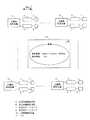
図1は、侵入者検知装置1に、送信側の漏洩伝送路5および前記送信側の漏洩伝送路5と並設され前記送信側の漏洩伝送路5からの漏洩電波を受信する受信側の漏洩伝送路6が接続され、前記受信側の漏洩伝送路6で受信した電波が変化すれば侵入者があったものと判定する侵入者検知システムであり、前記送信側の漏洩伝送路5および前記受信側の漏洩伝送路6はそれら漏洩伝送路が延在する方向に沿って点在する複数個の漏洩箇所5TH,5TH,5TH,・・・,6TH,6TH,6TH,・・・を有し、各前記漏洩箇所5TH,5TH,5TH,・・・,6TH,6TH,6TH,・・・での漏洩電波による前記受信側の受信回路であるRFモジュール12での各受信信号の状態から侵入者の侵入位置を検知する侵入位置検知機能を有している。 FIG. 1 shows a leak on a receiving side that receives a leaked radio wave from the
前記送信側の漏洩伝送路5および前記受信側の漏洩伝送路6は、例えば、市販の漏洩同軸ケーブル等を使用する。前記送信側の漏洩伝送路5および前記受信側の漏洩伝送路6の前記漏洩箇所5TH,5TH,5TH,・・・,6TH,6TH,6TH,・・・は、市販の漏洩同軸ケーブルでは数メートル間隔にその外皮を貫通する貫通スロットである。 For example, a commercially available leaky coaxial cable is used for the
ここで、侵入位置の検知概念の一例を説明する。 Here, an example of the intrusion position detection concept will be described.
前記送信側の漏洩伝送路5および前記受信側の漏洩伝送路6として市販の漏洩同軸ケーブルを使用し、前記送信側の漏洩伝送路5および前記受信側の漏洩伝送路6との間隔を数メートル離間して敷設し、図2に示すように、例えば、前記送信回路であるRFモジュール12から1個の送信パルスを送信した場合、前記送信側の漏洩伝送路5の第1番目(最初)の孔を(貫通スロット)からの漏洩電波は前記受信側の漏洩伝送路6の第1番目(最初)の孔を(貫通スロット)を介して受信され前記受信回路であるセンサーカード13に受信信号として到達するが、その到達時間は送信信号発信からΔT1後である。
同様に、前記送信回路であるRFモジュール12から1個の送信パルスを送信した場合、前記送信側の漏洩伝送路5の第2番目の孔からの漏洩電波は前記受信側の漏洩伝送路6の第2番目の孔を介して受信され前記受信回路であるセンサーカード13に受信信号として到達するが、その到達時間は送信信号発信からΔT2後である。
同様に、第3番目の孔を経た受信信号の到達時間は送信信号発信からΔT3後である。 そして、これらΔT1,ΔT2,ΔT3・・・、つまり前記到達時間(遅延時間とも言う)ΔTは、信号伝送路の長さが分かれば、信号の伝播速度が30万km/秒であることから演算により容易に求められる。
従って、前記受信回路であるセンサーカード13においては、システム構成から事前に演算した到達時間(遅延時間)ΔTのデータを保存しておくことにより、受信した実受信信号を当該保存データと照合すれば、どの孔(貫通スロット)を経由してきた受信信号であるか判別できる。
また、前記漏洩電波の存在領域に人が侵入した場合、侵入者により当該漏洩電波が、形状が変わるなど変化する。
従って、前記受信回路であるセンサーカード13が受信した信号の変化を検知すれば、前記送信側の漏洩伝送路5および前記受信側の漏洩伝送路6に沿ったどの位置に侵入したのか、検知し、報知することができる。A commercially available leaky coaxial cable is used as the
Similarly, when one transmission pulse is transmitted from the
Similarly, the arrival time of the reception signal that has passed through the third hole is ΔT3 after the transmission signal transmission. These ΔT1, ΔT2, ΔT3..., That is, the arrival time (also referred to as delay time) ΔT is calculated because the signal propagation speed is 300,000 km / sec if the length of the signal transmission path is known. More easily.
Therefore, in the
In addition, when a person enters the area where the leaked radio wave exists, the leaked radio wave changes due to the intruder changing its shape.
Therefore, if a change in the signal received by the
尤も、信号速度は極めて速いので、また、受信回路の検出動作速度との関係もあり、実際には、送信信号は単一パルスを数秒に1度程度発信するのではなく、例えば図3に例示するようなPN符号と言われているスペクトル拡散信号、例えば数万個のランダムパルス列からなるコード化信号を使えば、検知精度を上げることができる。同一のPN符号を繰返し発信してもよいし、異なるPN符号を次々に発信してもよい。PN符号自体は一般的に知られている公知の符号である。
図1に例示の侵入検知システムでPN符号を使う場合は、侵入者検知装置16は、スペクトル拡散信号を発生する送信回路であるRFモジュール12の出力で高周波の搬送波を位相変調し、送信側漏洩伝送路5に対して出力する。送信側漏洩伝送路5から出力された電波は、受信側漏洩伝送路6で前記漏洩箇所を介して受信され、受信回路であるセンサーカード13で受信される。受信回路であるセンサーカード13では、受信電波が、侵入距離に関連した参照スペクトル拡散符号と位相演算され、電界強度の変化により侵入距離に対応する侵入者検知が行われる。However, since the signal speed is extremely high and also has a relationship with the detection operation speed of the receiving circuit, the transmission signal does not actually transmit a single pulse about once every few seconds, but is illustrated in FIG. 3, for example. The detection accuracy can be improved by using a spread spectrum signal called a PN code, such as a coded signal composed of tens of thousands of random pulse trains. The same PN code may be transmitted repeatedly, or different PN codes may be transmitted one after another. The PN code itself is a publicly known code.
In the case of using a PN code in the intrusion detection system illustrated in FIG. 1, the
送信側の漏洩伝送路5および前記送信側の漏洩伝送路5と並設され前記送信側の漏洩伝送路5からの漏洩電波を受信する受信側の漏洩伝送路6を備え前記受信側の漏洩伝送路6で受信した電波が変化すれば侵入者があったものと判定する侵入者検知システムでは、発明者等の試験研究では、漏洩伝送路5,6を1500〜3000m前後敷設して漏洩伝送路5,6間への人の侵入の有無および侵入位置を、1500〜3000m前後の長距離に亘って検知できることが分かっている。 The transmission side
図4において,RFモジュール12は基準クロック発生手段1,スイッチ手段2,制御手段3,および送信スペクトル拡散信号発生手段4を有する。センサーカード13は検知手段11,参照スペクトル拡散信号発生手段9-1〜9-150,相関手段10-1〜10-150を有する事で例えば20mの精度で3000mの距離を検知範囲とする。送信用漏洩伝送路5は,送信スペクトル拡散信号を伝送する。送信用ターミネータ7は,送信スペクトル拡散信号の反射によるエラーの発生を防止する。受信用漏洩伝送路6は,送信スペクトル拡散信号を受信し伝送する。受信用ターミネータ8は,送信スペクトル拡散信号を受信した送信スペクトル拡散信号の反射によるエラーの発生を防止する。 In FIG. 4, the
図4において,RFモジュール12は基準クロック発生手段1,スイッチ手段2,制御手段3,送信スペクトル拡散信号発生手段4を有する。センサーカード13は検知手段11,参照スペクトル拡散信号発生手段9-1〜9-150,相関手段10-1〜10-150を有する事で例えば20mの精度で3000mの距離を検知範囲とする。また、前記センサーカード13は設定手段17も有し、この設定手段17は、前記各参照スペクトル拡散信号発生手段の機能を個別に機能停止させると共に前記各相関手段の機能を個別に機能停止させる機能を有している。送信用漏洩伝送路5は,送信スペクトル拡散信号を伝送する。送信用ターミネータ7は,送信スペクトル拡散信号の反射によるエラーの発生を防止する。受信用漏洩伝送路6は,送信スペクトル拡散信号を受信し伝送する。受信用ターミネータ8は,送信スペクトル拡散信号を受信した送信スペクトル拡散信号の反射によるエラーの発生を防止する。 In FIG. 4, the
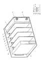
図6において,支障物検知装置とも言える侵入者検知装置16は,RFモジュール12とセンサーカード13と電源装置14を有する。 In FIG. 6, an
次に動作について説明する。 Next, the operation will be described.
センサーカード13に,150個を例えばゲートアレイなどに実装した参照スペクトル拡散信号発生手段9-1〜9-150を測定距離10m(±5m)間隔で対応した遅延時間を設定し、それぞれ拡散符号を出力する。そして,参照スペクトル拡散信号発生手段9-1〜9-150に対応した150個の相関手段10-1〜10-150を実装する。更に,センサカード13とRFモジュール12はノイズの相互干渉を避けるため、同平面上に実装し、ライトアングルタイプのインピーダンス50Ωコネクタ15により接続する。 Set the delay time corresponding to the measurement distance of 10m (± 5m) for the reference spread spectrum signal generation means 9-1 to 9-150 mounted 150 on the
RFモジュール12は,耐ノイズ性向上のためアルミ筐体で覆い、ライトアングルタイプのインピーダンス50Ωコネクタ15のみをセンサカード13側にI/Fコネクタとして露出させ接続する事により絶縁性を向上させる。 The
電源装置14は,ノイズ発生源のため,センサーカード13の横に実装し、RFモシ゛ュール12から離す。 The
これにより,複数の参照スペクトル拡散信号発生手段9-1〜9-150で侵入者の測定距離10m(±5m)間隔で対応した遅延時間の参照用拡散符号を基準クロック発生手段1から生成し,参照用拡散符号で拡散変調された参照スペクトル拡散信号を出力し,参照スペクトル拡散信号発生手段9-1〜9-150に対応した150個の相関手段10-1〜10-150で受信用漏洩伝送路6が受信した送信スペクトル拡散信号と参照スペクトル拡散信号との相関をとり,位相が一致したときに相関信号を出力し,参照スペクトル拡散信号発生手段9-1〜9-150に設定された固有の各遅延時間に対する相関信号の信号レベルの変動量が設定値以上のときに検知手段11が工場や線路等の敷地内の10m(±5m)間隔のある場所に侵入者が存在することを検知する。 As a result, a reference spread code having a delay time corresponding to an intruder measuring distance of 10 m (± 5 m) is generated from the reference clock generating means 1 by a plurality of reference spread spectrum signal generating means 9-1 to 9-150, Reference spread spectrum signal that is spread-modulated with reference spread code is output, and leaky transmission for reception is performed by 150 correlation means 10-1 to 10-150 corresponding to reference spread spectrum signal generation means 9-1 to 9-150 The transmission spectrum spread signal received by the
なお,上記実施の形態1では,測定距離10m(±5m)間隔で対応した遅延時間を設定した150個の参照スペクトル拡散信号発生手段9-1〜9-150を実装とそれに対応した150個の相関手段10-1〜10-150を実装したことで,侵入者検知装置1台で検知精度±5mを維持したまま検知距離を相関数150個×検知距離10m(±5m)=1500mにでき,経済的に優れた高範囲の侵入者検知装置16を得ることができる。 In the first embodiment, 150 reference spread spectrum signal generation means 9-1 to 9-150 having delay times corresponding to measurement distances of 10 m (± 5 m) are mounted and 150 corresponding to them are mounted. By installing the correlation means 10-1 to 10-150, the detection distance can be set to 150 correlations × detection distance 10m (± 5m) = 1500m while maintaining detection accuracy ± 5m with one intruder detection device. A high-range
実施の形態2.
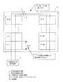
なお,上記実施の形態1では,参照スペクトル拡散信号発生手段9-1〜9-150と相関手段10-1〜10-150をそれぞれ150個実装し測定距離10m(±5m)間隔で対応した設定にすることで,検知距離1500m検知精度±5mを1台の高範囲侵入者検知装置,且つ経済的に優れた装置を実現する場合について述べたが,図7に示すように,例えば,顧客ニーズである複数の駐車スペース17-1〜17-150を有する駐車場18のような場合、測定距離10m(±5m)では隣に駐車される自動車との区別がつかないため、検知精度を細分化する必要がある。そこで、侵入者検知装置16を設置し,測定距離2.5m(±1.25m)間隔で対応した設定にすることで,複数の駐車スペース17-1〜17-148の駐車位置および自動車の出入り口17-149,17-150の台数を検知できる。Embodiment 2. FIG.
In the first embodiment, 150 reference spread spectrum signal generating means 9-1 to 9-150 and 150 correlating means 10-1 to 10-150 are mounted, and corresponding to measurement distances of 10 m (± 5 m). As described in the case of realizing a high-range intruder detection device and an economically superior device with a detection distance of 1500m and a detection accuracy of ± 5m, as shown in Fig. 7, for example, customer needs In the case of a
実施の形態3.
なお,上記実施の形態1では,参照スペクトル拡散信号発生手段9-1〜9-150と相関手段10-1〜10-150をそれぞれ150個実装し測定距離10m(±5m)間隔で対応した設定にすることで,検知距離1500m検知精度±5mを1台の高範囲侵入者検知装置,且つ経済的に優れた装置を実現する場合について述べたが,図5の配置では装置自体ある程度の大きさが必要となる。例えば,顧客ニーズである侵入者検知装置設置場所縮小化のような場合は,図8に示すように,ストレートタイプのインピーダンス50Ωコネクタ19をRFモジュール12の上部に設け,RFモジュール12の横にノイズに影響のない距離になるストレートタイプのインピーダンス50Ωコネクタ19をセンサーカード13の裏面に設けて接続することで,装置を縮小化でき,経済的に優れた侵入者検知装置を得ることができる。Embodiment 3 FIG.
In the first embodiment, 150 reference spread spectrum signal generating means 9-1 to 9-150 and 150 correlating means 10-1 to 10-150 are mounted, and corresponding to measurement distances of 10 m (± 5 m). As described above, the detection distance of 1500m and the detection accuracy of ± 5m are described for the case of realizing one high-range intruder detection device and economically superior device. Is required. For example, in the case of the intruder detection device installation site size reduction that is a customer need, as shown in FIG. 8, a straight type
実施の形態4.
なお,上記実施の形態1では,参照スペクトル拡散信号発生手段9-1〜9-150と相関手段10-1〜10-150をそれぞれ150個実装し測定距離10m(±5m)間隔で対応した設定にすることで,検知距離1500m検知精度±5mを1台の高範囲侵入者検知装置,且つ経済的に優れた装置を実現する場合について述べたが,例えば,既に顧客に納めて稼働している状態で、顧客の都合(検知範囲の増加、検知速度の向上など)で仕様追加された場合、センサカード13のみを変更した装置と入れ替える必要がある。図9に示すように,ライトアングルタイプのインピーダンス50Ωコネクタ15を実装したバックプレーン20を設け,センサカード13が外部から容易に挿抜出来る構造にすることで,設置済みの装置の仕様変更、メンテナンス性の向上を図ることが出来る。
In the first embodiment, 150 reference spread spectrum signal generating means 9-1 to 9-150 and 150 correlating means 10-1 to 10-150 are mounted, and corresponding to measurement distances of 10 m (± 5 m). We have described the case of realizing a high range intruder detection device and an economically superior device with a detection distance of 1500m and detection accuracy of ± 5m. In the state, when a specification is added due to customer convenience (increased detection range, improved detection speed, etc.), it is necessary to replace only the
実施の形態5.
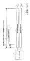
なお,上記実施の形態1では,参照スペクトル拡散信号発生手段9-1〜9-150と相関手段10-1〜10-150をそれぞれ150個実装し測定距離10m(±5m)間隔で対応した設定にすることで,検知距離1500m検知精度±5mを1台の高範囲侵入者検知装置,且つ経済的に優れた装置を実現する場合について述べたが,例えば,顧客ニーズである工場の周囲3000mのような広範囲の場合,図10に示すように,センサーカード12を接続するインピーダンス50Ωコネクタ15を2個実装したバックプレーン21を設け,RFモジュール12の横にセンサーカード13を2枚設置することで,図11に示すように,侵入者検知装置1台で検知精度±5mを維持したまま検知距離をセンサーカード2枚×相関数150個×検知距離10m(±5m)=3000mにでる。また、装置自体の信頼性向上のため、検知距離1500m検知精度±5mの仕様のまま、2枚のセンサカード13にて2重化を行い、2枚とも常に検知を行い多数決論理にて判定を行う事で誤検知率の低減が可能。また、実施の形態4でも述べたバックプレーン方式としているので、故障時もオンライン交換可能とする事でメンテナンス性向上も図れる。
In the first embodiment, 150 reference spread spectrum signal generating means 9-1 to 9-150 and 150 correlating means 10-1 to 10-150 are mounted, and corresponding to measurement distances of 10 m (± 5 m). As described above, the detection distance of 1500m and the detection accuracy of ± 5m have been described to realize one high-range intruder detection device and an economically superior device. In such a wide range, as shown in FIG. 10, a
実施の形態6.
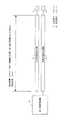
なお,上記実施の形態1では,参照スペクトル拡散信号発生手段9-1〜9-150と相関手段10-1〜10-150をそれぞれ150個実装し測定距離10m(±5m)間隔で対応した設定にすることで,検知距離1500m検知精度±5mを1台の高範囲侵入者検知装置,且つ経済的に優れた装置を実現する場合について述べたが,例えば,顧客ニーズで石油パイプラインや国境監視など100kmを超えた監視や、更に設置場所によっては電源の入力仕様が異なったり、設置環境から電源の信頼性から電源の2重化を求められる事がある。このような場合は,図12に示すように,センサーカード12を接続するインピーダンス50Ωコネクタ15を可能な限り増加したバックプレーン22を設け,RFモジュール12の横にセンサーカード13を可能な限り設置し、電源14もバックプレーン22に接続することで,図13に示すように,侵入者検知装置1台で検知精度±5mを維持したまま検知距離をセンサーカード増加数×相関数150個×検知距離10m(±5m)にでき,また、電源を2重化したり、異種電源(例えばAC100V入力タイプとDC110V入力タイプなど)をモジュールとして入れたり臨機応変に製品構成を組むことができる。
In the first embodiment, 150 reference spread spectrum signal generating means 9-1 to 9-150 and 150 correlating means 10-1 to 10-150 are mounted, and corresponding to measurement distances of 10 m (± 5 m). As described above, we have described the case of realizing a high range intruder detection device and economically superior device with a detection distance of 1500m detection accuracy ± 5m. For example, oil pipelines and border monitoring according to customer needs Depending on the installation location, the input specifications of the power supply may differ, or the power supply may be duplicated due to the reliability of the power supply from the installation environment. In such a case, as shown in FIG. 12, a
1 基準クロック発生手段、
2 スイッチ手段、
3 制御手段、
4 送信スペクトル拡散信号発生手段、
5 送信用漏洩伝送路、
5c 送信用漏洩伝送路とのコネクタ、
5TH 漏洩箇所(孔)、
6 受信用漏洩伝送路、
6c 受信用漏洩伝送路とのコネクタ、
6TH 漏洩箇所(孔)、
7 送信用ターミネータ、
8 受信用ターミネータ、
9-1〜9-150 参照スペクトル拡散信号発生手段、
10-1〜10-150 相関手段、
11 検知手段、
12 RFモジュール、
13 センサーカード、
14 電源装置、
15 コネクタ、
16 侵入者検知装置、
17 設定手段、
17-1〜17-150 駐車スペース、
18 駐車場、
19 コネクタ、
20 バックプレーン、
21 バックプレーン、
22 バックプレーン。1 Reference clock generation means,
2 switch means,
3 Control means,
4 Transmission spread spectrum signal generation means,
5 Leakage transmission line for transmission,
5c Connector for leaky transmission line for transmission,
5TH Leakage point (hole),
6 Leakage transmission line for reception,
6c Connector for receiving leaky transmission line,
6TH Leakage point (hole),
7 Transmission terminator,
8 Receive terminator,
9-1 to 9-150 Reference spread spectrum signal generating means,
10-1 to 10-150 correlation means,
11 detection means,
12 RF modules,
13 Sensor card,
14 power supply,
15 connectors,
16 Intruder detection device,
17 Setting means,
17-1 to 17-150 parking space,
18 Parking,
19 connectors,
20 backplane,
21 backplane,
22 Backplane.
Claims (14)
Translated fromJapanese検知手段に必要な測定距離10m(漏洩箇所から±5m)に対応した参照スペクトル拡散信号発生手段と相関手段とを150個実装するセンサーカードとし、当該センサーカードを2枚実装することで、検知距離3000m、検知精度±5mの検知機能を有していることを特徴とする侵入者検知装置。The intruder detection device according to any one of claims 1 to 11, wherein the sensor card is
A sensor card with 150 reference spread spectrum signal generation means and correlation means corresponding to a measurement distance of 10m (± 5m from the leaked location) required for the detection means, and the detection distance by mounting two such sensor cards An intruder detection device characterized by having a detection function of 3000m and detection accuracy of ± 5m.
Priority Applications (2)
| Application Number | Priority Date | Filing Date | Title |
|---|---|---|---|
| JP2005378783AJP4667237B2 (en) | 2005-12-28 | 2005-12-28 | Intruder detection device |
| US11/516,568US7675416B2 (en) | 2005-12-28 | 2006-09-07 | Intruder detection device |
Applications Claiming Priority (1)
| Application Number | Priority Date | Filing Date | Title |
|---|---|---|---|
| JP2005378783AJP4667237B2 (en) | 2005-12-28 | 2005-12-28 | Intruder detection device |
Publications (2)
| Publication Number | Publication Date |
|---|---|
| JP2007179401A JP2007179401A (en) | 2007-07-12 |
| JP4667237B2true JP4667237B2 (en) | 2011-04-06 |
Family
ID=38223765
Family Applications (1)
| Application Number | Title | Priority Date | Filing Date |
|---|---|---|---|
| JP2005378783AActiveJP4667237B2 (en) | 2005-12-28 | 2005-12-28 | Intruder detection device |
Country Status (2)
| Country | Link |
|---|---|
| US (1) | US7675416B2 (en) |
| JP (1) | JP4667237B2 (en) |
Families Citing this family (9)
| Publication number | Priority date | Publication date | Assignee | Title |
|---|---|---|---|---|
| US7804441B1 (en)* | 2007-07-13 | 2010-09-28 | The United States Of America As Represented By The Secretary Of The Navy | Detection of concealed object by standing waves |
| JP4573866B2 (en) | 2007-12-17 | 2010-11-04 | 三菱電機株式会社 | Intrusion detection system |
| US8387142B2 (en)* | 2008-08-21 | 2013-02-26 | At&T Mobility Ii Llc | System and method for radio frequency intrusion detection |
| FR2936891B1 (en)* | 2008-10-07 | 2013-03-15 | Bubendorff | DEVICE FOR DETECTING THE PRESENCE OF AN OBJECT OR A LIVING BEING |
| JP5116790B2 (en) | 2010-03-23 | 2013-01-09 | 三菱電機株式会社 | Intrusion detection system and sensor device thereof |
| JP5351211B2 (en)* | 2011-06-14 | 2013-11-27 | 三菱電機株式会社 | Intrusion detection system and intrusion detection device |
| JP5874412B2 (en) | 2012-01-30 | 2016-03-02 | セイコーエプソン株式会社 | Robot, approach detection method |
| DE102014200898B4 (en)* | 2014-01-20 | 2016-01-14 | Siemens Aktiengesellschaft | Method and device for detecting an occupancy state of a parking lot |
| CN107437316B (en)* | 2016-05-27 | 2022-11-08 | 成都华立安安防科技有限公司 | Biological induction windowsill and using method thereof |
Family Cites Families (25)
| Publication number | Priority date | Publication date | Assignee | Title |
|---|---|---|---|---|
| CA1280488C (en)* | 1986-11-06 | 1991-02-19 | Control Data Canada Limited | Perimeter intrusion detection system with block ranging capability |
| JP3107437B2 (en) | 1991-12-17 | 2000-11-06 | クラリオン株式会社 | Security device |
| CA2165384C (en)* | 1995-12-15 | 2008-04-01 | Andre Gagnon | Open transmission line intrusion detection system using frequency spectrum analysis |
| JP3426068B2 (en) | 1995-12-20 | 2003-07-14 | 三菱電機株式会社 | TV camera switching monitoring method |
| JPH09274077A (en) | 1996-04-04 | 1997-10-21 | Maruyasu Kogyo Kk | Sensor for movement of body |
| JPH1095338A (en) | 1996-09-25 | 1998-04-14 | Hitachi Cable Ltd | Pseudo radar type obstacle detection device |
| US5914655A (en)* | 1996-10-17 | 1999-06-22 | Senstar-Stellar Corporation | Self-compensating intruder detector system |
| CA2207119A1 (en)* | 1997-06-06 | 1998-12-06 | Andre Gagnon | Intrusion detection system using quiet signal band detection |
| US6271754B1 (en)* | 1999-07-01 | 2001-08-07 | Microlynx Systems, Ltd. | Method and system for detecting intrusions into a particular region |
| US6204772B1 (en)* | 1999-12-16 | 2001-03-20 | Caterpillar Inc. | Method and apparatus for monitoring the position of a machine |
| JP2001243573A (en)* | 2000-02-28 | 2001-09-07 | Atsumi Electric Co Ltd | Security system |
| US6424259B1 (en)* | 2000-06-27 | 2002-07-23 | Auratek Security Inc. | Intruder/escapee detection system and method using a distributed antenna and an array of discrete antennas |
| US6577236B2 (en)* | 2000-09-05 | 2003-06-10 | Robert Keith Harman | FM CW cable guided intrusion detection radar |
| JP2002171513A (en)* | 2000-11-29 | 2002-06-14 | Animakkusu:Kk | Automatic detector by monitor cameras |
| JP2002170176A (en)* | 2000-12-01 | 2002-06-14 | Atsumi Electric Co Ltd | Method of setting use of input / output channels and system equipment |
| US6664894B2 (en)* | 2001-02-16 | 2003-12-16 | General Phosphorix Llc | Perimeter system for detecting intruders |
| US7019648B2 (en)* | 2001-10-17 | 2006-03-28 | Auratek Security Inc. | Intruder/escapee detection system |
| JP4138386B2 (en)* | 2002-07-23 | 2008-08-27 | 三菱電機株式会社 | Mobile communication system |
| JP4097131B2 (en)* | 2002-09-26 | 2008-06-11 | 三菱電機株式会社 | Obstacle detection device |
| JP4046274B2 (en)* | 2002-10-02 | 2008-02-13 | 三菱電機株式会社 | Intruder and obstacle detection device |
| JP4020194B2 (en)* | 2002-11-08 | 2007-12-12 | 三菱電機株式会社 | Obstacle detection device |
| JP4248916B2 (en) | 2003-04-10 | 2009-04-02 | 三菱電機株式会社 | Obstacle detection device |
| JP4046638B2 (en)* | 2003-04-14 | 2008-02-13 | 三菱電機株式会社 | Obstacle detection device |
| JP2005025479A (en)* | 2003-07-01 | 2005-01-27 | Keyence Corp | Safety relay system and control method for safety relay |
| US7069160B2 (en)* | 2004-08-31 | 2006-06-27 | Cecil Kenneth B | Intrusion detection system and method thereof |
- 2005
- 2005-12-28JPJP2005378783Apatent/JP4667237B2/enactiveActive
- 2006
- 2006-09-07USUS11/516,568patent/US7675416B2/ennot_activeExpired - Fee Related
Also Published As
| Publication number | Publication date |
|---|---|
| JP2007179401A (en) | 2007-07-12 |
| US20070152818A1 (en) | 2007-07-05 |
| US7675416B2 (en) | 2010-03-09 |
Similar Documents
| Publication | Publication Date | Title |
|---|---|---|
| US7675416B2 (en) | Intruder detection device | |
| US9423443B2 (en) | System and method of detecting and locating intermittent and other faults | |
| US8022708B2 (en) | Fiber optic fault detection system and method for underground power lines | |
| KR101932892B1 (en) | Multi leak and fire sensing apparatus | |
| CN103344880A (en) | Leaky cable/antenna feeder real-time monitoring apparatus and working method thereof | |
| CN102879718A (en) | Wired-loop-based entire-station monitoring and positioning system and positioning method for partial discharge | |
| EP3855207A1 (en) | A radar system and a diagnostic method thereof | |
| JP5528313B2 (en) | Intrusion detection system | |
| JP2012202946A (en) | Shielded room monitoring system | |
| CN117590284A (en) | Embedded cable self-diagnosis method and system | |
| ATE211256T1 (en) | DEVICE AND METHOD FOR DETECTING OIL ON WATER | |
| KR20140098742A (en) | Method and device for synchronizing an apparatus connected to a communication network | |
| JP2007189521A (en) | Intrusion detection system | |
| CN102901912A (en) | Local discharge monitoring method for multiple intensively arranged power equipment | |
| US9464888B2 (en) | Method and apparatus for sensing boundary between materials | |
| CN209432061U (en) | Displacement monitoring system of GIS equipment and GIS equipment | |
| JP5116790B2 (en) | Intrusion detection system and sensor device thereof | |
| JP3966779B2 (en) | Train line management apparatus by wireless transmission and train line management method by wireless transmission | |
| KR960012800A (en) | Wiring line failure remote monitoring method and device | |
| CN203368489U (en) | Real-time monitoring device for leakage cable/antenna feeder | |
| JP5059931B2 (en) | Intrusion detection system | |
| CN117129727A (en) | Accurate positioning system for electric potential theft of line | |
| KR0160805B1 (en) | Optical connector for trouble tracking in the catv system | |
| RU1781504C (en) | Device for detecting damages of fluid-supply pipe system | |
| CN202770957U (en) | Synchronous monitoring system for partial discharge of multiple electric power devices of transformer substation |
Legal Events
| Date | Code | Title | Description |
|---|---|---|---|
| A621 | Written request for application examination | Free format text:JAPANESE INTERMEDIATE CODE: A621 Effective date:20080110 | |
| A977 | Report on retrieval | Free format text:JAPANESE INTERMEDIATE CODE: A971007 Effective date:20100902 | |
| A131 | Notification of reasons for refusal | Free format text:JAPANESE INTERMEDIATE CODE: A131 Effective date:20100914 | |
| A521 | Request for written amendment filed | Free format text:JAPANESE INTERMEDIATE CODE: A523 Effective date:20101025 | |
| TRDD | Decision of grant or rejection written | ||
| A01 | Written decision to grant a patent or to grant a registration (utility model) | Free format text:JAPANESE INTERMEDIATE CODE: A01 Effective date:20110105 | |
| A01 | Written decision to grant a patent or to grant a registration (utility model) | Free format text:JAPANESE INTERMEDIATE CODE: A01 | |
| A61 | First payment of annual fees (during grant procedure) | Free format text:JAPANESE INTERMEDIATE CODE: A61 Effective date:20110111 | |
| FPAY | Renewal fee payment (event date is renewal date of database) | Free format text:PAYMENT UNTIL: 20140121 Year of fee payment:3 | |
| R151 | Written notification of patent or utility model registration | Ref document number:4667237 Country of ref document:JP Free format text:JAPANESE INTERMEDIATE CODE: R151 | |
| FPAY | Renewal fee payment (event date is renewal date of database) | Free format text:PAYMENT UNTIL: 20140121 Year of fee payment:3 | |
| R250 | Receipt of annual fees | Free format text:JAPANESE INTERMEDIATE CODE: R250 | |
| R250 | Receipt of annual fees | Free format text:JAPANESE INTERMEDIATE CODE: R250 | |
| R250 | Receipt of annual fees | Free format text:JAPANESE INTERMEDIATE CODE: R250 | |
| R250 | Receipt of annual fees | Free format text:JAPANESE INTERMEDIATE CODE: R250 | |
| R250 | Receipt of annual fees | Free format text:JAPANESE INTERMEDIATE CODE: R250 | |
| R250 | Receipt of annual fees | Free format text:JAPANESE INTERMEDIATE CODE: R250 | |
| R250 | Receipt of annual fees | Free format text:JAPANESE INTERMEDIATE CODE: R250 | |
| R250 | Receipt of annual fees | Free format text:JAPANESE INTERMEDIATE CODE: R250 | |
| R250 | Receipt of annual fees | Free format text:JAPANESE INTERMEDIATE CODE: R250 |