JP4666740B2 - Semiconductor manufacturing apparatus, substrate surface processing method, and plasma product adhesion state observation method - Google Patents
Semiconductor manufacturing apparatus, substrate surface processing method, and plasma product adhesion state observation methodDownload PDFInfo
- Publication number
- JP4666740B2 JP4666740B2JP2000307237AJP2000307237AJP4666740B2JP 4666740 B2JP4666740 B2JP 4666740B2JP 2000307237 AJP2000307237 AJP 2000307237AJP 2000307237 AJP2000307237 AJP 2000307237AJP 4666740 B2JP4666740 B2JP 4666740B2
- Authority
- JP
- Japan
- Prior art keywords
- bias voltage
- plasma
- electromagnetic wave
- predetermined range
- power
- Prior art date
- Legal status (The legal status is an assumption and is not a legal conclusion. Google has not performed a legal analysis and makes no representation as to the accuracy of the status listed.)
- Expired - Fee Related
Links
Images


Classifications
- H—ELECTRICITY
- H01—ELECTRIC ELEMENTS
- H01J—ELECTRIC DISCHARGE TUBES OR DISCHARGE LAMPS
- H01J37/00—Discharge tubes with provision for introducing objects or material to be exposed to the discharge, e.g. for the purpose of examination or processing thereof
- H01J37/32—Gas-filled discharge tubes
- H01J37/32431—Constructional details of the reactor
- H01J37/32623—Mechanical discharge control means
- H—ELECTRICITY
- H01—ELECTRIC ELEMENTS
- H01J—ELECTRIC DISCHARGE TUBES OR DISCHARGE LAMPS
- H01J37/00—Discharge tubes with provision for introducing objects or material to be exposed to the discharge, e.g. for the purpose of examination or processing thereof
- H01J37/32—Gas-filled discharge tubes
- H01J37/32431—Constructional details of the reactor
- H01J37/3266—Magnetic control means
- H01J37/32678—Electron cyclotron resonance
- H—ELECTRICITY
- H01—ELECTRIC ELEMENTS
- H01J—ELECTRIC DISCHARGE TUBES OR DISCHARGE LAMPS
- H01J37/00—Discharge tubes with provision for introducing objects or material to be exposed to the discharge, e.g. for the purpose of examination or processing thereof
- H01J37/32—Gas-filled discharge tubes
- H01J37/32431—Constructional details of the reactor
- H01J37/32697—Electrostatic control
- H01J37/32706—Polarising the substrate
- H—ELECTRICITY
- H01—ELECTRIC ELEMENTS
- H01L—SEMICONDUCTOR DEVICES NOT COVERED BY CLASS H10
- H01L21/00—Processes or apparatus adapted for the manufacture or treatment of semiconductor or solid state devices or of parts thereof
- H01L21/02—Manufacture or treatment of semiconductor devices or of parts thereof
- H01L21/04—Manufacture or treatment of semiconductor devices or of parts thereof the devices having potential barriers, e.g. a PN junction, depletion layer or carrier concentration layer
- H01L21/18—Manufacture or treatment of semiconductor devices or of parts thereof the devices having potential barriers, e.g. a PN junction, depletion layer or carrier concentration layer the devices having semiconductor bodies comprising elements of Group IV of the Periodic Table or AIIIBV compounds with or without impurities, e.g. doping materials
- H01L21/30—Treatment of semiconductor bodies using processes or apparatus not provided for in groups H01L21/20 - H01L21/26
- H01L21/302—Treatment of semiconductor bodies using processes or apparatus not provided for in groups H01L21/20 - H01L21/26 to change their surface-physical characteristics or shape, e.g. etching, polishing, cutting
- H01L21/306—Chemical or electrical treatment, e.g. electrolytic etching
- H01L21/3065—Plasma etching; Reactive-ion etching
- H—ELECTRICITY
- H01—ELECTRIC ELEMENTS
- H01L—SEMICONDUCTOR DEVICES NOT COVERED BY CLASS H10
- H01L21/00—Processes or apparatus adapted for the manufacture or treatment of semiconductor or solid state devices or of parts thereof
- H01L21/02—Manufacture or treatment of semiconductor devices or of parts thereof
- H01L21/04—Manufacture or treatment of semiconductor devices or of parts thereof the devices having potential barriers, e.g. a PN junction, depletion layer or carrier concentration layer
- H01L21/18—Manufacture or treatment of semiconductor devices or of parts thereof the devices having potential barriers, e.g. a PN junction, depletion layer or carrier concentration layer the devices having semiconductor bodies comprising elements of Group IV of the Periodic Table or AIIIBV compounds with or without impurities, e.g. doping materials
- H01L21/30—Treatment of semiconductor bodies using processes or apparatus not provided for in groups H01L21/20 - H01L21/26
- H01L21/31—Treatment of semiconductor bodies using processes or apparatus not provided for in groups H01L21/20 - H01L21/26 to form insulating layers thereon, e.g. for masking or by using photolithographic techniques; After treatment of these layers; Selection of materials for these layers
- H01L21/3105—After-treatment
- H01L21/311—Etching the insulating layers by chemical or physical means
- H01L21/31105—Etching inorganic layers
- H01L21/31111—Etching inorganic layers by chemical means
- H01L21/31116—Etching inorganic layers by chemical means by dry-etching
Landscapes
- Physics & Mathematics (AREA)
- Engineering & Computer Science (AREA)
- Plasma & Fusion (AREA)
- Chemical & Material Sciences (AREA)
- Analytical Chemistry (AREA)
- Plasma Technology (AREA)
- Drying Of Semiconductors (AREA)
Description
Translated fromJapanese【0001】
【発明の属する技術分野】
本発明は、半導体製造装置、被処理基板表面の処理方法およびプラズマ生成物の付着状態の観察方法に関するものである。
【0002】
【従来の技術】
従来、微細加工用のプラズマエッチング装置は、被エッチング膜に合わせたプロセスガスをチャンバ内に導入し、マイクロ波や、13.56MHz、27MHzあるいは60MHz等の高周波でプラズマを生成し、その一方でウェハが設置される電極にバイアス電圧を印加することにより、プラズマからウェハに入射するイオンエネルギを制御しつつ、被エッチング膜の異方性加工を実現してきた。これらの代表的な放電形式として、ECR(Electron Cyclotron Resonance)、ICP(Inductive Coupled Plasma)があり、低圧で高密度のプラズマを得ることが出来る。
【0003】
以下に、ECR励起を利用した従来のプラズマエッチング装置を説明する。
図5は、ECR励起を利用したプラズマエッチング装置100のチャンバ構造を模式的に示した断面図である。図中参照番号21はチャンバを示している。チャンバ21の内壁は、石英内筒21aで覆われ絶縁されているため、余剰の電荷を吸収するためアース電極21bが、設置されている。チャンバ21の上部には空洞共振部22が形成され、空洞共振部22は、例えば石英天板23で封止されている。石英天板23の下部に石英天板に平行にガスシャワープレート24が配設されており、石英天板23とガスシャワープレート24との間にはわずかに隙間がある。この隙間にガス導入管(図示せず)が接続され、ガス導入管よりプロセスガスが導入される。
【0004】
空洞共振部22には導波管26が接続され、導波管26の他端部は第1の電磁波であるマイクロ波を供給する第1の電磁波の供給源(マイクロ波供給源)25に接続されている。導波管26の一端部、空洞共振部22、およびチャンバ21の一部の周囲にはこれらと同心状にコイル27a、27b、27cが配設されており、コイル27a、27b、27cには直流電源(図示せず)が接続されている。これらの空洞共振部22、マイクロ波を供給するマイクロ波供給源25、導波管、コイル27a、27b、27等を含んで、プラズマ源20が構成されている。
【0005】
ガスシャワープレート24は、チャンバ21上部に連接されており、ガスシャワープレート24には同心状に小孔が形成されている。図示しないガス導入管から供給された各種のプロセスガスが、ガスシャワープレート24からチャンバ21内に供給される。そして、可変コンダクタンスバルブ32を介して真空ポンプ34で排気を行うことにより、チャンバ21内の圧力が制御される。チャンバ21の中央部には、下部電極28が配設され、下部電極28の上部が被処理基板を保持できる試料台となっている。下部電極28には第2の電磁波である高周波(RF) を印加してバイアス電圧を発生させるための高周波(RF) 電源29が接続され、この高周波電源29は接地されている。この高周波電源29によりバイアス源が構成される。
【0006】
このように構成されたプラズマエッチング装置100を用いて被処理基板をエッチングする場合、まず、チャンバ21を減圧し、真空にしたチャンバ21内に図示しないガス導入管よりプロセスガスを導入し、圧力を所定値に制御する。そしてコイル27a、27b、27cに直流電流を供給して空洞共振部22に磁界を形成すると共に、マイクロ波供給源25より、例えば2.45GHzのマイクロ波を、導波管26を介して空洞共振部22に導入する。この磁界とマイクロ波との相互作用によりプラズマが形成される。そして、下部電極28に高周波電源29より高周波電力を印加してバイアス電圧を発生させ、下部電極28上部の試料台に保持される被処理基板に、プラズマ中の荷電粒子(イオン)や中性活性粒子(ラジカル)を入射して、エッチングが行われる。このイオンの入射エネルギーは、高周波電源29により下部電極28に発生させたバイアス電圧により制御される。
【0007】
【発明が解決しようとする課題】
ところで、このようなプラズマエッチング装置においても、半導体加工の微細化に伴い、エッチングプロセスに対する要求(例えば、低マイクロローディング効果、高選択性、高再現性、高精度加工)はますます厳しくなっている。しかし、これらの要求項目はトレードオフの関係が複雑に絡んでおり、全てを満たす安定領域は極めて狭い。そして、この安定領域でさえ、エッチング生成物の蓄積により経時的にシフトしてしまうのが現状である。
【0008】
例えば、上述のプラズマエッチング装置100での酸化膜エッチングにおいては、アース電極21bの表面は、プラズマからのイオン衝撃やエッチング生成物の付着の影響を受けるため、アース能力が経時的に低下していく。その結果、次第にチャンバ21内のイオン密度が増加し、バイアスとして一定電力を印加する下部電極28のバイアス電圧のピークツウピーク電圧(以下、単にVppという)は低下する。Vppの低下は被処理基板であるウェハに入射するイオンエネルギを低下させるため、マイクロローディング効果(狭スペースのエッチレート低下)が増長される。
【0009】
まず、上述のプラズマエッチング装置100におけるホール加工では、基板やシリサイド層、あるいはSAC構造では窒化膜に対して、高選択性を確保する必要性から、C4F8のようなC/F比の高いガスを用い、エッチングがフルオロカーボン膜のデポより若干優勢となるところでプロセスを構築している。このため、イオンエネルギが低下すると、エッチングよりデポが優勢となりエッチングストップが生じることがある。
【0010】
また、素子分離(LOCOS形成)のための窒化膜エッチングやゲートエッチングでは、下地の薄い酸化膜や酸窒化膜に対して選択性よくエッチングすることが要求される。ここでも、アース能力が低下すれば、マイクロローディング効果が増長される。
【0011】
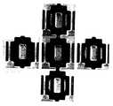
図6は、窒化膜エッチングにおいて、マイクロローディング効果によりエッチング残りが発生した事例を示す。図6は、上より順に、ウェハの同一面内のトップ、レフト、センタ、ライト、ボトムを撮影したものである。全て同じアクティブパターンを示している。白い部分がエッチングされた部分である。例えばセンタの中央には大きくエッチングされた白い部分が見え、その両脇は黒く見える。この黒い部分には、本来ならボトムでは明らかに見える中央両脇の細長いスリットがエッチングされている部分であるが、マイクロローディング効果によりエッチングが十分にされなかったため、窒化膜が残ってしまい黒く見えている。
このように、Vppの低下はウェハに入射するイオンエネルギを低下させ、狭スペースのエッチレート低下が増長される。
【0012】
メンテナンスによりアース電極を交換することでアース能力は回復するが、パーツの個体差等によりそれまで以上にアース能力が回復した場合には、チャンバ内のプラズマのイオン密度が低下し、設定電力を維持しようと下部電極のVppが増加する。この結果、入射イオンエネルギが増大し、下地選択性が悪化する。
【0013】
図7は、アース電極の交換によりVppが増加し窒化膜エッチングにおいて下地酸化膜抜けが発生した事例を示す。図7は、上より順に、ウェハの同一面内のトップ、レフト、センタ、ライト、ボトムを撮影したものである。トップ、レフト、センタ、ライト、ボトム、それぞれ中央にレジストに覆われて黒く見える部分があるが、その両脇に虫食い状の孔が見える。これらは、パッド酸化膜を破ってシリコン基板までエッチングが進んでしまった部分である。
【0014】
上述の図6、7により具体的に示す事例は、長期的な変動の結果を示しているが、短期的な変動としてロット内のウェハ間やロット間の変動が存在する。
半導体製造装置の歩留まり低下の一因に、チャンバ内付着物に起因する異物の落下がある。これを防ぐために、定期的なプラズマクリーニングが実施される。しかし、プラズマクリーニング直後のアース電極表面は清浄であるが、ウェハ処理の進行と共に付着物の影響等でアース能力は低下し、上述のようなマイクロローディング効果や下地酸化膜抜けといった大きなトラブルに至らないまでも、微細加工の再現性のレベル(寸法や下地選択性のシフト等)について影響が出てくる。
【0015】
プロセス中に、ウェハに入射するイオンのエネルギが変動するという上述の従来技術の問題に対し、これまで、下部電極に高周波(RF)電力を供給する高周波(RF)電源の電力を制御することにより、Vppを一定の所定値にして、エッチングレートを制御する方法(特開平8−199378号公報)等が提案されている。しかし、高周波電力をVppが一定になるように制御を行うと、処理状態によっては、高周波電力の過剰供給または供給不足になってしまい、エッチング性能、特に形状制御が出来なくなるという問題がある。
【0016】
【発明が解決しようとする課題】
本発明の目的は、常に一定のエッチングレートでプロセスを維持することができ、低マイクロローディング効果、高下地選択性、高再現性、高精度加工を可能とする半導体製造装置、被処理基板表面の処理方法、およびこれらを可能とするために半導体製造装置内におけるプラズマ生成物の付着状態を観察する方法を提供することである。
【0017】
【課題を解決するための手段】
一般的に、プロセス中にイオン密度が変動しウェハへの入射イオンエネルギが変動する結果起きる、マイクロローディング効果の増大、下地選択性の悪化、微細加工の再現性の低下等の従来技術の問題は、チャンバ壁またはアース電極とプラズマとの相互作用の経時変化にある。
【0018】
本発明者は、この経時変化は、直接的にはチャンバ壁またはアース電極に流れるアース電流を測定することで監視することができ、間接的には、被処理基板を載置する下部電極側に印加されるバイアス電圧を測定することで監視することができることを知見し、さらに、チャンバ内壁またはアース電極とプラズマとの相互作用の経時変化は避けがたいものであるものの、バイアス電圧を監視し、その値が所定範囲に保持されるよう、マイクロ波を供給する電磁波(プラズマ波)供給源の電力を制御することにより、チャンバ内のプラズマ中の荷電粒子(イオン)密度を補償することが可能であり、それにより、従来技術の問題を解決し、上記目的を達成できることを知見し、本発明を完成した。
【0020】
すなわち、本発明は、プラズマ中の荷電粒子を、バイアス電圧によって制御されたエネルギで被処理基板表面に入射させて、被処理基板表面を処理するプラズマエッチング装置であって、
チャンバ内のガス雰囲気に、マイクロ波供給源から供給される第1の電磁波を印加して前記プラズマを生成するプラズマ源と、
前記被処理基板に前記プラズマ中の荷電粒子を入射させるために高周波電源から供給される第2の電磁波を印加して前記バイアス電圧を発生させるバイアス源と、
前記バイアス電圧を測定する第1の測定手段と、
前記プラズマからこのプラズマが接する前記チャンバ内壁もしくはアース電極に流れるアース電流を測定する第2の測定手段と、
前記第1の測定手段によって測定された前記バイアス電圧と前記第2の測定手段による前記アース電流の測定結果に基づいて、前記マイクロ波供給源からの第1の電磁波の電力と前記高周波電源からの第2の電磁波の電力とのいずれかを制御することによって、前記バイアス電圧を前記所定範囲内に保持する制御手段とを有することを特徴とするプラズマエッチング装置を提供する。
【0022】
また、本発明は、チャンバ内のガス雰囲気に、マイクロ波供給源から供給される第1の電磁波を印加してプラズマを生成すると共に、高周波電源から供給される第2の電磁波を印加してバイアス電圧を発生させ、被処理基板の表面に、前記プラズマ中の荷電粒子を、前記バイアス電圧によって制御されたエネルギで入射させ、被処理基板の表面を処理するプラズマエッチング方法であって、
この処理の少なくとも一時期に、前記バイアス電圧を測定すると共に、
前記プラズマからこのプラズマが接する前記チャンバ内壁もしくはアース電極に流れるアース電流を測定し、測定された前記バイアス電圧と該アース電流の測定結果に基づいて、前記マイクロ波供給源からの第1の電磁波の電力と前記高周波電源からの第2の電磁波の電力とのいずれかを制御して、前記バイアス電圧を前記所定範囲内に保持することを特徴とするプラズマエッチング方法を提供する。
【0023】
前記第1の電磁波の電力の制御によって、前記バイアス電圧を前記所定範囲内に保持することができない時に、さらに、前記第2の電磁波の電力を制御して前記バイアス電圧を前記所定範囲内に保持するのが好ましい。
【0024】
また、本発明は、チャンバ内のガス雰囲気に、マイクロ波供給源から供給される第1の電磁波を印加してプラズマを生成すると共に、高周波電源から供給される第2の電磁波を印加してバイアス電圧を発生させ、被処理基板の表面に、前記プラズマ中の荷電粒子を、前記バイアス電圧によって制御されたエネルギで入射させ、被処理基板の表面を処理するプラズマエッチング方法であって、
この処理の少なくとも一時期に、前記バイアス電圧を測定すると共に、前記プラズマからこのプラズマが接する前記チャンバ内壁もしくはアース電極に流れるアース電流を測定し、測定された前記バイアス電圧が第1の所定範囲から逸脱し、かつ、測定された前記アース電流が第2の所定範囲から逸脱している場合に、前記第1の電磁波の電力を制御して、前記バイアス電圧を前記第1の所定範囲内に保持することを特徴とするプラズマエッチング方法を提供する。
【0025】
さらに、本発明は、チャンバ内のプラズマ生成物の付着状態を観察する方法であって、前記チャンバ内のガス雰囲気に電磁波を印加してプラズマを生成すると共に、前記プラズマからこのプラズマが接する前記チャンバ内壁もしくはアース電極に流れるアース電流を測定することによって、前記チャンバ内壁もしくは前記アース電極へのプラズマ生成物の付着状態を観察する方法を提供する。
【0026】
【発明の実施の形態】
本発明にかかる半導体製造装置、被処理基板表面の処理方法およびプラズマ生成物の付着状態を観察する方法を添付の図面に示す好適実施例に基づいて以下に詳細に説明する。
図1は、本発明の被処理基板表面の処理方法およびプラズマ生成物の付着状態を観察する方法を実施する本発明の半導体製造装置の一実施例にかかるECRプラズマエッチング装置である。なお、本発明は図示例に限定されないのはもちろんである。
図1に示すプラズマエッチング装置10は、図5に示すプラズマエッチング装置100と、電流測定手段30aおよび電圧測定手段30bを含む測定部30ならびに制御部31を備えている点を除いては、同一の構成を有しているので、同一の構成要素には同一の参照符号を付し、その詳細な説明は省略し、主として相違点について説明する。
【0027】
図1に示すプラズマエッチング装置10は、測定部30を有し、この測定部30はプラズマ源20により供給されるプラズマからこのプラズマが接するアース電極21bに流れるアース電流を測定する電流測定手段30aと、高周波(RF)電源29により下部電極28に印加された電磁波により発生するバイアス電圧を測定する電圧測定手段30bとの両方を備える。しかし、本発明はこれに限定されず、測定部30は、少なくとも電圧測定手段30bを備えていればよい。従って、本発明においては、測定部30は、少なくともバイアス電圧を測定するものであればよい。
【0028】
アース電極21bには、アース電流を測定するための電流測定手段30aの一端部が接続されており、電流測定手段30aの他端部は接地されている。また、電流測定手段30aは、制御部31に接続されている。
下部電極28には、バイアス電圧を測定する電圧測定手段30bの一端部が接続されており、電圧測定手段30bの他端部は接地されている。また、電圧測定手段30bは、制御部31に接続されている。電圧測定手段30bは、バイアス電圧のピーク電圧(Vpp)を測定するものであってもよい。
【0029】
制御部31は、導波管26や空洞共振部22等にマイクロ波を供給するマイクロ波供給源25に接続されている。
アース電流とバイアス電圧とについて、予め、基準アース電流値を中心値として含む許容される所定範囲と、基準バイアス電圧値を中心値として含む許容される所定範囲が設定されている。電圧測定手段30bにより測定されたバイアス電圧に対応する入力信号が、もしくはさらに、電流測定手段30aにより測定されたアース電流に対応する入力信号が、制御部31に入力され、測定されたバイアス電圧は所定範囲に入っているかが判断され、これに応じてマイクロ波供給源25の供給電力量の増減を指示する信号がマイクロ波供給源25に入力される。
すなわち、測定されたバイアス電圧が、所定範囲の上限を上回る場合にマイクロ波供給源25の電力を増大させ、所定範囲の下限を下回る場合にマイクロ波供給源25の電力を減少させ、バイアス電圧を所定範囲内に保持する。
これによりプラズマエッチング装置10では、バイアス電圧を所定範囲内に保持することができる。
【0030】
図1のプラズマエッチング装置10では、制御部31が下部電極に高周波を印加してバイアス電圧を発生させる高周波電源29にも接続されている。これにより、制御部31に入力されるバイアス電圧の測定値に基づいて、マイクロ波供給源25の電力の増減を指示する信号をマイクロ波供給源25に入力するのみではなく、高周波電源29の電力の増減を指示する信号を高周波電源29に入力することもできる。
【0031】
例えば、電圧測定手段30bにより測定されたバイアス電圧が所定範囲の上限を上回っている場合であっても、高周波電力を制御することが適切であると判断した場合には、高周波電源29の電力を減少させるよう、制御部31から高周波電源29に信号が入力される。同様に、バイアス電圧が所定範囲の下限を下回っている場合であっても、高周波電力を制御することが適切であると判断した場合には、高周波電源29の電力を増大させるよう、制御部31から高周波電源29に信号が入力される。これにより、バイアス電圧を所定範囲内に保持することができる。
このように高周波電力を制御することが適切であるか否かは、例えば、電流測定手段30aにより測定されたアース電流が所定範囲内であるかどうかによって判断される。
【0032】
図1に示すプラズマエッチング装置10においては、制御部31は、導波管26や空洞共振部22等にマイクロ波を供給するマイクロ波供給源25に接続され、加えて、下部電極28に高周波を印加してバイアス電圧を発生する高周波(RF)電源29に接続されているが、本発明はこれに限定されず、制御部31はマイクロ波供給源25のみに接続されていても良い。従って、本発明においては、制御部31は、マイクロ波供給源25の電力および高周波電源29の電力の両方を制御するものでもよく、また、マイクロ波供給源25の電力のみを制御するものでもよい。
【0033】
本発明の半導体製造装置は、基本的に以上のように構成されるが、以下に上記半導体製造装置の構成を参照して、本発明の被処理基板表面の処理方法およびプラズマ生成物の付着状態を観察する方法について詳細に説明する。
【0034】
本発明の被処理基板表面の処理方法においては、処理の少なくとも一時期に、バイアス電圧を測定すると共に、少なくとも第1の電磁波であるマイクロ波の供給源25の電力を制御して、該バイアス電圧を所定範囲内に保持することを特徴とする。
【0035】
バイアス電圧については、予め、基準バイアス電圧値を含む許容される所定範囲が設定されている。所定範囲は、目標となる基準バイアス電圧値を中心に、目標として許容される下限と上限とが設定される。具体的には、例えば、基準バイアス電圧値を中心に、その±2.5%の範囲を所定範囲とするのが好ましい。所定範囲は予め制御部31に記憶されている。
【0036】
所定範囲は、エッチングの各ステップ毎に設定されているのが好ましい。
被処理基板のエッチング層の変化により、同一のイオン密度でもバイアス電圧が異なる場合が考えられるが、このような場合でも、エッチングの各ステップでの好ましいバイアス電圧の所定範囲に一致していることが重要である。
【0037】
電圧測定手段30bにより測定されたバイアス電圧に対応する入力信号が、制御部31に入力され、測定されたバイアス電圧が所定範囲を上回る場合に、制御部31からマイクロ波供給源25にマイクロ波の電力の増大を指示する信号が入力され、これによりマイクロ波供給源25の電力が制御され、バイアス電圧が所定範囲内に保持される。
マイクロ波供給源25に入力される信号は、例えば、予め定められた一定幅の増大を指示するものであってもいい。この場合には、バイアス電圧を所定範囲内に保持するためには、バイアス電圧の測定とマイクロ波電力の制御とを繰り返し実施する。制御部31内で、測定されたバイアス電圧と所定範囲との差分を演算し、予め定められた補正式、もしくは補正テーブルに基づいて、バイアス電圧を所定範囲内に保持するために必要なマイクロ波電力増大量を算出してから、この増大量を指示する信号をマイクロ波供給源25に入力することも可能である。
一方、測定したバイアス電圧が所定範囲の下限を下回る場合には、制御部31からマイクロ波供給源25にマイクロ波の電力の減少を指示する信号が入力される。
【0038】
このように、電圧測定手段30bによりバイアス電圧を測定することにより、チャンバ21内のイオン密度の変動を監視し、測定されたバイアス電圧に応じてマイクロ波供給源25を制御することによりバイアス電圧を所定範囲内に保持し、基板表面に入射するイオンのエネルギを一定に維持することで、エッチングレートを一定とすることが出来る。それにより、低マイクロローディング効果、高選択性、高再現性、高精度加工を達成することが出来る。
【0039】
チャンバ21内のプラズマのイオン密度の変動は、通常、付着物の堆積やアース電極21bの交換等によるチャンバ21内の環境の変化、すなわち、アース能力等の変化に起因していると考えられる。この場合には、第1の電磁波供給源であるマイクロ波供給源25の電力の制御で対応することが好ましい。この場合に第2の電磁波供給源である高周波電源29の電力の制御は不要である。むしろ、高周波電源29の電力の制御を行うことは逆効果である。すなわち例えば、プラズマ中の荷電粒子(イオン)の密度が増大している場合、高周波電源29の制御でバイアス電圧の制御を行おうとすると、高周波電源29の電力を増大させることになる。この結果、エッチングレートが増大してオーバーエッチングを引き起こしてしまう。
【0040】
しかし、アース能力等以外の原因に起因してバイアス電圧の変動が発生する場合もある。このような場合には、バイアス源である高周波電源29の電力を制御することが好ましい。
マイクロ波供給源25の電力制御だけではバイアス電圧を所定範囲内に保持することができない場合に、すなわち例えば、マイクロ波電力に対して予め定められた可変範囲内でマイクロ波電力を調整しても、バイアス電圧を所定範囲内に保持することができない場合に、さらに、高周波電力を制御して、バイアス電圧を所定範囲内に保持することも可能である。
【0041】
また、バイアス電圧の変動を検出したときに、アース電流の測定を行い、予め定められた所定範囲との比較を行って、バイアス電圧の変動がアース能力等の変動に起因するか否かを判定し、その判定結果に基づいて、マイクロ波電力を制御すべきか高周波電力を制御すべきかを決定することも可能である。すなわち、アース電流の測定値が所定範囲から逸脱している場合には、特に、その逸脱の方向が、アース能力変動に起因すると解釈できる方向である場合には、バイアス電圧の変動がアース能力等の変動に起因すると判断し、マイクロ波電力を制御する。一方、アース電流が所定範囲内である場合、もしくは、アース能力変動に起因すると解釈できる変動の方向とは逆の方向へ、所定範囲から逸脱している場合には、アース能力等の変動に起因しない変動であると判断し、高周波電力を調整する。
【0042】
このような場合、アース電流についても、予め、基準アース電流値を含む許容される所定範囲を設定する。所定範囲は、目標とする基準アース電流値を中心に、目標として許容される下限と上限とが設定される。具体的には例えば、基準アース電流値を中心にして、その±8%の範囲を所定範囲とすることが好ましい。所定範囲は、エッチングの各ステップ毎に設定されているのが好ましい。所定範囲は予め制御部31に記憶されている。
【0043】
なお、本発明の被処理基板表面の処理方法による処理を継続的に行う場合、マイクロ波電力の制御によって、マイクロ波電力を初期の設定値とは異なる値に変更して、処理を継続する場合がある。この変更の後に再びバイアス電圧の変動が検出された場合に、その変動がアース能力等の変動に起因するか否かを判定するためには、アース電流の所定範囲を、マイクロ波電力に依存する形式で設定することが好ましい。もしくは、マイクロ波電力を変更した場合に、その直後のアース電流を測定し、制御部31に記憶しておき、再びバイアス電圧の変動が検出された場合には、その時点でのアース電流と記憶されたアース電流との比較を行って、変動の原因を判定することも可能である。すなわち例えば、マイクロ波電力変更直後からのアース電流の変動が、予め定められた許容変動幅(絶対値もしくは比率)を超える場合には、アース能力の更なる変動が発生したと判断し、再びマイクロ波電力を制御し、許容変動幅内である場合には、アース能力等の更なる変動が発生していないと判断し、高周波電力を制御する。
【0044】
チャンバ21の内壁やアース電極21bに付着物が堆積し始めると、バイアス電圧を変動させなくても、チャンバ内壁やアース電極からの付着物成分の脱離でプラズマ中の活性種の構成比が変動しうる。このような場合、被処理基板の処理数の増加と共に、下地選択性が変化したり、エッチングしているホールのテーパーが変動してしまう。従って、バイアス電圧が変動する場合はもちろん、変動しない場合でも、アース電流の変動を監視することは好ましい。
【0045】
本発明の被処理基板表面の処理方法では、バイアス電圧の測定は、被処理基板表面の処理の少なくとも一時期に行われる。測定が行われるのが、処理の期間中、1回でも2回以上でもよく、また、処理の全期間にわたって常時、繰り返し、もしくは連続的に測定しても良い。実際の被処理基板表面の処理を行っている期間中に常時バイアス電圧を測定し、所定範囲内に保持されるようにマイクロ波電力を制御することにより、ウェハ1枚1枚について、バイアス電圧が所定範囲から外れる期間が発生することを防止でき、エッチングレートを一定に保持することが出来、より高度な寸法安定性、高再現性、さらに高選択性を得、マイクロローディング効果を低減することができる。
【0046】
このように、実際に被処理基板表面の処理を行っている期間中にリアルタイムでバイアス電圧の測定を行い、マイクロ波電力の制御を行うことにより、特に顕著な効果を得ることができる。しかし、アース電極交換時など、チャンバ内の環境の大きな変化が予想される時には、まず、ダミーウェハを使用して、バイアス電圧の測定およびマイクロ波電力の制御を行い、所定範囲内のバイアス電圧が発生する状態に装置を調整してから、実際の被処理基板表面の処理を開始することが好ましい。この場合には、実際に被処理基板表面の処理を行っている期間中ではないが、そのための装置準備を含めた処理全体の中の一時期に、バイアス電圧の測定およびマイクロ波電力の制御が行われる。もちろん、準備段階での測定、制御と、実際の被処理基板表面の処理期間中のリアルタイムの測定、制御との、両方を併用することがさらに好ましい。
【0047】
次に、本発明の被処理基板表面の処理方法の一実施例において、バイアス電圧を、第1の電磁波の電力、あるいはさらに第2の電磁波の電力を制御して、所定範囲内に保持する方法を、図2に示すフローチャートに基づき説明する。
【0048】
制御が開始されると、S1において、測定されたバイアス電圧がエッチングに先立ち予め設定されているバイアス電圧の所定範囲の上限以下かが判断される。上限以下でないと判断されると、S2において、アース電流がエッチングに先立ち予め設定されているアース電流の所定範囲の上限以下かが判断される。上限以下でないと判断されると、S3において、第1の電磁波供給源の電磁波を発生させるマグネトロンの出力(すなわち、第1の電磁波供給源の電力)が許容範囲内かが判断される。許容範囲内でないと判断されると、これは、プラズマエッチング処理の異常と判断して、アラームを発する。このアラームにより異常なプラズマ処理を未然に防止することができる。許容範囲内であると判断されると、マグネトロンの出力を上げるよう指示する信号が、前述の制御手段よりマグネトロンに出力され、この後、S1に戻る。
【0049】
S2において、アース電流がエッチングに先立ち予め設定されているアース電流の所定範囲の上限以下であると判断されると、S4において、第2の電磁波供給源である高周波電源(RF)の出力(すなわち、第2の電磁波供給源の電力)が許容範囲内かが判断される。許容範囲内でないと判断されると、アラームを発する。許容範囲内であると判断されると、RFの出力を下げるよう指示する信号が、前述の制御手段よりRFに出力され、この後、S1に戻る。
【0050】
一方、S1において、測定されたバイアス電圧がエッチングに先立ち予め設定されているバイアス電圧の所定範囲の上限以下であると判断されると、S5において、バイアス電圧は所定範囲の下限以上であるかが判断され、下限以上でないと判断されると、S6において、アース電流は下限以上かが判断される。下限以上でないと判断されると、S7において、エッチング処理を開始する前に行われたプラズマクリーニング後、被処理基板の処理枚数はN枚以下かが判断される。N枚以下でないと判断され、すなわち、N枚が相当な枚数であれば、チャンバ壁に付着するプラズマ生成物の堆積が進んでいると考えられるので、プラズマクリーニングが実施される。Nは、例えば、1ロットに含まれるウェハの枚数の値から選択して、1ロットの中でプラズマクリーニングが必要かが判断されてもよいし、2つのロットをまとめた2カセットでのウェハの枚数の値から選択して、2カセットの範囲で判断される値としてもよく、任意に設定される値である。
【0051】
しかし、N枚以下であると判断された場合は、エッチング処理を開始してから処理枚数が少ないのであるから、プラズマ生成物の堆積が原因ではないので、次に、S9において、マグネトロンの出力が許容範囲内かが判断される。許容範囲内でないと判断されると、これは、プラズマエッチング処理の異常と判断して、アラームを発する。許容範囲内であると判断されると、マグネトロンの出力を下げるよう指示する信号が、前述の制御手段よりマグネトロンに出力され、この後、S1に戻る。
【0052】
S6において、アース電流は下限以上であると判断されとS8において、第2の電磁波供給源である高周波電源の出力が許容範囲内かが判断される。許容範囲内でないと判断されると、アラームを発する。許容範囲内であると判断されると、RFの出力を上げるよう指示する信号が、前述の制御手段よりRFに出力され、この後、S1に戻る。
【0053】
S5において、バイアス電圧は所定範囲の下限以上であると判断されると、エッチング処理は続行される。
【0054】
【実施例】
以下に、本発明の実施例を示し、本発明をさらに具体的に説明する。ここでは、図1に示す、本発明の半導体製造装置の一実施例である、ECR励起を利用したプラズマエッチングを行うプラズマエッチング装置10を使用して、ポリシリコン膜のエッチングに適用した場合を、従来のECRエッチング装置を使用した場合と対比して説明する。
【0055】
(実施例1、比較例1)
サンプルとして、シリコン基板上に熱酸化により4nmのゲート酸化膜を形成し、その後、CVD法でundoped poly Siを200nm堆積したものに、線幅凡そ0.15μmのレジストパターンを形成したものを用いた。
上記サンプルをCl2-HBr−O2系プラズマでエッチングし、エッチング前後の寸法差を測長SEMで計測した。
【0056】
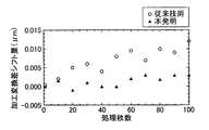
図3は、SF6系のプラズマクリーニングを実施後、ウェハ100枚の連続処理を行った場合の、加工変換差について、本発明の基板表面の処理方法に従って、バイアス電圧が所定範囲内に入っていて略一定となるよう、プラズマを生成するための電磁波供給源を制御した実施例1(図3に示すグラフ中、▲で示す)と、電磁波供給源を制御を行わずに、一定電力の供給を続けた比較例1(図3に示すグラフ中、○で示す)での、加工変換差シフト量の推移を示したものである。縦軸が加工変換差シフト量[μm]、横軸が処理枚数である。
【0057】
実施例1、比較例1において、ガス流量、チャンバ内圧力、バイアス電圧を印加するための高周波電源の電力および周波数は以下のとおりであった。
Cl2,HBr, O2流量:50sccm、50sccm、5sccm
チャンバ内圧力:0.5Pa
高周波電源の電力および周波数:30W、800KHz
バイアス電圧の所定範囲:±2.5%
【0058】
比較例1では、100枚の連続処理で、加工変換差シフト量が+0.01μm以上であったのに対し、実施例1では+0.005μm以下であった。
【0059】
(実施例2、比較例2)
サンプルとして、シリコン基板上に熱酸化により4nmのゲート酸化膜を形成し、その後、CVD法でundoped poly Siを200nm堆積したものにレジストパターンを形成したもの(製品サンプル)と、シリコン基板上に熱酸化により100nmの熱酸化膜を形成し、レジストパターンを形成したもの(選択比測定用サンプル)を用いた。
上記製品サンプルのエッチングを行うと共に、定期的に、上記サンプルを一般的なオーバーエッチング条件であるHBr−O2系プラズマでエッチングし、エッチング前後の膜厚差を光学式膜厚計で計測し、酸化膜に対するpoly Siの選択比(エッチング速度比)を算出した。
【0060】
図4は、製造ラインで使い古されたアース電極を交換した前後に、本発明の基板表面の処理方法に従って、バイアス電圧が所定範囲内に入っていて略一定となるよう、プラズマを生成するための電磁波供給源を制御した実施例2(図4に示すグラフ中、▲で示す)と、電磁波供給源を制御を行わずに、一定電力の供給を続けた比較例2(図4に示すグラフ中、○で示す)での、poly Si/SiO2エッチングレート比(poly Si/SiO2選択比)の変化について示したものである。縦軸がpoly Si/SiO2選択比、横軸が放電時間の累積値[hr]である。
【0061】
実施例2、比較例2において、ガス流量、チャンバ内圧力、バイアス電圧を印加するための高周波電源の周波数は以下のとおりであった。
HBr,O2流量:100sccm、5sccm
チャンバ内圧力:1.5Pa
高周波電源の周波数:800KHz
バイアス電圧の所定範囲:±2.5%
【0062】
比較例2では、アース電極交換により、アース能力が急激に回復し、バイアス電圧が増大し、イオンアシストでエッチングされるSiO2がより選択されたため、poly Si/SiO2選択比が20%以上低下したが、実施例2では、選択比はアース電極交換の影響をほとんど受けず、プロセス性能が安定に維持されたことが分かる。
【0063】
【発明の効果】
本発明によれば、バイアス電圧、あるいはさらに、プラズマからチャンバ内壁もしくはアース電極に流れるアース電流を監視することにより、プラズマの状態を把握することが出来、プラズマ密度や、入射イオンエネルギ等のプラズマの状態を一定範囲に保つように、プラズマを生成するために印加される第1の電磁波供給源の電力を制御することにより、被処理基板に入射するイオンエネルギを一定にすることができる。
【0064】
この結果、本発明によれば、チャンバクリーニングやパーツ交換、連続処理による反応生成物の付着の影響を受けることなく、常に一定のプロセスを維持することが出来る。すなわち、チャンバ内の環境の変化による、マイクロローディング効果、エッチングストップ、下地選択性の悪化、加工変換差のシフト等を抑止することが出来る。
【図面の簡単な説明】
【図1】 本発明の半導体製造装置の一実施例を模式的に表した断面図である。
【図2】 本発明の基板処理の方法の一実施例における、制御手段の動作を概略的に示したフローチャートである。
【図3】 基板表面の処理において、バイアス電圧を所定範囲内に保持する制御を行ってプラズマエッチングを行ったときと、バイアス電圧を制御せずにプラズマエッチングを行ったときの、エッチング前後の寸法差を示すグラフである。
【図4】 基板表面の処理において、バイアス電圧を所定範囲内に保持する制御を行ってプラズマエッチングを行ったときと、バイアス電圧を制御せずにプラズマエッチングを行ったときの、アース電極交換前後の下地選択比の変化を示すグラフである。
【図5】 ECR励起を利用した従来の半導体製造装置を模式的に示した断面図である。
【図6】 マイクロローディング効果によりSiNエッチングで開口不良が生じたウェハを表す模式図である。
【図7】 バイアス電圧変動によりSiNエッチング時に下地酸化膜抜けが生じたウェハを表す模式図である。
【符号の説明】
10 プラズマエッチング装置
20 プラズマ源
21 チャンバ
22 空洞共振部
23 石英天板
24 ガスシャワープレート
25 マイクロ波供給源
26 導波管
27a コイル
27b コイル
27c コイル
28 下部電極
29 高周波電源
30 測定部
30a アース電流を測定する第1の測定手段
30b バイアス電圧を測定する第2の測定手段
31 制御部
32 可変コンダクタンスバルブ
34 真空ポンプ[0001]
BACKGROUND OF THE INVENTION
The present invention relates to a semiconductor manufacturing apparatus, a method for processing a surface of a substrate to be processed, and a method for observing an adhesion state of a plasma product.
[0002]
[Prior art]
Conventionally, a plasma etching apparatus for microfabrication introduces a process gas suitable for a film to be etched into a chamber and generates plasma at a high frequency such as microwaves, 13.56 MHz, 27 MHz, 60 MHz, etc. By applying a bias voltage to the electrode on which the film is installed, anisotropic processing of the film to be etched has been realized while controlling the ion energy incident on the wafer from the plasma. As these typical discharge types, there are ECR (Electron Cyclotron Resonance) and ICP (Inductively Coupled Plasma), and high-density plasma can be obtained at low pressure.
[0003]
Hereinafter, a conventional plasma etching apparatus using ECR excitation will be described.
FIG. 5 is a cross-sectional view schematically showing the chamber structure of the
[0004]
A
[0005]
The
[0006]
When etching a substrate to be processed using the
[0007]
[Problems to be solved by the invention]
By the way, even in such a plasma etching apparatus, with the miniaturization of semiconductor processing, requirements for the etching process (for example, low microloading effect, high selectivity, high reproducibility, and high-precision processing) are becoming increasingly severe. . However, these requirements have complicated trade-off relationships, and the stable region that satisfies all of them is extremely narrow. And even now, even in this stable region, it is shifted over time due to accumulation of etching products.
[0008]
For example, in the oxide film etching performed by the
[0009]
First, in the hole processing in the
[0010]
Further, in nitride film etching and gate etching for element isolation (LOCOS formation), it is required to etch with high selectivity with respect to a thin oxide film or oxynitride film as a base. Again, if the earthing capability is reduced, the microloading effect is increased.
[0011]
FIG. 6 shows an example in which etching residue occurs due to the microloading effect in the nitride film etching. FIG. 6 is a photograph of the top, left, center, right, and bottom in the same plane of the wafer in order from the top. All show the same active pattern. The white part is the etched part. For example, in the center of the center, a large etched white part is seen, and both sides appear black. This black part is the part where the slits on both sides of the center that are clearly visible at the bottom are etched, but because the etching was not sufficient due to the microloading effect, the nitride film remained and it looked black Yes.
Thus, the decrease in Vpp decreases the ion energy incident on the wafer, and the decrease in the etch rate of narrow spaces is increased.
[0012]
Replacing the ground electrode during maintenance restores the earthing ability. However, if the earthing ability is restored more than before due to individual differences in the parts, etc., the plasma ion density in the chamber decreases and the set power is maintained. The Vpp of the lower electrode increases. As a result, the incident ion energy increases and the substrate selectivity deteriorates.
[0013]
FIG. 7 shows an example in which Vpp increases due to the replacement of the ground electrode and the base oxide film is lost in the nitride film etching. FIG. 7 is an image of the top, left, center, right, and bottom in the same plane of the wafer in order from the top. The top, left, center, right, and bottom are covered with resist at the center and appear black, but worm-like holes are visible on both sides. These are the portions where the pad oxide film was broken and the etching progressed to the silicon substrate.
[0014]
6 and 7 show the results of long-term fluctuations, but there are fluctuations between wafers and lots in a lot as short-term fluctuations.
One cause of a decrease in the yield of the semiconductor manufacturing apparatus is the fall of foreign matter caused by deposits in the chamber. In order to prevent this, periodic plasma cleaning is performed. However, the surface of the ground electrode immediately after the plasma cleaning is clean, but the grounding ability is reduced due to the influence of deposits and the like as the wafer processing progresses, so that no major troubles such as the above-described microloading effect and underlayer oxide film removal occur. Until now, the level of reproducibility of microfabrication (such as shifts in dimensions and substrate selectivity) will be affected.
[0015]
In response to the above-described problem of the prior art that the energy of ions incident on the wafer fluctuates during the process, the power of a radio frequency (RF) power source that supplies radio frequency (RF) power to the lower electrode has been controlled so far. A method of controlling the etching rate by setting Vpp to a predetermined value (Japanese Patent Laid-Open No. 8-199378) has been proposed. However, if the high-frequency power is controlled so that Vpp is constant, depending on the processing state, there is a problem that the high-frequency power is excessively supplied or insufficiently supplied, so that etching performance, particularly shape control cannot be performed.
[0016]
[Problems to be solved by the invention]
It is an object of the present invention to maintain a process at a constant etching rate at all times, and to provide a semiconductor manufacturing apparatus, a substrate surface to be processed, and a low microloading effect, high base selectivity, high reproducibility, and high precision processing. It is an object of the present invention to provide a processing method and a method for observing the state of adhesion of plasma products in a semiconductor manufacturing apparatus in order to enable these.
[0017]
[Means for Solving the Problems]
In general, problems in the prior art such as an increase in microloading effect, deterioration of substrate selectivity, and decrease in reproducibility of microfabrication, which occur as a result of fluctuations in ion density during the process and incident ion energy on the wafer, , The time course of the interaction of the plasma with the chamber wall or ground electrode.
[0018]
The present inventor can monitor this change over time by directly measuring the earth current flowing in the chamber wall or the earth electrode, and indirectly, on the lower electrode side on which the substrate to be processed is placed. It is found that the bias voltage can be monitored by measuring the applied bias voltage, and further, the aging of the interaction between the inner wall of the chamber or the earth electrode and the plasma is unavoidable, but the bias voltage is monitored, By controlling the power of the electromagnetic wave (plasma wave) supply source that supplies the microwave so that the value is maintained within a predetermined range, the charged particle (ion) density in the plasma in the chamber can be compensated. Thus, the inventors have found that the problems of the prior art can be solved and the above object can be achieved, and the present invention has been completed.
[0020]
That is, according to the present invention, charged particles in plasma are incident on the surface of the substrate to be processed with energy controlled by the bias voltage, and the surface of the substrate to be processed is processed.Plasma etching A device,
A plasma source for generating the plasma by applying a first electromagnetic wave supplied from a microwave supply source to a gas atmosphere in the chamber;
A bias source for generating the bias voltage by applying a second electromagnetic wave supplied from a high-frequency power source to cause charged particles in the plasma to enter the substrate to be processed;
First measuring means for measuring the bias voltage;
Second measuring means for measuring an earth current flowing from the plasma to the inner wall of the chamber or the earth electrode with which the plasma contacts;
Based on the bias voltage measured by the first measuring means and the measurement result of the ground current by the second measuring means, the power of the first electromagnetic wave from the microwave supply source and the high frequency power supply And control means for controlling the power of the second electromagnetic wave to maintain the bias voltage within the predetermined range.Plasma etching Providing equipment.
[0022]
In addition, the present invention applies a first electromagnetic wave supplied from a microwave supply source to a gas atmosphere in a chamber to generate plasma, and applies a second electromagnetic wave supplied from a high-frequency power source to apply a bias. A voltage is generated, and charged particles in the plasma are incident on the surface of the substrate to be processed with energy controlled by the bias voltage to process the surface of the substrate to be processed.Plasma etching A method,
Measuring the bias voltage at least during this process;
The earth current flowing from the plasma to the chamber inner wall or the earth electrode in contact with the plasma is measured, and the first electromagnetic wave from the microwave source is measured based on the measured bias voltage and the measurement result of the earth current. The bias voltage is maintained within the predetermined range by controlling either power or power of the second electromagnetic wave from the high-frequency power source.Plasma etching Provide a method.
[0023]
When the bias voltage cannot be maintained within the predetermined range by controlling the power of the first electromagnetic wave, the bias voltage is further maintained within the predetermined range by controlling the power of the second electromagnetic wave. It is preferable to do this.
[0024]
In addition, the present invention applies a first electromagnetic wave supplied from a microwave supply source to a gas atmosphere in a chamber to generate plasma, and applies a second electromagnetic wave supplied from a high-frequency power source to apply a bias. A voltage is generated, and charged particles in the plasma are incident on the surface of the substrate to be processed with energy controlled by the bias voltage to process the surface of the substrate to be processed.Plasma etching A method,
At least one time of this process, the bias voltage is measured, and an earth current flowing from the plasma to the inner wall of the chamber or the earth electrode in contact with the plasma is measured, and the measured bias voltage deviates from a first predetermined range. And when the measured ground current deviates from the second predetermined range, the power of the first electromagnetic wave is controlled to keep the bias voltage within the first predetermined range. It is characterized byPlasma etching Provide a method.
[0025]
Furthermore, the present invention is a method for observing the adhesion state of a plasma product in a chamber, wherein an electromagnetic wave is applied to a gas atmosphere in the chamber to generate plasma, and the plasma is in contact with the plasma from the plasma Provided is a method for observing the state of adhesion of plasma products to the inner wall of the chamber or the ground electrode by measuring the ground current flowing through the inner wall or the ground electrode.
[0026]
DETAILED DESCRIPTION OF THE INVENTION
A semiconductor manufacturing apparatus, a processing method for a surface of a substrate to be processed, and a method for observing an adhesion state of a plasma product according to the present invention will be described below in detail based on preferred embodiments shown in the accompanying drawings.
FIG. 1 shows an ECR plasma etching apparatus according to an embodiment of the semiconductor manufacturing apparatus of the present invention for carrying out the processing method of the substrate surface of the present invention and the method of observing the adhesion state of the plasma product. Needless to say, the present invention is not limited to the illustrated examples.
The
[0027]
The
[0028]
One end of current measuring means 30a for measuring the earth current is connected to the
One end of a
[0029]
The
With respect to the ground current and the bias voltage, an allowable predetermined range including a reference ground current value as a central value and an allowable predetermined range including a reference bias voltage value as a central value are set in advance. An input signal corresponding to the bias voltage measured by the
That is, when the measured bias voltage exceeds the upper limit of the predetermined range, the power of the
As a result, the
[0030]
In the
[0031]
For example, even if the bias voltage measured by the
Whether or not it is appropriate to control the high-frequency power in this way is determined by whether or not the ground current measured by the current measuring means 30a is within a predetermined range, for example.
[0032]
In the
[0033]
The semiconductor manufacturing apparatus of the present invention is basically configured as described above, but referring to the configuration of the semiconductor manufacturing apparatus described below, the processing method of the surface of the substrate to be processed of the present invention and the adhesion state of plasma products A method for observing the above will be described in detail.
[0034]
In the processing method of the surface of the substrate to be processed according to the present invention, at least one time of the processing, the bias voltage is measured, and the power of the
[0035]
Regarding the bias voltage, an allowable predetermined range including a reference bias voltage value is set in advance. In the predetermined range, a lower limit and an upper limit allowed as a target are set around a target reference bias voltage value. Specifically, for example, a range of ± 2.5% around the reference bias voltage value is preferably set as the predetermined range. The predetermined range is stored in the
[0036]
The predetermined range is preferably set for each step of etching.
Although it is conceivable that the bias voltage differs even at the same ion density due to the change in the etching layer of the substrate to be processed, even in such a case, it may coincide with a predetermined range of a preferable bias voltage in each etching step. is important.
[0037]
When an input signal corresponding to the bias voltage measured by the
The signal input to the
On the other hand, when the measured bias voltage falls below the lower limit of the predetermined range, a signal instructing a decrease in the power of the microwave is input from the
[0038]
Thus, by measuring the bias voltage by the
[0039]
It is considered that the fluctuation of the plasma ion density in the
[0040]
However, there may be a case where the bias voltage fluctuates due to a cause other than the earth ability. In such a case, it is preferable to control the power of the high
When the bias voltage cannot be maintained within a predetermined range only by the power control of the
[0041]
In addition, when a change in bias voltage is detected, the earth current is measured and compared with a predetermined range to determine whether the change in bias voltage is caused by a change in grounding capacity, etc. And based on the determination result, it is also possible to determine whether the microwave power should be controlled or the high frequency power should be controlled. That is, when the measured value of the ground current deviates from the predetermined range, especially when the direction of the deviation is a direction that can be interpreted as being caused by the earth capacity fluctuation, the fluctuation of the bias voltage is the earth capacity or the like. Therefore, the microwave power is controlled. On the other hand, if the ground current is within the specified range, or if the ground current deviates from the specified range in the direction opposite to the direction of fluctuation that can be interpreted as being caused by the earth capacity fluctuation, The high frequency power is adjusted by judging that the fluctuation does not occur.
[0042]
In such a case, an allowable predetermined range including a reference ground current value is set in advance for the ground current. In the predetermined range, a lower limit and an upper limit allowed as a target are set around the target reference ground current value. Specifically, for example, a range of ± 8% around the reference ground current value is preferably set as the predetermined range. The predetermined range is preferably set for each step of etching. The predetermined range is stored in the
[0043]
In addition, when processing by the processing method of the substrate surface of the present invention is continuously performed, by changing the microwave power to a value different from the initial set value by controlling the microwave power, the processing is continued. There is. When a change in the bias voltage is detected again after this change, in order to determine whether or not the fluctuation is caused by a change in grounding capacity or the like, the predetermined range of the ground current depends on the microwave power. It is preferable to set the format. Alternatively, when the microwave power is changed, the earth current immediately after that is measured and stored in the
[0044]
When deposits begin to accumulate on the inner wall of the
[0045]
In the processing method for the surface of the substrate to be processed according to the present invention, the bias voltage is measured at least at one time of the processing of the surface of the substrate to be processed. The measurement may be performed once or twice or more during the treatment period, or may be performed continuously, repeatedly, or continuously over the entire treatment period. By constantly measuring the bias voltage during the period during which the actual surface of the substrate to be processed is being processed and controlling the microwave power so as to be held within a predetermined range, the bias voltage is adjusted for each wafer. It is possible to prevent the occurrence of a period outside the predetermined range, maintain a constant etching rate, obtain higher dimensional stability, higher reproducibility, and higher selectivity, and reduce the microloading effect. it can.
[0046]
In this way, a particularly remarkable effect can be obtained by measuring the bias voltage in real time and controlling the microwave power during the period during which the surface of the substrate to be processed is actually processed. However, when a large change in the environment in the chamber is expected, such as when replacing the ground electrode, first, a bias voltage is measured and microwave power is controlled using a dummy wafer to generate a bias voltage within a predetermined range. It is preferable to start the actual processing of the surface of the substrate to be processed after adjusting the apparatus to the state to be performed. In this case, the measurement of the bias voltage and the control of the microwave power are performed at a time during the entire process including the preparation of the apparatus, although it is not during the period of actually processing the surface of the substrate to be processed. Is called. Needless to say, it is more preferable to use both measurement and control in the preparation stage and real-time measurement and control during the processing of the actual surface of the substrate to be processed.
[0047]
Next, in one embodiment of the processing method of the substrate surface of the present invention, the bias voltage is controlled within the predetermined range by controlling the power of the first electromagnetic wave or further the power of the second electromagnetic wave. Will be described based on the flowchart shown in FIG.
[0048]
When the control is started, it is determined in S1 whether the measured bias voltage is equal to or lower than the upper limit of a predetermined range of the bias voltage set in advance prior to etching. If it is determined that it is not less than the upper limit, it is determined in S2 whether the earth current is less than or equal to an upper limit of a predetermined range of the earth current set in advance prior to etching. If it is determined that the value is not less than the upper limit, it is determined in S3 whether the output of the magnetron that generates the electromagnetic wave of the first electromagnetic wave supply source (that is, the power of the first electromagnetic wave supply source) is within an allowable range. If it is determined that it is not within the allowable range, it is determined that the plasma etching process is abnormal, and an alarm is issued. This alarm can prevent abnormal plasma processing. If it is determined that the value is within the allowable range, a signal instructing to increase the output of the magnetron is output from the control means to the magnetron, and thereafter, the process returns to S1.
[0049]
If it is determined in S2 that the earth current is equal to or lower than the upper limit of a predetermined range of the earth current set in advance prior to etching, in S4, the output of the high frequency power supply (RF) that is the second electromagnetic wave supply source (that is, , The power of the second electromagnetic wave supply source) is within an allowable range. If it is determined that it is not within the allowable range, an alarm is issued. If it is determined that it is within the allowable range, a signal for instructing to reduce the output of the RF is output to the RF from the aforementioned control means, and thereafter, the process returns to S1.
[0050]
On the other hand, if it is determined in S1 that the measured bias voltage is not more than the upper limit of the predetermined range of the bias voltage set in advance prior to etching, whether or not the bias voltage is not less than the lower limit of the predetermined range in S5. If it is determined that it is not equal to or lower than the lower limit, it is determined in S6 whether the ground current is equal to or higher than the lower limit. If it is determined that it is not equal to or lower than the lower limit, it is determined in S7 whether the number of processed substrates is N or less after the plasma cleaning performed before the etching process is started. If it is determined that the number is not less than N, that is, if N is a considerable number, it is considered that the deposition of plasma products adhering to the chamber wall is progressing, and thus plasma cleaning is performed. N may be selected from, for example, the value of the number of wafers included in one lot, and it may be determined whether plasma cleaning is necessary in one lot, or the number of wafers in two cassettes in which two lots are combined The value may be selected from the value of the number of sheets and determined within the range of two cassettes, or a value set arbitrarily.
[0051]
However, if it is determined that the number is N or less, since the number of processed sheets is small after the etching process is started, the deposition of plasma products is not the cause. It is determined whether it is within the allowable range. If it is determined that it is not within the allowable range, it is determined that the plasma etching process is abnormal, and an alarm is issued. If it is determined that the value is within the allowable range, a signal instructing to lower the output of the magnetron is output from the control means to the magnetron, and thereafter, the process returns to S1.
[0052]
In S6, it is determined that the ground current is equal to or higher than the lower limit, and in S8, it is determined whether the output of the high frequency power source as the second electromagnetic wave supply source is within an allowable range. If it is determined that it is not within the allowable range, an alarm is issued. If it is determined that it is within the allowable range, a signal instructing to increase the output of the RF is output to the RF from the aforementioned control means, and thereafter, the process returns to S1.
[0053]
If it is determined in S5 that the bias voltage is equal to or higher than the lower limit of the predetermined range, the etching process is continued.
[0054]
【Example】
Hereinafter, examples of the present invention will be shown to describe the present invention more specifically. Here, a case where the
[0055]
(Example 1, Comparative Example 1)
As a sample, a gate oxide film having a thickness of 4 nm was formed on a silicon substrate by thermal oxidation, and then a 200 nm thick layer of undoped poly Si was deposited by CVD, and a resist pattern having a line width of about 0.15 μm was used. .
The above sample is Cl2 -HBr-O2 Etching was performed with system plasma, and the dimensional difference before and after etching was measured with a length measuring SEM.
[0056]
Figure 3 shows SF6 Regarding the processing conversion difference when 100 wafers are continuously processed after the system plasma cleaning is performed, the bias voltage is within a predetermined range and becomes substantially constant according to the substrate surface processing method of the present invention. Example 1 (indicated by ▲ in the graph shown in FIG. 3) in which the electromagnetic wave supply source for generating plasma was controlled, and Comparative Example 1 in which the supply of constant power was continued without controlling the electromagnetic wave supply source The transition of the machining conversion difference shift amount at (shown by ◯ in the graph shown in FIG. 3) is shown. The vertical axis represents the processing conversion difference shift amount [μm], and the horizontal axis represents the number of processed sheets.
[0057]
In Example 1 and Comparative Example 1, the power and frequency of the high-frequency power source for applying the gas flow rate, the pressure in the chamber, and the bias voltage were as follows.
Cl2 , HBr, O2 Flow rate: 50sccm, 50sccm, 5sccm
Chamber pressure: 0.5Pa
Power and frequency of high frequency power supply: 30W, 800KHz
Bias voltage range: ± 2.5%
[0058]
In Comparative Example 1, the processing conversion difference shift amount was +0.01 μm or more in the continuous processing of 100 sheets, whereas in Example 1, it was +0.005 μm or less.
[0059]
(Example 2, comparative example 2)
As a sample, a gate oxide film of 4 nm is formed on a silicon substrate by thermal oxidation, and then a resist pattern is formed on a silicon film deposited with 200 nm of undoped poly Si by CVD (product sample), and heat is applied on the silicon substrate. A 100 nm thermal oxide film was formed by oxidation and a resist pattern was formed (selection ratio measurement sample).
The product sample is etched, and periodically, the sample is subjected to HBr-O, which is a general over-etching condition.2 Etching was performed with system plasma, and the difference in film thickness before and after etching was measured with an optical film thickness meter to calculate the poly Si selection ratio (etching rate ratio) to the oxide film.
[0060]
FIG. 4 is a diagram for generating plasma so that the bias voltage is within a predetermined range and becomes substantially constant according to the substrate surface processing method of the present invention before and after replacing a ground electrode that has been used in the production line. Example 2 (indicated by ▲ in the graph shown in FIG. 4) in which the electromagnetic wave supply source was controlled, and Comparative Example 2 (in the graph shown in FIG. 4) in which the supply of constant power was continued without controlling the electromagnetic wave supply source. Poly Si / SiO2 Etching rate ratio (poly Si / SiO2 This shows the change in the selection ratio. The vertical axis is poly Si / SiO2 The selection ratio, the horizontal axis is the cumulative value [hr] of the discharge time.
[0061]
In Example 2 and Comparative Example 2, the frequency of the high-frequency power source for applying the gas flow rate, the pressure in the chamber, and the bias voltage was as follows.
HBr, O2 Flow rate: 100sccm, 5sccm
Chamber pressure: 1.5Pa
Frequency of high frequency power supply: 800KHz
Bias voltage range: ± 2.5%
[0062]
In Comparative Example 2, by replacing the earth electrode, the earth ability is rapidly recovered, the bias voltage is increased, and SiO etched by ion assist is used.2 Was more selected, so poly Si / SiO2 Although the selection ratio decreased by 20% or more, it can be seen that in Example 2, the selection ratio was hardly affected by the replacement of the ground electrode, and the process performance was maintained stably.
[0063]
【The invention's effect】
According to the present invention, the state of the plasma can be grasped by monitoring the bias voltage or the earth current flowing from the plasma to the inner wall of the chamber or the earth electrode, and the plasma density, incident ion energy, etc. By controlling the power of the first electromagnetic wave supply source applied to generate plasma so as to keep the state in a certain range, the ion energy incident on the substrate to be processed can be made constant.
[0064]
As a result, according to the present invention, a constant process can always be maintained without being affected by the adhesion of reaction products due to chamber cleaning, parts replacement, and continuous processing. That is, it is possible to suppress the microloading effect, the etching stop, the deterioration of the substrate selectivity, the shift of the processing conversion difference, and the like due to the environmental change in the chamber.
[Brief description of the drawings]
FIG. 1 is a cross-sectional view schematically showing an embodiment of a semiconductor manufacturing apparatus of the present invention.
FIG. 2 is a flowchart schematically showing the operation of the control means in one embodiment of the substrate processing method of the present invention.
FIG. 3 shows dimensions before and after etching when plasma etching is performed by controlling the bias voltage to be maintained within a predetermined range and when plasma etching is performed without controlling the bias voltage. It is a graph which shows a difference.
FIG. 4 shows a process for controlling the surface of the substrate to maintain the bias voltage within a predetermined range and perform plasma etching before and after the replacement of the ground electrode when performing plasma etching without controlling the bias voltage. It is a graph which shows the change of the base | substrate selection ratio.
FIG. 5 is a cross-sectional view schematically showing a conventional semiconductor manufacturing apparatus using ECR excitation.
FIG. 6 is a schematic view showing a wafer in which an opening defect is caused by SiN etching due to a microloading effect.
FIG. 7 is a schematic diagram showing a wafer in which a base oxide film is missing during SiN etching due to bias voltage fluctuations.
[Explanation of symbols]
10 Plasma etching equipment
20 Plasma source
21 chambers
22 Cavity resonance part
23 Quartz top plate
24 gas shower plate
25 Microwave source
26 Waveguide
27a coil
27b coil
27c coil
28 Lower electrode
29 High frequency power supply
30 Measuring unit
30a First measuring means for measuring earth current
30b Second measuring means for measuring bias voltage
31 Control unit
32 Variable conductance valve
34 Vacuum pump
Claims (4)
Translated fromJapaneseチャンバ内のガス雰囲気に、マイクロ波供給源から供給される第1の電磁波を印加して前記プラズマを生成するプラズマ源と、
前記被処理基板に前記プラズマ中の荷電粒子を入射させるために高周波電源から供給される第2の電磁波を印加して前記バイアス電圧を発生させるバイアス源と、
前記バイアス電圧を測定する第1の測定手段と、
前記プラズマからこのプラズマが接する前記チャンバ内壁もしくはアース電極に流れるアース電流を測定する第2の測定手段と、
前記第1の測定手段によって測定された前記バイアス電圧と前記第2の測定手段による前記アース電流の測定結果に基づいて、前記マイクロ波供給源からの第1の電磁波の電力と前記高周波電源からの第2の電磁波の電力とのいずれかを制御することによって、前記バイアス電圧を前記所定範囲内に保持する制御手段とを有することを特徴とするプラズマエッチング装置。Aplasma etching apparatus for processing charged substrate surfaces by causing charged particles in the plasma to be incident on the substrate surface to be processed with energy controlled by a bias voltage,
A plasma source for generating the plasma by applying a first electromagnetic wave supplied from a microwave supply source to a gas atmosphere in the chamber;
A bias source for generating the bias voltage by applying a second electromagnetic wave supplied from a high-frequency power source to cause charged particles in the plasma to enter the substrate to be processed;
First measuring means for measuring the bias voltage;
Second measuring means for measuring an earth current flowing from the plasma to the inner wall of the chamber or the earth electrode with which the plasma contacts;
Based on the bias voltage measured by the first measuring means and the measurement result of the ground current by the second measuring means, the power of the first electromagnetic wave from the microwave supply source and the high frequency power supply Aplasma etching apparatus comprising: control means for maintaining the bias voltage within the predetermined range by controlling any one of the power of the second electromagnetic wave.
この処理の少なくとも一時期に、前記バイアス電圧を測定すると共に、
前記プラズマからこのプラズマが接する前記チャンバ内壁もしくはアース電極に流れるアース電流を測定し、測定された前記バイアス電圧と該アース電流の測定結果に基づいて、前記マイクロ波供給源からの第1の電磁波の電力と前記高周波電源からの第2の電磁波の電力とのいずれかを制御して、前記バイアス電圧を前記所定範囲内に保持することを特徴とするプラズマエッチング方法。A plasma is generated by applying a first electromagnetic wave supplied from a microwave supply source to the gas atmosphere in the chamber, and a bias voltage is generated by applying a second electromagnetic wave supplied from a high-frequency power source, Aplasma etching method in which charged particles in the plasma are incident on a surface of a processing substrate with energy controlled by the bias voltage, and the surface of the processing substrate is processed.
Measuring the bias voltage at least during this process;
The earth current flowing from the plasma to the chamber inner wall or the earth electrode in contact with the plasma is measured, and the first electromagnetic wave from the microwave source is measured based on the measured bias voltage and the measurement result of the earth current. Aplasma etching method, wherein either the electric power or the electric power of the second electromagnetic wave from the high frequency power source is controlled to maintain the bias voltage within the predetermined range.
この処理の少なくとも一時期に、前記バイアス電圧を測定すると共に、前記プラズマからこのプラズマが接する前記チャンバ内壁もしくはアース電極に流れるアース電流を測定し、測定された前記バイアス電圧が第1の所定範囲から逸脱し、かつ、測定された前記アース電流が第2の所定範囲から逸脱している場合に、前記第1の電磁波の電力を制御して、前記バイアス電圧を前記第1の所定範囲内に保持することを特徴とするプラズマエッチング方法。A plasma is generated by applying a first electromagnetic wave supplied from a microwave supply source to the gas atmosphere in the chamber, and a bias voltage is generated by applying a second electromagnetic wave supplied from a high-frequency power source, Aplasma etching method in which charged particles in the plasma are incident on a surface of a processing substrate with energy controlled by the bias voltage, and the surface of the processing substrate is processed.
At least one time of this process, the bias voltage is measured, and an earth current flowing from the plasma to the inner wall of the chamber or the earth electrode in contact with the plasma is measured, and the measured bias voltage deviates from a first predetermined range. And when the measured ground current deviates from the second predetermined range, the power of the first electromagnetic wave is controlled to keep the bias voltage within the first predetermined range. Aplasma etching method.
Priority Applications (2)
| Application Number | Priority Date | Filing Date | Title |
|---|---|---|---|
| JP2000307237AJP4666740B2 (en) | 2000-10-06 | 2000-10-06 | Semiconductor manufacturing apparatus, substrate surface processing method, and plasma product adhesion state observation method |
| US09/970,763US6815369B2 (en) | 2000-10-06 | 2001-10-05 | Method for monitoring deposition reaction during processing the surface of a semiconductor substrate |
Applications Claiming Priority (1)
| Application Number | Priority Date | Filing Date | Title |
|---|---|---|---|
| JP2000307237AJP4666740B2 (en) | 2000-10-06 | 2000-10-06 | Semiconductor manufacturing apparatus, substrate surface processing method, and plasma product adhesion state observation method |
Publications (3)
| Publication Number | Publication Date |
|---|---|
| JP2002118095A JP2002118095A (en) | 2002-04-19 |
| JP2002118095A5 JP2002118095A5 (en) | 2007-12-06 |
| JP4666740B2true JP4666740B2 (en) | 2011-04-06 |
Family
ID=18787782
Family Applications (1)
| Application Number | Title | Priority Date | Filing Date |
|---|---|---|---|
| JP2000307237AExpired - Fee RelatedJP4666740B2 (en) | 2000-10-06 | 2000-10-06 | Semiconductor manufacturing apparatus, substrate surface processing method, and plasma product adhesion state observation method |
Country Status (2)
| Country | Link |
|---|---|
| US (1) | US6815369B2 (en) |
| JP (1) | JP4666740B2 (en) |
Families Citing this family (11)
| Publication number | Priority date | Publication date | Assignee | Title |
|---|---|---|---|---|
| KR100476460B1 (en)* | 2001-11-05 | 2005-03-17 | 주성엔지니어링(주) | Plasma prcess chamber monitoring method and system used therefor |
| DE112005001429T5 (en)* | 2004-06-18 | 2007-04-26 | Innovalight, Inc., St. Paul | Method and apparatus for forming nanoparticles using radio frequency plasmas |
| JP4722669B2 (en)* | 2005-10-26 | 2011-07-13 | 株式会社日立ハイテクインスツルメンツ | Plasma cleaning device |
| US8004293B2 (en)* | 2006-11-20 | 2011-08-23 | Applied Materials, Inc. | Plasma processing chamber with ground member integrity indicator and method for using the same |
| US20090014423A1 (en)* | 2007-07-10 | 2009-01-15 | Xuegeng Li | Concentric flow-through plasma reactor and methods therefor |
| WO2008091581A1 (en) | 2007-01-22 | 2008-07-31 | The University Of Minnesota | Nanoparticles with grafted organic molecules |
| WO2008143716A2 (en)* | 2007-01-22 | 2008-11-27 | Innovalight, Inc. | In situ modification of group iv nanoparticles using gas phase nanoparticle reactors |
| US8471170B2 (en) | 2007-07-10 | 2013-06-25 | Innovalight, Inc. | Methods and apparatus for the production of group IV nanoparticles in a flow-through plasma reactor |
| US8968438B2 (en)* | 2007-07-10 | 2015-03-03 | Innovalight, Inc. | Methods and apparatus for the in situ collection of nucleated particles |
| JP4777481B2 (en)* | 2008-08-11 | 2011-09-21 | 住友精密工業株式会社 | Plasma control device |
| US10962483B2 (en)* | 2017-10-03 | 2021-03-30 | Innotech Alberta Inc. | Reduction of molecular background emission and sample matrix management in a solution cathode glow discharge |
Family Cites Families (26)
| Publication number | Priority date | Publication date | Assignee | Title |
|---|---|---|---|---|
| KR0170387B1 (en)* | 1989-10-03 | 1999-03-30 | 제임스 조셉 드롱 | High-frequency semiconductor wafer processing method using a negative self-bias |
| JP3084944B2 (en) | 1992-07-30 | 2000-09-04 | 株式会社日立製作所 | Plasma generation method |
| JPH0684800A (en)* | 1992-09-04 | 1994-03-25 | Hitachi Ltd | Plasma process equipment |
| US5525159A (en)* | 1993-12-17 | 1996-06-11 | Tokyo Electron Limited | Plasma process apparatus |
| JPH07302696A (en)* | 1994-05-06 | 1995-11-14 | Hitachi Ltd | Earth line monitoring method and plasma processing apparatus using the same |
| US5576629A (en) | 1994-10-24 | 1996-11-19 | Fourth State Technology, Inc. | Plasma monitoring and control method and system |
| JP3116762B2 (en)* | 1995-01-27 | 2000-12-11 | 住友金属工業株式会社 | Plasma etching equipment |
| JP3292270B2 (en)* | 1995-02-27 | 2002-06-17 | 富士通株式会社 | Electrostatic suction device |
| US6283130B1 (en)* | 1995-05-30 | 2001-09-04 | Anelva Corporation | Plasma cleaning method and placement area protector used in the method |
| JPH0927395A (en)* | 1995-07-12 | 1997-01-28 | Kobe Steel Ltd | Plasma treatment device, and plasma treatment method using this device |
| JPH09232289A (en)* | 1996-02-28 | 1997-09-05 | Nec Kyushu Ltd | Dry etching apparatus |
| US6197116B1 (en) | 1996-08-29 | 2001-03-06 | Fujitsu Limited | Plasma processing system |
| JPH10101829A (en)* | 1996-10-01 | 1998-04-21 | Matsushita Electric Ind Co Ltd | Plastic substrate and method for manufacturing the same, and ink jet printer head and method for manufacturing the same |
| JP3402972B2 (en)* | 1996-11-14 | 2003-05-06 | 東京エレクトロン株式会社 | Method for manufacturing semiconductor device |
| JPH10240356A (en)* | 1997-02-21 | 1998-09-11 | Anelva Corp | Substrate temperature control method and substrate temperature controllability judgment method for substrate processing equipment |
| US6066399A (en)* | 1997-03-19 | 2000-05-23 | Sanyo Electric Co., Ltd. | Hard carbon thin film and method of forming the same |
| US6174450B1 (en)* | 1997-04-16 | 2001-01-16 | Lam Research Corporation | Methods and apparatus for controlling ion energy and plasma density in a plasma processing system |
| JPH11162958A (en)* | 1997-09-16 | 1999-06-18 | Tokyo Electron Ltd | Plasma processing apparatus and method |
| JP3726477B2 (en) | 1998-03-16 | 2005-12-14 | 株式会社日立製作所 | Plasma processing apparatus and plasma processing method |
| JP2000031072A (en) | 1998-07-10 | 2000-01-28 | Seiko Epson Corp | Plasma monitoring method and semiconductor manufacturing apparatus |
| EP1001459B1 (en)* | 1998-09-09 | 2011-11-09 | Texas Instruments Incorporated | Integrated circuit comprising a capacitor and method |
| JP3958877B2 (en)* | 1998-09-14 | 2007-08-15 | 大日本印刷株式会社 | Vacuum deposition system |
| JP2000208495A (en)* | 1999-01-18 | 2000-07-28 | Mitsubishi Electric Corp | Plasma processing method and plasma processing apparatus |
| JP2000299198A (en) | 1999-02-10 | 2000-10-24 | Tokyo Electron Ltd | Plasma processing device |
| JP3959200B2 (en) | 1999-03-19 | 2007-08-15 | 株式会社東芝 | Semiconductor device manufacturing equipment |
| US6563076B1 (en)* | 1999-09-30 | 2003-05-13 | Lam Research Corporation | Voltage control sensor and control interface for radio frequency power regulation in a plasma reactor |
- 2000
- 2000-10-06JPJP2000307237Apatent/JP4666740B2/ennot_activeExpired - Fee Related
- 2001
- 2001-10-05USUS09/970,763patent/US6815369B2/ennot_activeExpired - Fee Related
Also Published As
| Publication number | Publication date |
|---|---|
| US20020040765A1 (en) | 2002-04-11 |
| JP2002118095A (en) | 2002-04-19 |
| US6815369B2 (en) | 2004-11-09 |
Similar Documents
| Publication | Publication Date | Title |
|---|---|---|
| KR100405578B1 (en) | Method for manufacturing a semiconductor device | |
| KR970000417B1 (en) | Dry etching method and dry etching device | |
| JP3568749B2 (en) | Dry etching method for semiconductor | |
| JP6630649B2 (en) | Plasma processing method | |
| US5404079A (en) | Plasma generating apparatus | |
| KR100554426B1 (en) | How to adjust electrode thickness in plasma processing system | |
| JP4373338B2 (en) | Method and apparatus for determining the lifetime of consumables | |
| JP4801045B2 (en) | Method for removing chamber residue from a plasma processing system in a dry cleaning process | |
| JP5377993B2 (en) | Plasma processing method | |
| GB2381375A (en) | Plasma processing apparatus | |
| JP4666740B2 (en) | Semiconductor manufacturing apparatus, substrate surface processing method, and plasma product adhesion state observation method | |
| JP2016225376A (en) | Plasma processing apparatus and plasma processing method | |
| JP2011192872A (en) | Plasma treatment apparatus and plasma treatment method | |
| TW494485B (en) | Apparatus and method for plasma treatment | |
| JP2000294540A (en) | Manufacture of semiconductor device and apparatus for manufacturing | |
| JP2014053644A (en) | Plasma processing device and plasma processing method | |
| JP2013222910A (en) | Plasma processing method and plasma processing device | |
| JP6169666B2 (en) | Plasma processing method | |
| JP5853087B2 (en) | Plasma processing method | |
| TW202133264A (en) | Plasma processing method | |
| WO1999011103A1 (en) | Method for controlling plasma processor | |
| JP6851510B2 (en) | Plasma processing equipment and plasma processing method | |
| JPH10242130A (en) | Plasma processing method and apparatus | |
| JPH1064886A (en) | Device and method for dry etching | |
| US20050269293A1 (en) | Seasoning method for etch chamber |
Legal Events
| Date | Code | Title | Description |
|---|---|---|---|
| A521 | Request for written amendment filed | Free format text:JAPANESE INTERMEDIATE CODE: A523 Effective date:20071003 | |
| A621 | Written request for application examination | Free format text:JAPANESE INTERMEDIATE CODE: A621 Effective date:20071003 | |
| A977 | Report on retrieval | Free format text:JAPANESE INTERMEDIATE CODE: A971007 Effective date:20080331 | |
| A131 | Notification of reasons for refusal | Free format text:JAPANESE INTERMEDIATE CODE: A131 Effective date:20100727 | |
| A521 | Request for written amendment filed | Free format text:JAPANESE INTERMEDIATE CODE: A523 Effective date:20100917 | |
| A131 | Notification of reasons for refusal | Free format text:JAPANESE INTERMEDIATE CODE: A131 Effective date:20101019 | |
| A521 | Request for written amendment filed | Free format text:JAPANESE INTERMEDIATE CODE: A523 Effective date:20101208 | |
| TRDD | Decision of grant or rejection written | ||
| A01 | Written decision to grant a patent or to grant a registration (utility model) | Free format text:JAPANESE INTERMEDIATE CODE: A01 Effective date:20110104 | |
| A01 | Written decision to grant a patent or to grant a registration (utility model) | Free format text:JAPANESE INTERMEDIATE CODE: A01 | |
| A61 | First payment of annual fees (during grant procedure) | Free format text:JAPANESE INTERMEDIATE CODE: A61 Effective date:20110111 | |
| FPAY | Renewal fee payment (event date is renewal date of database) | Free format text:PAYMENT UNTIL: 20140121 Year of fee payment:3 | |
| R150 | Certificate of patent or registration of utility model | Ref document number:4666740 Country of ref document:JP Free format text:JAPANESE INTERMEDIATE CODE: R150 Free format text:JAPANESE INTERMEDIATE CODE: R150 | |
| S111 | Request for change of ownership or part of ownership | Free format text:JAPANESE INTERMEDIATE CODE: R313111 | |
| R350 | Written notification of registration of transfer | Free format text:JAPANESE INTERMEDIATE CODE: R350 | |
| R250 | Receipt of annual fees | Free format text:JAPANESE INTERMEDIATE CODE: R250 | |
| R250 | Receipt of annual fees | Free format text:JAPANESE INTERMEDIATE CODE: R250 | |
| R250 | Receipt of annual fees | Free format text:JAPANESE INTERMEDIATE CODE: R250 | |
| R250 | Receipt of annual fees | Free format text:JAPANESE INTERMEDIATE CODE: R250 | |
| R250 | Receipt of annual fees | Free format text:JAPANESE INTERMEDIATE CODE: R250 | |
| R250 | Receipt of annual fees | Free format text:JAPANESE INTERMEDIATE CODE: R250 | |
| LAPS | Cancellation because of no payment of annual fees |