JP4666215B2 - Article conveying device - Google Patents
Article conveying deviceDownload PDFInfo
- Publication number
- JP4666215B2 JP4666215B2JP2005232283AJP2005232283AJP4666215B2JP 4666215 B2JP4666215 B2JP 4666215B2JP 2005232283 AJP2005232283 AJP 2005232283AJP 2005232283 AJP2005232283 AJP 2005232283AJP 4666215 B2JP4666215 B2JP 4666215B2
- Authority
- JP
- Japan
- Prior art keywords
- article
- placement
- delivery
- placing
- location
- Prior art date
- Legal status (The legal status is an assumption and is not a legal conclusion. Google has not performed a legal analysis and makes no representation as to the accuracy of the status listed.)
- Expired - Fee Related
Links
Images


Classifications
- H—ELECTRICITY
- H01—ELECTRIC ELEMENTS
- H01L—SEMICONDUCTOR DEVICES NOT COVERED BY CLASS H10
- H01L21/00—Processes or apparatus adapted for the manufacture or treatment of semiconductor or solid state devices or of parts thereof
- H01L21/67—Apparatus specially adapted for handling semiconductor or electric solid state devices during manufacture or treatment thereof; Apparatus specially adapted for handling wafers during manufacture or treatment of semiconductor or electric solid state devices or components ; Apparatus not specifically provided for elsewhere
- H01L21/677—Apparatus specially adapted for handling semiconductor or electric solid state devices during manufacture or treatment thereof; Apparatus specially adapted for handling wafers during manufacture or treatment of semiconductor or electric solid state devices or components ; Apparatus not specifically provided for elsewhere for conveying, e.g. between different workstations
- H01L21/67703—Apparatus specially adapted for handling semiconductor or electric solid state devices during manufacture or treatment thereof; Apparatus specially adapted for handling wafers during manufacture or treatment of semiconductor or electric solid state devices or components ; Apparatus not specifically provided for elsewhere for conveying, e.g. between different workstations between different workstations
- H01L21/67715—Changing the direction of the conveying path
- H—ELECTRICITY
- H01—ELECTRIC ELEMENTS
- H01L—SEMICONDUCTOR DEVICES NOT COVERED BY CLASS H10
- H01L21/00—Processes or apparatus adapted for the manufacture or treatment of semiconductor or solid state devices or of parts thereof
- H01L21/67—Apparatus specially adapted for handling semiconductor or electric solid state devices during manufacture or treatment thereof; Apparatus specially adapted for handling wafers during manufacture or treatment of semiconductor or electric solid state devices or components ; Apparatus not specifically provided for elsewhere
- H01L21/677—Apparatus specially adapted for handling semiconductor or electric solid state devices during manufacture or treatment thereof; Apparatus specially adapted for handling wafers during manufacture or treatment of semiconductor or electric solid state devices or components ; Apparatus not specifically provided for elsewhere for conveying, e.g. between different workstations
- H01L21/67703—Apparatus specially adapted for handling semiconductor or electric solid state devices during manufacture or treatment thereof; Apparatus specially adapted for handling wafers during manufacture or treatment of semiconductor or electric solid state devices or components ; Apparatus not specifically provided for elsewhere for conveying, e.g. between different workstations between different workstations
- H01L21/6773—Conveying cassettes, containers or carriers
- H—ELECTRICITY
- H01—ELECTRIC ELEMENTS
- H01L—SEMICONDUCTOR DEVICES NOT COVERED BY CLASS H10
- H01L21/00—Processes or apparatus adapted for the manufacture or treatment of semiconductor or solid state devices or of parts thereof
- H01L21/67—Apparatus specially adapted for handling semiconductor or electric solid state devices during manufacture or treatment thereof; Apparatus specially adapted for handling wafers during manufacture or treatment of semiconductor or electric solid state devices or components ; Apparatus not specifically provided for elsewhere
- H01L21/677—Apparatus specially adapted for handling semiconductor or electric solid state devices during manufacture or treatment thereof; Apparatus specially adapted for handling wafers during manufacture or treatment of semiconductor or electric solid state devices or components ; Apparatus not specifically provided for elsewhere for conveying, e.g. between different workstations
- H01L21/67703—Apparatus specially adapted for handling semiconductor or electric solid state devices during manufacture or treatment thereof; Apparatus specially adapted for handling wafers during manufacture or treatment of semiconductor or electric solid state devices or components ; Apparatus not specifically provided for elsewhere for conveying, e.g. between different workstations between different workstations
- H01L21/67736—Loading to or unloading from a conveyor
Landscapes
- Engineering & Computer Science (AREA)
- Microelectronics & Electronic Packaging (AREA)
- Condensed Matter Physics & Semiconductors (AREA)
- General Physics & Mathematics (AREA)
- Manufacturing & Machinery (AREA)
- Computer Hardware Design (AREA)
- Physics & Mathematics (AREA)
- Power Engineering (AREA)
- Intermediate Stations On Conveyors (AREA)
- Branching, Merging, And Special Transfer Between Conveyors (AREA)
- Warehouses Or Storage Devices (AREA)
- Specific Conveyance Elements (AREA)
- Structure Of Belt Conveyors (AREA)
Description
Translated fromJapanese本発明は、物品を載置支持する複数の物品載置体が、水平方向またはほぼ水平方向に沿って循環回動する無端回動帯に、その長手方向に間隔を隔てて並びかつ前記無端回動帯と一体移動するように設けられている物品搬送装置に関する。 In the present invention, a plurality of article placement bodies for placing and supporting an article are arranged in an endless rotation belt that circulates and rotates in a horizontal direction or a substantially horizontal direction at intervals in the longitudinal direction, and the endless rotation is performed. The present invention relates to an article conveying device provided so as to move integrally with a moving belt.
上記のような物品搬送装置は、半導体基板を収納した搬送容器などを物品として、その物品を保管する物品保管設備など各種の物品処理設備との間で物品を搬送するために用いられている。
そして、無端回動帯の回動経路中には、物品処理設備に対して物品を受け渡すための物品受渡箇所や、物品処理設備から物品を受け取るための物品受取箇所が配設されている。The article transport apparatus as described above is used for transporting articles between various article processing facilities such as an article storage facility for storing the articles, using a transport container or the like containing a semiconductor substrate as an article.
In the rotation path of the endless rotation zone, an article delivery location for delivering the article to the article processing facility and an article receiving location for receiving the article from the article processing facility are arranged.
このような物品搬送装置として、従来、物品載置体が無端回動帯に固定状態に設置され、物品受渡箇所および物品受取箇所において、無端回動帯よりも外側に外れた位置に物品移載手段が設けられ、この物品移載手段が、物品を載置支持する載置部を操作することにより、物品載置体と物品処理設備との間で物品を搬送するように構成されているものがある(例えば、特許文献1参照。)。
そして、この従来の物品搬送装置では、物品移載手段が、物品受渡箇所において物品載置体から物品を取り出すときには、まず、無端回動帯の回動方向での物品載置体の動きに同期させて載置部を横移動させる。そして、物品載置体の動きに同期させて載置部を横移動させた状態において、載置部を物品載置体に支持された物品の下方に突出させ、載置部を物品載置体に支持された物品よりも下方に位置させる状態から上昇させることによって載置部に物品を支持したのち、載置部を引退させる。
また、物品移載手段が、物品受取箇所において物品載置体に物品を積み込むときには、物品載置体の動きに同期させて載置部を横移動させた状態において、載置部に支持された物品を物品載置体の上方に位置させるように載置部を突出させ、載置部に支持された物品を物品載置体よりも上方に位置させる状態から下降させるように載置部を下降させることによって物品載置体に物品を積み込んだのち、載置部を引退させる。As such an article conveying device, conventionally, an article placing body is fixedly installed in an endless rotation band, and the article is transferred to a position outside the endless rotation band at an article delivery location and an article reception location. Means are provided, and the article transfer means is configured to convey the article between the article placing body and the article processing facility by operating a placing section for placing and supporting the article. (For example, refer to Patent Document 1).
In this conventional article transport apparatus, when the article transfer means takes out the article from the article placement body at the article delivery location, first, it synchronizes with the movement of the article placement body in the rotation direction of the endless rotation band. Then, the placement unit is moved laterally. Then, in a state where the placement unit is laterally moved in synchronization with the movement of the article placement body, the placement unit is protruded below the article supported by the article placement body, and the placement unit is moved to the article placement body. After the article is supported by the placement part by raising from a state of being positioned below the article supported by the article, the placement part is retracted.
Further, when the article transfer means loads the article on the article placement body at the article receiving location, the article transfer means is supported by the placement section in a state where the placement section is moved laterally in synchronization with the movement of the article placement body. The placement portion protrudes so that the article is positioned above the article placement body, and the placement portion is lowered so that the article supported by the placement portion is lowered from the state where the article is located above the article placement body. Then, after the article is loaded on the article placement body, the placement unit is retired.
ちなみに、物品移載手段が、物品受渡箇所において物品載置体から物品を取り出すと、その取り出した物品を物品処理設備に搬送すべく、物品処理設備側に物品を支持する載置部を移動させるなどの載置部の移動を行ったのち、物品受渡箇所において物品載置体から物品を取り出すときに、物品載置体の動きに同期させて載置部を横移動させるための開始位置に載置部を移動させる。
また、物品移載手段が、物品受取箇所において物品載置体に物品を積み込むと、物品処理設備からの物品を載置部に受け取るべく、物品処理設備側に載置部を移動させるなどの載置部の移動を行ったのち、物品受取箇所において物品載置体に物品を積み込むときに、物品載置体の動きに同期させて載置部を横移動させるための開始位置に載置部を移動させる。By the way, when the article transfer means takes out the article from the article placement body at the article delivery location, the placement unit that supports the article is moved to the article processing facility side in order to transport the taken article to the article processing facility. When the article is taken out from the article placement body at the article delivery point, the placement part is moved to the start position for laterally moving the placement part in synchronization with the movement of the article placement body. Move the placement unit.
Further, when the article transfer means loads the article on the article placement body at the article receiving location, the placement section is moved to the article processing equipment side so as to receive the article from the article processing equipment to the placement section. After the placement unit is moved, when the article is loaded on the article placement body at the article receiving location, the placement unit is placed at the start position for laterally moving the placement unit in synchronization with the movement of the article placement body. Move.
このように、物品移載手段が、物品載置体の動きに同期させて載置部を横移動させた状態において、載置部を突出、昇降、引退させることにより、物品載置体との間で物品を移載しながら、物品載置体と物品処理設備との間で物品を搬送することにより、物品受渡箇所での物品載置体から物品処理設備への物品の受け渡しおよび物品受取箇所での物品載置体の物品処理設備からの物品の受け取りを、無端回動帯の循環回動を停止させることなく行うことができる。 In this way, the article transfer means projects, moves up and down, and retracts with the article placement body in a state in which the article transfer means laterally moves the placement section in synchronization with the movement of the article placement body. The article is transferred between the article mounting body and the article processing facility while the article is transferred between them, so that the article is transferred from the article mounting body to the article processing facility and the article receiving place at the article delivery location. The article can be received from the article processing facility of the article placing body without stopping the circulation rotation of the endless rotation zone.
上記従来の物品搬送装置では、物品受渡箇所や物品受取箇所において、物品移載手段により、物品移載対象の物品載置体から物品を取り出すことや物品移載対象の物品載置体に物品を積み込むことを行うにあたり、物品移載手段の載置部を横移動の開始位置で待機させておき、物品移載対象の物品載置体が横移動の開始位置に対応する位置に到達すると、載置部を物品移載対象の物品載置体の移動に同期させて横移動させながら、物品載置体側に突出させ、次に、載置部を昇降させて、物品載置体からの物品の取り出しや物品載置体への物品の積み込みを行い、その後、載置部を引退させることになる。このとき、載置部が横移動する区間は、載置部の突出に要する時間、載置部の昇降に要する時間、および、載置部の引退に要する時間を加えた時間の間に物品載置体が移動する大きな距離となるものであり、載置部を長い距離にわたって移動させなければならないことに起因して、物品移載手段の構成が大型で複雑になるものであった。 In the above-described conventional article transport device, the article is transferred from the article placement body to be transferred to the article by the article transfer means or the article is placed on the article placement target to be transferred at the article delivery location or the article reception location. When loading, the placing portion of the article transfer means is kept waiting at the start position of the lateral movement, and when the article placement body to be transferred reaches the position corresponding to the start position of the lateral movement, the placement is performed. While the placement unit is moved laterally in synchronization with the movement of the article placement object to be transferred, the product placement unit is protruded toward the article placement body, and then the placement unit is moved up and down to move the article from the article placement body. The article is taken out and loaded onto the article placement body, and then the placement section is retracted. At this time, the section in which the placement unit moves laterally is a period between the time required for the protrusion of the placement unit, the time required for raising and lowering the placement unit, and the time required for retraction of the placement unit. This is a large distance for the placement body to move, and the configuration of the article transfer means is large and complicated due to the fact that the placement portion must be moved over a long distance.
本発明は、かかる点に着目してなされたものであって、その目的は、物品受渡箇所での物品の受け渡しまたは物品受取箇所での物品の受け取りを行うための構成の小型化および簡素化を図ることができる物品搬送装置を提供する点にある。 The present invention has been made paying attention to such a point, and its purpose is to reduce the size and simplify the configuration for delivering an article at an article delivery location or receiving an article at an article delivery location. The object is to provide an article conveying apparatus that can be realized.
この目的を達成するために、本発明にかかる物品搬送装置の第1特徴構成は、物品を載置支持する複数の物品載置体が、水平方向またはほぼ水平方向に沿って循環回動する無端回動帯に、その長手方向に間隔を隔てて並びかつ前記無端回動帯と一体移動するように設けられている物品搬送装置において、
前記物品載置体を、物品載置用姿勢に維持した状態で、前記無端回動帯に対して近接位置させる搬送用位置とその搬送用位置の前記物品載置体にて載置支持される物品が搬送に伴って占有する物品搬送用空間から外れた離間位置とに移動自在に前記無端回動帯に対して支持する物品載置体移動用支持手段と、前記無端回動帯の回動経路中における物品受渡箇所または物品受取箇所において、前記複数の物品載置体のうちの物品移載対象とする物品載置体を前記搬送用位置から前記離間位置に移動させかつ前記離間位置から前記搬送用位置に移動させるように、前記物品載置体を案内する案内手段とが設けられている点にある。In order to achieve this object, the first characteristic configuration of the article transporting apparatus according to the present invention is an endless structure in which a plurality of article placing bodies for placing and supporting articles are circulated and rotated along a horizontal direction or a substantially horizontal direction. In the article transporting apparatus provided on the rotating belt so as to be aligned with the longitudinal direction at an interval and to move integrally with the endless rotating belt,
In a state where the article placement body is maintained in the article placement posture, the article placement body is placed and supported by the conveyance position for bringing the article placement body close to the endless rotation band and the article placement body at the conveyance position. Article placing body moving support means for supporting the endless rotation band so as to be movable to a separated position away from the article conveyance space occupied by the article along with conveyance, and rotation of the endless rotation band At an article delivery location or an article receipt location in the path, the article placement body to be placed on the article among the plurality of article placement bodies is moved from the transfer position to the separation position and from the separation position to the separation position. Guiding means for guiding the article mounting body is provided so as to be moved to the transfer position.
すなわち、無端回動帯の回動経路中における物品受渡箇所または物品受取箇所での物品の受け渡しまたは物品の受け取りは、物品受取箇所での無端回動帯と一体移動する複数の物品載置体のうちで、物品受渡箇所にて受け渡す物品を載置している物品載置体、または、物品受取箇所にて物品を受け取る空の物品載置体を、案内手段の案内によって、無端回動帯に対して近接位置する搬送用位置から離間位置に移動させ、その離間位置に移動している物品載置体から物品を取り出す、または、離間位置にて移動している物品載置体へ物品を積み込むことによって行われることになる。 That is, the delivery of the article or the receipt of the article at the article delivery location or the article receipt location in the rotation path of the endless rotation zone is performed by the plurality of article mounting bodies that move integrally with the endless rotation zone at the article reception location. Among them, an article placing body on which an article to be delivered at an article delivery location is placed, or an empty article placement body for receiving an article at an article receiving location, is guided by a guide means, and an endless rotation band. The product is moved from the transfer position close to the separation position to the separation position, and the article is taken out from the article placement body moving to the separation position, or the article is moved to the article placement body moving at the separation position. It will be done by loading.
そして、離間位置に位置する物品載置体は、搬送用位置に位置する物品載置体にて載置支持される物品が搬送に伴って占有する物品搬送用空間から外れているので、物品移載対象の物品載置体とは異なる他の物品載置体やそれに載置されている物品との干渉を回避した状態で、物品載置体からの物品の取り出しや物品載置体への物品の積み込みを行えるため、その物品取り出しや物品積み込みを行う物品移載手段の構成の簡素化を図ることができるものとなる。
説明を加えると、例えば従来と同様に物品の載置部を備えた物品移載手段にて、物品の積み込みを行う場合には、物品受取箇所において、物品載置体に積み込む物品を支持する載置部を、離間位置に位置する物品載置体の移動軌跡と上下方向では重複する状態で物品載置体の移動と同期して移動させるための開始位置で待機させておき、物品移載対象の物品載置体が移動の開始位置に対応する位置に到達すると、載置部を物品移載対象の物品載置体の移動に同期させて横移動させながら、載置部を下降させて、物品載置体に物品を積み込むことができるものとなる。このとき、載置部を物品移載対象の物品載置体と同期して移動させるための移動距離が、物品の積み込みのために下降するのに要する時間に対応する距離だけで済むので、物品移載手段の小型化および簡素化を図れるものとなる。同様に、例えば従来と同様に物品の載置部を備えた物品移載手段にて、物品の取り出しを行う場合には、物品受渡箇所において、物品載置体に載置支持されている物品を物品載置体から取り出すための載置部を、離間位置に位置する物品載置体の移動軌跡と上下方向では重複する状態で物品載置体の移動と同期して移動させるための開始位置で待機させておき、物品移載対象の物品載置体が移動の開始位置に対応する位置に到達すると、載置部を物品移載対象の物品載置対の移動に同期させて横移動させながら、載置部を上昇させて、物品載置体から物品の取り出しを行うことができるものとなる。このとき、載置部を物品移載対象の物品載置体と同期して移動させるための移動距離が、物品の取り出しのために上昇するのに要する時間に対応する距離だけで済むので、物品移載手段の小型化および簡素化を図れるものとなる。The article placement body located at the separation position is out of the article conveyance space occupied by the article placed and supported by the article placement body located at the conveyance position. Removal of an article from the article mounting body and an article to the article mounting body in a state in which interference with another article mounting body different from the article mounting body to be mounted and an article placed thereon is avoided Therefore, it is possible to simplify the configuration of the article transfer means for taking out and loading the articles.
For example, in the case where an article is loaded by an article transfer means having an article placement portion as in the conventional case, the article to be loaded on the article placement body is supported at the article receiving location. The placement unit is placed on standby at the start position for moving in synchronization with the movement of the article placement body in a state where it overlaps with the movement locus of the article placement body located at the separation position in the vertical direction, and the article transfer target When the article placement body reaches the position corresponding to the start position of the movement, the placement section is lowered while the placement section is moved laterally in synchronization with the movement of the article placement body to be transferred, The article can be loaded on the article placing body. At this time, since the movement distance for moving the placement unit in synchronization with the article placement object to be transferred is only a distance corresponding to the time required to descend for loading the article, the article The transfer means can be reduced in size and simplified. Similarly, for example, when an article is taken out by an article transfer means having an article placement portion as in the prior art, the article placed and supported on the article placement body at the article delivery point is used. At the start position for moving the placement section for taking out from the article placement body in synchronization with the movement of the article placement body in a state where it overlaps the movement trajectory of the article placement body located at the separated position in the vertical direction. While waiting, when the article placement object to be transferred reaches the position corresponding to the start position of movement, the placement unit is moved laterally in synchronization with the movement of the article placement pair to be transferred. The article can be taken out from the article placement body by raising the placement section. At this time, since the movement distance for moving the placement portion in synchronization with the article placement object to be transferred is only a distance corresponding to the time required to rise for taking out the article, the article The transfer means can be reduced in size and simplified.
したがって、物品受渡箇所での物品の受け渡しまたは物品受取箇所での物品の受け取りを行うための構成の小型化および簡素化を図ることができる物品搬送装置を提供するに至った。 Accordingly, the present invention has provided an article transport apparatus that can reduce the size and simplify the configuration for delivering articles at the article delivery location or receiving articles at the article delivery location.
本発明にかかる物品搬送装置の第2特徴構成は、前記物品受渡箇所に設置されて、その物品受渡箇所において前記離間位置に位置される前記物品載置体から物品を受け渡される物品受取用載置部が設けられ、前記物品載置体移動用支持手段が、物品受け渡しのために前記物品載置体を前記無端回動帯に対して昇降自在に支持するように構成され、前記案内手段が、前記物品受渡箇所において前記離間位置に位置する前記物品載置体に支持された物品を前記物品受取用載置部よりも上方に位置する状態から下降させることによって前記物品受取用載置部に受け渡すべく、前記物品受渡箇所において前記離間位置に位置された前記物品載置体を昇降させるように構成されている点にある。 A second characteristic configuration of the article transporting apparatus according to the present invention is an article receiving mounting which is installed at the article delivery location and delivers the article from the article placement body positioned at the separated position at the article delivery location. A placement unit is provided, and the article placement body moving support means is configured to support the article placement body so as to be movable up and down with respect to the endless rotation band for delivery of the article, and the guide means And lowering the article supported by the article placing body located at the separated position at the article delivery location from a position located above the article receiving placement section, to the article receiving placement section. In order to deliver, the article placement body positioned at the separated position at the article delivery location is configured to be raised and lowered.
すなわち、物品受渡箇所には物品受取用載置部が設置され、案内手段が、物品受渡箇所において離間位置に位置する物品載置体を物品受取用載置部に対して昇降させることにより、物品受渡箇所において離間位置に位置する物品載置体から物品受取用載置部に物品を受け渡すことになる。
このように、物品載置体移動用支持手段が物品載置体を無端回動帯に対して昇降自在に支持し、かつ、案内手段が物品載置体を昇降させるように案内するという簡易な構成としながら、物品受渡箇所には、単に、物品受取用載置部を設置するだけで、物品載置体から物品受取用載置部への物品の受け渡しを行うことができることとなって、物品受渡箇所での物品の受け渡しを行うための構成の簡素化を一層図ることができる。That is, an article receiving placement section is installed at the article delivery location, and the guide means moves the article placement body located at a separated position at the article delivery location relative to the article delivery placement section, thereby raising the article. The article is delivered from the article placing body positioned at the separation position at the delivery location to the article receiving placement unit.
As described above, the article placing body moving support means supports the article placing body so as to be movable up and down with respect to the endless rotation band, and the guide means guides the article placing body to be raised and lowered. Although it is configured, the article can be delivered from the article placing body to the article receiving placement section simply by installing the article receiving placement section at the article delivery location. It is possible to further simplify the configuration for delivering the article at the delivery location.
本発明にかかる物品搬送装置の第3特徴構成は、前記物品受取用載置部が、前記物品載置体から物品を受け渡される物品受渡箇所に位置する物品を物品取出箇所に向けて水平またはほぼ水平方向に搬送しかつ前記物品受渡箇所と前記物品取出箇所との間に複数の物品を載置可能な物品載置搬送手段にて構成されている点にある。 According to a third characteristic configuration of the article transporting apparatus according to the present invention, the article receiving placement unit is configured so that the article positioned at the article delivery position where the article is delivered from the article placing body is horizontally directed toward the article removal place. It is in the point comprised by the articles | goods mounting conveyance means which can be conveyed in a substantially horizontal direction and can mount several articles | goods between the said article delivery location and the said article taking-out location.
すなわち、物品載置搬送手段にて構成された物品受取用載置部は、物品受渡箇所において物品載置体から受け渡される物品を、物品受渡箇所と物品取出箇所との間に載置させながら順次物品取出箇所側に移動させる形態で搬送することになる。そして、物品受渡箇所において物品載置体から受け渡される物品が物品取出箇所側に移動されることにより、次に物品載置体から受け渡される物品を載置させるだけのスペースを確保できることになる。
このように、物品受取用載置部が、物品受渡箇所において物品載置体から受け渡される物品を物品取出箇所側に移動させるたびに、次に物品載置体から受け渡される物品を載置させるだけのスペースを確保することによって、物品受渡箇所での物品載置体から物品受取用載置部への物品の受け渡しを連続的に行うことができる。In other words, the article receiving placement unit configured by the article placement transporting unit places the article delivered from the article placement body at the article delivery location between the article delivery location and the article removal location. It will be transported in the form of being sequentially moved to the article take-out location side. Then, by moving the article delivered from the article placement body at the article delivery location to the article delivery location side, it is possible to secure a space for placing the next article delivered from the article placement body. .
In this way, whenever the article receiving placement unit moves the article delivered from the article placement body at the article delivery location to the article removal location, the next article delivered from the article placement body is placed. By ensuring a sufficient space, it is possible to continuously deliver articles from the article placing body to the article receiving placement section at the article delivery location.
説明を加えると、例えば、上記従来の物品搬送装置の如く、物品受渡箇所に物品移載手段を設けるものでは、物品移載手段が、物品載置体の動きに同期させて載置部を横移動させた状態において、載置部を突出、昇降、引退させることにより、物品載置体から載置部に物品を取り出すので、載置部を操作すること自体に時間がかかる。しかも、物品載置体から載置部に物品を取り出した後、物品移載手段の載置部を物品載置体の動きに同期させて載置部を横移動させるための開始位置に位置させるのは、取り出した物品を物品処理設備に搬送すべく、物品処理設備側に物品を支持する載置部を移動させるなどの載置部の移動を行った後となる。したがって、物品移載手段が物品載置体から載置部に物品を取り出すまでの時間が長くなり、しかも、物品移載手段が物品を取り出してから次に物品移載手段が物品を取り出すことができるようになるまでの時間も長くなるので、物品移載手段による物品載置体からの物品の取り出しを連続的に行うことができない。
それに対して、本発明は、物品受渡箇所において案内手段の案内によって離間位置に位置する物品移載対象の物品載置体を昇降させることにより、物品載置搬送手段にて構成された物品受取用載置部に物品載置体から物品を受け渡す。そして、物品載置搬送手段にて構成された物品受取用載置部は、その受け渡された物品を物品受渡箇所と物品取出箇所との間に載置しながら順次物品取出箇所側に搬送するので、その搬送のたびに、次に物品載置体から受け渡される物品を載置させるだけのスペースを物品受取用載置部に確保できることになる。したがって、物品受渡箇所において受け渡す物品を載置支持する複数の物品載置体を連続的に搬送用位置から離間位置に移動させて、物品受渡箇所での物品載置体から物品載置搬送手段への物品の受け渡しを連続的に行うことができる。For example, in the case where the article transfer means is provided at the article delivery location as in the above-described conventional article transfer device, the article transfer means moves the placement section in synchronization with the movement of the article placement body. Since the article is taken out from the article placement body to the placement part by projecting, moving up and down, and retracting the placement part in the moved state, it takes time to operate the placement part itself. In addition, after the article is taken out from the article placement body to the placement section, the placement section of the article transfer means is positioned at the start position for moving the placement section laterally in synchronization with the movement of the article placement body. This is after the placement unit has been moved, such as moving the placement unit that supports the article to the article processing facility side, in order to transport the taken article to the article processing facility. Accordingly, it takes a long time for the article transfer means to take out the article from the article placement body to the placement section, and the article transfer means takes out the article after the article transfer means takes out the article. Since the time until it becomes possible also becomes longer, it is not possible to continuously take out the article from the article placement body by the article transfer means.
On the other hand, the present invention is for receiving an article constituted by an article placement / conveyance means by raising and lowering an article placement object to be transferred, which is located at a separated position by guidance of the guidance means at the article delivery location. The article is delivered from the article placement body to the placement unit. Then, the article receiving and placing unit configured by the article placing and conveying means sequentially conveys the delivered article to the article take-out location side while being placed between the article delivery location and the article take-out location. Therefore, each time the sheet is transported, a space sufficient to place the next article to be delivered from the article placing body can be secured in the article receiving placement section. Accordingly, the plurality of article placement bodies for placing and supporting the article to be delivered at the article delivery location are continuously moved from the conveyance position to the separation position, and the article placement conveyance means from the article placement body at the article delivery location. It is possible to continuously deliver the goods to.
本発明にかかる物品搬送装置の第4特徴構成は、前記物品載置体移動用支持手段が、前記物品載置体を昇降自在に支持する昇降支持手段と、前記物品載置体を前記無端回動帯に対して前記搬送用位置と前記離間位置とに移動自在に支持すべく、前記昇降支持手段を前記無端回動帯に対して移動自在に支持する昇降支持手段移動用支持手段とから構成されている点にある。 According to a fourth characteristic configuration of the article transporting apparatus according to the present invention, the article placement body moving support means includes a lifting support means for supporting the article placement body so that the article placement body can be moved up and down, and the article placement body. The lifting / lowering support means for supporting the lifting / lowering support means movably with respect to the endless rotation band so as to be movably supported with respect to the moving band between the transfer position and the separation position. It is in the point.
すなわち、昇降支持手段が、物品載置体を昇降自在に支持し、昇降支持手段移動用支持手段が、物品載置体を無端回動帯に対して直接的に移動自在に支持するのではなく、昇降支持手段を無端回動帯に対して移動自在に支持することにより、物品載置体を無端回動帯に対して搬送用位置と離間位置とに移動自在にかつ昇降自在に支持することができる。
そして、昇降支持手段においては、単に、物品載置体を昇降自在に支持する構成だけを備えればよく、昇降支持手段移動用支持手段においても、単に、昇降支持手段を無端回動帯に対して移動自在に支持する構成だけを備えればよいので、構成の簡素化を図ることができる。That is, the lifting support means does not support the article placement body so that it can be moved up and down, and the lifting support means movement support means does not support the article placement body so as to be directly movable with respect to the endless rotation band. By supporting the lifting / lowering support means movably with respect to the endless rotation band, the article mounting body is supported so as to be movable and liftable with respect to the endless rotation band. Can do.
In the lifting support means, it is only necessary to have a structure for supporting the article mounting body so as to be movable up and down. In the lifting support means moving support means, the lifting support means is simply attached to the endless rotation belt. Therefore, it is only necessary to have a configuration that supports the device so as to be freely movable, so that the configuration can be simplified.
本発明にかかる物品搬送装置の第5特徴構成は、前記案内手段が、前記物品載置体を前記搬送用位置と前記離間位置との間で移動させるべく、前記物品載置体を案内する移動用案内体と、前記物品受渡箇所において前記離間位置に位置された前記物品載置体を昇降させるべく、前記物品載置体を案内する昇降用案内体とから構成されている点にある。 According to a fifth characteristic configuration of the article transporting apparatus according to the present invention, the guide means moves the article placing body so as to move the article placing body between the transport position and the separation position. And an ascending / descending guide for guiding the article placing body in order to raise and lower the article placing body positioned at the separation position at the article delivery location.
すなわち、案内手段として、物品載置体を搬送用位置と離間位置との間で移動させる専用の移動用案内体と、物品受渡箇所において離間位置に位置された物品載置体を昇降させる専用の昇降案内体とを各別に設ける。
したがって、移動用案内体と昇降案内体との夫々を、簡素な構成とできながらその設置位置などを自由に設定することができ、案内手段を簡易な構成にできる。That is, as a guide means, a dedicated moving guide body for moving the article placement body between the transport position and the separation position, and a dedicated guide for raising and lowering the article placement body positioned at the separation position at the article delivery location. A lifting guide body is provided separately.
Therefore, each of the moving guide body and the elevating guide body can be set in a simple configuration while the installation position and the like can be freely set, and the guide means can be configured in a simple manner.
本発明にかかる物品搬送装置の第6特徴構成は、前記物品受取箇所に設置されて、その物品受取箇所において前記離間位置に位置される前記物品載置体に物品受渡用載置部に載置支持された物品を受け渡す物品受渡手段が設けられ、この物品受渡手段が、前記物品受渡用載置部を前記物品受取箇所において前記離間位置に位置する前記物品載置体の動きに同期させて移動させ、かつ、前記物品受渡用載置部に支持された物品を前記物品受取箇所において前記離間位置に位置する前記物品載置体よりも上方に位置する状態から下降させることによって前記物品載置体に受け渡すべく、前記物品受渡用載置部を昇降させるように構成されている点にある。 According to a sixth characteristic configuration of the article transporting apparatus according to the present invention, the article is placed at the article receiving place on the article placing body that is installed at the article receiving place and is located at the separated position at the article receiving place. Article delivery means for delivering a supported article is provided, and the article delivery means synchronizes the article delivery placement section with the movement of the article placement body located at the separated position at the article receipt location. The article placement is performed by moving and lowering the article supported by the article delivery placement section from a position located above the article placement body located at the separation position at the article reception location. In order to deliver to the body, the article delivery platform is configured to be raised and lowered.
すなわち、物品受取箇所に設置された物品受渡手段が、物品受渡用載置部を物品受取箇所において離間位置に位置する物品移載対象の物品載置体の動きに同期させて移動させ、かつ、その物品移載対象の物品載置体に対して物品受渡用載置部を昇降させることにより、物品受渡用載置部に支持された物品を物品移載対象の物品載置体に積み込むことになる。
そして、物品受渡手段が、物品の積み込みを行う場合には、物品受取箇所において、物品移載対象の物品載置体に積み込む物品を支持する物品受渡用載置部を、離間位置に位置する物品載置体の移動軌跡と上下方向では重複する状態で物品載置体の移動と同期して移動させるための開始位置で待機させておき、物品移載対象の物品載置体が移動の開始位置に対応する位置に到達すると、物品受渡用載置部を物品移載対象の物品載置体の移動に同期させて移動させながら、物品受渡用載置部を下降させて、物品載置体に物品を積み込むことができるものとなる。このとき、物品受渡用載置部を物品移載対象の物品載置体と同期して移動させるための移動距離が、物品の積み込みのために下降するのに要する時間に対応する距離だけで済むので、物品受渡手段の小型化および簡素化を図れるものとなる。しかも、物品受渡用載置部の操作は、物品移載対象の物品載置体の移動に同期させて移動させながら、物品受渡用載置部を下降させるだけとなって、物品受渡用載置部の操作が簡易になり、この点からも物品受渡手段の簡素化を図れるものとなる。That is, the article delivery means installed at the article receiving location moves the article delivery placing section in synchronization with the movement of the article placing object to be placed at the separated position at the article receiving location, and Loading an article supported by the article delivery placement section onto the article placement object to be transferred by moving the article delivery placement section up and down relative to the article placement object to be transferred. Become.
When the article delivery means loads the article, the article delivery placement unit that supports the article to be loaded on the article placement object to be transferred is located at the article receiving position. The object is placed on standby at the start position for moving in synchronization with the movement of the article placement body in a state where it overlaps with the movement locus of the placement body in the vertical direction, and the article placement body to be transferred is the start position of the movement. When the article delivery placement section is moved in synchronization with the movement of the article placement object to be transferred, the article delivery placement section is lowered to move the article delivery placement section to the article placement body. Goods can be loaded. At this time, the movement distance for moving the article delivery placement section in synchronization with the article placement object to be transferred is only a distance corresponding to the time required to descend for loading the article. Therefore, the article delivery means can be reduced in size and simplified. In addition, the operation of the article delivery placement unit simply moves down the article delivery placement unit while moving in synchronization with the movement of the article placement object to be transferred, and the article delivery placement unit. The operation of the unit is simplified, and from this point, the article delivery means can be simplified.
本発明にかかる物品搬送装置の実施形態について図面に基づいて説明する。
〔第1実施形態〕
まず、第1実施形態について説明する。
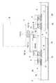
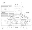
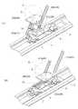
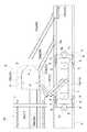
この第1実施形態の物品搬送装置は、図1〜図3に示すように、物品Bを載置支持する複数の物品載置体2を設けて、水平方向またはほぼ水平方向に沿って循環回動する無端回動帯1にて構成されている。前記物品載置体2は、無端回動帯1の長手方向に間隔を隔てて並びかつ無体回動帯1と一体移動するように設けられている。
図1は、物品搬送装置の全体平面図であり、図2は、物品搬送装置の要部を示す平面図であり、図3は、物品搬送装置の要部を示す斜視図である。An embodiment of an article conveying device according to the present invention will be described with reference to the drawings.
[First Embodiment]
First, the first embodiment will be described.
As shown in FIGS. 1 to 3, the article transporting apparatus according to the first embodiment is provided with a plurality of
FIG. 1 is an overall plan view of the article transport apparatus, FIG. 2 is a plan view showing a main part of the article transport apparatus, and FIG. 3 is a perspective view showing a main part of the article transport apparatus.
そして、無端回動帯1の回動経路中には、例えば、物品Bを保管する物品保管設備など各種の物品処理設備に対して物品Bを受け渡すための物品受渡箇所3と、物品処理設備から物品Bを受け取るための物品受取箇所4とが配設されている。この実施形態では、無端回動帯1の回動方向(図1中矢印方向)において、物品受渡箇所3を物品受取箇所4よりも上流側に位置させかつ物品受渡箇所3と物品受取箇所4とを隣接させる状態で配置している。 And in the rotation path | route of the endless rotation belt | band |
前記物品受渡箇所3には、物品載置体2から物品Bを受け渡される物品受取用載置部としての受取用ローラコンベヤ28が設けられている。そして、この受取用ローラコンベヤ28は、物品載置体2から受け渡される物品Bを物品受渡箇所3から物品取出箇所27に向けて水平または水平方向に搬送するように構成されている。
そして、受取用ローラコンベヤ28から物品取出箇所27に物品Bを搬送する取出ローラコンベヤ42が設けられている。
このようにして、物品載置体2から物品Bを受け渡される物品受渡箇所3に位置する物品Bを物品取出箇所27に向けて水平またはほぼ水平方向に搬送する物品載置搬送手段28が、受取用ローラコンベヤ28と取出ローラコンベヤ42とから構成されている。
前記物品取出箇所27は、物品処理設備に対して物品搬送装置から物品Bを取り出すための箇所であり、例えば、物品処理設備側に設置された物品移載装置が物品取出箇所27に搬送された物品Bを取り出すように構成されている。The
A take-out
In this way, the article placing and conveying
The article take-out
前記物品受取箇所4には、物品Bを載置支持する物品受取用載置部としての受渡用ローラコンベヤ35を備え、その受渡用ローラコンベヤ35から物品載置体2に物品Bを受け渡す物品受渡手段23が設けられている。
そして、物品受入箇所38から物品受渡手段23の受渡用ローラコンベヤ35に物品Bを搬送する受入ローラコンベヤ39が設けられている。
前記物品受入箇所38は、物品処理設備から物品搬送装置に物品Bを受け入れるための箇所であり、例えば、物品処理設備側に設置された物品移載装置が受入ローラコンベヤ39に対して物品Bを移載するように構成されている。The
And the receiving
The
前記受取用ローラコンベヤ28、取出ローラコンベヤ42、受入ローラコンベヤ39、受渡用ローラコンベヤ35は、無端回動帯1よりも外側において、無端回動帯1の回動方向と平行に一直線上に並ぶように配設されている。
そして、受取用ローラコンベヤ28、取出ローラコンベヤ42、受入ローラコンベヤ39、受渡用ローラコンベヤ35のいずれのコンベヤも、図2および図3に示すように、左右のローラの間に物品載置体2を位置させることができるように左右のローラの間隔が設定されており、その左右のローラにて物品Bの両端部を載置支持する状態で物品Bを搬送するように構成されている。The receiving
Each of the receiving
このようにして、物品Bを物品載置体2にて載置支持させた状態で環状の搬送経路に沿って搬送し、物品受渡箇所3において物品載置体2から受取用ローラコンベヤ28に物品Bを取り出したのち、その物品Bを受取用ローラコンベヤ28および取出ローラコンベヤ42にて物品取出箇所27に搬送する。また、物品受入箇所38にて受け入れた物品Bを受入ローラコンベヤ39から物品受渡手段23の受渡用ローラコンベヤ35に搬送し、その物品Bを物品受取箇所4において物品受渡手段23が受渡用ローラコンベヤ35から物品載置体2に積み込み、物品載置体2にて載置支持させた状態で環状の搬送経路に沿って搬送する。 In this manner, the article B is conveyed along the annular conveyance path in a state where the article B is placed and supported by the
前記無端回動帯1は、外側と内側との一対のガイドレール5にて案内される複数の走行体6とその走行体6どうしを連結する複数の連結体7とから構成されている。
前記走行体6は、図4〜図7に示すように、二つの板状部材を組み合わせて一つの走行体6を形成しており、複数の走行体6の夫々には、水平軸心周りで回転自在な複数の走行ローラ8と上下軸心周りで回転自在な複数の振止ローラ9とが設けられている。前記ガイドレール5には、走行ローラ8を案内する走行案内面5aと振止ローラ9を案内する振止案内面5bとが形成されている。
図4は、無端回動帯1の要部を示す斜視図であり、図5は、無端回動帯1の要部を示す側断面図であり、図6は、無端回動帯1の要部を示す平面図であり、図7は、無端回動帯1の回動方向に対する反対方向視での無端回動帯1の断面図である。The
As shown in FIGS. 4 to 7, the traveling
4 is a perspective view showing the main part of the
前記無端回転帯1は、マグネット10と一次コイル11とからなるリニアモータにより推進力を得てその長手方向に回動駆動するように構成されている。そして、マグネット10は、ガイドレール5の長手方向に間隔を隔てて複数配置されており、それら複数のマグネット10の夫々が、ガイドレール5に取り付けられたマグネット支持ブラケット29により支持されている。また、一次コイル11は、マグネット10に近接対向するように走行体6の下面部に設けられている。 The endless
複数の連結体7の夫々には、物品Bの横幅よりも短い横幅を有する板状の物品載置体2が一つずつ配置され、その物品載置体2を支持する物品載置体移動用支持手段が設けられている。
そして、物品載置体移動用支持手段は、物品載置体2を、物品載置用姿勢に維持した状態で、図4(イ)に示す搬送用位置と図4(ロ)に示す離間位置とに移動自在にかつ昇降自在に無端回動帯1に対して支持するように構成されている。A plate-like
Then, the article placement body moving support means keeps the
前記物品載置用姿勢は、水平またはほぼ水平な姿勢であり、物品Bの姿勢を水平またはほぼ水平として載置支持するための姿勢である。そして、物品載置体2に載置支持される物品Bは、位置決めピンWにより位置決めされた状態で載置支持されている。
前記搬送用位置は、無端回動帯1における連結体7の上方位置であり、無端回動帯1に対して物品載置体2を接近位置させる位置である。
前記離間位置は、図6および図7に示すように、搬送用位置から水平方向に無端回動帯1よりも外側に間隔を隔てた位置であり、搬送用位置の物品載置体2にて載置支持される物品Bが搬送に伴って占有する物品搬送用空間から外れた位置に物品載置体2を位置させる位置である。そして、図2および図3に示すように、受取用ローラコンベヤ28、取出ローラコンベヤ42、受入ローラコンベヤ39、受渡用ローラコンベヤ35は、離間位置に対応して配設されている。The article placement posture is a horizontal or substantially horizontal posture, and is a posture for placing and supporting the article B with the posture of the article B being horizontal or substantially horizontal. The article B placed and supported on the
The transfer position is a position above the
As shown in FIG. 6 and FIG. 7, the separation position is a position spaced apart from the
前記物品載置体移動用支持手段は、物品載置体2を昇降自在に支持する昇降支持手段13と、物品載置体2を無端回動帯1に対して搬送用位置と離間位置とに移動自在に支持すべく、昇降支持手段13を無端回動帯1に対して移動自在に支持する昇降支持手段移動用支持手段14とから構成されている。 The article placement body moving support means includes an elevation support means 13 that supports the
まず、昇降支持手段13について説明を加えると、この昇降支持手段13は、図5および図7に示すように、物品載置体2に連結された延設体15を、その姿勢を維持した状態で基体16に対して昇降自在に支持するように構成されている。そして、昇降支持手段13は、延設体15に対して水平軸心回りで揺動自在に連結されかつ基体16に対して水平軸心回りで揺動自在に連結された昇降リンクアーム17を上下左右に合計四つ設けた平行リンク機構にて構成されている。
前記延設体15は、物品載置体2の中央位置またはほぼ中央位置から下方側に延びる形状に形成され、水平方向および上下方向において物品載置体2と一体移動するように設けられている。前記基体16は、延設体15と対向する状態で上下方向に延びる形状に形成され、水平方向において物品載置体2と一体移動するように設けられている。First, the lift support means 13 will be described. The lift support means 13 maintains the posture of the
The
次に、昇降支持手段移動用支持手段14について説明を加えると、この昇降支持手段移動用支持手段14は、図4〜図7に示すように、基体16をその姿勢を維持した状態で連結体7に対して水平移動自在に支持するように構成されている。そして、昇降支持手段移動用支持手段14は、連結体7に対して上下軸心周りで揺動自在に連結された一対の第一リンクアーム18と、基体16に対して上下軸心周りで揺動自在に連結された一対の第二リンクアーム19とを枢支連結した平行リンク機構にて構成されている。 Next, the lifting / lowering support means moving support means 14 will be described. As shown in FIGS. 4 to 7, the lifting / lowering support means moving support means 14 is connected to the
前記物品受渡箇所3および物品受取箇所4において、複数の物品載置体2のうちの物品移載対象とする物品載置体2を搬送用位置から離間位置に移動させかつ離間位置から搬送用位置に移動させるように、物品載置体2と一体移動するように設けた被案内部を案内する案内手段21が設けられている。
そして、案内手段21は、物品受渡箇所3において離間位置に位置する物品移載対象の物品載置体2に支持された物品Bを受取用ローラコンベヤ28よりも上方に位置する状態から下降させることによって受取用ローラコンベヤ28に受け渡すべく、物品受渡箇所3において離間位置に位置された物品移載対象の物品載置体2を昇降させるように構成されている。
また、物品受渡箇所3にて受け渡す物品Bを載置支持している物品載置体2、および、物品受取箇所4にて物品Bを受け取る空の物品載置体2を、物品移載対象の物品載置体2としている。In the
Then, the guide means 21 lowers the article B supported by the
Further, the
このように案内手段21は、水平方向において搬送用位置と離間位置との間で物品載置体2を移動させ、かつ、上下方向において受取用ローラコンベヤ28よりも上方と下方との間で離間位置に位置する物品載置体2を昇降させるように構成されている。ちなみに、受取用ローラコンベヤ28よりも上方または下方は、受取用ローラコンベヤ28のローラを基準にしており、例えば、受取用ローラコンベヤ28よりも上方は、受取用ローラコンベヤ28のローラよりも上方である。
そして、案内手段21は、物品載置体2を搬送用位置と離間位置との間で移動させるべく、物品載置体2と一体移動するように設けた水平ガイドローラ20を案内する移動用案内体としての案内レール24と、物品受渡箇所3において離間位置に位置された物品載置体2を昇降させるべく、物品載置体2と一体昇降するように設けた昇降用ガイドローラ25を案内する昇降用案内体としての昇降レール26とから構成されている。In this way, the guide means 21 moves the
The guiding means 21 guides the
まず、案内レール24が水平ガイドローラ20を案内することにより、物品載置体2を搬送用位置と離間位置との間で移動させる構成について説明する。
前記水平ガイドローラ20は、図7に示すように、無端回動帯1の回動方向に対する反対方向視において左側と右側とに一つずつ合計二つ設けられている。そして、二つの水平ガイドローラ20の夫々が、基体16に対して上下軸心周りで回動自在に設けられている。前記基体16は、昇降リンクアーム17が連結された上方側部分よりも下方側の下方側部分が二股に分割された形状に形成されており、その分割された先端部の夫々に水平ガイドローラ20が配置されている。
この実施形態では、無端回動帯1の回動方向に対する反対方向視において、右側(無端回動帯1において内側)に位置する水平ガイドローラ20を第一水平ガイドローラ20aとし、左側(無端回動帯1において外側)に位置する水平ガイドローラ20を第二水平ガイドローラ20bとする。
前記案内レール24は、図2、図3および図6に示すように、水平ガイドローラ20を水平方向で案内する凹溝状に形成され、無端回動帯1よりも外側に配設されている。そして、案内レール24は、無端回動帯1から斜め外側に離れる分岐部分24aと、無端回動帯1の回動方向と水平方向に間隔を隔てた状態で平行な離間用部分24bと、無端回動帯1に対して斜め内側に近づく合流部分24cとから構成されている。また、案内レール24が、二つの水平ガイドローラ20のうち、第一水平ガイドローラ20aを案内するように構成されている。First, a configuration in which the
As shown in FIG. 7, a total of two
In this embodiment, the
As shown in FIGS. 2, 3, and 6, the
前記案内レール24の分岐部分24aが第一水平ガイドローラ20aを案内することにより、物品受取箇所3の手前箇所において物品移載対象の物品載置体2を搬送用位置から離間位置に移動させる。前記案内レール24の離間用部分24bが第一水平ガイドローラ20aを案内することにより、物品受渡箇所3および物品受取箇所4において、物品移載対象の物品載置体2を離間位置に位置させる。前記案内レール24の合流部分24cが第一水平ガイドローラ20aを案内することにより、物品受取箇所4を通過した物品移載対象の物品載置体2を離間位置から搬送用位置に移動させる。
このようにして、案内レール24が第一水平ガイドローラ20aを案内することにより、物品受渡箇所3の手前箇所で物品移載対象の物品載置体2を搬送用位置から離間位置に移動させ、物品受渡箇所3および物品受取箇所4において物品移載対象の物品載置体2を離間位置に位置させ、物品受取箇所4を通過すると物品移載対象の物品載置体2を離間位置から搬送用位置に移動させる。The
In this way, the
そして、物品受渡箇所3において、物品移載対象の物品載置体2を搬送用位置から離間位置に移動させかつ離間位置から搬送用位置に移動させる物品受渡箇所3に対応する案内手段と、物品受取箇所4において、物品移載対象の物品載置体2を搬送用位置から離間位置に移動させかつ離間位置から搬送用位置に移動させる物品受取箇所4に対応する案内手段とを、一つの案内レール24にて兼用するように構成されている。 And in the
前記物品移載対象の物品載置体2については、案内レール24の案内によって、搬送用位置から離間位置に移動させて、物品受渡箇所3および物品受取箇所4において物品載置体2を離間位置に位置させるわけであるが、物品移載対象の物品載置体2以外の物品載置体2については、物品受渡箇所3および物品受取箇所4において物品載置体2を搬送用位置のままに維持させる。
そこで、案内レール24は、物品載置体2が搬送用位置と離間位置との間の分岐用中間位置に位置すると、第一水平ガイドローラ20aを案内して物品載置体2を分岐用中間位置から離間位置に移動させ、かつ、物品載置体2が搬送用位置に位置すると、第一水平ガイドローラ20aを案内せずに物品載置体2を搬送用位置に維持するように構成されている。
そして、無端回動帯1の回動方向において案内レール24が第一水平ガイドローラ20aを案内するよりも手前箇所には、搬送用位置に位置する物品載置体2を分岐用中間位置に移動させる分岐状態と、搬送用位置に位置する物品載置体2をその搬送用位置に維持させる非分岐状態とに切換自在な分岐用切換手段40が設けられている。The
Therefore, the
Then, the
前記分岐用切換手段40は、搬送用位置に位置する物品載置体2を搬送用位置から分岐用中間位置に移動させる案内位置(図2中実線)と非案内位置(図2中点線)とに水平移動自在な分岐用案内レール40aにて構成されている。
前記案内位置は、分岐用案内レール40aの始端部分を搬送用位置に位置する物品載置体における第二水平ガイドローラ20bが通過する位置に位置させて、分岐用案内レール40aが第二水平ガイドローラ20bを案内するための位置である。
前記非案内位置は、分岐用案内レール40aの始端部分を搬送用位置に位置する物品載置体における第二水平ガイドローラ20bが通過する位置よりも外側に退避した位置に位置させて、搬送用位置に位置する物品載置体における第二水平ガイドローラ20bをそのまま通過させるための位置である。The branch switching means 40 includes a guide position (solid line in FIG. 2) and a non-guide position (dotted line in FIG. 2) for moving the
The guide position is such that the start end portion of the
The non-guide position is located at a position where the start end portion of the branching
前記分岐用切換手段40は、図8(イ)に示すように、分岐用案内レール40aを案内位置に位置させて分岐状態に切り換えると、第二水平ガイドローラ20bが分岐用案内レール40aにて案内され、図8(ロ)に示すように、搬送用位置に位置する物品載置体2を分岐用中間位置に移動させる。すると、引き続いて、第一水平ガイドローラ20aが案内レール24にて案内され、図9(イ)に示すように、分岐用中間位置に位置する物品載置体2を離間位置に移動させる。このようにして、物品受渡箇所3および物品受取箇所4において物品載置体2を離間位置に位置させる。 As shown in FIG. 8 (a), when the branching
また、図示は省略するが、分岐用切換手段40は、分岐用案内レール40aを非案内位置に位置させて非分岐状態に切り換えると、第二水平ガイドローラ20bが分岐用案内レール40aにて案内されず、搬送用位置に位置する物品載置体2をそのまま搬送用位置に位置させる。そして、第一水平ガイドローラ20aも案内レール24にて案内されないので、搬送用位置に位置する物品載置体2をそのまま搬送用位置に位置させる。このようにして、物品受渡箇所3および物品受取箇所4において物品載置体2を搬送用位置に位置させる。 Although not shown, when the branching switching means 40 places the branching
そして、分岐用切換手段40は、通常、分岐用案内レール40aを非案内位置に位置させて非分岐状態に切り換えてあり、物品移載対象の物品載置体2が移動してきたときのみ、分岐用駆動部40bにて分岐用案内レール40aを非案内位置から案内位置に水平移動させて、分岐状態に切り換えるように構成されている。 The branching switching means 40 normally switches the branching
前記物品受取箇所4において、離間位置に位置する物品載置体2が通過することによりその物品載置体2を離間位置から搬送用位置に移動させる際には、案内レール24が、搬送用位置に位置する物品載置体2の移動を妨げないようにしながら、第一水平ガイドローラ20aを案内することが必要である。
したがって、図2および図3に示すように、案内レール24の合流部分24cの終端部分を搬送用位置に位置する物品載置体2よりも無端回動帯1の外側に位置させて、案内レール24が搬送用位置に位置する物品載置体2の移動を妨げないようにしている。このようにすると、案内レール24の合流部分24cが第一水平ガイドローラ20aを案内することにより、離間位置に位置する物品載置体2を離間位置と搬送用位置との間の合流用中間位置までしか移動させることができない。
そこで、案内レール24の合流部分24cが第一水平ガイドローラ20aを案内し終えた箇所には、合流用中間位置に位置する物品載置体2を搬送用位置に移動させる合流状態と、搬送用位置に位置する物品載置体2の移動を妨げないように退避する退避状態とに切換自在な合流用切換手段41が設けられている。When the
Therefore, as shown in FIG. 2 and FIG. 3, the
Therefore, at the location where the merging
前記合流用切換手段41は、合流用中間位置に位置する物品載置体2を合流用中間位置から搬送用位置に移動させる案内位置(図2中点線)と退避位置(図2中実線)とに水平移動自在な合流用案内レール41aにて構成されている。
前記案内位置は、図10に示すように、合流用案内レール41aの終端部分を無端回動帯1まで突出させて、合流用案内レール41aが第二水平ガイドローラ20bを案内することにより物品載置体2を搬送用位置に移動させるための位置である。
前記退避位置は、合流用案内レール41aの終端部分を無端回動帯1よりも外側に位置させて、合流用案内レール41aが搬送用位置に位置する物品載置体2と干渉しないようにして、搬送用位置に位置する後続の物品載置体2の移動を妨げないようにするための位置である。The merging switching means 41 includes a guide position (dotted line in FIG. 2) and a retreat position (solid line in FIG. 2) for moving the
As shown in FIG. 10, the guide position is such that the end portion of the merging
The retracted position is such that the end portion of the merging
そして、合流用切換手段41は、合流用案内レール41aを案内位置に位置させて合流状態に切り換え、かつ、合流用案内レール41aを退避位置に位置させて退避状態に切り換えるように構成されている。
また、合流用切換手段41は、通常、合流用案内レール41aを退避位置に位置させて退避状態に切り換えてあり、離間位置に位置する物品載置体2が移動してきたときのみ、合流用駆動部41bにて合流用案内レール41aを退避位置から案内位置に水平移動させて、合流状態に切り換えるように構成されている。The merging switching means 41 is configured to switch the merging
Further, the merging switching means 41 normally switches the merging
次に、昇降レール26が昇降用ガイドローラ25を案内することにより、離間位置に位置する物品載置体2を昇降させる構成について説明する。
前記昇降用ガイドローラ25は、図5および図7に示すように、物品載置体2の中央位置またはほぼ中央位置に配置させるべく、延設体15の下方に配置され、水平軸心回りで回動自在に設けられている。
前記昇降レール26は、図2、図3、図6および図7に示すように、離間位置に位置する物品載置体2における昇降用ガイドローラ26を案内するものである。そして、昇降レール26は、平面視において、離間位置に対応して配設される受取用ローラコンベヤ28、取出ローラコンベヤ42、受入ローラコンベヤ39、受渡用ローラコンベヤ35の全長よりも長い直線状に形成され、かつ、これら各ローラコンベヤにおいて水平方向の中央位置またはほぼ中央位置に位置するように配置されている。
前記昇降レール26は、図11に示すように、側面視において、その始端側から順に、平坦状の始端部分26a、終端側ほど上方側に位置するように傾斜する上昇部分26b、平坦状の中間部分26c、終端側ほど下方側に位置するように傾斜する下降部分26d、平坦状の終端部分26eにて構成されている。
そして、昇降レール26は、昇降用ガイドローラ25に対して下方側から接当して昇降用ガイドローラ25を上下方向に案内するように構成されている。Next, the structure which raises / lowers the
As shown in FIGS. 5 and 7, the elevating
As shown in FIGS. 2, 3, 6, and 7, the elevating
As shown in FIG. 11, the elevating
The elevating
前記始端部分26aが昇降用ガイドローラ25を案内することにより、図11(イ)に示すように、物品移載対象の物品載置体2に支持される物品Bを受取用ローラコンベヤ28よりも下方に位置させる。前記上昇部分26bが昇降用ガイドローラ25を案内することにより、図11(ロ)に示すように、物品移載対象の物品載置体2を徐々に上昇させ最終的に受取用ローラコンベヤ28よりも上方に位置させて、物品移載対象の物品載置体2が支持する物品Bを受取用ローラコンベヤ28よりも上方に位置させた状態で物品移載対象の物品載置体2を受取用ローラコンベヤ28に対して接近させる。前記中間部分26cが昇降用ガイドローラ25を案内することにより、物品移載対象の物品載置体2を受取用ローラコンベヤ28よりも上方に位置させた状態を維持する。前記下降部分26dが昇降用ガイドローラ25を案内することにより、図11(ハ)に示すように、物品移載対象の物品載置体2を受取用ローラコンベヤ28よりも上方から徐々に下降させ最終的に物品移載対象の物品載置体2を受取用ローラコンベヤ28よりも下方に位置させる。 When the
このようにして、昇降レール26が昇降用ガイドローラ25を案内することにより、物品受渡箇所3において離間位置に位置する物品移載対象の物品載置体2に支持された物品Bを、受取用ローラコンベヤ28よりも上方に位置させた状態で受取用ローラコンベヤ28に接近させ、その後、物品移載対象の物品載置体2を徐々に下降させて最終的に受取用ローラコンベヤ28よりも下方まで下降させて、物品移載対象の物品載置体2に支持された物品Bを受取用ローラコンベヤ28に受け渡す。 In this way, the elevating
前記物品受渡箇所3において物品移載対象の物品載置体2から受取用ローラコンベヤ28に受け渡すときには、まず、案内レール24の案内によって、物品移載対象の物品載置体2を離間位置に位置させて、その物品移載対象の物品載置体2を受取用ローラコンベヤ25と上下方向に重複する状態で位置させることになる。このように、物品移載対象の物品載置体2を受取用ローラコンベヤ25と上下方向に重複する状態で位置させることで、昇降レール26の案内によって、物品移載対象の物品載置体2を昇降させるだけで、物品移載対象の物品載置体2から受取用ローラコンベヤ28への物品Bの受け渡しを行うことができることになる。
そして、このとき、物品移載対象の物品載置体2が移動する移動距離は、物品移載対象の物品載置体2から受取用ローラコンベヤ28への物品Bの受け渡しのために物品移載対象の物品載置体2を昇降させるだけの距離となり、物品受渡箇所3での物品の受け渡しを行うための構成の小型化および簡素化を図ることができる。
しかも、昇降レール26が昇降用ガイドローラ25を案内するという簡易な構成としながら、物品受渡箇所3には、単に、受取用ローラコンベヤ28を設置するだけで、物品移載対象の物品載置体2から受取用ローラコンベヤ28への物品Bの受け渡しを行うことができることとなって、物品受渡箇所3での物品の受け渡しを行うための構成の簡素化を一層図ることができる。When the article is transferred from the
At this time, the moving distance of the
In addition, while the simple structure in which the elevating
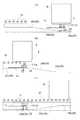
図12に示すように、受取用ローラコンベヤ28と取出ローラコンベヤ42とから構成された物品載置搬送手段22は、物品載置体2から受け渡された物品Bを物品受渡箇所3から物品取出箇所27に水平または水平方向に搬送するわけであるが、物品受渡箇所3と物品取出箇所27との間に複数の物品Bを載置可能に構成されている。 As shown in FIG. 12, the article placement / conveying
前記受取用ローラコンベヤ28は、物品載置体2から受け渡された物品Bを無端回動帯1の回動方向に対して平行またはほぼ平行に搬送するように構成されている。そして、取出ローラコンベヤ42は、受取用ローラコンベヤ28にて搬送された物品Bの搬送方向を90度変更可能に構成されている。
前記取出ローラコンベヤ42は、第一上下軸心P1周りで旋回可能に構成されており、この旋回によって受取用ローラコンベヤ28から搬送された物品Bの搬送方向を90度変更して、物品Bを物品取出箇所27に搬送するように構成されている。The receiving
The take-out
前記受取用ローラコンベヤ28では、物品載置体2から物品Bを受け取る箇所よりも搬送方向の下流側に二つの物品Bを載置可能であり、取出ローラコンベヤ42では、一つの物品Bを載置可能である。このようにして、物品受渡箇所3にて物品載置体2から受け渡された物品Bを、物品受渡箇所3と物品取出箇所27との間に最大三つの物品Bを載置可能としている。
そして、受取用ローラコンベヤ28と取出ローラコンベヤ42とは、物品受渡箇所4にて物品載置体2から受け渡された物品Bを、物品受渡箇所3と物品取出箇所27との間に載置しながら順次物品取出箇所27側に移動させる形態で、物品取出箇所27に搬送するように構成されている。In the receiving
The receiving
図13に示すように、受入ローラコンベヤ39は、第二上下軸心P2周りで旋回可能に構成されており、この旋回によって、物品受入箇所38にて受け入れた物品Bを物品受渡手段23の受渡用ローラコンベヤ35に搬送できるように構成されている。
前記物品受渡手段23は、受入ローラコンベヤ39から物品Bが搬送されると、物品受取箇所4において離間位置に位置される物品載置体2に物品受取用載置部に載置支持された物品Bを受け渡すように構成されている。
そして、物品受渡手段23は、受渡用ローラコンベヤ35を物品受取箇所4において離間位置に位置する物品載置体2の動きに同期させて移動させ、かつ、受渡用ローラコンベヤ35に支持された物品Bを物品受取箇所4において離間位置に位置する物品載置体2よりも上方に位置する状態から下降させることによって物品載置体2に受け渡すべく、受渡用ローラコンベヤ35を昇降させるように構成されている。As shown in FIG. 13, the receiving
When the article B is transported from the receiving
Then, the article delivery means 23 moves the
前記物品受渡手段23は、図14に示すように、受渡用ローラコンベヤ35を固定支持する昇降枠体34、その昇降枠体34を上下方向に昇降自在に片持ち支持しかつ無端回動帯1の回動方向においてガイド体30の長手方向に沿って往復移動可能な往復移動枠体32などから構成されている。前記ガイド体30は、図3に示すように、物品受取箇所4の全長にわたって設置されている。
そして、図示は省略するが、往復移動枠体32をガイド体30の長手方向に往復移動させる往復移動用モータ、昇降枠体34を昇降させる昇降用モータなども設けられている。As shown in FIG. 14, the article delivery means 23 is a
Although not shown, a reciprocating motor for reciprocating the
この物品受渡手段23の動作について説明すると、まず、受入ローラコンベヤ39から受渡用ローラコンベヤ35に物品Bが搬送されると、受渡用ローラコンベヤ35の作動を停止し、受渡用ローラコンベヤ35にて物品Bを載置支持した状態とし、受渡用ローラコンベヤ35が支持する物品Bを物品載置体2よりも上方に位置させるべく、昇降枠体34を往復移動枠体32に対して上昇させておくことによって、離間位置に位置する物品載置体2の移動軌跡と上下方向では重複する状態で物品載置体2の移動と同期して移動させるための開始位置に受渡用ローラコンベヤ35を待機させておく。
そして、物品移載対象の物品載置体2が移動の開始位置に対応する位置に到達すると、図15(イ)および(ロ)に示すように、その物品載置体2の動きに同期させて往復移動枠体32を移動させ、かつ、受渡用ローラコンベヤ35を物品載置体2よりも上方から徐々に下降させ最終的に物品載置体2よりも下方まで下降させるべく、昇降枠体34を下降させる。The operation of the article delivery means 23 will be described. First, when the article B is transported from the
Then, when the
このようにして、物品受渡手段23が、物品載置体2の動きに同期させて受取用ローラコンベヤ35を移動させた状態で、その受取用ローラコンベヤ35を下降させるだけで、受取用ローラコンベヤ35から移載対象の物品載置体2に物品Bを積み込むことができることになる。
そして、このとき、受取用ローラコンベヤ35を物品移載対象の物品載置体2の移動に同期させて移動させる移動距離が、受取用ローラコンベヤ35から移載対象の物品載置体2に物品Bを積み込むために受取用ローラコンベヤ35を下降させるだけの距離となり、物品受渡手段23の構成の小型化および簡素化を図ることができる。In this way, the article delivery means 23 moves the receiving
At this time, the moving distance by which the receiving
以下、この物品搬送装置の動作を説明する。
この物品搬送装置は、図外の制御手段によりその動作が制御されるわけであるが、この制御手段は、無端回動帯1における物品載置体2の現在位置、および、どの物品載置体2にどの物品Bを載置支持されているかなどの各種の情報を管理しており、この管理した情報に基づいて、物品搬送装置の動作を制御するように構成されている。Hereinafter, the operation of the article conveying apparatus will be described.
The operation of the article transporting apparatus is controlled by a control means (not shown). This control means determines the current position of the
まず、物品受渡箇所3にて物品載置体2から受取用ローラコンベヤ28に物品Bを受け渡す場合について説明する。
前記無端回動帯1を循環回動させている状態において、物品移載対象の物品載置体2が分岐用切換手段40よりも手前に位置する分岐用設定位置に達すると、その分岐用切換手段40を非分岐状態から分岐状態に切り換える。すると、図8および図9に示すように、分岐用案内レール41aによる第二水平ガイドローラ20bの案内、および、案内レール24による第一水平ガイドローラ20aの案内によって、物品受渡箇所3よりも手前箇所において、搬送用位置に位置する物品移載対象の物品載置体2を搬送用位置から離間位置に移動させる。その後、図11に示すように、昇降レール26による昇降用ガイドローラ25の案内によって、物品移載対象の物品載置体2は、水平方向では受取用ローラコンベヤ28と上下方向に重複する離間位置に位置しかつ上下方向では支持している物品Bを受取用ローラコンベヤ28よりも上方に位置させた状態で、受取用ローラコンベヤ28に対して接近する。First, the case where the article B is delivered from the
In the state where the
そして、昇降レール26による昇降用ガイドローラ25の案内によって、物品移載対象の物品載置体2は、受取用ローラコンベヤ28よりも下方に下降されて、支持している物品Bを受取用ローラコンベヤ28に受け渡す。
その後、物品移載対象の物品載置体2が物品受取箇所4を通過したのち合流用切換手段41よりも手前に位置する合流用設定位置に達すると、その合流用切換手段41を退避状態から合流状態に切り換える。すると、図10に示すように、案内レール24による第一水平ガイドローラ20aの案内、および、合流用案内レール41aによる第二水平ガイドローラ20bの案内によって、離間位置に位置する物品移載対象の物品載置体2を離間位置から搬送用位置に移動させる。Then, by the guide of the raising / lowering
After that, when the
このようにして、物品受渡箇所3にて物品移載対象の物品載置体2から受取用ローラコンベヤ28に物品Bを受け渡すわけであるが、この物品受渡箇所3における物品移載対象の物品載置体2から受取用ローラコンベヤ28への物品Bの受け渡しを連続的に行うことができる。
説明を加えると、受取用ローラコンベヤ28および取出コンベヤ42は、物品受渡箇所3において物品移載対象の物品載置体2から受け渡された物品Bを、物品受渡箇所3と物品取出箇所27との間に載置させながら順次物品取出箇所27側に搬送する。したがって、受取用ローラコンベヤ28には、物品移載対象の物品載置体2から物品Bを受け渡されても、その物品Bは順次物品取出箇所27側に搬送され、次の物品移載対象の物品載置体2から物品Bを受け取るだけのスペースを確保できることになる。
そして、案内レール24の案内によって、複数の物品移載対象の物品載置体2を連続して搬送用位置から離間位置に移動させて、物品受渡箇所3における物品移載対象の物品載置体2から受取用ローラコンベヤ28への物品Bの受け渡しを連続的に行うようにしている。
前記受取用ローラコンベヤ28は、物品受渡箇所3において物品載置体2から受け渡された物品Bを、物品取出箇所27にて物品Bが取り出されるごとに順次物品取出箇所27側に移動させる形態で、取出ローラコンベヤ42に搬送する。そして、取出ローラコンベヤ42は、旋回によって受取用ローラコンベヤ28から搬送された物品Bを物品取出箇所27に搬送する。In this way, the article B is delivered from the
In other words, the receiving
Then, by the guidance of the
The receiving
次に、物品受取箇所4にて受渡用ローラコンベヤ35から物品載置体2に物品Bを積み込む場合について説明する。
この場合には、まず、図13に示すように、受入ローラコンベヤ39および物品受渡手段23の受渡用ローラコンベヤ35によって、物品受入箇所38にて受け入れた物品Bを受渡用ローラコンベヤ35に載置支持させる。そして、物品受渡手段23が、受渡用ローラコンベヤ35が支持する物品Bを、離間位置に位置する物品移載対象の物品載置体2の移動軌跡と上下方向に重複する状態でその物品移載対象の物品載置体2よりも上方に位置させるように受渡用ローラコンベヤ35を待機させておく。Next, a case where the article B is loaded from the
In this case, first, as shown in FIG. 13, the article B received at the
前記物品受渡箇所3にて物品載置体2から受取用ローラコンベヤ28に物品Bを受け渡す場合と同様に、無端回動帯1を循環回動させている状態において、物品移載対象の物品載置体2が分岐用切換手段40よりも手前に位置する分岐用設定位置に達すると、分岐用切換手段40を非分岐状態から分岐状態に切り換え、物品受渡箇所3よりも手前箇所において、搬送用位置に位置する物品載置体2を搬送用位置から離間位置に移動させる。
その後、離間位置に位置する物品移載対象の物品載置体2が離間位置に位置したまま物品受渡箇所3を通過して受渡用ローラコンベヤ35の移動の開始位置に対応する位置に到達すると、図15(イ)および(ロ)に示すように、物品受渡手段23が、その物品載置体2の動きに同期させて受渡用ローラコンベヤ35を移動させ、かつ、受渡用ローラコンベヤ35を物品載置体2よりも上方から下方まで下降させて、受渡用ローラコンベヤ35が支持する物品Bを物品載置体2に積み込む。Similar to the case where the article B is delivered from the
Thereafter, when the
また、物品Bを積み込んだ物品移載対象の物品載置体2が物品受取箇所4を通過したのち合流用切換手段41よりも手前に位置する合流用設定位置に達すると、その合流用切換手段41を退避状態から合流状態に切り換え、離間位置に位置する物品載置体2を離間位置から搬送用位置に移動させる。 Further, when the
次に、物品受渡箇所3での物品Bの受け渡しおよび物品受取箇所4での物品Bの受け取りを行わない場合について説明する。
この場合は、無端回動帯1を循環回動させている状態において、物品移載対象の物品載置体2以外の物品載置体2が分岐用切換手段40よりも手前に位置する分岐用設定位置に達しても、分岐用切換手段40を非分岐状態に維持する。すると、分岐用案内レール41aによる第二水平ガイドローラ20bの案内、および、案内レール24による第一水平ガイドローラ20aの案内が行われず、その物品載置体2を搬送用位置に位置させた状態で物品受渡箇所3および物品受取箇所4を通過させる。Next, the case where the delivery of the article B at the
In this case, in the state where the
〔第2実施形態〕
次に、第2実施形態について説明する。
この第2実施形態は、上記第1実施形態において、搬送用位置に位置する物品載置体2を分岐用中間位置に移動させる構成と合流用中間位置に位置する物品載置体2を搬送用位置に移動させる構成との別実施形態であり、これらの構成について詳細に説明し、その他の構成については、詳細な説明は省略する。[Second Embodiment]
Next, a second embodiment will be described.
The second embodiment is configured to move the
まず、搬送用位置に位置する物品載置体2を分岐用中間位置に移動させる構成について説明する。
上記第1実施形態では、図2に示すように、搬送用位置に位置する物品載置体2を搬送用位置から分岐用中間位置に移動させる案内位置と非案内位置とに水平移動自在な分岐用案内レール40aを備えた分岐用切換手段40を設けているが、この第2実施形態では、図16に示すように、搬送用位置に位置する物品載置体2を搬送用位置から分岐用中間位置側に移動させる可動ガイド40bと、この可動ガイド40bにて分岐用中間位置側に移動された物品載置体2を分岐用中間位置まで移動させる分岐中間用案内レール40cとを備えた分岐用切換手段40を設けている。First, the structure which moves the
In the first embodiment, as shown in FIG. 2, the branch is horizontally movable between a guide position for moving the
前記可動ガイド40bは、搬送用位置に位置する物品載置体2を搬送用位置から分岐用中間位置側に移動させる案内位置(図16中点線)と非案内位置(図16中実線)とに上下軸心周りで揺動自在に設けられており、案内位置において、第二水平ガイドローラ20bを分岐用中間位置側に案内するように構成されている。
前記分岐中間用案内レール40cは、搬送用位置に位置する物品載置体2における第二水平ガイドローラ20bが通過する位置よりも外側に退避した位置に固定状態で設置されており、搬送用位置に位置する物品載置体2と干渉することがないように設置されている。The
The branch
前記分岐用切換手段40は、可動ガイド40bを案内位置に位置させて分岐状態に切り換えると、可動ガイド40bが第二水平ガイドローラ20bを分岐用中間位置側に案内して、搬送用位置に位置する物品載置体2を分岐用中間位置側に移動させる。この可動ガイド40bによる案内に引き続き、分岐中間用案内レール40cが第二水平ガイドローラ20bを案内して、物品載置体2が分岐用中間位置まで移動される。
そして、分岐用切換手段40は、可動ガイド40bを非案内位置に位置させて非分岐状態に切り換えると、可動ガイド40bが第二水平ガイドローラ20bを分岐用中間位置側に案内することはなく、搬送用位置に位置する物品載置体2をそのまま搬送用位置に位置させた状態で移動させる。
また、分岐用切換手段40は、通常、可動ガイド40bを非案内位置に位置させて非分岐状態に切り換えてあり、物品移載対象の物品載置体2が移動してきたときのみ、可動ガイド40bを案内位置に位置させて分岐状態に切り換えるように構成されている。When the branching switching means 40 positions the
Then, when the branching switching means 40 positions the
The branch switching means 40 normally switches the
次に、合流用中間位置に位置する物品載置体2を搬送用位置に移動させる構成について説明する。
上記第1実施形態では、図2に示すように、合流用中間位置に位置する物品載置体2を合流用中間位置から搬送用位置に移動させる案内位置と退避位置とに水平移動自在な合流用案内レール41を備えた合流用切換手段41を設けているが、この第2実施形態では、図17に示すように、物品支持体2を搬送用位置または離間位置に位置保持する位置保持手段50を設け、この位置保持手段50の位置保持作用によって、合流用切換手段41を設けることなく、合流用中間位置に位置する物品載置体2を合流用中間位置から搬送用位置に移動させている。Next, the structure which moves the
In the first embodiment, as shown in FIG. 2, the merging is possible to move horizontally between the guide position for moving the
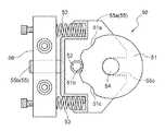
前記位置保持手段50は、図17および図18に示すように、連結体7の裏面部に設けられており、第一リンクアーム18の揺動と一体的に上下軸心周りで回動自在な円形状のカム体51、そのカム体51の外周部に形成された被係合溝51a〜51cに係合する係合ピン52、および、この係合ピン52をカム体51の被係合溝51a〜51cに係合させる側に弾性付勢する一対の弾性体(コイルバネ)53を備えて構成されている。
図17は、物品載置体2を搬送用位置よりも離間位置側に位置させた状態での斜視図を示しており、図18は、位置保持手段50の平面図を示している。As shown in FIGS. 17 and 18, the position holding means 50 is provided on the back surface portion of the
FIG. 17 shows a perspective view in a state where the
前記カム体51は、一対の第一リンクアーム18の一方に対応して設けられ、第一リンクアーム18と連結体7との連結箇所に設けられた上下方向に沿う軸部54と一体的に回動するように設けられている。すなわち、カム体51が、第一リンクアーム18の揺動と一体的に回動するように連係されている。
前記被係合溝51a〜51cは、カム体51の内径側に窪む凹状に形成され、カム体51の周方向に間隔を隔てて三つ設けられている。そして、中央に位置する第二被係合溝51bが搬送用位置に対応しており、側方に位置する第一被係合溝51aと第三被係合溝51cが離間位置に対応している。
前記係合ピン52は、係合ピン支持体55にて上下方向に沿う姿勢で支持されており、係合ピン支持体55は、上下一対の板状部分55aと水平方向に延びるスライド軸部55bとを備えて構成されている。そして、スライド軸部55bが、連結体7の裏面部にボルトにより締結された弾性体用受体56に形成された孔部に対してスライド移動自在に設けられおり、係合ピン支持体55が弾性体用受体56に対してスライド移動自在に支持されている。また、係合ピン支持体55は、上下一対の板状部分55aに形成された凹状の溝部55cを軸部54に係合させた状態で上下一対の板状部分55aにてカム体51を挟み込むように配設されている。
前記弾性体53は、弾性体用受体56と係合ピン支持体55との間に設けられ、係合ピン支持体55を弾性体用受体56から離れる側に付勢している。The
The engaged
The
The
図19〜図21に基づいて、位置保持手段50の位置保持作用によって、合流用中間位置に位置する物品載置体2を合流用中間位置から搬送用位置に移動させるときの動きについて説明する。図19〜図21において、(イ)は物品載置体2の動きについての平面図を示しており、(ロ)は位置保持手段50の動きについての平面図を示している。
図19に示すように、物品載置体2が離間位置に位置するときには、係合ピン52が離間位置に対応する第一係合溝51aまたは第三係合溝51cに係合する。この図19では、係合ピン52が第三係合溝51cに係合する場合を示している。この係合ピン52と第三被係合溝51cとの係合により、物品載置体2を離間位置に位置保持して、その物品載置体2が横方向に振れるのを抑制している。
そして、図20に示すように、案内レール24の合流部分24cによる案内によって、離間位置から合流用中間位置に移動される。このとき、第一リンクアーム18が揺動し、この第一リンクアーム18の揺動と一体的にカム体51が回動する。すると、係合ピン52が、第三被係合溝51cから離脱して、カム体51の外周部を摺動する。
その後、図21に示すように、係合ピン52が、弾性体53の弾性力によって、第二被係合溝51bと係合するようにカム体51の外周部を摺動することになる。この係合ピン52の摺動によってカム体51が図中矢印方向に回動し、このカム体51の回動と一体的に第一リンクアーム18が揺動され、物品載置体2が搬送用位置に移動される。
このようにして、位置保持手段50の位置保持作用によって、合流用中間位置に位置する物品載置体2を合流用中間位置から搬送用位置に移動させている。
また、物品載置体2が搬送用位置に位置するときには、係合ピン52と第二被係合溝51bとの係合により、物品載置体2を搬送用位置に位置保持して、その物品載置体2が横方向に振れるのを抑制している。Based on FIGS. 19 to 21, a movement when the
As shown in FIG. 19, when the
Then, as shown in FIG. 20, the
Thereafter, as shown in FIG. 21, the engaging
In this way, the
When the
〔別実施形態〕
(1)上記第1および第2実施形態では、離間位置を無端回動帯1よりも外側に定め、物品処理設備に対して物品搬送装置から物品Bを取り出す箇所および物品処理設備から物品搬送装置に物品Bを受け入れる箇所として、物品受渡箇所3および物品受取箇所4を用いているが、物品受渡箇所3および物品受取箇所4をどのような用途に用いるかは適宜変更が可能である。[Another embodiment]
(1) In the first and second embodiments described above, the separation position is defined outside the
例えば、図22に示すように、物品受渡箇所および物品受取箇所を、隣接する無端回動帯1どうしでの物品Bの受け渡しおよび物品Bの受け取りの箇所として用いることもできる。
前記物品受渡箇所3と物品受取箇所4とを隣接して配置したものを一つの組として、隣接する無端回動帯1どうしを二つの組にて接続するように設けられている。一つの組は、第一無端回動帯1aから第二無端回動帯1bに物品Bを受け渡すために用い、この物品受渡箇所3および物品受取箇所4を、第一物品受渡箇所3aおよび第一物品受渡箇所4aとする。また、もう一つの組は、第二無端回動帯1bから第一無端回動帯1aに物品Bを受け渡すために用い、この物品受渡箇所3および物品受取箇所4を、第二物品受渡箇所3bおよび第二物品受渡箇所4bとする。
そして、第一物品受渡箇所3aおよび第二物品受渡箇所3bにおいては、上記実施形態と同様に、離間位置に対応して受取用ローラコンベヤ28を設け、案内レール24や昇降レール26なども設けられている。また、第一物品受取箇所4aおよび第二物品受取箇所4bにおいても、上記実施形態と同様に、受渡用ローラコンベヤ35を備えた物品受渡手段23を設けている。For example, as shown in FIG. 22, the article delivery location and the article receipt location may be used as locations for delivery of the product B and reception of the product B between the adjacent
The
And in the 1st
また、図23〜図25に示すように、物品受渡箇所および物品受取箇所を、同じ無端回動帯1において、異なる物品載置体2どうしでの物品Bの受け渡しおよび物品Bの受け取りの箇所として用いることもできる。
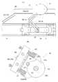
図23は、この別実施形態における物品搬送装置の要部の平面図であり、図24(イ)は、その物品搬送装置の要部の側面図であり、図24(ロ)は、その物品搬送装置の要部の正面図であり、図25は、物品搬送装置の動作を示す平面図である。Further, as shown in FIGS. 23 to 25, the article delivery location and the article receipt location are used as locations for delivery of the product B and delivery of the product B between different
FIG. 23 is a plan view of the main part of the article transport apparatus according to this alternative embodiment, FIG. 24 (a) is a side view of the main part of the article transport apparatus, and FIG. 24 (b) is the article thereof. FIG. 25 is a front view of a main part of the transport apparatus, and FIG. 25 is a plan view showing the operation of the article transport apparatus.
前記無端回動帯1が対向して回動駆動する箇所において、無端回動帯1よりも内側に、無端回動帯1の回動方向に隣接して配置する物品受取箇所3と物品受渡箇所4とを一つの組とし、二つの組を無端回動帯1に対応して位置させるように無端回動帯1が対向する方向に並べて配置する。
図23において上方側から下方側へ無端回動帯1が回動する部分に対応する物品受渡箇所3および物品受取箇所4を、第三物品受渡箇所3cおよび第三物品受取箇所4cとし、図23において下方側から上方側へ無端回動帯1が回動する部分に対応する物品受渡箇所3および物品受取箇所4を、第四物品受渡箇所3dおよび第三物品受取箇所4dとする。
そして、第三物品受渡箇所3cにおいて、離間位置に位置する物品載置体2に支持された物品Bを取り出したのち、第四物品受取箇所4dにおいて、その取り出した物品Bを離間位置に位置する物品載置体2に積み込む取出積込兼用手段43が設けられている。また、この取出積込兼用手段43は、第四物品受渡箇所3dにおいて、離間位置に位置する物品載置体2に支持された物品Bを取り出したのち、第三物品受取箇所4cにおいて、その受け取った物品Bを離間位置に位置する物品載置体2に積み込むこともできるように構成されている。The
In FIG. 23, the
Then, after taking out the article B supported by the
前記取出積込兼用手段43は、左右のローラの間に物品移載対象の物品載置体2を位置させることができかつその左右のローラにて物品Bの両端部を載置支持する状態で物品Bを搬送可能な取出積込兼用ローラコンベヤ44を備えている。そして、取出積込兼用手段43は、第三物品受渡箇所3c、第三物品受取箇所4c、第四物品受渡箇所3d、第四物品受取箇所4dの夫々において、取出積込兼用ローラコンベヤ44を離間位置に位置する物品移載対象の物品載置体2の移動軌跡と上下方向に重複する状態でその物品載置体2の移動方向に移動自在にかつ昇降自在に構成され、かつ、取出積込兼用ローラコンベヤ44を、第三物品受渡箇所3c、第三物品受取箇所4c、第四物品受渡箇所3d、第四物品受取箇所4dの順に循環移動自在に構成されている。
この場合にも、案内レール24や昇降レール26を設けているが、昇降レール26は、平坦状に形成されている。すなわち、昇降レール26にて離間位置に位置する物品移載対象の物品載置体2を昇降させることなく、取出積込兼用手段43が、取出積込兼用ローラコンベヤ44を昇降することにより、第三物品受渡箇所3cおよび第四物品受渡箇所3dにおいて、離間位置に位置する物品移載対象の物品載置体2から取出積込兼用ローラコンベヤ44に物品Bを取り出すようにしている。The take-out and loading means 43 can position the
Also in this case, the
説明を加えると、第三物品受渡箇所3cと第三物品受取箇所4cとの全長にわたっておよび第四物品受渡箇所3dと第四物品受取箇所4dとの全長にわたって取出積込兼用ローラコンベヤ44を移動可能とする前後ガイドレール45と、第三物品受取箇所4cから第四物品受渡箇所3dへおよび第四物品受取箇所4dから第三物品受渡箇所3cへ取出積込兼用ローラコンベヤ44を移動可能とする一対の横行ガイドレール47とを設けている。
そして、前後ガイドレール45は、第三物品受渡箇所3cおよび第三物品受取箇所4cに対応する位置と第四物品受渡箇所3dおよび第四物品受取箇所4dに対応する位置との間で移動すべく、横行ガイドレール47の長手方向に移動自在に設けられている。
また、前後ガイドレール45の長手方向に往復移動自在な前後往復移動体46が設けられ、この前後往復移動体46が、取出積込兼用ローラコンベヤ44を旋回自在にかつ昇降自在に吊り下げ支持している。
図示は省略するが、前後ガイドレール45を横行ガイドレール47の長手方向に移動させるガイドレール用モータ、前後往復移動体46を前後ガイドレール45の長手方向に往復移動させる往復移動用モータなどが設けられ、前後往復移動体46にも、取出積込兼用ローラコンベヤ44を旋回させる旋回モータが設けられている。If explanation is added, the take-out and
The front /
In addition, a back-and-
Although not shown, a guide rail motor for moving the front and
以下、取出積込兼用手段43の動作について、第三物品受渡箇所3cにおいて、離間位置に位置する物品載置体2に支持された物品Bを取り出したのち、第四物品受取箇所4dにおいて、その受け取った物品Bを離間位置に位置する物品載置体2に積み込む場合において説明する。 Hereinafter, regarding the operation of the take-out and loading means 43, after taking out the article B supported by the
前記取出積込兼用手段43は、第三物品受渡箇所3cにおいて、離間位置に位置する物品移載対象の物品載置体2に支持された物品Bを取り出すときには、まず、前後ガイドレール45を第三物品受渡箇所3cおよび第三物品受取箇所4cに対応する位置に位置させた状態で、取出積込兼用ローラコンベヤ44を離間位置に位置する物品移載対象の物品載置体2の移動軌跡と上下方向に重複させる状態でその物品移載対象の物品載置体2が支持する物品Bよりも下方に位置させるべく、取出積込兼用ローラコンベヤ44を移動の開始位置に待機させておく。そして、取出積込兼用手段43は、図25(イ)に示すように、物品移載対象の物品載置体2が取出積込兼用ローラコンベヤ44の移動の開始位置に対応する位置に到達すると、取出積込兼用ローラコンベヤ44を離間位置に位置する物品移載対象の物品載置体2の動きに同期させて移動させるべく、前後往復移動体46を移動させ、かつ、図24(ロ)の実線で示すように、取出積込兼用ローラコンベヤ44を離間位置に位置する物品移載対象の物品載置体2に支持された物品Bよりも下方に位置する状態から上昇させることによって物品Bを取出積込兼用ローラコンベヤ44に取り出すべく、取出積込兼用ローラコンベヤ44を上昇させるように構成されている。 In the third
このようにして、取出積込兼用ローラコンベヤ44に物品Bを取り出すと、図25(ロ)に示すように、前後ガイドレール45を第三物品受渡箇所3cおよび第三物品受取箇所4cに対応する位置から第四物品受渡箇所3dおよび第四物品受取箇所4dに対応する位置に移動させ、かつ、前後往復移動体46が取出積込兼用ローラコンベヤ44を旋回させる。そして、取出積込兼用手段43は、取出積込兼用ローラコンベヤ44に支持された物品Bを第四物品受取箇所4dにおいて離間位置に位置する物品載置体2に積み込むように構成されている。
前記取出積込兼用手段43は、第四物品受取箇所4dにおいて取出積込兼用ローラコンベヤ44に支持された物品Bを離間位置に位置する物品移載対象の物品載置体2に積み込むときには、まず、取出積込兼用ローラコンベヤ44が支持する物品Bを第四物品受取箇所4dにおいて離間位置に位置する物品移載対象の物品載置体2の移動軌跡と上下方向に重複させる状態でその物品移載対象の物品載置体2よりも上方に位置させるべく、取出積込兼用ローラコンベヤ44を移動の開始位置に待機させておく。そして、取出積込兼用手段43は、物品移載対象の物品載置体2が取出積込兼用ローラコンベヤ44の移動の開始位置に対応する位置に到達すると、図25(ハ)に示すように、取出積込兼用ローラコンベヤ44を離間位置に位置する物品移載対象の物品載置体2の動きに同期させて移動させるべく、前後往復移動体46を移動させ、かつ、図24(ロ)の点線で示すように、取出積込兼用ローラコンベヤ44が支持する物品Bを離間位置に位置する物品載置体2よりも上方に位置する状態から下降させることによって取出積込兼用ローラコンベヤ44が支持する物品Bを離間位置に位置する物品載置体2に積み込むべく、取出積込兼用ローラコンベヤ44を下降させるように構成されている。When the article B is taken out to the take-out and
The loading / unloading means 43, when loading the article B supported by the unloading /
(2)上記第1および第2実施形態では、一つの案内レール24が、物品受渡箇所3における案内手段と物品受取箇所4における案内手段とを兼用するようにしているが、例えば、無端回動帯1の回動方向において物品受渡箇所3と物品受取箇所4とを間隔を隔てる状態で配置し、物品受渡箇所3に対応する案内レール24と、物品受取箇所4に対応する案内レール24とを各別に設けて実施することも可能である。(2) In the first and second embodiments, one
(3)上記第1および第2実施形態では、物品受渡箇所3に設置する物品受取用載置部22としての受取用ローラコンベヤ28を設け、昇降レール26の案内によって物品受取箇所3において離間位置に位置する物品移載対象の物品載置体2を昇降させることによって物品移載対象の物品載置体2から受取用ローラコンベヤ28に物品Bを受け渡すようにしているが、物品受取箇所3において離間位置に位置する物品移載対象の物品載置体2を昇降させることなく、物品受渡箇所3に設置する物品受取用載置部を昇降させることによって物品移載対象の物品載置体2から物品受取用載置部に物品Bを取り出すように構成することも可能である。この場合には、例えば、別実施形態(1)で述べた如く、取出積込兼用ローラコンベヤ44を昇降自在に備えた取出積込兼用手段43を物品受渡箇所3に設置する。(3) In the first and second embodiments described above, a receiving
(4)上記第1および第2実施形態では、物品受渡箇所3に物品受取用載置部22としての受取用ローラコンベヤ28を設置し、物品受取箇所4に受渡用ローラコンベヤ35を備えた物品受渡手段23を設置したが、例えば、別実施形態(1)で述べた如く、取出積込兼用ローラコンベヤ44を昇降自在に備えた取出積込兼用手段43を、物品受渡箇所3および物品受取箇所4の全長にわたって往復移動可能に設置して実施することもできる。(4) In the first and second embodiments described above, an article in which the receiving
(5)上記第1および第2実施形態では、物品受取用載置部29を、物品受渡箇所3と物品取出箇所27との間に複数の物品Bを載置可能な受取用ローラコンベヤ28にて構成しているが、物品受取用載置部29の構成については適宜変更が可能であり、例えば、物品受取用載置部29として、物品Bの両端部を載置支持する載置台を設けて実施することもできる。(5) In the first and second embodiments, the article receiving
(6)上記第1および第2実施形態では、物品載置体移動用支持手段を、物品載置体2を昇降自在に支持する昇降支持手段13と、物品載置体2を無端回動帯1に対して搬送用位置と離間位置とに移動自在に支持すべく、昇降支持手段13を無端回動帯1に対して移動自在に支持する昇降支持手段移動用支持手段14とから構成しているが、例えば、一つの支持手段によって、物品載置体2を昇降自在にかつ物品載置体2を無端回動帯1に対して搬送用位置と離間位置とに移動自在に支持することもでき、物品載置体移動用支持手段をどのような構成とするかは適宜変更が可能である。(6) In the first and second embodiments, the article placement body moving support means is a lifting support means 13 that supports the
(6)上記第1および第2実施形態では、案内手段21を、水平用ガイドローラ20を案内する案内レール24と昇降用ガイドローラ25を案内する昇降レール26とから構成しているが、一つの案内レールにより案内手段21を構成することもでき、案内手段21をどのような構成とするかは適宜変更が可能である。(6) In the first and second embodiments, the guide means 21 is composed of the
(7)上記第1および第2実施形態では、無端回動帯1として、複数の走行体6とその走行体6どうしを連結する複数の連結体7とから構成しているが、例えば、循環回動する環状のベルト帯を無端回動帯1とすることもでき、無端回動帯1をどのような構成とするかは適宜変更が可能である。(7) In the first and second embodiments, the
(8)上記第1および第2実施形態では、離間位置を搬送用位置から水平方向に間隔を隔てた位置としているが、離間位置としては、搬送用位置の物品載置体2にて載置支持される物品Bが搬送に伴って占有する物品搬送用空間から外れた位置であればよく、搬送用位置に対して離間位置をどのような位置とするかは適宜変更が可能である。
例えば、離間位置を搬送用位置から上方側に間隔を隔てた位置として実施することも可能である。この場合には、案内手段を、物品受渡箇所または物品受取箇所において、物品移載対象の物品載置体2を搬送用位置から離間位置に上昇させかつ離間位置から搬送用位置に下降させるように、物品移載対象の物品載置体2を案内し、かつ、物品受渡箇所において離間位置に位置する物品移載対象の物品載置体2に支持された物品Bを物品受取用載置部よりも上方に位置する状態から下降させることによって物品移載対象の物品載置体2から物品受取用載置部に物品Bを受け渡すべく、物品受渡箇所において離間位置に位置された物品移載対象の物品載置体2を昇降させるように構成することができる。(8) In the first and second embodiments, the separation position is a position spaced apart from the conveyance position in the horizontal direction, but the separation position is placed on the
For example, the separation position can be implemented as a position spaced apart from the conveyance position upward. In this case, the guide means is configured to raise the
1 無端回動帯
2 物品載置体
3 物品受渡箇所
4 物品受取箇所
13 物品載置体移動用支持手段における昇降支持手段
14 物品載置体移動用支持手段における昇降支持手段移動用支持手段
21 案内手段
22 物品受渡用載置部
23 物品受渡手段
24 移動用案内体
26 昇降用案内体
27 物品取出箇所
28 物品載置搬送手段
35 物品受取用載置部DESCRIPTION OF
Claims (6)
Translated fromJapanese前記物品載置体を、物品載置用姿勢に維持した状態で、前記無端回動帯に対して近接位置させる搬送用位置とその搬送用位置の前記物品載置体にて載置支持される物品が搬送に伴って占有する物品搬送用空間から外れた離間位置とに移動自在に前記無端回動帯に対して支持する物品載置体移動用支持手段と、
前記無端回動帯の回動経路中における物品受渡箇所または物品受取箇所において、前記複数の物品載置体のうちの物品移載対象とする物品載置体を前記搬送用位置から前記離間位置に移動させかつ前記離間位置から前記搬送用位置に移動させるように、前記物品載置体を案内する案内手段とが設けられている物品搬送装置。A plurality of article placement bodies for placing and supporting articles are arranged in an endless rotation band that circulates and rotates in the horizontal direction or substantially in the horizontal direction at an interval in the longitudinal direction and integrated with the endless rotation band. An article conveying device provided to move,
In a state where the article placement body is maintained in the article placement posture, the article placement body is placed and supported by the conveyance position for bringing the article placement body close to the endless rotation band and the article placement body at the conveyance position. An article placement body moving support means for supporting the endless rotation belt so as to be movable to a separated position that is out of the article conveyance space occupied by the article during conveyance;
At the article delivery point or the article receiving point in the rotation path of the endless rotation band, the article mounting body to be transferred from the plurality of article mounting bodies is moved from the transport position to the separated position. An article conveying apparatus provided with guiding means for guiding the article placing body so as to be moved and moved from the separated position to the conveying position.
前記物品載置体移動用支持手段が、物品受け渡しのために前記物品載置体を前記無端回動帯に対して昇降自在に支持するように構成され、
前記案内手段が、前記物品受渡箇所において前記離間位置に位置する前記物品載置体に支持された物品を前記物品受取用載置部よりも上方に位置する状態から下降させることによって前記物品受取用載置部に受け渡すべく、前記物品受渡箇所において前記離間位置に位置された前記物品載置体を昇降させるように構成されている請求項1に記載の物品搬送装置。There is provided an article receiving placement section that is installed at the article delivery location and delivers an article from the article placement body positioned at the separated position at the article delivery location,
The article placement body moving support means is configured to support the article placement body so as to be movable up and down with respect to the endless rotation band for delivery of the article,
The guide means lowers the article supported by the article placing body located at the separated position at the article delivery location from a state located above the article receiving placement section, thereby receiving the article. The article conveying apparatus according to claim 1, wherein the article placing body positioned at the separation position is moved up and down in order to deliver the article to the placing section.
この物品受渡手段が、前記物品受渡用載置部を前記物品受取箇所において前記離間位置に位置する前記物品載置体の動きに同期させて移動させ、かつ、前記物品受渡用載置部に支持された物品を前記物品受取箇所において前記離間位置に位置する前記物品載置体よりも上方に位置する状態から下降させることによって前記物品載置体に受け渡すべく、前記物品受渡用載置部を昇降させるように構成されている請求項1〜5のいずれか一項に記載の物品搬送装置。An article delivery means is provided for delivering the article placed and supported on the article delivery placement section to the article placement body installed at the article reception place and positioned at the separated position at the article reception place;
The article delivery means moves the article delivery placing section in synchronization with the movement of the article placing body located at the separated position at the article receiving place, and is supported by the article delivery placing section. In order to deliver the article to the article placing body by lowering the article from the state located above the article placing body located at the separated position at the article receiving location, the article delivery placing portion is provided. The article conveying apparatus according to any one of claims 1 to 5, wherein the article conveying apparatus is configured to move up and down.
Priority Applications (8)
| Application Number | Priority Date | Filing Date | Title |
|---|---|---|---|
| JP2005232283AJP4666215B2 (en) | 2005-08-10 | 2005-08-10 | Article conveying device |
| TW095125243ATWI424948B (en) | 2005-08-10 | 2006-07-11 | Article transport apparatus |
| NL1032195ANL1032195C2 (en) | 2005-08-10 | 2006-07-18 | Article transport device. |
| IE2006/0532AIE85871B1 (en) | 2006-07-19 | Article transport device | |
| DE102006034395ADE102006034395B4 (en) | 2005-08-10 | 2006-07-25 | Device for transporting objects |
| SG200604985-2ASG130104A1 (en) | 2005-08-10 | 2006-07-26 | Article transport device |
| US11/499,242US7648018B2 (en) | 2005-08-10 | 2006-08-04 | Article transport device |
| CN2006101148497ACN1911762B (en) | 2005-08-10 | 2006-08-09 | Article transport device |
Applications Claiming Priority (1)
| Application Number | Priority Date | Filing Date | Title |
|---|---|---|---|
| JP2005232283AJP4666215B2 (en) | 2005-08-10 | 2005-08-10 | Article conveying device |
Publications (2)
| Publication Number | Publication Date |
|---|---|
| JP2007045585A JP2007045585A (en) | 2007-02-22 |
| JP4666215B2true JP4666215B2 (en) | 2011-04-06 |
Family
ID=37681255
Family Applications (1)
| Application Number | Title | Priority Date | Filing Date |
|---|---|---|---|
| JP2005232283AExpired - Fee RelatedJP4666215B2 (en) | 2005-08-10 | 2005-08-10 | Article conveying device |
Country Status (7)
| Country | Link |
|---|---|
| US (1) | US7648018B2 (en) |
| JP (1) | JP4666215B2 (en) |
| CN (1) | CN1911762B (en) |
| DE (1) | DE102006034395B4 (en) |
| NL (1) | NL1032195C2 (en) |
| SG (1) | SG130104A1 (en) |
| TW (1) | TWI424948B (en) |
Families Citing this family (388)
| Publication number | Priority date | Publication date | Assignee | Title |
|---|---|---|---|---|
| JP4378656B2 (en)* | 2007-03-07 | 2009-12-09 | 株式会社ダイフク | Goods transport equipment |
| CN101402277B (en)* | 2007-10-29 | 2012-04-11 | 陆新田 | Screen decorating machine |
| CN101659350B (en)* | 2008-08-29 | 2012-06-27 | 向熙科技股份有限公司 | Continuous conveying system capable of double-sided loading and unloading and its method |
| EP2353797B1 (en)* | 2008-10-07 | 2014-08-06 | Kawasaki Jukogyo Kabushiki Kaisha | Substrate transfer robot and system |
| US10378106B2 (en) | 2008-11-14 | 2019-08-13 | Asm Ip Holding B.V. | Method of forming insulation film by modified PEALD |
| JP2010162198A (en)* | 2009-01-16 | 2010-07-29 | Ishino Seisakusho Co Ltd | Food and drink conveying device |
| JP5102788B2 (en)* | 2009-01-16 | 2012-12-19 | 株式会社石野製作所 | Food and drink transport device |
| US9394608B2 (en) | 2009-04-06 | 2016-07-19 | Asm America, Inc. | Semiconductor processing reactor and components thereof |
| CN101875432B (en)* | 2009-04-28 | 2012-03-28 | 河南理工大学 | A direct drive scraper conveying device |
| KR101716524B1 (en)* | 2009-05-18 | 2017-03-14 | 크로씽 오토메이션, 인코포레이티드 | Substrate Container Storage System |
| US8882433B2 (en)* | 2009-05-18 | 2014-11-11 | Brooks Automation, Inc. | Integrated systems for interfacing with substrate container storage systems |
| US8802201B2 (en) | 2009-08-14 | 2014-08-12 | Asm America, Inc. | Systems and methods for thin-film deposition of metal oxides using excited nitrogen-oxygen species |
| DE102009049905A1 (en)* | 2009-10-12 | 2011-04-14 | Gebr. Schmid Gmbh & Co. | Holding device for thin flat substrates |
| JP5051799B2 (en)* | 2010-06-30 | 2012-10-17 | 日本電波工業株式会社 | Sensing device |
| CN101948020B (en)* | 2010-09-08 | 2012-11-21 | 区永辉 | Quantitative turnover box loop conveying process for cigarette packaging production line |
| DE202010016627U1 (en)* | 2010-12-15 | 2011-03-10 | Expresso Deutschland Gmbh | Circulating conveyor system for production or assembly lines |
| CN102285532B (en)* | 2011-05-12 | 2013-05-22 | 苏州市诺弗电器有限公司 | A mechanism for automatically arranging product spacing |
| US9312155B2 (en) | 2011-06-06 | 2016-04-12 | Asm Japan K.K. | High-throughput semiconductor-processing apparatus equipped with multiple dual-chamber modules |
| US10364496B2 (en) | 2011-06-27 | 2019-07-30 | Asm Ip Holding B.V. | Dual section module having shared and unshared mass flow controllers |
| US10854498B2 (en) | 2011-07-15 | 2020-12-01 | Asm Ip Holding B.V. | Wafer-supporting device and method for producing same |
| US20130023129A1 (en) | 2011-07-20 | 2013-01-24 | Asm America, Inc. | Pressure transmitter for a semiconductor processing environment |
| JP5827069B2 (en)* | 2011-08-11 | 2015-12-02 | 平田機工株式会社 | Transport device |
| US9017481B1 (en) | 2011-10-28 | 2015-04-28 | Asm America, Inc. | Process feed management for semiconductor substrate processing |
| US9105760B2 (en) | 2011-11-07 | 2015-08-11 | Taiwan Semiconductor Manufacturing Company, Ltd. | Pick-and-place tool for packaging process |
| US8546802B2 (en)* | 2011-11-07 | 2013-10-01 | Taiwan Semiconductor Manufacturing Company, Ltd. | Pick-and-place tool for packaging process |
| CN102491088A (en)* | 2011-12-13 | 2012-06-13 | 区永辉 | Logistics process for production, inventory and sale links of finished cigarettes |
| CN102774638B (en)* | 2012-08-17 | 2014-12-03 | 卢鹰 | Intelligent sorting and shunting device for responding shopping instruction and automatically feeding commodities to user |
| US9659799B2 (en) | 2012-08-28 | 2017-05-23 | Asm Ip Holding B.V. | Systems and methods for dynamic semiconductor process scheduling |
| US10714315B2 (en) | 2012-10-12 | 2020-07-14 | Asm Ip Holdings B.V. | Semiconductor reaction chamber showerhead |
| DE102012024674B4 (en)* | 2012-12-18 | 2015-03-12 | Hennecke Gmbh | Method and device for producing molded parts |
| US20160376700A1 (en) | 2013-02-01 | 2016-12-29 | Asm Ip Holding B.V. | System for treatment of deposition reactor |
| US9484191B2 (en) | 2013-03-08 | 2016-11-01 | Asm Ip Holding B.V. | Pulsed remote plasma method and system |
| US9589770B2 (en) | 2013-03-08 | 2017-03-07 | Asm Ip Holding B.V. | Method and systems for in-situ formation of intermediate reactive species |
| US9142437B2 (en)* | 2013-04-10 | 2015-09-22 | Globalfoundries Inc. | System for separately handling different size FOUPs |
| US9240412B2 (en) | 2013-09-27 | 2016-01-19 | Asm Ip Holding B.V. | Semiconductor structure and device and methods of forming same using selective epitaxial process |
| US10683571B2 (en) | 2014-02-25 | 2020-06-16 | Asm Ip Holding B.V. | Gas supply manifold and method of supplying gases to chamber using same |
| US10167557B2 (en) | 2014-03-18 | 2019-01-01 | Asm Ip Holding B.V. | Gas distribution system, reactor including the system, and methods of using the same |
| US11015245B2 (en) | 2014-03-19 | 2021-05-25 | Asm Ip Holding B.V. | Gas-phase reactor and system having exhaust plenum and components thereof |
| US10858737B2 (en) | 2014-07-28 | 2020-12-08 | Asm Ip Holding B.V. | Showerhead assembly and components thereof |
| KR102174332B1 (en)* | 2014-07-30 | 2020-11-04 | 삼성전자주식회사 | Stockers of Fabricating Semiconductors and Wafer Transferring Method Using the Same |
| US9890456B2 (en) | 2014-08-21 | 2018-02-13 | Asm Ip Holding B.V. | Method and system for in situ formation of gas-phase compounds |
| US10941490B2 (en) | 2014-10-07 | 2021-03-09 | Asm Ip Holding B.V. | Multiple temperature range susceptor, assembly, reactor and system including the susceptor, and methods of using the same |
| US9657845B2 (en) | 2014-10-07 | 2017-05-23 | Asm Ip Holding B.V. | Variable conductance gas distribution apparatus and method |
| CN104477587A (en)* | 2014-12-08 | 2015-04-01 | 苏州卫捷医药科技有限公司 | Annular medical sorting machine |
| DE102014119110A1 (en) | 2014-12-18 | 2016-06-23 | Weber Maschinenbau Gmbh Breidenbach | MOTION DEVICE |
| KR102263121B1 (en) | 2014-12-22 | 2021-06-09 | 에이에스엠 아이피 홀딩 비.브이. | Semiconductor device and manufacuring method thereof |
| US10529542B2 (en) | 2015-03-11 | 2020-01-07 | Asm Ip Holdings B.V. | Cross-flow reactor and method |
| US10276355B2 (en) | 2015-03-12 | 2019-04-30 | Asm Ip Holding B.V. | Multi-zone reactor, system including the reactor, and method of using the same |
| DE102015104023A1 (en)* | 2015-03-18 | 2016-09-22 | Weber Maschinenbau Gmbh Breidenbach | Device for moving objects |
| US10458018B2 (en) | 2015-06-26 | 2019-10-29 | Asm Ip Holding B.V. | Structures including metal carbide material, devices including the structures, and methods of forming same |
| US10600673B2 (en) | 2015-07-07 | 2020-03-24 | Asm Ip Holding B.V. | Magnetic susceptor to baseplate seal |
| US9960072B2 (en) | 2015-09-29 | 2018-05-01 | Asm Ip Holding B.V. | Variable adjustment for precise matching of multiple chamber cavity housings |
| US10211308B2 (en) | 2015-10-21 | 2019-02-19 | Asm Ip Holding B.V. | NbMC layers |
| CN105600382B (en)* | 2015-10-29 | 2017-08-08 | 苏州凡特斯测控科技有限公司 | A kind of semi-automatic rotary rollover mechanism |
| US10322384B2 (en) | 2015-11-09 | 2019-06-18 | Asm Ip Holding B.V. | Counter flow mixer for process chamber |
| US11139308B2 (en) | 2015-12-29 | 2021-10-05 | Asm Ip Holding B.V. | Atomic layer deposition of III-V compounds to form V-NAND devices |
| US10529554B2 (en) | 2016-02-19 | 2020-01-07 | Asm Ip Holding B.V. | Method for forming silicon nitride film selectively on sidewalls or flat surfaces of trenches |
| US10468251B2 (en) | 2016-02-19 | 2019-11-05 | Asm Ip Holding B.V. | Method for forming spacers using silicon nitride film for spacer-defined multiple patterning |
| US10501866B2 (en) | 2016-03-09 | 2019-12-10 | Asm Ip Holding B.V. | Gas distribution apparatus for improved film uniformity in an epitaxial system |
| US10343920B2 (en) | 2016-03-18 | 2019-07-09 | Asm Ip Holding B.V. | Aligned carbon nanotubes |
| US9892913B2 (en) | 2016-03-24 | 2018-02-13 | Asm Ip Holding B.V. | Radial and thickness control via biased multi-port injection settings |
| JP2017178532A (en)* | 2016-03-30 | 2017-10-05 | 日清食品ホールディングス株式会社 | Article conveyance device |
| DE102016106621A1 (en) | 2016-04-11 | 2017-10-12 | Weber Maschinenbau Gmbh Breidenbach | Device, transport movers and transport moversystem |
| US10190213B2 (en) | 2016-04-21 | 2019-01-29 | Asm Ip Holding B.V. | Deposition of metal borides |
| US10865475B2 (en) | 2016-04-21 | 2020-12-15 | Asm Ip Holding B.V. | Deposition of metal borides and silicides |
| US10367080B2 (en) | 2016-05-02 | 2019-07-30 | Asm Ip Holding B.V. | Method of forming a germanium oxynitride film |
| US10032628B2 (en) | 2016-05-02 | 2018-07-24 | Asm Ip Holding B.V. | Source/drain performance through conformal solid state doping |
| KR102592471B1 (en) | 2016-05-17 | 2023-10-20 | 에이에스엠 아이피 홀딩 비.브이. | Method of forming metal interconnection and method of fabricating semiconductor device using the same |
| US11453943B2 (en) | 2016-05-25 | 2022-09-27 | Asm Ip Holding B.V. | Method for forming carbon-containing silicon/metal oxide or nitride film by ALD using silicon precursor and hydrocarbon precursor |
| US10388509B2 (en) | 2016-06-28 | 2019-08-20 | Asm Ip Holding B.V. | Formation of epitaxial layers via dislocation filtering |
| US9859151B1 (en) | 2016-07-08 | 2018-01-02 | Asm Ip Holding B.V. | Selective film deposition method to form air gaps |
| US10612137B2 (en) | 2016-07-08 | 2020-04-07 | Asm Ip Holdings B.V. | Organic reactants for atomic layer deposition |
| US10714385B2 (en) | 2016-07-19 | 2020-07-14 | Asm Ip Holding B.V. | Selective deposition of tungsten |
| KR102354490B1 (en) | 2016-07-27 | 2022-01-21 | 에이에스엠 아이피 홀딩 비.브이. | Method of processing a substrate |
| US10395919B2 (en) | 2016-07-28 | 2019-08-27 | Asm Ip Holding B.V. | Method and apparatus for filling a gap |
| US9812320B1 (en) | 2016-07-28 | 2017-11-07 | Asm Ip Holding B.V. | Method and apparatus for filling a gap |
| US9887082B1 (en) | 2016-07-28 | 2018-02-06 | Asm Ip Holding B.V. | Method and apparatus for filling a gap |
| KR102532607B1 (en) | 2016-07-28 | 2023-05-15 | 에이에스엠 아이피 홀딩 비.브이. | Substrate processing apparatus and method of operating the same |
| KR102613349B1 (en) | 2016-08-25 | 2023-12-14 | 에이에스엠 아이피 홀딩 비.브이. | Exhaust apparatus and substrate processing apparatus and thin film fabricating method using the same |
| US10410943B2 (en) | 2016-10-13 | 2019-09-10 | Asm Ip Holding B.V. | Method for passivating a surface of a semiconductor and related systems |
| US10643826B2 (en) | 2016-10-26 | 2020-05-05 | Asm Ip Holdings B.V. | Methods for thermally calibrating reaction chambers |
| US11532757B2 (en) | 2016-10-27 | 2022-12-20 | Asm Ip Holding B.V. | Deposition of charge trapping layers |
| US10643904B2 (en) | 2016-11-01 | 2020-05-05 | Asm Ip Holdings B.V. | Methods for forming a semiconductor device and related semiconductor device structures |
| US10435790B2 (en) | 2016-11-01 | 2019-10-08 | Asm Ip Holding B.V. | Method of subatmospheric plasma-enhanced ALD using capacitively coupled electrodes with narrow gap |
| US10229833B2 (en) | 2016-11-01 | 2019-03-12 | Asm Ip Holding B.V. | Methods for forming a transition metal nitride film on a substrate by atomic layer deposition and related semiconductor device structures |
| US10714350B2 (en) | 2016-11-01 | 2020-07-14 | ASM IP Holdings, B.V. | Methods for forming a transition metal niobium nitride film on a substrate by atomic layer deposition and related semiconductor device structures |
| US10134757B2 (en) | 2016-11-07 | 2018-11-20 | Asm Ip Holding B.V. | Method of processing a substrate and a device manufactured by using the method |
| KR102546317B1 (en) | 2016-11-15 | 2023-06-21 | 에이에스엠 아이피 홀딩 비.브이. | Gas supply unit and substrate processing apparatus including the same |
| DE102016222806B3 (en) | 2016-11-18 | 2018-04-05 | Apt Gmbh Automation Und Produktionstechnik | Transport goods carrier, transport system and method for transporting a cargo |
| US10340135B2 (en) | 2016-11-28 | 2019-07-02 | Asm Ip Holding B.V. | Method of topologically restricted plasma-enhanced cyclic deposition of silicon or metal nitride |
| KR102762543B1 (en) | 2016-12-14 | 2025-02-05 | 에이에스엠 아이피 홀딩 비.브이. | Substrate processing apparatus |
| US11581186B2 (en) | 2016-12-15 | 2023-02-14 | Asm Ip Holding B.V. | Sequential infiltration synthesis apparatus |
| US11447861B2 (en) | 2016-12-15 | 2022-09-20 | Asm Ip Holding B.V. | Sequential infiltration synthesis apparatus and a method of forming a patterned structure |
| KR102700194B1 (en) | 2016-12-19 | 2024-08-28 | 에이에스엠 아이피 홀딩 비.브이. | Substrate processing apparatus |
| US10269558B2 (en) | 2016-12-22 | 2019-04-23 | Asm Ip Holding B.V. | Method of forming a structure on a substrate |
| US10867788B2 (en) | 2016-12-28 | 2020-12-15 | Asm Ip Holding B.V. | Method of forming a structure on a substrate |
| US11390950B2 (en) | 2017-01-10 | 2022-07-19 | Asm Ip Holding B.V. | Reactor system and method to reduce residue buildup during a film deposition process |
| US10655221B2 (en) | 2017-02-09 | 2020-05-19 | Asm Ip Holding B.V. | Method for depositing oxide film by thermal ALD and PEALD |
| US10468261B2 (en) | 2017-02-15 | 2019-11-05 | Asm Ip Holding B.V. | Methods for forming a metallic film on a substrate by cyclical deposition and related semiconductor device structures |
| US10283353B2 (en) | 2017-03-29 | 2019-05-07 | Asm Ip Holding B.V. | Method of reforming insulating film deposited on substrate with recess pattern |
| US10529563B2 (en) | 2017-03-29 | 2020-01-07 | Asm Ip Holdings B.V. | Method for forming doped metal oxide films on a substrate by cyclical deposition and related semiconductor device structures |
| KR102457289B1 (en) | 2017-04-25 | 2022-10-21 | 에이에스엠 아이피 홀딩 비.브이. | Method for depositing a thin film and manufacturing a semiconductor device |
| US10770286B2 (en) | 2017-05-08 | 2020-09-08 | Asm Ip Holdings B.V. | Methods for selectively forming a silicon nitride film on a substrate and related semiconductor device structures |
| US10446393B2 (en) | 2017-05-08 | 2019-10-15 | Asm Ip Holding B.V. | Methods for forming silicon-containing epitaxial layers and related semiconductor device structures |
| US10892156B2 (en) | 2017-05-08 | 2021-01-12 | Asm Ip Holding B.V. | Methods for forming a silicon nitride film on a substrate and related semiconductor device structures |
| US10504742B2 (en) | 2017-05-31 | 2019-12-10 | Asm Ip Holding B.V. | Method of atomic layer etching using hydrogen plasma |
| US10886123B2 (en) | 2017-06-02 | 2021-01-05 | Asm Ip Holding B.V. | Methods for forming low temperature semiconductor layers and related semiconductor device structures |
| US12040200B2 (en) | 2017-06-20 | 2024-07-16 | Asm Ip Holding B.V. | Semiconductor processing apparatus and methods for calibrating a semiconductor processing apparatus |
| US11306395B2 (en) | 2017-06-28 | 2022-04-19 | Asm Ip Holding B.V. | Methods for depositing a transition metal nitride film on a substrate by atomic layer deposition and related deposition apparatus |
| US10685834B2 (en) | 2017-07-05 | 2020-06-16 | Asm Ip Holdings B.V. | Methods for forming a silicon germanium tin layer and related semiconductor device structures |
| KR20190009245A (en) | 2017-07-18 | 2019-01-28 | 에이에스엠 아이피 홀딩 비.브이. | Methods for forming a semiconductor device structure and related semiconductor device structures |
| US11374112B2 (en) | 2017-07-19 | 2022-06-28 | Asm Ip Holding B.V. | Method for depositing a group IV semiconductor and related semiconductor device structures |
| US11018002B2 (en) | 2017-07-19 | 2021-05-25 | Asm Ip Holding B.V. | Method for selectively depositing a Group IV semiconductor and related semiconductor device structures |
| US10541333B2 (en) | 2017-07-19 | 2020-01-21 | Asm Ip Holding B.V. | Method for depositing a group IV semiconductor and related semiconductor device structures |
| US10590535B2 (en) | 2017-07-26 | 2020-03-17 | Asm Ip Holdings B.V. | Chemical treatment, deposition and/or infiltration apparatus and method for using the same |
| US10312055B2 (en) | 2017-07-26 | 2019-06-04 | Asm Ip Holding B.V. | Method of depositing film by PEALD using negative bias |
| US10605530B2 (en) | 2017-07-26 | 2020-03-31 | Asm Ip Holding B.V. | Assembly of a liner and a flange for a vertical furnace as well as the liner and the vertical furnace |
| TWI815813B (en) | 2017-08-04 | 2023-09-21 | 荷蘭商Asm智慧財產控股公司 | Showerhead assembly for distributing a gas within a reaction chamber |
| US10770336B2 (en) | 2017-08-08 | 2020-09-08 | Asm Ip Holding B.V. | Substrate lift mechanism and reactor including same |
| US10692741B2 (en) | 2017-08-08 | 2020-06-23 | Asm Ip Holdings B.V. | Radiation shield |
| US10249524B2 (en) | 2017-08-09 | 2019-04-02 | Asm Ip Holding B.V. | Cassette holder assembly for a substrate cassette and holding member for use in such assembly |
| US11139191B2 (en) | 2017-08-09 | 2021-10-05 | Asm Ip Holding B.V. | Storage apparatus for storing cassettes for substrates and processing apparatus equipped therewith |
| US11769682B2 (en) | 2017-08-09 | 2023-09-26 | Asm Ip Holding B.V. | Storage apparatus for storing cassettes for substrates and processing apparatus equipped therewith |
| USD900036S1 (en) | 2017-08-24 | 2020-10-27 | Asm Ip Holding B.V. | Heater electrical connector and adapter |
| US11830730B2 (en) | 2017-08-29 | 2023-11-28 | Asm Ip Holding B.V. | Layer forming method and apparatus |
| KR102491945B1 (en) | 2017-08-30 | 2023-01-26 | 에이에스엠 아이피 홀딩 비.브이. | Substrate processing apparatus |
| US11056344B2 (en) | 2017-08-30 | 2021-07-06 | Asm Ip Holding B.V. | Layer forming method |
| US11295980B2 (en) | 2017-08-30 | 2022-04-05 | Asm Ip Holding B.V. | Methods for depositing a molybdenum metal film over a dielectric surface of a substrate by a cyclical deposition process and related semiconductor device structures |
| KR102401446B1 (en) | 2017-08-31 | 2022-05-24 | 에이에스엠 아이피 홀딩 비.브이. | Substrate processing apparatus |
| US10607895B2 (en) | 2017-09-18 | 2020-03-31 | Asm Ip Holdings B.V. | Method for forming a semiconductor device structure comprising a gate fill metal |
| KR102630301B1 (en) | 2017-09-21 | 2024-01-29 | 에이에스엠 아이피 홀딩 비.브이. | Method of sequential infiltration synthesis treatment of infiltrateable material and structures and devices formed using same |
| US10844484B2 (en) | 2017-09-22 | 2020-11-24 | Asm Ip Holding B.V. | Apparatus for dispensing a vapor phase reactant to a reaction chamber and related methods |
| US10658205B2 (en) | 2017-09-28 | 2020-05-19 | Asm Ip Holdings B.V. | Chemical dispensing apparatus and methods for dispensing a chemical to a reaction chamber |
| US10403504B2 (en) | 2017-10-05 | 2019-09-03 | Asm Ip Holding B.V. | Method for selectively depositing a metallic film on a substrate |
| US10319588B2 (en) | 2017-10-10 | 2019-06-11 | Asm Ip Holding B.V. | Method for depositing a metal chalcogenide on a substrate by cyclical deposition |
| US10923344B2 (en) | 2017-10-30 | 2021-02-16 | Asm Ip Holding B.V. | Methods for forming a semiconductor structure and related semiconductor structures |
| KR102443047B1 (en) | 2017-11-16 | 2022-09-14 | 에이에스엠 아이피 홀딩 비.브이. | Method of processing a substrate and a device manufactured by the same |
| US10910262B2 (en) | 2017-11-16 | 2021-02-02 | Asm Ip Holding B.V. | Method of selectively depositing a capping layer structure on a semiconductor device structure |
| US11022879B2 (en) | 2017-11-24 | 2021-06-01 | Asm Ip Holding B.V. | Method of forming an enhanced unexposed photoresist layer |
| CN111344522B (en) | 2017-11-27 | 2022-04-12 | 阿斯莫Ip控股公司 | Including clean mini-environment device |
| WO2019103613A1 (en) | 2017-11-27 | 2019-05-31 | Asm Ip Holding B.V. | A storage device for storing wafer cassettes for use with a batch furnace |
| US10290508B1 (en) | 2017-12-05 | 2019-05-14 | Asm Ip Holding B.V. | Method for forming vertical spacers for spacer-defined patterning |
| US10872771B2 (en) | 2018-01-16 | 2020-12-22 | Asm Ip Holding B. V. | Method for depositing a material film on a substrate within a reaction chamber by a cyclical deposition process and related device structures |
| TWI799494B (en) | 2018-01-19 | 2023-04-21 | 荷蘭商Asm 智慧財產控股公司 | Deposition method |
| KR102695659B1 (en) | 2018-01-19 | 2024-08-14 | 에이에스엠 아이피 홀딩 비.브이. | Method for depositing a gap filling layer by plasma assisted deposition |
| USD903477S1 (en) | 2018-01-24 | 2020-12-01 | Asm Ip Holdings B.V. | Metal clamp |
| US11018047B2 (en) | 2018-01-25 | 2021-05-25 | Asm Ip Holding B.V. | Hybrid lift pin |
| USD880437S1 (en) | 2018-02-01 | 2020-04-07 | Asm Ip Holding B.V. | Gas supply plate for semiconductor manufacturing apparatus |
| US10535516B2 (en) | 2018-02-01 | 2020-01-14 | Asm Ip Holdings B.V. | Method for depositing a semiconductor structure on a surface of a substrate and related semiconductor structures |
| US11081345B2 (en) | 2018-02-06 | 2021-08-03 | Asm Ip Holding B.V. | Method of post-deposition treatment for silicon oxide film |
| WO2019158960A1 (en) | 2018-02-14 | 2019-08-22 | Asm Ip Holding B.V. | A method for depositing a ruthenium-containing film on a substrate by a cyclical deposition process |
| US10896820B2 (en) | 2018-02-14 | 2021-01-19 | Asm Ip Holding B.V. | Method for depositing a ruthenium-containing film on a substrate by a cyclical deposition process |
| US10731249B2 (en) | 2018-02-15 | 2020-08-04 | Asm Ip Holding B.V. | Method of forming a transition metal containing film on a substrate by a cyclical deposition process, a method for supplying a transition metal halide compound to a reaction chamber, and related vapor deposition apparatus |
| US10658181B2 (en) | 2018-02-20 | 2020-05-19 | Asm Ip Holding B.V. | Method of spacer-defined direct patterning in semiconductor fabrication |
| KR102636427B1 (en) | 2018-02-20 | 2024-02-13 | 에이에스엠 아이피 홀딩 비.브이. | Substrate processing method and apparatus |
| US10975470B2 (en) | 2018-02-23 | 2021-04-13 | Asm Ip Holding B.V. | Apparatus for detecting or monitoring for a chemical precursor in a high temperature environment |
| US11473195B2 (en) | 2018-03-01 | 2022-10-18 | Asm Ip Holding B.V. | Semiconductor processing apparatus and a method for processing a substrate |
| US11629406B2 (en) | 2018-03-09 | 2023-04-18 | Asm Ip Holding B.V. | Semiconductor processing apparatus comprising one or more pyrometers for measuring a temperature of a substrate during transfer of the substrate |
| US11114283B2 (en) | 2018-03-16 | 2021-09-07 | Asm Ip Holding B.V. | Reactor, system including the reactor, and methods of manufacturing and using same |
| KR102646467B1 (en) | 2018-03-27 | 2024-03-11 | 에이에스엠 아이피 홀딩 비.브이. | Method of forming an electrode on a substrate and a semiconductor device structure including an electrode |
| US10510536B2 (en) | 2018-03-29 | 2019-12-17 | Asm Ip Holding B.V. | Method of depositing a co-doped polysilicon film on a surface of a substrate within a reaction chamber |
| US11088002B2 (en) | 2018-03-29 | 2021-08-10 | Asm Ip Holding B.V. | Substrate rack and a substrate processing system and method |
| US11230766B2 (en) | 2018-03-29 | 2022-01-25 | Asm Ip Holding B.V. | Substrate processing apparatus and method |
| KR102501472B1 (en) | 2018-03-30 | 2023-02-20 | 에이에스엠 아이피 홀딩 비.브이. | Substrate processing method |
| KR102600229B1 (en) | 2018-04-09 | 2023-11-10 | 에이에스엠 아이피 홀딩 비.브이. | Substrate supporting device, substrate processing apparatus including the same and substrate processing method |
| US12025484B2 (en) | 2018-05-08 | 2024-07-02 | Asm Ip Holding B.V. | Thin film forming method |
| TWI811348B (en) | 2018-05-08 | 2023-08-11 | 荷蘭商Asm 智慧財產控股公司 | Methods for depositing an oxide film on a substrate by a cyclical deposition process and related device structures |
| US12272527B2 (en) | 2018-05-09 | 2025-04-08 | Asm Ip Holding B.V. | Apparatus for use with hydrogen radicals and method of using same |
| KR20190129718A (en) | 2018-05-11 | 2019-11-20 | 에이에스엠 아이피 홀딩 비.브이. | Methods for forming a doped metal carbide film on a substrate and related semiconductor device structures |
| KR102596988B1 (en) | 2018-05-28 | 2023-10-31 | 에이에스엠 아이피 홀딩 비.브이. | Method of processing a substrate and a device manufactured by the same |
| TWI840362B (en) | 2018-06-04 | 2024-05-01 | 荷蘭商Asm Ip私人控股有限公司 | Wafer handling chamber with moisture reduction |
| US11718913B2 (en) | 2018-06-04 | 2023-08-08 | Asm Ip Holding B.V. | Gas distribution system and reactor system including same |
| US11286562B2 (en) | 2018-06-08 | 2022-03-29 | Asm Ip Holding B.V. | Gas-phase chemical reactor and method of using same |
| KR102568797B1 (en) | 2018-06-21 | 2023-08-21 | 에이에스엠 아이피 홀딩 비.브이. | Substrate processing system |
| US10797133B2 (en) | 2018-06-21 | 2020-10-06 | Asm Ip Holding B.V. | Method for depositing a phosphorus doped silicon arsenide film and related semiconductor device structures |
| KR102854019B1 (en) | 2018-06-27 | 2025-09-02 | 에이에스엠 아이피 홀딩 비.브이. | Periodic deposition method for forming a metal-containing material and films and structures comprising the metal-containing material |
| TWI873894B (en) | 2018-06-27 | 2025-02-21 | 荷蘭商Asm Ip私人控股有限公司 | Cyclic deposition methods for forming metal-containing material and films and structures including the metal-containing material |
| US10612136B2 (en) | 2018-06-29 | 2020-04-07 | ASM IP Holding, B.V. | Temperature-controlled flange and reactor system including same |
| KR102686758B1 (en) | 2018-06-29 | 2024-07-18 | 에이에스엠 아이피 홀딩 비.브이. | Method for depositing a thin film and manufacturing a semiconductor device |
| US10755922B2 (en) | 2018-07-03 | 2020-08-25 | Asm Ip Holding B.V. | Method for depositing silicon-free carbon-containing film as gap-fill layer by pulse plasma-assisted deposition |
| US10388513B1 (en) | 2018-07-03 | 2019-08-20 | Asm Ip Holding B.V. | Method for depositing silicon-free carbon-containing film as gap-fill layer by pulse plasma-assisted deposition |
| US10767789B2 (en) | 2018-07-16 | 2020-09-08 | Asm Ip Holding B.V. | Diaphragm valves, valve components, and methods for forming valve components |
| US10483099B1 (en) | 2018-07-26 | 2019-11-19 | Asm Ip Holding B.V. | Method for forming thermally stable organosilicon polymer film |
| US11053591B2 (en) | 2018-08-06 | 2021-07-06 | Asm Ip Holding B.V. | Multi-port gas injection system and reactor system including same |
| US10883175B2 (en) | 2018-08-09 | 2021-01-05 | Asm Ip Holding B.V. | Vertical furnace for processing substrates and a liner for use therein |
| US10829852B2 (en) | 2018-08-16 | 2020-11-10 | Asm Ip Holding B.V. | Gas distribution device for a wafer processing apparatus |
| US11430674B2 (en) | 2018-08-22 | 2022-08-30 | Asm Ip Holding B.V. | Sensor array, apparatus for dispensing a vapor phase reactant to a reaction chamber and related methods |
| KR102707956B1 (en) | 2018-09-11 | 2024-09-19 | 에이에스엠 아이피 홀딩 비.브이. | Method for deposition of a thin film |
| US11024523B2 (en) | 2018-09-11 | 2021-06-01 | Asm Ip Holding B.V. | Substrate processing apparatus and method |
| US11049751B2 (en) | 2018-09-14 | 2021-06-29 | Asm Ip Holding B.V. | Cassette supply system to store and handle cassettes and processing apparatus equipped therewith |
| CN110970344B (en) | 2018-10-01 | 2024-10-25 | Asmip控股有限公司 | Substrate holding apparatus, system comprising the same and method of using the same |
| US11232963B2 (en) | 2018-10-03 | 2022-01-25 | Asm Ip Holding B.V. | Substrate processing apparatus and method |
| KR102592699B1 (en) | 2018-10-08 | 2023-10-23 | 에이에스엠 아이피 홀딩 비.브이. | Substrate support unit and apparatuses for depositing thin film and processing the substrate including the same |
| US10847365B2 (en) | 2018-10-11 | 2020-11-24 | Asm Ip Holding B.V. | Method of forming conformal silicon carbide film by cyclic CVD |
| US10811256B2 (en) | 2018-10-16 | 2020-10-20 | Asm Ip Holding B.V. | Method for etching a carbon-containing feature |
| KR102546322B1 (en) | 2018-10-19 | 2023-06-21 | 에이에스엠 아이피 홀딩 비.브이. | Substrate processing apparatus and substrate processing method |
| KR102605121B1 (en) | 2018-10-19 | 2023-11-23 | 에이에스엠 아이피 홀딩 비.브이. | Substrate processing apparatus and substrate processing method |
| USD948463S1 (en) | 2018-10-24 | 2022-04-12 | Asm Ip Holding B.V. | Susceptor for semiconductor substrate supporting apparatus |
| US10381219B1 (en) | 2018-10-25 | 2019-08-13 | Asm Ip Holding B.V. | Methods for forming a silicon nitride film |
| US12378665B2 (en) | 2018-10-26 | 2025-08-05 | Asm Ip Holding B.V. | High temperature coatings for a preclean and etch apparatus and related methods |
| US11087997B2 (en) | 2018-10-31 | 2021-08-10 | Asm Ip Holding B.V. | Substrate processing apparatus for processing substrates |
| KR102748291B1 (en) | 2018-11-02 | 2024-12-31 | 에이에스엠 아이피 홀딩 비.브이. | Substrate support unit and substrate processing apparatus including the same |
| US11572620B2 (en) | 2018-11-06 | 2023-02-07 | Asm Ip Holding B.V. | Methods for selectively depositing an amorphous silicon film on a substrate |
| US11031242B2 (en) | 2018-11-07 | 2021-06-08 | Asm Ip Holding B.V. | Methods for depositing a boron doped silicon germanium film |
| US10818758B2 (en) | 2018-11-16 | 2020-10-27 | Asm Ip Holding B.V. | Methods for forming a metal silicate film on a substrate in a reaction chamber and related semiconductor device structures |
| US10847366B2 (en) | 2018-11-16 | 2020-11-24 | Asm Ip Holding B.V. | Methods for depositing a transition metal chalcogenide film on a substrate by a cyclical deposition process |
| US10559458B1 (en) | 2018-11-26 | 2020-02-11 | Asm Ip Holding B.V. | Method of forming oxynitride film |
| US12040199B2 (en) | 2018-11-28 | 2024-07-16 | Asm Ip Holding B.V. | Substrate processing apparatus for processing substrates |
| US11217444B2 (en) | 2018-11-30 | 2022-01-04 | Asm Ip Holding B.V. | Method for forming an ultraviolet radiation responsive metal oxide-containing film |
| KR102636428B1 (en) | 2018-12-04 | 2024-02-13 | 에이에스엠 아이피 홀딩 비.브이. | A method for cleaning a substrate processing apparatus |
| US11158513B2 (en) | 2018-12-13 | 2021-10-26 | Asm Ip Holding B.V. | Methods for forming a rhenium-containing film on a substrate by a cyclical deposition process and related semiconductor device structures |
| TWI874340B (en) | 2018-12-14 | 2025-03-01 | 荷蘭商Asm Ip私人控股有限公司 | Method of forming device structure, structure formed by the method and system for performing the method |
| TWI866480B (en) | 2019-01-17 | 2024-12-11 | 荷蘭商Asm Ip 私人控股有限公司 | Methods of forming a transition metal containing film on a substrate by a cyclical deposition process |
| KR102727227B1 (en) | 2019-01-22 | 2024-11-07 | 에이에스엠 아이피 홀딩 비.브이. | Semiconductor processing device |
| CN111524788B (en) | 2019-02-01 | 2023-11-24 | Asm Ip私人控股有限公司 | Method for forming topologically selective films of silicon oxide |
| CN109720817A (en)* | 2019-02-18 | 2019-05-07 | 东莞科视自动化科技有限公司 | A kind of PCB online detection instrument and its detection method |
| TWI845607B (en) | 2019-02-20 | 2024-06-21 | 荷蘭商Asm Ip私人控股有限公司 | Cyclical deposition method and apparatus for filling a recess formed within a substrate surface |
| KR102626263B1 (en) | 2019-02-20 | 2024-01-16 | 에이에스엠 아이피 홀딩 비.브이. | Cyclical deposition method including treatment step and apparatus for same |
| TWI838458B (en) | 2019-02-20 | 2024-04-11 | 荷蘭商Asm Ip私人控股有限公司 | Apparatus and methods for plug fill deposition in 3-d nand applications |
| TWI873122B (en) | 2019-02-20 | 2025-02-21 | 荷蘭商Asm Ip私人控股有限公司 | Method of filling a recess formed within a surface of a substrate, semiconductor structure formed according to the method, and semiconductor processing apparatus |
| TWI842826B (en) | 2019-02-22 | 2024-05-21 | 荷蘭商Asm Ip私人控股有限公司 | Substrate processing apparatus and method for processing substrate |
| US11742198B2 (en) | 2019-03-08 | 2023-08-29 | Asm Ip Holding B.V. | Structure including SiOCN layer and method of forming same |
| KR102858005B1 (en) | 2019-03-08 | 2025-09-09 | 에이에스엠 아이피 홀딩 비.브이. | Method for Selective Deposition of Silicon Nitride Layer and Structure Including Selectively-Deposited Silicon Nitride Layer |
| KR102782593B1 (en) | 2019-03-08 | 2025-03-14 | 에이에스엠 아이피 홀딩 비.브이. | Structure Including SiOC Layer and Method of Forming Same |
| JP2020167398A (en) | 2019-03-28 | 2020-10-08 | エーエスエム・アイピー・ホールディング・ベー・フェー | Door openers and substrate processing equipment provided with door openers |
| JP7104240B2 (en)* | 2019-03-29 | 2022-07-20 | 平田機工株式会社 | Mounting device |
| KR102809999B1 (en) | 2019-04-01 | 2025-05-19 | 에이에스엠 아이피 홀딩 비.브이. | Method of manufacturing semiconductor device |
| KR20200123380A (en) | 2019-04-19 | 2020-10-29 | 에이에스엠 아이피 홀딩 비.브이. | Layer forming method and apparatus |
| KR20200125453A (en) | 2019-04-24 | 2020-11-04 | 에이에스엠 아이피 홀딩 비.브이. | Gas-phase reactor system and method of using same |
| KR20200130121A (en) | 2019-05-07 | 2020-11-18 | 에이에스엠 아이피 홀딩 비.브이. | Chemical source vessel with dip tube |
| US11289326B2 (en) | 2019-05-07 | 2022-03-29 | Asm Ip Holding B.V. | Method for reforming amorphous carbon polymer film |
| KR20200130652A (en) | 2019-05-10 | 2020-11-19 | 에이에스엠 아이피 홀딩 비.브이. | Method of depositing material onto a surface and structure formed according to the method |
| JP7612342B2 (en) | 2019-05-16 | 2025-01-14 | エーエスエム・アイピー・ホールディング・ベー・フェー | Wafer boat handling apparatus, vertical batch furnace and method |
| JP7598201B2 (en) | 2019-05-16 | 2024-12-11 | エーエスエム・アイピー・ホールディング・ベー・フェー | Wafer boat handling apparatus, vertical batch furnace and method |
| USD947913S1 (en) | 2019-05-17 | 2022-04-05 | Asm Ip Holding B.V. | Susceptor shaft |
| USD975665S1 (en) | 2019-05-17 | 2023-01-17 | Asm Ip Holding B.V. | Susceptor shaft |
| USD935572S1 (en) | 2019-05-24 | 2021-11-09 | Asm Ip Holding B.V. | Gas channel plate |
| CN112036782B (en)* | 2019-06-04 | 2024-04-05 | 江苏华章物流科技股份有限公司 | Picking scheduling method and system for goods-to-person picking system |
| USD922229S1 (en) | 2019-06-05 | 2021-06-15 | Asm Ip Holding B.V. | Device for controlling a temperature of a gas supply unit |
| KR20200141002A (en) | 2019-06-06 | 2020-12-17 | 에이에스엠 아이피 홀딩 비.브이. | Method of using a gas-phase reactor system including analyzing exhausted gas |
| KR20200141931A (en) | 2019-06-10 | 2020-12-21 | 에이에스엠 아이피 홀딩 비.브이. | Method for cleaning quartz epitaxial chambers |
| KR20200143254A (en) | 2019-06-11 | 2020-12-23 | 에이에스엠 아이피 홀딩 비.브이. | Method of forming an electronic structure using an reforming gas, system for performing the method, and structure formed using the method |
| USD944946S1 (en) | 2019-06-14 | 2022-03-01 | Asm Ip Holding B.V. | Shower plate |
| USD931978S1 (en) | 2019-06-27 | 2021-09-28 | Asm Ip Holding B.V. | Showerhead vacuum transport |
| KR20210005515A (en) | 2019-07-03 | 2021-01-14 | 에이에스엠 아이피 홀딩 비.브이. | Temperature control assembly for substrate processing apparatus and method of using same |
| JP7499079B2 (en) | 2019-07-09 | 2024-06-13 | エーエスエム・アイピー・ホールディング・ベー・フェー | Plasma device using coaxial waveguide and substrate processing method |
| CN112216646A (en) | 2019-07-10 | 2021-01-12 | Asm Ip私人控股有限公司 | Substrate supporting assembly and substrate processing device comprising same |
| KR20210010307A (en) | 2019-07-16 | 2021-01-27 | 에이에스엠 아이피 홀딩 비.브이. | Substrate processing apparatus |
| KR102860110B1 (en) | 2019-07-17 | 2025-09-16 | 에이에스엠 아이피 홀딩 비.브이. | Methods of forming silicon germanium structures |
| KR20210010816A (en) | 2019-07-17 | 2021-01-28 | 에이에스엠 아이피 홀딩 비.브이. | Radical assist ignition plasma system and method |
| CN112238975A (en)* | 2019-07-18 | 2021-01-19 | 杭州永创智能设备股份有限公司 | Article conveying method and article packaging and conveying method |
| US11643724B2 (en) | 2019-07-18 | 2023-05-09 | Asm Ip Holding B.V. | Method of forming structures using a neutral beam |
| KR20210010817A (en) | 2019-07-19 | 2021-01-28 | 에이에스엠 아이피 홀딩 비.브이. | Method of Forming Topology-Controlled Amorphous Carbon Polymer Film |
| TWI839544B (en) | 2019-07-19 | 2024-04-21 | 荷蘭商Asm Ip私人控股有限公司 | Method of forming topology-controlled amorphous carbon polymer film |
| TWI851767B (en) | 2019-07-29 | 2024-08-11 | 荷蘭商Asm Ip私人控股有限公司 | Methods for selective deposition utilizing n-type dopants and/or alternative dopants to achieve high dopant incorporation |
| US12169361B2 (en) | 2019-07-30 | 2024-12-17 | Asm Ip Holding B.V. | Substrate processing apparatus and method |
| CN112309899A (en) | 2019-07-30 | 2021-02-02 | Asm Ip私人控股有限公司 | Substrate processing apparatus |
| CN112309900A (en) | 2019-07-30 | 2021-02-02 | Asm Ip私人控股有限公司 | Substrate processing apparatus |
| US11587814B2 (en) | 2019-07-31 | 2023-02-21 | Asm Ip Holding B.V. | Vertical batch furnace assembly |
| US11227782B2 (en) | 2019-07-31 | 2022-01-18 | Asm Ip Holding B.V. | Vertical batch furnace assembly |
| US11587815B2 (en) | 2019-07-31 | 2023-02-21 | Asm Ip Holding B.V. | Vertical batch furnace assembly |
| CN112323048B (en) | 2019-08-05 | 2024-02-09 | Asm Ip私人控股有限公司 | Liquid level sensor for chemical source container |
| CN112342526A (en) | 2019-08-09 | 2021-02-09 | Asm Ip私人控股有限公司 | Heater assembly including cooling device and method of using same |
| USD965044S1 (en) | 2019-08-19 | 2022-09-27 | Asm Ip Holding B.V. | Susceptor shaft |
| USD965524S1 (en) | 2019-08-19 | 2022-10-04 | Asm Ip Holding B.V. | Susceptor support |
| JP2021031769A (en) | 2019-08-21 | 2021-03-01 | エーエスエム アイピー ホールディング ビー.ブイ. | Production apparatus of mixed gas of film deposition raw material and film deposition apparatus |
| USD940837S1 (en) | 2019-08-22 | 2022-01-11 | Asm Ip Holding B.V. | Electrode |
| USD949319S1 (en) | 2019-08-22 | 2022-04-19 | Asm Ip Holding B.V. | Exhaust duct |
| USD979506S1 (en) | 2019-08-22 | 2023-02-28 | Asm Ip Holding B.V. | Insulator |
| KR20210024423A (en) | 2019-08-22 | 2021-03-05 | 에이에스엠 아이피 홀딩 비.브이. | Method for forming a structure with a hole |
| USD930782S1 (en) | 2019-08-22 | 2021-09-14 | Asm Ip Holding B.V. | Gas distributor |
| US11286558B2 (en) | 2019-08-23 | 2022-03-29 | Asm Ip Holding B.V. | Methods for depositing a molybdenum nitride film on a surface of a substrate by a cyclical deposition process and related semiconductor device structures including a molybdenum nitride film |
| KR20210024420A (en) | 2019-08-23 | 2021-03-05 | 에이에스엠 아이피 홀딩 비.브이. | Method for depositing silicon oxide film having improved quality by peald using bis(diethylamino)silane |
| KR102806450B1 (en) | 2019-09-04 | 2025-05-12 | 에이에스엠 아이피 홀딩 비.브이. | Methods for selective deposition using a sacrificial capping layer |
| KR102733104B1 (en) | 2019-09-05 | 2024-11-22 | 에이에스엠 아이피 홀딩 비.브이. | Substrate processing apparatus |
| US11562901B2 (en) | 2019-09-25 | 2023-01-24 | Asm Ip Holding B.V. | Substrate processing method |
| CN112593212B (en) | 2019-10-02 | 2023-12-22 | Asm Ip私人控股有限公司 | Method for forming topologically selective silicon oxide film by cyclic plasma enhanced deposition process |
| TW202128273A (en) | 2019-10-08 | 2021-08-01 | 荷蘭商Asm Ip私人控股有限公司 | Gas injection system, reactor system, and method of depositing material on surface of substratewithin reaction chamber |
| KR20210042810A (en) | 2019-10-08 | 2021-04-20 | 에이에스엠 아이피 홀딩 비.브이. | Reactor system including a gas distribution assembly for use with activated species and method of using same |
| TWI846953B (en) | 2019-10-08 | 2024-07-01 | 荷蘭商Asm Ip私人控股有限公司 | Substrate processing device |
| TWI846966B (en) | 2019-10-10 | 2024-07-01 | 荷蘭商Asm Ip私人控股有限公司 | Method of forming a photoresist underlayer and structure including same |
| US12009241B2 (en) | 2019-10-14 | 2024-06-11 | Asm Ip Holding B.V. | Vertical batch furnace assembly with detector to detect cassette |
| TWI834919B (en) | 2019-10-16 | 2024-03-11 | 荷蘭商Asm Ip私人控股有限公司 | Method of topology-selective film formation of silicon oxide |
| US11637014B2 (en) | 2019-10-17 | 2023-04-25 | Asm Ip Holding B.V. | Methods for selective deposition of doped semiconductor material |
| KR102845724B1 (en) | 2019-10-21 | 2025-08-13 | 에이에스엠 아이피 홀딩 비.브이. | Apparatus and methods for selectively etching films |
| KR20210050453A (en) | 2019-10-25 | 2021-05-07 | 에이에스엠 아이피 홀딩 비.브이. | Methods for filling a gap feature on a substrate surface and related semiconductor structures |
| US11646205B2 (en) | 2019-10-29 | 2023-05-09 | Asm Ip Holding B.V. | Methods of selectively forming n-type doped material on a surface, systems for selectively forming n-type doped material, and structures formed using same |
| KR20210054983A (en) | 2019-11-05 | 2021-05-14 | 에이에스엠 아이피 홀딩 비.브이. | Structures with doped semiconductor layers and methods and systems for forming same |
| US11501968B2 (en) | 2019-11-15 | 2022-11-15 | Asm Ip Holding B.V. | Method for providing a semiconductor device with silicon filled gaps |
| KR102861314B1 (en) | 2019-11-20 | 2025-09-17 | 에이에스엠 아이피 홀딩 비.브이. | Method of depositing carbon-containing material on a surface of a substrate, structure formed using the method, and system for forming the structure |
| US11450529B2 (en) | 2019-11-26 | 2022-09-20 | Asm Ip Holding B.V. | Methods for selectively forming a target film on a substrate comprising a first dielectric surface and a second metallic surface |
| CN112951697B (en) | 2019-11-26 | 2025-07-29 | Asmip私人控股有限公司 | Substrate processing apparatus |
| CN112885692B (en) | 2019-11-29 | 2025-08-15 | Asmip私人控股有限公司 | Substrate processing apparatus |
| CN120432376A (en) | 2019-11-29 | 2025-08-05 | Asm Ip私人控股有限公司 | Substrate processing apparatus |
| JP7527928B2 (en) | 2019-12-02 | 2024-08-05 | エーエスエム・アイピー・ホールディング・ベー・フェー | Substrate processing apparatus and substrate processing method |
| KR20210070898A (en) | 2019-12-04 | 2021-06-15 | 에이에스엠 아이피 홀딩 비.브이. | Substrate processing apparatus |
| KR20210078405A (en) | 2019-12-17 | 2021-06-28 | 에이에스엠 아이피 홀딩 비.브이. | Method of forming vanadium nitride layer and structure including the vanadium nitride layer |
| KR20210080214A (en) | 2019-12-19 | 2021-06-30 | 에이에스엠 아이피 홀딩 비.브이. | Methods for filling a gap feature on a substrate and related semiconductor structures |
| JP7730637B2 (en) | 2020-01-06 | 2025-08-28 | エーエスエム・アイピー・ホールディング・ベー・フェー | Gas delivery assembly, components thereof, and reactor system including same |
| JP7636892B2 (en) | 2020-01-06 | 2025-02-27 | エーエスエム・アイピー・ホールディング・ベー・フェー | Channeled Lift Pins |
| US11993847B2 (en) | 2020-01-08 | 2024-05-28 | Asm Ip Holding B.V. | Injector |
| CN111217092B (en)* | 2020-01-10 | 2021-07-30 | 北自所(北京)科技发展有限公司 | Buffer memory distribution device and buffer memory distribution method of glass fiber production system |
| KR20210093163A (en) | 2020-01-16 | 2021-07-27 | 에이에스엠 아이피 홀딩 비.브이. | Method of forming high aspect ratio features |
| KR102675856B1 (en) | 2020-01-20 | 2024-06-17 | 에이에스엠 아이피 홀딩 비.브이. | Method of forming thin film and method of modifying surface of thin film |
| TWI889744B (en) | 2020-01-29 | 2025-07-11 | 荷蘭商Asm Ip私人控股有限公司 | Contaminant trap system, and baffle plate stack |
| TW202513845A (en) | 2020-02-03 | 2025-04-01 | 荷蘭商Asm Ip私人控股有限公司 | Semiconductor structures and methods for forming the same |
| CN115023401B (en)* | 2020-02-04 | 2024-06-11 | 平田机工株式会社 | Automatic warehouse unit and automatic warehouse equipment |
| KR20210100010A (en) | 2020-02-04 | 2021-08-13 | 에이에스엠 아이피 홀딩 비.브이. | Method and apparatus for transmittance measurements of large articles |
| US11776846B2 (en) | 2020-02-07 | 2023-10-03 | Asm Ip Holding B.V. | Methods for depositing gap filling fluids and related systems and devices |
| TW202146691A (en) | 2020-02-13 | 2021-12-16 | 荷蘭商Asm Ip私人控股有限公司 | Gas distribution assembly, shower plate assembly, and method of adjusting conductance of gas to reaction chamber |
| KR20210103956A (en) | 2020-02-13 | 2021-08-24 | 에이에스엠 아이피 홀딩 비.브이. | Substrate processing apparatus including light receiving device and calibration method of light receiving device |
| TWI855223B (en) | 2020-02-17 | 2024-09-11 | 荷蘭商Asm Ip私人控股有限公司 | Method for growing phosphorous-doped silicon layer |
| CN113410160A (en) | 2020-02-28 | 2021-09-17 | Asm Ip私人控股有限公司 | System specially used for cleaning parts |
| KR20210113043A (en) | 2020-03-04 | 2021-09-15 | 에이에스엠 아이피 홀딩 비.브이. | Alignment fixture for a reactor system |
| US11876356B2 (en) | 2020-03-11 | 2024-01-16 | Asm Ip Holding B.V. | Lockout tagout assembly and system and method of using same |
| KR20210116240A (en) | 2020-03-11 | 2021-09-27 | 에이에스엠 아이피 홀딩 비.브이. | Substrate handling device with adjustable joints |
| KR102775390B1 (en) | 2020-03-12 | 2025-02-28 | 에이에스엠 아이피 홀딩 비.브이. | Method for Fabricating Layer Structure Having Target Topological Profile |
| US12173404B2 (en) | 2020-03-17 | 2024-12-24 | Asm Ip Holding B.V. | Method of depositing epitaxial material, structure formed using the method, and system for performing the method |
| KR102755229B1 (en) | 2020-04-02 | 2025-01-14 | 에이에스엠 아이피 홀딩 비.브이. | Thin film forming method |
| TWI887376B (en) | 2020-04-03 | 2025-06-21 | 荷蘭商Asm Ip私人控股有限公司 | Method for manufacturing semiconductor device |
| TWI888525B (en) | 2020-04-08 | 2025-07-01 | 荷蘭商Asm Ip私人控股有限公司 | Apparatus and methods for selectively etching silcon oxide films |
| KR20210128343A (en) | 2020-04-15 | 2021-10-26 | 에이에스엠 아이피 홀딩 비.브이. | Method of forming chromium nitride layer and structure including the chromium nitride layer |
| US11821078B2 (en) | 2020-04-15 | 2023-11-21 | Asm Ip Holding B.V. | Method for forming precoat film and method for forming silicon-containing film |
| US11996289B2 (en) | 2020-04-16 | 2024-05-28 | Asm Ip Holding B.V. | Methods of forming structures including silicon germanium and silicon layers, devices formed using the methods, and systems for performing the methods |
| KR20210130646A (en) | 2020-04-21 | 2021-11-01 | 에이에스엠 아이피 홀딩 비.브이. | Method for processing a substrate |
| KR20210132612A (en) | 2020-04-24 | 2021-11-04 | 에이에스엠 아이피 홀딩 비.브이. | Methods and apparatus for stabilizing vanadium compounds |
| CN113555279A (en) | 2020-04-24 | 2021-10-26 | Asm Ip私人控股有限公司 | Methods of forming vanadium nitride-containing layers and structures comprising the same |
| TW202208671A (en) | 2020-04-24 | 2022-03-01 | 荷蘭商Asm Ip私人控股有限公司 | Methods of forming structures including vanadium boride and vanadium phosphide layers |
| KR20210132600A (en) | 2020-04-24 | 2021-11-04 | 에이에스엠 아이피 홀딩 비.브이. | Methods and systems for depositing a layer comprising vanadium, nitrogen, and a further element |
| KR102866804B1 (en) | 2020-04-24 | 2025-09-30 | 에이에스엠 아이피 홀딩 비.브이. | Vertical batch furnace assembly comprising a cooling gas supply |
| KR102783898B1 (en) | 2020-04-29 | 2025-03-18 | 에이에스엠 아이피 홀딩 비.브이. | Solid source precursor vessel |
| KR20210134869A (en) | 2020-05-01 | 2021-11-11 | 에이에스엠 아이피 홀딩 비.브이. | Fast FOUP swapping with a FOUP handler |
| JP7726664B2 (en) | 2020-05-04 | 2025-08-20 | エーエスエム・アイピー・ホールディング・ベー・フェー | Substrate processing system for processing a substrate |
| DE202020102692U1 (en)* | 2020-05-13 | 2020-06-05 | Markus Pfuderer | Modular transfer system |
| KR102788543B1 (en) | 2020-05-13 | 2025-03-27 | 에이에스엠 아이피 홀딩 비.브이. | Laser alignment fixture for a reactor system |
| TW202146699A (en) | 2020-05-15 | 2021-12-16 | 荷蘭商Asm Ip私人控股有限公司 | Method of forming a silicon germanium layer, semiconductor structure, semiconductor device, method of forming a deposition layer, and deposition system |
| KR20210143653A (en) | 2020-05-19 | 2021-11-29 | 에이에스엠 아이피 홀딩 비.브이. | Substrate processing apparatus |
| KR20210145079A (en) | 2020-05-21 | 2021-12-01 | 에이에스엠 아이피 홀딩 비.브이. | Flange and apparatus for processing substrates |
| KR102795476B1 (en) | 2020-05-21 | 2025-04-11 | 에이에스엠 아이피 홀딩 비.브이. | Structures including multiple carbon layers and methods of forming and using same |
| TWI873343B (en) | 2020-05-22 | 2025-02-21 | 荷蘭商Asm Ip私人控股有限公司 | Reaction system for forming thin film on substrate |
| KR20210146802A (en) | 2020-05-26 | 2021-12-06 | 에이에스엠 아이피 홀딩 비.브이. | Method for depositing boron and gallium containing silicon germanium layers |
| TWI876048B (en) | 2020-05-29 | 2025-03-11 | 荷蘭商Asm Ip私人控股有限公司 | Substrate processing device |
| TW202212620A (en) | 2020-06-02 | 2022-04-01 | 荷蘭商Asm Ip私人控股有限公司 | Apparatus for processing substrate, method of forming film, and method of controlling apparatus for processing substrate |
| TW202208659A (en) | 2020-06-16 | 2022-03-01 | 荷蘭商Asm Ip私人控股有限公司 | Method for depositing boron containing silicon germanium layers |
| TW202218133A (en) | 2020-06-24 | 2022-05-01 | 荷蘭商Asm Ip私人控股有限公司 | Method for forming a layer provided with silicon |
| TWI873359B (en) | 2020-06-30 | 2025-02-21 | 荷蘭商Asm Ip私人控股有限公司 | Substrate processing method |
| US12431354B2 (en) | 2020-07-01 | 2025-09-30 | Asm Ip Holding B.V. | Silicon nitride and silicon oxide deposition methods using fluorine inhibitor |
| TW202202649A (en) | 2020-07-08 | 2022-01-16 | 荷蘭商Asm Ip私人控股有限公司 | Substrate processing method |
| KR20220010438A (en) | 2020-07-17 | 2022-01-25 | 에이에스엠 아이피 홀딩 비.브이. | Structures and methods for use in photolithography |
| KR20220011092A (en) | 2020-07-20 | 2022-01-27 | 에이에스엠 아이피 홀딩 비.브이. | Method and system for forming structures including transition metal layers |
| TWI878570B (en) | 2020-07-20 | 2025-04-01 | 荷蘭商Asm Ip私人控股有限公司 | Method and system for depositing molybdenum layers |
| US12322591B2 (en) | 2020-07-27 | 2025-06-03 | Asm Ip Holding B.V. | Thin film deposition process |
| KR20220021863A (en) | 2020-08-14 | 2022-02-22 | 에이에스엠 아이피 홀딩 비.브이. | Method for processing a substrate |
| US12040177B2 (en) | 2020-08-18 | 2024-07-16 | Asm Ip Holding B.V. | Methods for forming a laminate film by cyclical plasma-enhanced deposition processes |
| TW202228863A (en) | 2020-08-25 | 2022-08-01 | 荷蘭商Asm Ip私人控股有限公司 | Method for cleaning a substrate, method for selectively depositing, and reaction system |
| US11725280B2 (en) | 2020-08-26 | 2023-08-15 | Asm Ip Holding B.V. | Method for forming metal silicon oxide and metal silicon oxynitride layers |
| TW202229601A (en) | 2020-08-27 | 2022-08-01 | 荷蘭商Asm Ip私人控股有限公司 | Method of forming patterned structures, method of manipulating mechanical property, device structure, and substrate processing system |
| TW202217045A (en) | 2020-09-10 | 2022-05-01 | 荷蘭商Asm Ip私人控股有限公司 | Methods for depositing gap filing fluids and related systems and devices |
| USD990534S1 (en) | 2020-09-11 | 2023-06-27 | Asm Ip Holding B.V. | Weighted lift pin |
| KR20220036866A (en) | 2020-09-16 | 2022-03-23 | 에이에스엠 아이피 홀딩 비.브이. | Silicon oxide deposition method |
| USD1012873S1 (en) | 2020-09-24 | 2024-01-30 | Asm Ip Holding B.V. | Electrode for semiconductor processing apparatus |
| TWI889903B (en) | 2020-09-25 | 2025-07-11 | 荷蘭商Asm Ip私人控股有限公司 | Semiconductor processing method |
| US12009224B2 (en) | 2020-09-29 | 2024-06-11 | Asm Ip Holding B.V. | Apparatus and method for etching metal nitrides |
| KR20220045900A (en) | 2020-10-06 | 2022-04-13 | 에이에스엠 아이피 홀딩 비.브이. | Deposition method and an apparatus for depositing a silicon-containing material |
| CN114293174A (en) | 2020-10-07 | 2022-04-08 | Asm Ip私人控股有限公司 | Gas supply unit and substrate processing apparatus including the same |
| TW202229613A (en) | 2020-10-14 | 2022-08-01 | 荷蘭商Asm Ip私人控股有限公司 | Method of depositing material on stepped structure |
| TW202232565A (en) | 2020-10-15 | 2022-08-16 | 荷蘭商Asm Ip私人控股有限公司 | Method of manufacturing semiconductor device, and substrate treatment apparatus using ether-cat |
| TW202217037A (en) | 2020-10-22 | 2022-05-01 | 荷蘭商Asm Ip私人控股有限公司 | Method of depositing vanadium metal, structure, device and a deposition assembly |
| TW202223136A (en) | 2020-10-28 | 2022-06-16 | 荷蘭商Asm Ip私人控股有限公司 | Method for forming layer on substrate, and semiconductor processing system |
| TW202229620A (en) | 2020-11-12 | 2022-08-01 | 特文特大學 | Deposition system, method for controlling reaction condition, method for depositing |
| TW202229795A (en) | 2020-11-23 | 2022-08-01 | 荷蘭商Asm Ip私人控股有限公司 | A substrate processing apparatus with an injector |
| TW202235649A (en) | 2020-11-24 | 2022-09-16 | 荷蘭商Asm Ip私人控股有限公司 | Methods for filling a gap and related systems and devices |
| TW202235675A (en) | 2020-11-30 | 2022-09-16 | 荷蘭商Asm Ip私人控股有限公司 | Injector, and substrate processing apparatus |
| US12255053B2 (en) | 2020-12-10 | 2025-03-18 | Asm Ip Holding B.V. | Methods and systems for depositing a layer |
| TW202233884A (en) | 2020-12-14 | 2022-09-01 | 荷蘭商Asm Ip私人控股有限公司 | Method of forming structures for threshold voltage control |
| US11946137B2 (en) | 2020-12-16 | 2024-04-02 | Asm Ip Holding B.V. | Runout and wobble measurement fixtures |
| TW202232639A (en) | 2020-12-18 | 2022-08-16 | 荷蘭商Asm Ip私人控股有限公司 | Wafer processing apparatus with a rotatable table |
| TW202231903A (en) | 2020-12-22 | 2022-08-16 | 荷蘭商Asm Ip私人控股有限公司 | Transition metal deposition method, transition metal layer, and deposition assembly for depositing transition metal on substrate |
| TW202226899A (en) | 2020-12-22 | 2022-07-01 | 荷蘭商Asm Ip私人控股有限公司 | Plasma treatment device having matching box |
| TW202242184A (en) | 2020-12-22 | 2022-11-01 | 荷蘭商Asm Ip私人控股有限公司 | Precursor capsule, precursor vessel, vapor deposition assembly, and method of loading solid precursor into precursor vessel |
| CN112960351B (en)* | 2021-03-31 | 2022-09-23 | 联想(北京)有限公司 | Conveyor, deposit equipment |
| USD980813S1 (en) | 2021-05-11 | 2023-03-14 | Asm Ip Holding B.V. | Gas flow control plate for substrate processing apparatus |
| USD1023959S1 (en) | 2021-05-11 | 2024-04-23 | Asm Ip Holding B.V. | Electrode for substrate processing apparatus |
| USD980814S1 (en) | 2021-05-11 | 2023-03-14 | Asm Ip Holding B.V. | Gas distributor for substrate processing apparatus |
| USD981973S1 (en) | 2021-05-11 | 2023-03-28 | Asm Ip Holding B.V. | Reactor wall for substrate processing apparatus |
| USD990441S1 (en) | 2021-09-07 | 2023-06-27 | Asm Ip Holding B.V. | Gas flow control plate |
| USD1060598S1 (en) | 2021-12-03 | 2025-02-04 | Asm Ip Holding B.V. | Split showerhead cover |
| CN113955168B (en)* | 2021-12-07 | 2023-02-14 | 广东凯美实业有限公司 | Adjustable conveyer of product packaging capacity |
Family Cites Families (20)
| Publication number | Priority date | Publication date | Assignee | Title |
|---|---|---|---|---|
| US4597708A (en)* | 1984-06-04 | 1986-07-01 | Tencor Instruments | Wafer handling apparatus |
| JPS6171343U (en)* | 1984-10-16 | 1986-05-15 | ||
| US4736787B1 (en)* | 1987-06-29 | 1999-11-16 | Vulcan Engineering Co | Lost foam handling system |
| IT1236790B (en)* | 1989-11-15 | 1993-04-02 | Salvagnini Transferica Spa Ora | PROCESSING SYSTEM OF PIECES ON PALLETS USING A MACHINE TOOL WITH A SINGLE DEVICE FOR THE TRANSFER OF THE PALLETS BETWEEN A WORKING STATION AND AN ADJACENT PALLET LOADING / UNLOADING STATION. |
| JPH04277114A (en)* | 1991-03-04 | 1992-10-02 | Ishino Seisakusho:Kk | Transfer device in shooting game machine |
| US5299680A (en)* | 1992-12-04 | 1994-04-05 | Rhodes Arthur B | Conveyor system with transverse pusher to transfer load carrying units between separate conveying paths |
| JP2903983B2 (en)* | 1993-12-03 | 1999-06-14 | 株式会社ダイフク | Conveyor equipment |
| JPH07172538A (en)* | 1993-12-15 | 1995-07-11 | Daifuku Co Ltd | Conveyor device |
| FR2721913B1 (en)* | 1994-07-04 | 1997-01-10 | Blanc Roger | DEVICE FOR TRANSFERRING TRAYS BETWEEN A DRIVE CHAIN AND WORKSTATIONS |
| DE29600902U1 (en)* | 1996-01-19 | 1997-05-15 | Heuft Systemtechnik Gmbh, 56659 Burgbrohl | Device for inspecting objects, in particular beverage bottles |
| JP2930565B2 (en)* | 1996-10-05 | 1999-08-03 | 三星電子株式会社 | Semiconductor chip package loading and unloading device using servo motor |
| US6435330B1 (en)* | 1998-12-18 | 2002-08-20 | Asyai Technologies, Inc. | In/out load port transfer mechanism |
| US6443686B1 (en)* | 1999-03-05 | 2002-09-03 | Pri Automation, Inc. | Material handling and transport system and process |
| WO2001075965A1 (en)* | 2000-04-05 | 2001-10-11 | Tokyo Electron Limited | Treating device |
| JP2002193096A (en) | 2000-12-28 | 2002-07-10 | Takashi Shirai | Carrying device |
| CN1263584C (en)* | 2001-06-25 | 2006-07-12 | 林武秀 | System for conveying and transferring semiconductor or liquid crystal wafer one by one |
| WO2003024673A1 (en)* | 2001-09-12 | 2003-03-27 | Takehide Hayashi | Robot hand with positioning function for semiconductor wafer and liquid crystal glass substrate |
| JP4291709B2 (en)* | 2003-04-16 | 2009-07-08 | 株式会社ダイヘン | Linear movement mechanism and transfer robot using the same |
| JP3981885B2 (en)* | 2003-05-20 | 2007-09-26 | 株式会社ダイフク | Transport device |
| BRPI0512772B1 (en)* | 2004-08-09 | 2017-07-04 | Daifuku Co., Ltd. | LOADING EQUIPMENT WITH LIFTING SUPPORT TABLE OF LOADED OBJECT |
- 2005
- 2005-08-10JPJP2005232283Apatent/JP4666215B2/ennot_activeExpired - Fee Related
- 2006
- 2006-07-11TWTW095125243Apatent/TWI424948B/ennot_activeIP Right Cessation
- 2006-07-18NLNL1032195Apatent/NL1032195C2/ennot_activeIP Right Cessation
- 2006-07-25DEDE102006034395Apatent/DE102006034395B4/ennot_activeExpired - Fee Related
- 2006-07-26SGSG200604985-2Apatent/SG130104A1/enunknown
- 2006-08-04USUS11/499,242patent/US7648018B2/ennot_activeExpired - Fee Related
- 2006-08-09CNCN2006101148497Apatent/CN1911762B/ennot_activeExpired - Fee Related
Also Published As
| Publication number | Publication date |
|---|---|
| TW200716461A (en) | 2007-05-01 |
| CN1911762A (en) | 2007-02-14 |
| DE102006034395B4 (en) | 2010-08-19 |
| TWI424948B (en) | 2014-02-01 |
| US20070034477A1 (en) | 2007-02-15 |
| JP2007045585A (en) | 2007-02-22 |
| NL1032195C2 (en) | 2007-10-09 |
| DE102006034395A1 (en) | 2007-02-15 |
| US7648018B2 (en) | 2010-01-19 |
| SG130104A1 (en) | 2007-03-20 |
| IE20060532A1 (en) | 2007-05-02 |
| CN1911762B (en) | 2012-05-30 |
| NL1032195A1 (en) | 2007-02-13 |
Similar Documents
| Publication | Publication Date | Title |
|---|---|---|
| JP4666215B2 (en) | Article conveying device | |
| TWI546238B (en) | Article transport facility | |
| JP5316907B2 (en) | Goods transport equipment | |
| KR101943928B1 (en) | Article transport facility | |
| TWI462862B (en) | Article transport facility | |
| JP4378656B2 (en) | Goods transport equipment | |
| KR101480810B1 (en) | Article storage facility | |
| JP5234328B2 (en) | Goods storage equipment | |
| JP2019043753A (en) | Conveying vehicle and conveying equipment | |
| WO2020095571A1 (en) | Ceiling-hung shelf | |
| KR101389783B1 (en) | Article transportation facility | |
| TWI760422B (en) | Article transport vehicle | |
| KR20150026835A (en) | Transport device | |
| KR20210075168A (en) | Goods transport equipment | |
| KR20210139147A (en) | Article transport apparatus | |
| KR102535629B1 (en) | Transfer facility, transfer method | |
| KR102535626B1 (en) | Transfer facility, transfer method | |
| JP5880343B2 (en) | Goods storage equipment | |
| KR101094105B1 (en) | Goods conveying device | |
| JP5424034B2 (en) | Goods transport equipment | |
| KR101576543B1 (en) | Carriage system and method for loading and unloading object using carriage | |
| JP4986047B2 (en) | Goods storage equipment | |
| JP2000327110A (en) | Carriage facilities | |
| JP4560896B2 (en) | Transport device and transport system | |
| IE85871B1 (en) | Article transport device |
Legal Events
| Date | Code | Title | Description |
|---|---|---|---|
| A621 | Written request for application examination | Free format text:JAPANESE INTERMEDIATE CODE: A621 Effective date:20071221 | |
| A977 | Report on retrieval | Free format text:JAPANESE INTERMEDIATE CODE: A971007 Effective date:20100804 | |
| A131 | Notification of reasons for refusal | Free format text:JAPANESE INTERMEDIATE CODE: A131 Effective date:20100930 | |
| TRDD | Decision of grant or rejection written | ||
| A01 | Written decision to grant a patent or to grant a registration (utility model) | Free format text:JAPANESE INTERMEDIATE CODE: A01 Effective date:20101216 | |
| A01 | Written decision to grant a patent or to grant a registration (utility model) | Free format text:JAPANESE INTERMEDIATE CODE: A01 | |
| A61 | First payment of annual fees (during grant procedure) | Free format text:JAPANESE INTERMEDIATE CODE: A61 Effective date:20101229 | |
| FPAY | Renewal fee payment (event date is renewal date of database) | Free format text:PAYMENT UNTIL: 20140121 Year of fee payment:3 | |
| R150 | Certificate of patent or registration of utility model | Free format text:JAPANESE INTERMEDIATE CODE: R150 | |
| R250 | Receipt of annual fees | Free format text:JAPANESE INTERMEDIATE CODE: R250 | |
| R250 | Receipt of annual fees | Free format text:JAPANESE INTERMEDIATE CODE: R250 | |
| R250 | Receipt of annual fees | Free format text:JAPANESE INTERMEDIATE CODE: R250 | |
| LAPS | Cancellation because of no payment of annual fees |