Movatterモバイル変換


[0]ホーム

URL:


JP4665973B2 - Tape printer - Google Patents

Tape printer
Download PDF

Info

Publication number
JP4665973B2
JP4665973B2JP2008020750AJP2008020750AJP4665973B2JP 4665973 B2JP4665973 B2JP 4665973B2JP 2008020750 AJP2008020750 AJP 2008020750AJP 2008020750 AJP2008020750 AJP 2008020750AJP 4665973 B2JP4665973 B2JP 4665973B2
Authority
JP
Japan
Prior art keywords
cassette
mounting portion
cover
tape printer
roller holder
Prior art date
Legal status (The legal status is an assumption and is not a legal conclusion. Google has not performed a legal analysis and makes no representation as to the accuracy of the status listed.)
Active
Application number
JP2008020750A
Other languages
Japanese (ja)
Other versions
JP2009178962A (en
Inventor
進 村田
Current Assignee (The listed assignees may be inaccurate. Google has not performed a legal analysis and makes no representation or warranty as to the accuracy of the list.)
Brother Industries Ltd
Original Assignee
Brother Industries Ltd
Priority date (The priority date is an assumption and is not a legal conclusion. Google has not performed a legal analysis and makes no representation as to the accuracy of the date listed.)
Filing date
Publication date
Application filed by Brother Industries LtdfiledCriticalBrother Industries Ltd
Priority to JP2008020750ApriorityCriticalpatent/JP4665973B2/en
Priority to US12/319,388prioritypatent/US8104980B2/en
Priority to EP09000568Aprioritypatent/EP2085231B1/en
Publication of JP2009178962ApublicationCriticalpatent/JP2009178962A/en
Application grantedgrantedCritical
Publication of JP4665973B2publicationCriticalpatent/JP4665973B2/en
Activelegal-statusCriticalCurrent
Anticipated expirationlegal-statusCritical

Links

Images

Classifications

Landscapes

Description

Translated fromJapanese

本発明は、支持部材に固着した押付部材をカセット装着時に引き剥がすことが可能なテープ印刷装置に関するものである。The present invention is one in which relatesto a tape printingequipment capable peeling the pressing member fixed to the support member during cassette loading.

従来のテープ印刷装置では、カセットから引き出されたテープ状のフィルムを印字ヘッドに密着させることにより印刷が行われる。この密着性は、テープ状のフィルムを、印字ヘッドとプラテンローラで挟み込んだ状態にすることで、確保される(例えば、特許文献1参照)。  In a conventional tape printer, printing is performed by bringing a tape-like film drawn from a cassette into close contact with a print head. This adhesion is ensured by placing the tape-like film between the print head and the platen roller (see, for example, Patent Document 1).

そして、この状態にするには、テープ状のフィルムを挟みながら、プラテンローラを印字ヘッドに押し付けたり、逆に、印字ヘッドをプラテンローラに押し付ける。  To achieve this state, the platen roller is pressed against the print head while sandwiching the tape-like film, or conversely, the print head is pressed against the platen roller.

尚、印字ヘッドとプラテンローラは、押し付ける方が押付部材に設けられ、押し付けられる方が支持部材に設けられる。
特開2004−195894号公報
The print head and the platen roller are pressed on the pressing member, and pressed on the support member.
JP 2004-195894 A

しかしながら、テープ印刷装置には、カセットが装着されていない保管状態にあっても、印字ヘッドとプラテンローラが互いに押し付けられた状態になるものがある。この場合、印字ヘッドとプラテンローラは、テープ状のフィルムを挟むことなく、直接に押し付けられる。  However, some tape printers are in a state where the print head and the platen roller are pressed against each other even in a storage state in which no cassette is mounted. In this case, the print head and the platen roller are pressed directly without sandwiching the tape-like film.

このため、その保管状態が高温下で長期間継続されると、印字ヘッドとプラテンローラが固着するおそれがあった。そこで、出荷待ちの製品には、印字ヘッドとプラテンローラの間に紙等を挟み込んでいる。これにより、出荷待ちの製品では、印字ヘッドとプラテンローラが互いに押し付けられた状態でも、両者が直接に触れることがない。  For this reason, if the storage state is continued for a long time at a high temperature, the print head and the platen roller may be fixed. Therefore, a product awaiting shipment has paper or the like sandwiched between the print head and the platen roller. As a result, in a product awaiting shipment, even when the print head and the platen roller are pressed against each other, both do not touch each other directly.

一方、ユーザの管理下では、保管温度に注意することをユーザに期待することは難しい。また、ユーザに放置する意思がなくとも、結果的に長期間継続して放置されることが多い。このような場合に、印字ヘッドとプラテンローラの間に紙等を挟み込ませることをユーザに期待することはできない。  On the other hand, under the user's management, it is difficult to expect the user to pay attention to the storage temperature. Further, even if the user does not intend to leave it, it is often left continuously for a long time. In such a case, the user cannot be expected to insert paper or the like between the print head and the platen roller.

そこで、本発明は、上述した点を鑑みてなされたものであり、押付部材と支持部材が固着状態にあっても、カセットの装着によって、押付部材と支持部材を引き離すことが可能なテープ印刷装置を提供することを課題とする。Accordingly, the present invention has been made in view of the above-described points, and even when the pressing member and the support member are in a fixed state, the tape printing apparatus that can separate the pressing member and the support member by mounting the cassette.It is an objectto provide a device.

この課題を解決するために成された請求項1に係る発明は、本体と、前記本体に設けられたカセット装着部と、前記カセット装着部の内側から外側に向けて付勢されながら前記本体に回動可能に支持された押付部材と、前記カセット装着部に設けられた支持部材と、を有し、前記押付部材が反付勢方向に移動させられることにより前記押付部材が前記支持部材に押し付けられるテープ印刷装置であって、前記押付部材に設けられた突起部を備え、密着状態にある前記押付部材と前記支持部材に対し、前記カセット装着部内にカセットが装着される過程において、当該カセットの底壁と正面側壁とから形成される角部が前記突起部の傾斜面に当接して当該カセットの装着方向に移動することによる、当該カセットの装着方向への押圧力が、前記傾斜面によって付勢方向にも分散して、当該カセットが前記押付部材の突起部を押すことにより、前記押付部材が付勢方向に移動し、前記支持部材から離隔すること、を特徴とする。In order to solve this problem, the invention according toclaim 1 is directed to the main body, the cassette mounting portion provided in the main body, and the main body while being urged from the inside to the outside of the cassette mounting portion. A pressing member that is rotatably supported; and a support member that is provided in the cassette mounting portion. The pressing member is pressed against the support member by moving the pressing member in a counter-biasing direction. In the process of mounting the cassette in the cassette mounting portion withrespect to the pressing member and the support member that are provided with a protrusion provided on the pressing member and are in close contact with each other,The corner portion formed from the bottom wall and the front side wall abuts against the inclined surface of the protrusion and moves in the mounting direction of the cassette. Also dispersed in the biasing direction by the inclined surface, by which the cassette pushes the protruding portion of the pressing member, the pressing member is moved in the urging direction, it is spaced apart from the support member, and wherein.

すなわち、請求項1に係る発明では、突起部を、テープ印刷装置の押付部材又はカセットのカセットケースに設けている。従って、押付部材と支持部材が密着状態にあると、カセット装着部内にカセットが装着される過程において、突起部を介して、カセットが押付部材を押すので、押付部材が付勢方向に移動し、支持部材から離隔する。よって、押付部材と支持部材が固着状態にあっても、カセットの装着によって、押付部材と支持部材を引き離すことが可能である。That is, in the invention which concerns onClaim1 , the projection part is provided in the pressing member of a tape printer, or the cassette case of a cassette. Therefore, when the pressing member and the support member are in close contact with each other, in the process of mounting the cassette in the cassette mounting portion, the cassette pushes the pressing member through the protrusion, so that the pressing member moves in the biasing direction, Separate from the support member. Therefore, even if the pressing member and the supporting member are in a fixed state, the pressing member and the supporting member can be pulled apart by mounting the cassette.

また、請求項1に係る発明では、テープ印刷装置のカセット装着部内のカセットが正しくセッティングされていない状態にあれば、反付勢方向に移動させられた押付部材が、突起部を介して、カセットに当接する。従って、押付部材の反付勢方向への移動が途中で制止され、押付部材を支持部材に押し付けることができない。よって、この状態でテープ印刷が開始されても、カセット装着部内でカセットのテープ状フィルムがジャムを起こすことはない。According to thefirst aspect of the present invention, if the cassette in the cassette mounting portion of the tape printer is not set correctly, the pressing member moved in the counter-biasing direction is inserted into the cassette via the protrusion. Abut. Therefore, the movement of the pressing member in the counter-biasing direction is stopped halfway, and the pressing member cannot be pressed against the support member. Therefore, even if the tape printing is started in this state, the cassette tape-shaped film does not jam in the cassette mounting portion.

〔1.第1実施形態の概要〕
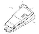
以下、本発明の実施の形態を図面を参照にして説明する。図2は、本発明の第1実施形態に係るテープ印刷装置1を正面側から示した外観斜視図である。図3は、第1実施形態に係るテープ印刷装置1を背面側から示した外観斜視図である。図2や図3に示すように、第1実施形態に係るテープ印刷装置1では、本体2に対して、複数のキーから構成されるキー操作部3や、ディスプレイ4、カッターレバー5等が設けられている。さらに、第1実施形態に係るテープ印刷装置1では、本体2に対して、カバー11が取り付けられている。
[1. Overview of First Embodiment]
Hereinafter, embodiments of the present invention will be described with reference to the drawings. FIG. 2 is an external perspective view showing thetape printer 1 according to the first embodiment of the present invention from the front side. FIG. 3 is an external perspective view showing thetape printer 1 according to the first embodiment from the back side. As shown in FIGS. 2 and 3, in thetape printer 1 according to the first embodiment, themain body 2 is provided with a key operation unit 3 including a plurality of keys, adisplay 4, acutter lever 5, and the like. It has been. Furthermore, in thetape printer 1 according to the first embodiment, acover 11 is attached to themain body 2.

図4は、カバー11の裏面を示した外観斜視図である。図4に示すように、カバー11には、突出部12や、一対の第1係爪部13A,13B、第2係爪部14等が設けられている。  FIG. 4 is an external perspective view showing the back surface of thecover 11. As shown in FIG. 4, thecover 11 is provided with aprotruding portion 12, a pair of first engaging claws 13 </ b> A and 13 </ b> B, a secondengaging pawl portion 14, and the like.

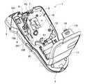
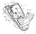
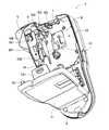
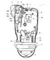
図5乃至図7は、第1実施形態に係るテープ印刷装置1を背面側から示した外観斜視図であって、カセット未装着時にカバー11が開けられた状態を示している。図8乃至図10は、第1実施形態に係るテープ印刷装置1を背面側から示した外観斜視図であって、カセット装着時にカバー11が開けられた状態を示している。  5 to 7 are external perspective views showing thetape printer 1 according to the first embodiment from the back side, and show a state in which thecover 11 is opened when the cassette is not attached. 8 to 10 are external perspective views showing thetape printer 1 according to the first embodiment from the back side, and show a state where thecover 11 is opened when the cassette is mounted.

カセット未装着時にカバー11が開けられた状態では、本体2に設けられたカセット装着部8が露呈する(図5乃至図7参照)。カセット装着部8には、装着内面10が形成されている。装着内面10には、一対の係着部K1,K2や、支持板41等が立設されている。  When thecover 11 is opened when the cassette is not mounted, thecassette mounting portion 8 provided in themain body 2 is exposed (see FIGS. 5 to 7). A mountinginner surface 10 is formed in thecassette mounting portion 8. On the mountinginner surface 10, a pair of engaging portions K1, K2, asupport plate 41, and the like are erected.

この点、カセット装着部8に入れられたカセットCに一対の係着部K1,K2が係合されると、カセットCをカセット装着部8内で正しくセッティングさせることができる(図8乃至図10参照)。このとき、カセットCの底壁CA1(下記図22等参照)が装着内面10に着接する。尚、カセットCの左右側壁には、一対の突条部V1,V2が設けられている。カセットCがカセット装着部8内に正しくセッティングされた際には、カセットCの一対の突条部V1,V2に対して、一対の係着部K1,K2がそれぞれ係合する。  In this regard, when the pair of engaging portions K1 and K2 are engaged with the cassette C placed in thecassette mounting portion 8, the cassette C can be set correctly in the cassette mounting portion 8 (FIGS. 8 to 10). reference). At this time, the bottom wall CA1 of the cassette C (see FIG. 22 and the like below) contacts the mountinginner surface 10. A pair of ridges V1 and V2 are provided on the left and right side walls of the cassette C. When the cassette C is correctly set in thecassette mounting portion 8, the pair of engaging portions K1, K2 engage with the pair of protrusions V1, V2 of the cassette C, respectively.

従って、例えば、後述する図31乃至図33に示すように、一対の係着部K1,K2に対してカセットCの一対の突条部V1,V2がそれぞれ載置された状態が放置されると、カセットCがカセット装着部8内に正しくセッティングされていない状態が保持される。  Therefore, for example, as shown in FIGS. 31 to 33 to be described later, when the pair of protrusions V1 and V2 of the cassette C are placed on the pair of engaging portions K1 and K2, respectively, is left unattended. The state in which the cassette C is not correctly set in thecassette mounting portion 8 is maintained.

支持板41には、サーマルヘッドH等が設けられている(図5,図7,図8,図10参照)。  Thesupport plate 41 is provided with a thermal head H or the like (see FIGS. 5, 7, 8, and 10).

本体2のカッターレバー5付近には、ローラホルダ101が設けられている。ローラホルダ101は、回動軸109によって、本体2に回動可能に支持される。さらに、ローラホルダ101は、不図示のコイルバネによって、カセット装着部8の内側から外側に向けて付勢される。ローラホルダ101の内部には、プラテンローラ102とテープ送りサブローラ103が軸支されている(図6,図7,図9,図10参照)。  Aroller holder 101 is provided near thecutter lever 5 of themain body 2. Theroller holder 101 is rotatably supported on themain body 2 by arotation shaft 109. Further, theroller holder 101 is urged from the inside to the outside of thecassette mounting portion 8 by a coil spring (not shown). Inside theroller holder 101, aplaten roller 102 and atape feed sub-roller 103 are pivotally supported (see FIGS. 6, 7, 9, and 10).

ローラホルダ101の外面には、押付面108が形成されている。また、押付面108が露出する挿脱口9が本体2に設けられている。挿脱口9には、本体2にカバー11が取り付けられた際に、カバー11の突出部12が差し込まれる。このとき、押付面108に突出部12が摺動し、ローラホルダ101が反付勢方向(カセット装着部8の外側から内側への方向)に回動するので、カセットCのテープ状フィルムを挟んで、プラテンローラ102がサーマルヘッドHに押し付けられる。尚、このような動作は、カセット装着部8にカセットCが未装着である時も同様であるが、この場合には、カセットCのテープ状フィルムが挟まれることなく、プラテンローラ102がサーマルヘッドHに直接に押し付けられる。  Apressing surface 108 is formed on the outer surface of theroller holder 101. Further, an insertion / removal opening 9 through which thepressing surface 108 is exposed is provided in themain body 2. When thecover 11 is attached to themain body 2, theprotruding portion 12 of thecover 11 is inserted into the insertion /removal port 9. At this time, the protrudingportion 12 slides on thepressing surface 108 and theroller holder 101 rotates in the counter-biasing direction (the direction from the outside to the inside of the cassette mounting portion 8), so that the tape-like film of the cassette C is sandwiched. Thus, theplaten roller 102 is pressed against the thermal head H. Such an operation is the same when the cassette C is not loaded in thecassette loading section 8, but in this case, theplaten roller 102 is moved by the thermal head without the tape-like film of the cassette C being sandwiched. Pressed directly against H.

図11乃至図13は、第1実施形態に係るテープ印刷装置1を背面側から示した外観斜視図である。さらに、図11乃至図13は、カセットCがカセット装着部8内に正しくセッティングされた際に、本体2にカバー11が取り付けられたことによって、カセットCのテープ状フィルムを挟んで、プラテンローラ102がサーマルヘッドHに押し付けられた状態を示している。尚、図11乃至図13では、プラテンローラ102がサーマルヘッドHに押し付けられた状態を明示するため、カセットCのテープ状フィルムやカバー11は記載されていない。  11 to 13 are external perspective views showing thetape printer 1 according to the first embodiment from the back side. Further, FIGS. 11 to 13 show that when the cassette C is correctly set in thecassette mounting portion 8, thecover 11 is attached to themain body 2, so that theplaten roller 102 is sandwiched by sandwiching the tape-like film of the cassette C. Shows a state in which it is pressed against the thermal head H. In FIGS. 11 to 13, in order to clearly show the state in which theplaten roller 102 is pressed against the thermal head H, the tape-like film and thecover 11 of the cassette C are not shown.

一方、本体2にカバー11が取り外された際には、カバー11の突出部12が挿脱口9から抜け離れる。このとき、押付面108から突出部12が離れ、ローラホルダ101が付勢方向(カセット装着部8の内側から外側への方向)に回動するので、プラテンローラ102がサーマルヘッドHから離間する(図8乃至図10参照)。  On the other hand, when thecover 11 is removed from themain body 2, the protrudingportion 12 of thecover 11 is detached from the insertion /removal port 9. At this time, the protrudingportion 12 is separated from thepressing surface 108 and theroller holder 101 is rotated in the urging direction (direction from the inside to the outside of the cassette mounting portion 8), so that theplaten roller 102 is separated from the thermal head H ( (See FIGS. 8 to 10).

カセット装着部8の周辺には、一対の第1係合口6A,6B(図11乃至図13参照)や第2係合口7が本体2に設けられている。各第1係合口6A,6Bは、本体2にカバー11が取り付けられる際に、カバー11の各第1係爪部13A,13Bがそれぞれ引っかけられる。第2係合口7は、本体2にカバー11が取り付けられた際に、カバー11の第2係爪部14と係り合う。よって、本体2にカバー11が取り付けられた際には、第2係爪部14の近傍にある凸状の押下部141をユーザが押下すれば、第2係爪部14と第2係合口7の係り合いが外れて、本体2からカバー11を取り外すことが可能となる。  A pair offirst engagement ports 6 A and 6 B (see FIGS. 11 to 13) and asecond engagement port 7 are provided in themain body 2 around thecassette mounting portion 8. When thecover 11 is attached to themain body 2, the firstengaging claws 13A and 13B of thecover 11 are hooked on the first engagingports 6A and 6B, respectively. Thesecond engagement port 7 engages with the secondengagement claw portion 14 of thecover 11 when thecover 11 is attached to themain body 2. Therefore, when thecover 11 is attached to themain body 2, if the user presses the convexpressing portion 141 in the vicinity of the secondengaging claw portion 14, the secondengaging claw portion 14 and the secondengaging port 7 are pressed. And thecover 11 can be removed from themain body 2.

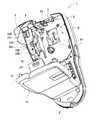
ところで、カセット装着部8にカセットCが未装着である場合には、本体2にカバー11が取り付けられると、上述したように、プラテンローラ102がサーマルヘッドHに直接に押し付けられる。この状態が、高温下で長期間放置されると、図14乃至図16に示すように、プラテンローラ102がサーマルヘッドHに固着する場合がある。図14乃至図16は、第1実施形態に係るテープ印刷装置1を背面側から示した外観斜視図であって、カセット装着部8にカセットCが未装着である場合に、カバー11が開けられ、サーマルヘッドHに固着したプラテンローラ102が露呈した状態を示している。  By the way, when the cassette C is not attached to thecassette attaching portion 8, when thecover 11 is attached to themain body 2, theplaten roller 102 is directly pressed against the thermal head H as described above. If this state is left for a long time at a high temperature, theplaten roller 102 may adhere to the thermal head H as shown in FIGS. 14 to 16 are external perspective views showing thetape printer 1 according to the first embodiment from the back side, and thecover 11 is opened when the cassette C is not attached to thecassette attachment portion 8. Theplaten roller 102 fixed to the thermal head H is exposed.

このように、サーマルヘッドHに固着したプラテンローラ102が露呈した状態にある場合には、図17乃至図19に示すようにして、カセットCをカセット装着部8内に装着しようとすれば、カセットCのテープ状フィルムTFがプラテンローラ102等に突き当たってしまう。図17乃至図19は、第1実施形態に係るテープ印刷装置1を背面側から示した外観斜視図であって、カバー11が取り外され、サーマルヘッドHにプラテンローラ102が固着した状態の下で、カセットCがカセット装着部8内に装着されようとするときの様子を示した図である。  Thus, when theplaten roller 102 fixed to the thermal head H is in an exposed state, as shown in FIGS. 17 to 19, if the cassette C is to be mounted in thecassette mounting portion 8, the cassette C tape-shaped film TF hits theplaten roller 102 or the like. 17 to 19 are external perspective views showing thetape printer 1 according to the first embodiment from the back side, with thecover 11 removed and theplaten roller 102 fixed to the thermal head H. FIG. 10 is a view showing a state where the cassette C is about to be mounted in thecassette mounting portion 8.

〔2.突起部の概要〕
そこで、第1実施形態に係るテープ印刷装置1では、図5乃至図17、図19に示すように、カセット装着部8に向けて突き出た突起部201を、ローラホルダ101に設けている。また、突起部201においては、本体2に取り付けられたカバー11と向かい合う面を、付根から先端に渡って下る傾斜面にしている。
[2. (Outline of protrusion)
Therefore, in thetape printer 1 according to the first embodiment, as shown in FIGS. 5 to 17 and 19, theroller holder 101 is provided with a protrudingportion 201 protruding toward thecassette mounting portion 8. Moreover, in theprotrusion part 201, the surface which faces thecover 11 attached to themain body 2 is made into the inclined surface which goes down from a root to a front-end | tip.

〔3.突起部とカセットの位置関係〕
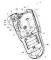
図20乃至図22は、第1実施形態に係るテープ印刷装置1のサーマルヘッドHにプラテンローラ102が固着した状態にある場合において、ユーザがカセットCをカセット装着部8内に装着させようとするときの、ローラホルダ101の突起部201とカセットCの位置関係を示した図である。図20は平面図である。図21は、図20の矢視Aから見た側面図である。図22は、図20の矢視Bから見た側面図である。
[3. (Positional relationship between protrusion and cassette)
20 to 22 show that when theplaten roller 102 is fixed to the thermal head H of thetape printer 1 according to the first embodiment, the user tries to mount the cassette C in thecassette mounting portion 8. It is the figure which showed the positional relationship of theprojection part 201 of theroller holder 101, and the cassette C at the time. FIG. 20 is a plan view. FIG. 21 is a side view as seen from the direction of arrow A in FIG. FIG. 22 is a side view seen from the arrow B of FIG.

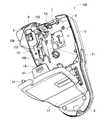
図1、図23と図24は、第1実施形態に係るテープ印刷装置1のサーマルヘッドHにプラテンローラ102が固着した状態にある場合において、ユーザがカセットCをカセット装着部8内に装着させようとするときに、カセットCがローラホルダ101の突起部201に当接する関係を示した図である。図1は平面図である。図23は、図1の矢視Aから見た側面図である。図24は、図1の矢視Bから見た側面図である。  1, 23, and 24 show that the user mounts the cassette C in thecassette mounting portion 8 when theplaten roller 102 is fixed to the thermal head H of thetape printer 1 according to the first embodiment. FIG. 6 is a diagram showing a relationship in which the cassette C abuts on theprotrusion 201 of theroller holder 101 when trying to do so. FIG. 1 is a plan view. 23 is a side view as seen from the direction of arrow A in FIG. 24 is a side view as seen from the direction of arrow B in FIG.

図25乃至図27は、第1実施形態に係るテープ印刷装置1のカセット装着部8内にカセットCが正しくセッティングされたときの、ローラホルダ101の突起部201とカセットCの位置関係を示した図である。図25は平面図である。図26は、図25の矢視Aから見た側面図である。図27は、図25の矢視Bから見た側面図である。  25 to 27 show the positional relationship between the protrudingportion 201 of theroller holder 101 and the cassette C when the cassette C is correctly set in thecassette mounting portion 8 of thetape printer 1 according to the first embodiment. FIG. FIG. 25 is a plan view. FIG. 26 is a side view as seen from the direction of arrow A in FIG. 27 is a side view as seen from the direction of arrow B in FIG.

図28乃至図30は、第1実施形態に係るテープ印刷装置1のカセット装着部8内にカセットCが正しくセッティングされた後で、ローラホルダ101を支持板41に押し付けたときの、ローラホルダ101の突起部201とカセットCの位置関係を示した図である。図28は平面図である。図29は、図28の矢視Aから見た側面図である。図30は、図28の矢視Bから見た側面図である。  28 to 30 show theroller holder 101 when theroller holder 101 is pressed against thesupport plate 41 after the cassette C is correctly set in thecassette mounting portion 8 of thetape printer 1 according to the first embodiment. It is the figure which showed the positional relationship of theprojection part 201 and cassette C of FIG. FIG. 28 is a plan view. 29 is a side view as seen from the direction of arrow A in FIG. FIG. 30 is a side view seen from the arrow B of FIG.

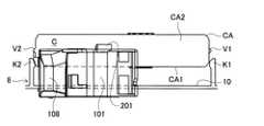
尚、カセットCは、カセット装着部8内に正しくセッティングされたときに、カセット装着部8の装着内面10に対向する底壁CA1や、その底壁CA1に連続しローラホルダ101に対向する正面側壁CA2等で構成されるカセットケースCAを有する。また、図20乃至図30では、カセットCのテープ状フィルムTFは記載されていない。  When the cassette C is correctly set in thecassette mounting portion 8, the bottom wall CA1 that faces the mountinginner surface 10 of thecassette mounting portion 8 and the front side wall that continues to the bottom wall CA1 and faces theroller holder 101 are provided. It has a cassette case CA composed of CA2 or the like. 20 to 30, the tape-shaped film TF of the cassette C is not described.

第1実施形態に係るテープ印刷装置1では、サーマルヘッドHにプラテンローラ102が固着した状態にある場合に、ユーザがカセットCをカセット装着部8内に装着しようとすれば(図17乃至図19参照)、ローラホルダ101の突起部201とカセットCの位置関係は、図20乃至図22に示すようになる。  In thetape printer 1 according to the first embodiment, when theplaten roller 102 is fixed to the thermal head H, the user tries to mount the cassette C in the cassette mounting portion 8 (FIGS. 17 to 19). Reference), the positional relationship between theprotrusion 201 of theroller holder 101 and the cassette C is as shown in FIGS.

そして、ユーザがカセットCをカセット装着部8内に正しくセッティングしようとすれば、カセットCの底壁CA1や正面側壁CA2がローラホルダ101の突起部201に当接する。このとき、カセットCは、ユーザによってカセット装着部8に向かって移動させられている。従って、図1、図23と図24に示すように、カセットCの底壁CA1や正面側壁CA2がローラホルダ101の突起部201に当接している間は、カセットCがローラホルダ101の突起部201を押動する。これにより、ローラホルダ101には、回動軸109を中心として図1における図面上の反時計回りに回転させる力が作用し、サーマルヘッドHからプラテンローラ102が引き剥がされるので、ローラホルダ101が付勢方向(カセット装着部8の内側から外側への方向)に回動する。  If the user attempts to set the cassette C correctly in thecassette mounting portion 8, the bottom wall CA <b> 1 and the front side wall CA <b> 2 of the cassette C abut against theprotrusion 201 of theroller holder 101. At this time, the cassette C is moved toward thecassette mounting portion 8 by the user. Accordingly, as shown in FIGS. 1, 23, and 24, while the bottom wall CA <b> 1 and the front side wall CA <b> 2 of the cassette C are in contact with the protrudingportion 201 of theroller holder 101, the cassette C is protruding from theroller holder 101. 201 is pushed. As a result, a force that rotates counterclockwise on the drawing in FIG. 1 acts on theroller holder 101 around therotation shaft 109, and theplaten roller 102 is peeled off from the thermal head H. It rotates in the urging direction (direction from the inside to the outside of the cassette mounting portion 8).

その後、ローラホルダ101の付勢方向(カセット装着部8の内側から外側への方向)への回動が停止すると、図25乃至図27に示すように、ローラホルダ101が支持板41から離れた状態が維持されるので、カセット装着部8内にカセットCを正しくセッティングさせることができる。  Thereafter, when the rotation of theroller holder 101 in the urging direction (the direction from the inside to the outside of the cassette mounting portion 8) stops, theroller holder 101 moves away from thesupport plate 41 as shown in FIGS. Since the state is maintained, the cassette C can be correctly set in thecassette mounting portion 8.

カセット装着部8内にカセットCが正しくセッティングされた後は、上述したように、本体2にカバー11を取り付けると、ローラホルダ101が反付勢方向(カセット装着部8の外側から内側への方向)に回動する。このとき、ローラホルダ101の突起部201は、カセットCのカセットケースCA上(でカバー11下)を移動する。従って、ローラホルダ101の突起部201に妨げられることなく、図28乃至図30に示すようにして、ローラホルダ101が支持板41に押し付けられる。  After the cassette C is correctly set in thecassette mounting portion 8, as described above, when thecover 11 is attached to themain body 2, theroller holder 101 moves in the counter-biasing direction (the direction from the outside to the inside of thecassette mounting portion 8. ). At this time, theprotrusion 201 of theroller holder 101 moves on the cassette case CA of the cassette C (below the cover 11). Therefore, theroller holder 101 is pressed against thesupport plate 41 as shown in FIGS. 28 to 30 without being obstructed by theprotrusion 201 of theroller holder 101.

その一方で、カセット装着部8内にカセットCが正しくセッティングされていない場合には、本体2にカバー11を取り付けて、ローラホルダ101が反付勢方向(カセット装着部8の外側から内側への方向)に回動させようとすれば、図31乃至図33に示すように、ローラホルダ101の突起部201がカセットCの正面側壁CAに当接するので、ローラホルダ101を支持板41に押し付けることはできない。  On the other hand, when the cassette C is not set correctly in thecassette mounting portion 8, thecover 11 is attached to themain body 2, and theroller holder 101 moves in the counter-biasing direction (from the outside of thecassette mounting portion 8 to the inside). 31 to 33, theprotrusion 201 of theroller holder 101 comes into contact with the front side wall CA of the cassette C, so that theroller holder 101 is pressed against thesupport plate 41 as shown in FIGS. I can't.

尚、図31乃至図33は、第1実施形態に係るテープ印刷装置1のカセット装着部8内にカセットCが正しくセッティングされていない状態で、ローラホルダ101を支持板41に押し付けようとしたときのローラホルダ101の突起部201とカセットCの位置関係を示した図である。図31は平面図である。図32は、図31の矢視Aから見た側面図である。図33は、図31の矢視Bから見た側面図である。  31 to 33 show a case where theroller holder 101 is pressed against thesupport plate 41 in a state where the cassette C is not set correctly in thecassette mounting portion 8 of thetape printer 1 according to the first embodiment. FIG. 6 is a view showing the positional relationship between theprotrusion 201 of theroller holder 101 and the cassette C. FIG. 31 is a plan view. FIG. 32 is a side view as seen from the direction of arrow A in FIG. FIG. 33 is a side view as seen from the direction of arrow B in FIG.

〔4.まとめ〕
以上詳細に説明したように、第1実施形態では、突起部201を、テープ印刷装置1のローラホルダ101に設けている。従って、ローラホルダ101が支持板41に押し付けられ、サーマルヘッドHにプラテンローラ102が密着した状態にあると、カセット装着部8内にカセットCが装着される過程において(例えば、図1や、図17乃至図27参照)、突起部201を介して、カセットCがローラホルダ101を押すので、ローラホルダ101が付勢方向(カセット装着部8の内側から外側への方向)に移動し、ローラホルダ101が支持板41から離隔する。よって、サーマルヘッドHにプラテンローラ102が固着し、ローラホルダ101が支持板41に押し付けられた状態が維持されていても、カセットCの装着によって、ローラホルダ101を支持板41から引き離すことが可能である。
[4. (Summary)
As described above in detail, in the first embodiment, theprotrusion 201 is provided on theroller holder 101 of thetape printer 1. Accordingly, when theroller holder 101 is pressed against thesupport plate 41 and theplaten roller 102 is in close contact with the thermal head H, the cassette C is mounted in the cassette mounting portion 8 (for example, FIG. 17 to 27), since the cassette C pushes theroller holder 101 through theprotrusion 201, theroller holder 101 moves in the urging direction (direction from the inside of thecassette mounting portion 8 to the outside), and theroller holder 101 is separated from thesupport plate 41. Therefore, even when theplaten roller 102 is fixed to the thermal head H and the state in which theroller holder 101 is pressed against thesupport plate 41 is maintained, theroller holder 101 can be separated from thesupport plate 41 by mounting the cassette C. It is.

この点、突起部201は、本体2に取り付けられたカバー11と向かい合う面が、付根から先端に渡って下っていく傾斜面になっている。よって、カセット装着部8内にカセットCが装着される過程において(例えば、図1や、図17乃至図27参照)、突起部201の斜面がカセットCの底壁CA1や正面側壁CA2に当接する。従って、サーマルヘッドHにプラテンローラ102が固着することにより、支持板41に押し付けられた状態が維持されているローラホルダ101に対して、付勢方向(カセット装着部8の内側から外側への方向)へ押す力をカセットCから効率的に作用させることができる。  In this respect, theprotrusion 201 has an inclined surface that faces thecover 11 attached to themain body 2 and descends from the root to the tip. Therefore, in the process in which the cassette C is mounted in the cassette mounting portion 8 (see, for example, FIG. 1 and FIGS. 17 to 27), the inclined surface of the protrudingportion 201 contacts the bottom wall CA1 and the front side wall CA2 of the cassette C. . Therefore, when theplaten roller 102 is fixed to the thermal head H, the urging direction (the direction from the inside to the outside of the cassette mounting portion 8) is applied to theroller holder 101 that is kept pressed against the support plate 41. ) Can be efficiently applied from the cassette C.

その一方で、テープ印刷装置1のカセット装着部8内のカセットCが正しくセッティングされていない状態にある場合には、本体2にカバー11が取り付けられることによって、ローラホルダ101が反付勢方向(カセット装着部8の外側から内側への方向)に回動させられると、反付勢方向(カセット装着部8の外側から内側への方向)に回動させられたローラホルダ101が、図31乃至図33に示すように、その突起部201を介して、カセットCの正面側壁CAに当接する。従って、ローラホルダ101の反付勢方向(カセット装着部8の外側から内側への方向)への回動が途中で制止され、ローラホルダ101を支持板41に押し付けることができない。よって、この状態でテープ印刷が開始されても、カセット装着部8内でカセットCのテープ状フィルムTFがジャムを起こすことはない。  On the other hand, when the cassette C in thecassette mounting portion 8 of thetape printer 1 is not set correctly, theroller holder 101 is moved in the counter-biasing direction ( When thecassette mounting portion 8 is rotated in the direction from the outside to the inside, theroller holder 101 rotated in the counter-biasing direction (the direction from the outside to the inside of the cassette mounting portion 8) is shown in FIG. As shown in FIG. 33, it comes into contact with the front side wall CA of the cassette C through theprotrusion 201. Accordingly, the rotation of theroller holder 101 in the counter-bias direction (the direction from the outside to the inside of the cassette mounting portion 8) is stopped midway, and theroller holder 101 cannot be pressed against thesupport plate 41. Therefore, even if the tape printing is started in this state, the tape-like film TF of the cassette C does not jam in thecassette mounting portion 8.

尚、カセット装着部8内にカセットCが正しくセッティングされている場合に、図11乃至図13や、図28乃至図30に示すように、サーマルヘッドHにプラテンローラ102が密着した状態にあるときは、ローラホルダ101の突起部201が、カセットCのカセットケースCA上(且つカバー11下)で突き出た状態になる。さらに、図示するように、カセット装着部8とカセットCがほぼ同じ大きさであることを考慮すれば、サーマルヘッドHにプラテンローラ102が密着した状態にあるときのローラホルダ101の突起部201は、カセット装着部8にカセットCが装着される際の装着軌跡内に突出している。よって、カセットCは、支持板41に押し付けられた状態にあるローラホルダ101の突起部201、すなわち、サーマルヘッドHに固着したプラテンローラ102を軸支するローラホルダ101と当接することなくして、カセット装着部8内にカセットCが装着されることはない。  When the cassette C is correctly set in thecassette mounting portion 8, when theplaten roller 102 is in close contact with the thermal head H as shown in FIGS. 11 to 13 and FIGS. 28 to 30. Theprotrusion 201 of theroller holder 101 protrudes on the cassette case CA (and below the cover 11) of the cassette C. Further, as shown in the drawing, when considering that thecassette mounting portion 8 and the cassette C are approximately the same size, theprotrusion 201 of theroller holder 101 when theplaten roller 102 is in close contact with the thermal head H is Thecassette mounting portion 8 protrudes into the mounting locus when the cassette C is mounted. Therefore, the cassette C is not brought into contact with theprotrusion 201 of theroller holder 101 that is pressed against thesupport plate 41, that is, theroller holder 101 that pivotally supports theplaten roller 102 fixed to the thermal head H. The cassette C is not mounted in the mountingportion 8.

また、第1実施形態では、突起部201を、テープ印刷装置1のローラホルダ101に設けているが、テープ印刷装置1の印刷に支障がない。なぜなら、ローラホルダ101は、テープ印刷装置1のカセット装着部8内にカセットCが正しくセッティングされたときには、図11乃至図13や、図28乃至図30に示すように、カセットCに突起部202を介して干渉することがないので、反付勢方向(カセット装着部8の外側から内側への方向)に回動して、支持板41に押し付けられることが可能だからである。従って、カセットCが通常使用される印字用のものであっても、ローラホルダ101を支持板41から引き離すことが可能である。  In the first embodiment, theprotrusion 201 is provided on theroller holder 101 of thetape printer 1, but there is no problem in printing of thetape printer 1. This is because when the cassette C is correctly set in thecassette mounting portion 8 of thetape printer 1, theroller holder 101 has a protrudingportion 202 on the cassette C as shown in FIGS. 11 to 13 and FIGS. This is because it can rotate in the counter-biasing direction (the direction from the outside to the inside of the cassette mounting portion 8) and be pressed against thesupport plate 41. Accordingly, theroller holder 101 can be pulled away from thesupport plate 41 even when the cassette C is for printing that is normally used.

また、第1実施形態に係るテープ印刷装置1は、カセット装着部8に設けられた一対の係着部K1,K2を備えている。そして、カセット装着部8内のカセットCが一対の係着部K1,K2に係合されると、図8乃至図13や図25乃至図30に示すように、カセット装着部8内のカセットCが、正しくセッティングされた状態で固定される。  Thetape printer 1 according to the first embodiment includes a pair of engaging portions K1 and K2 provided in thecassette mounting portion 8. When the cassette C in thecassette mounting portion 8 is engaged with the pair of engaging portions K1 and K2, as shown in FIGS. 8 to 13 and FIGS. 25 to 30, the cassette C in thecassette mounting portion 8 is used. Is fixed in the correct setting.

従って、カセット装着部8にカセットCが入れられた際に、ユーザ等がそのカセットCを一対の係着部K1,K2に係合させれば、常に、そのカセットCはカセット装着部8に正しくセッティングさせた状態に固定される。しかしながら、このような機構では、一対の係着部K1,K2に対してカセットCの一対の突条部V1,V2が載置されるような状態を必ず経由しなければならない。このような状態、すなわち、例えば、図31乃至図33に示すように、そのカセットCが一対の係着部K1,K2に係合されない状態が放置されると、かえって、そのカセットCはカセット装着部8に正しくセッティングされていない状態に保持される。これにより、カセットC内のテープ状フィルムTFのジャムが発生しやすい環境が作り出されてしまうので、第1実施形態の動作を行う機構を備える必要性が高くなる。  Therefore, when the cassette C is inserted into thecassette mounting portion 8, if the user or the like engages the cassette C with the pair of engaging portions K1 and K2, the cassette C is always correctly attached to thecassette mounting portion 8. Fixed to the set state. However, in such a mechanism, a state in which the pair of protrusions V1, V2 of the cassette C is placed on the pair of engaging portions K1, K2 must be passed. If, for example, as shown in FIGS. 31 to 33, the cassette C is not engaged with the pair of engaging portions K1 and K2, the cassette C is mounted on the cassette. Thepart 8 is held in a state where it is not set correctly. As a result, an environment in which jamming of the tape-shaped film TF in the cassette C is likely to occur is created, and thus the necessity of providing a mechanism for performing the operation of the first embodiment is increased.

また、第1実施形態に係るテープ印刷装置1では、カバー11は本体2に対し着脱可能であるので、カセット装着部8が開放される際には、カバー11が本体2から取り外される。従って、カバー11を自由に動かすことができるので、カバー11が本体2に取り付けられることによって、カセット装着部8がカバー11で掩覆される際には、カセット装着部8に入れられたカセットCが正しくセッティングされていない状態にあっても、カバー11が本体2に強引に取り付けられてしまうことがある。これにより、カセットC内のテープ状フィルムTFのジャムが発生しやすい環境が作り出されてしまうので、第1実施形態の動作を行う機構を備える必要性が高くなる。  Further, in thetape printer 1 according to the first embodiment, thecover 11 is detachable from themain body 2, so that thecover 11 is removed from themain body 2 when thecassette mounting portion 8 is opened. Accordingly, thecover 11 can be freely moved. Therefore, when thecassette mounting portion 8 is covered with thecover 11 by attaching thecover 11 to themain body 2, the cassette C placed in thecassette mounting portion 8 is used. Even if thecover 11 is not set correctly, thecover 11 may be forcibly attached to themain body 2. As a result, an environment in which jamming of the tape-shaped film TF in the cassette C is likely to occur is created, and thus the necessity of providing a mechanism for performing the operation of the first embodiment is increased.

〔5.第2実施形態〕
第1実施形態では、突起部201を、テープ印刷装置1のローラホルダ101に設けている。しかしながら、以下に説明する第2実施形態のように、突起部201に相当するものをカセットC側に設けてもよい。
[5. Second Embodiment]
In the first embodiment, theprotrusion 201 is provided on theroller holder 101 of thetape printer 1. However, as in the second embodiment described below, a portion corresponding to theprotrusion 201 may be provided on the cassette C side.

図34乃至図36は、第2実施形態においてテープ印刷装置100を背面側から示した外観斜視図であって、カセット未装着時にカバー11が開けられた状態を示している。図37乃至図39は、第2実施形態においてテープ印刷装置100を背面側から示した外観斜視図であって、カセット装着時にカバー11が開けられた状態を示している。  34 to 36 are external perspective views showing thetape printer 100 from the back side in the second embodiment, and show a state in which thecover 11 is opened when the cassette is not attached. FIGS. 37 to 39 are external perspective views showing thetape printer 100 from the back side in the second embodiment, and show a state where thecover 11 is opened when the cassette is mounted.

図40乃至図42は、第2実施形態においてテープ印刷装置100を背面側から示した外観斜視図である。さらに、図40乃至図42は、カセットCがカセット装着部8内に正しくセッティングされた際に本体2にカバー11が取り付けられたことによって、カセットCのテープ状フィルムを挟んで、プラテンローラ102がサーマルヘッドHに押し付けられた状態を示している。尚、図40乃至図42では、プラテンローラ102がサーマルヘッドHに押し付けられた状態を明示するため、カセットCのテープ状フィルムやカバー11は記載されていない。  40 to 42 are external perspective views showing thetape printer 100 from the back side in the second embodiment. 40 to 42 show that when the cassette C is correctly set in thecassette mounting portion 8, thecover 11 is attached to themain body 2, so that theplaten roller 102 is sandwiched between the tape-like films of the cassette C. A state of being pressed against the thermal head H is shown. In FIGS. 40 to 42, the tape-like film and thecover 11 of the cassette C are not shown in order to clearly show the state where theplaten roller 102 is pressed against the thermal head H.

図43乃至図45は、第2実施形態においてテープ印刷装置100を背面側から示した外観斜視図であって、カセット装着部8にカセットCが未装着である場合に、カバー11が開けられ、サーマルヘッドHに固着したプラテンローラ102が露呈した状態を示している。  43 to 45 are external perspective views showing thetape printer 100 from the back side in the second embodiment, and when the cassette C is not attached to thecassette attachment portion 8, thecover 11 is opened, The state where theplaten roller 102 fixed to the thermal head H is exposed is shown.

図46乃至図48は、第2実施形態においてテープ印刷装置100を背面側から示した外観斜視図であって、カバー11が取り外され、サーマルヘッドHにプラテンローラ102が固着した状態の下で、カセットCがカセット装着部8内に装着されようとするときの様子を示した図である。  46 to 48 are external perspective views showing thetape printing apparatus 100 from the back side in the second embodiment, with thecover 11 removed and theplaten roller 102 fixed to the thermal head H. It is the figure which showed a mode when cassette C is going to be mounted in thecassette mounting part 8. FIG.

図34乃至図48に示すテープ印刷装置100は、第1実施形態に係るテープ印刷装置1とは異なって、第1実施形態にはあった突起部201がローラホルダ101には設けられていない。その他は、第1実施形態に係るテープ印刷装置1と同じなので、第1実施形態と同じ符号を付し、テープ印刷装置100についての詳細な説明は省略する。  Thetape printing apparatus 100 shown in FIGS. 34 to 48 is different from thetape printing apparatus 1 according to the first embodiment in that theroller holder 101 is not provided with theprotrusion 201 that was in the first embodiment. Others are the same as those of thetape printer 1 according to the first embodiment, and therefore, the same reference numerals as those of the first embodiment are given, and detailed description of thetape printer 100 is omitted.

これに対し、カセットCには、カセットケースCAの底壁CA1と正面側壁CA2との接続部分に、カセット装着部8内に正しくセッティングされた際にローラホルダ101に向けて突き出た突起部202を設けている。また、突起部202においては、カセットCがカセット装着部8内に正しくセッティングされた際には、底壁CA1に向かうほどローラホルダ101から離れていく傾斜面を有する。この突起部202は、第1実施形態の突起部201と同様な機能を有する。  On the other hand, the cassette C has a protrudingportion 202 that protrudes toward theroller holder 101 when correctly set in thecassette mounting portion 8 at the connection portion between the bottom wall CA1 and the front side wall CA2 of the cassette case CA. Provided. Further, the protrudingportion 202 has an inclined surface that moves away from theroller holder 101 toward the bottom wall CA1 when the cassette C is correctly set in thecassette mounting portion 8. Theprotrusion 202 has a function similar to that of theprotrusion 201 of the first embodiment.

すなわち、第2実施形態では、突起部202を、カセットCに設けている。従って、ローラホルダ101が支持板41に押し付けられ、サーマルヘッドHにプラテンローラ102が密着した状態にあると、カセット装着部8内にカセットCが装着される過程において(例えば、図34乃至図40参照)、突起部202を介して、カセットCがローラホルダ101を押すので、ローラホルダ101が付勢方向(カセット装着部8の内側から外側への方向)に移動し、支持板41から離隔する。よって、サーマルヘッドHにプラテンローラ102が固着し、ローラホルダ101が支持板41に押し付けられた状態が維持されていても、カセットCの装着によって、ローラホルダ101を支持板41から引き離すことが可能である。  That is, in the second embodiment, the protrudingportion 202 is provided in the cassette C. Accordingly, when theroller holder 101 is pressed against thesupport plate 41 and theplaten roller 102 is in close contact with the thermal head H, the cassette C is mounted in the cassette mounting portion 8 (for example, FIGS. 34 to 40). Since the cassette C pushes theroller holder 101 through theprotrusion 202, theroller holder 101 moves in the urging direction (the direction from the inside to the outside of the cassette mounting portion 8) and is separated from thesupport plate 41. . Therefore, even when theplaten roller 102 is fixed to the thermal head H and the state in which theroller holder 101 is pressed against thesupport plate 41 is maintained, theroller holder 101 can be separated from thesupport plate 41 by mounting the cassette C. It is.

この点、突起部202は、カセットCがカセット装着部8内に正しくセッティングされた際には、底壁CA1に向かうほどローラホルダ101から離れていく傾斜面を有する。よって、カセット装着部8内にカセットCが装着される過程では(例えば、図34乃至図40参照)、突起部202の斜面が、ローラホルダ101に当接する。従って、サーマルヘッドHにプラテンローラ102が固着し、支持板41に押し付けられた状態が維持されているローラホルダ101に対し、付勢方向(カセット装着部8の内側から外側への方向)へ押す力をカセットCから効率的に作用させることができる。  In this regard, the protrudingportion 202 has an inclined surface that moves away from theroller holder 101 toward the bottom wall CA1 when the cassette C is correctly set in thecassette mounting portion 8. Therefore, in the process in which the cassette C is mounted in the cassette mounting portion 8 (see, for example, FIG. 34 to FIG. 40), the inclined surface of theprotrusion 202 contacts theroller holder 101. Accordingly, theplaten roller 102 is fixed to the thermal head H, and is pressed in the urging direction (the direction from the inside to the outside of the cassette mounting portion 8) against theroller holder 101 that is kept pressed against thesupport plate 41. The force can be efficiently applied from the cassette C.

その一方で、テープ印刷装置100のカセット装着部8内のカセットCが正しくセッティングされていない状態にある場合には、本体2にカバー11を取り付けられることによって、ローラホルダ101が反付勢方向(カセット装着部8の外側から内側への方向)に回動させられると、反付勢方向(カセット装着部8の外側から内側への方向)に回動させられたローラホルダ101が、カセットCの突起部202に当接する。従って、ローラホルダ101の反付勢方向(カセット装着部8の外側から内側への方向)への回動が途中で制止され、ローラホルダ101を支持板41に押し付けることができない。よって、この状態でテープ印刷が開始されても、カセット装着部8内でカセットCのテープ状フィルムTFがジャムを起こすことはない。  On the other hand, when the cassette C in thecassette mounting portion 8 of thetape printer 100 is not set correctly, theroller holder 101 is moved in the counter-biasing direction ( When thecassette holder 8 is rotated in the direction from the outside to the inside, theroller holder 101 rotated in the counter-biasing direction (the direction from the outside to the inside of the cassette holder 8) is Abuts against theprotrusion 202. Accordingly, the rotation of theroller holder 101 in the counter-bias direction (the direction from the outside to the inside of the cassette mounting portion 8) is stopped midway, and theroller holder 101 cannot be pressed against thesupport plate 41. Therefore, even if the tape printing is started in this state, the tape-like film TF of the cassette C does not jam in thecassette mounting portion 8.

尚、カセット装着部8内にカセットCが正しくセッティングされている場合に、図40乃至図42に示すように、サーマルヘッドHにプラテンローラ102が密着した状態にあるときは、カセットCに設けられた突起部202が、ローラホルダ101の内側に突き出た状態になる。さらに、図示するように、カセット装着部8とカセットCがほぼ同じ大きさであることを考慮すれば、サーマルヘッドHにプラテンローラ102が密着した状態にあるときのローラホルダ101は、カセット装着部8にカセットCが装着される際の突起部202の軌跡内に突出している。よって、カセットCは、その突起部202が、支持板41に押し付けられた状態にあるローラホルダ101と当接することなくして、カセット装着部8内にカセットCが装着されることはない。  When the cassette C is correctly set in thecassette mounting portion 8, when theplaten roller 102 is in close contact with the thermal head H as shown in FIGS. The protrudingportion 202 protrudes inside theroller holder 101. Further, as shown in the drawing, considering that thecassette mounting portion 8 and the cassette C are approximately the same size, theroller holder 101 when theplaten roller 102 is in close contact with the thermal head H is the cassette mounting portion. 8 protrudes into the locus of theprotrusion 202 when the cassette C is mounted. Therefore, the cassette C is not mounted in thecassette mounting portion 8 without theprotrusion 202 of the cassette C coming into contact with theroller holder 101 pressed against thesupport plate 41.

また、第2実施形態では、突起部202を、カセットCに設けているが、テープ印刷装置100の印刷に支障がない。なぜなら、ローラホルダ101は、テープ印刷装置100のカセット装着部8内にカセットCが正しくセッティングされたときには、図40乃至図42に示すように、カセットCに突起部202を介して干渉することがないので、反付勢方向(カセット装着部8の外側から内側への方向)に移動して支持板41に押し付けられることが可能だからある。従って、カセットCが通常使用される印字用のものであっても、ローラホルダ101を支持板41から引き離すことが可能である。  In the second embodiment, theprotrusion 202 is provided in the cassette C, but there is no problem in printing with thetape printer 100. This is because theroller holder 101 may interfere with the cassette C through theprojection 202 as shown in FIGS. 40 to 42 when the cassette C is correctly set in thecassette mounting portion 8 of thetape printer 100. This is because it can move in the counter-biasing direction (the direction from the outside to the inside of the cassette mounting portion 8) and be pressed against thesupport plate 41. Accordingly, theroller holder 101 can be pulled away from thesupport plate 41 even when the cassette C is for printing that is normally used.

また、第2実施形態において、テープ印刷装置100は、カセット装着部8に設けられた一対の係着部K1,K2を備えている。そして、カセット装着部8内のカセットCが一対の係着部K1,K2に係合されると、図37乃至図42に示すように、カセット装着部8内のカセットCが、正しくセッティングされた状態で固定される。  In the second embodiment, thetape printer 100 includes a pair of engaging portions K1 and K2 provided in thecassette mounting portion 8. Then, when the cassette C in thecassette mounting portion 8 is engaged with the pair of engaging portions K1 and K2, the cassette C in thecassette mounting portion 8 is correctly set as shown in FIGS. Fixed in state.

従って、カセット装着部8にカセットCが入れられた際に、ユーザ等がそのカセットCを一対の係着部K1,K2に係合させれば、常に、そのカセットCはカセット装着部8に正しくセッティングさせた状態に固定される。しかしながら、このような機構では、一対の係着部K1,K2に対してカセットCの一対の突条部V1,V2が載置されるような状態を必ず経由しなければならない。このような状態、すなわち、例えば、そのカセットCが一対の係着部K1,K2に係合されない状態が放置されると、かえって、そのカセットCはカセット装着部8に正しくセッティングされていない状態に保持される。これにより、カセットC内のテープ状フィルムTFのジャムが発生しやすい環境が作り出されてしまうので、第2実施形態の動作を行う機構を備える必要性が高くなる。  Therefore, when the cassette C is inserted into thecassette mounting portion 8, if the user or the like engages the cassette C with the pair of engaging portions K1 and K2, the cassette C is always correctly attached to thecassette mounting portion 8. Fixed to the set state. However, in such a mechanism, a state in which the pair of protrusions V1, V2 of the cassette C is placed on the pair of engaging portions K1, K2 must be passed. In such a state, for example, when the cassette C is not engaged with the pair of engaging portions K1 and K2, the cassette C is not properly set in thecassette mounting portion 8. Retained. As a result, an environment in which jamming of the tape-shaped film TF in the cassette C is likely to occur is created, and thus the necessity of providing a mechanism for performing the operation of the second embodiment is increased.

また、第2実施形態において、テープ印刷装置100では、カバー11は本体2に対し着脱可能であるので、カセット装着部8が開放される際には、カバー11が本体2から取り外される。従って、カバー11を自由に動かすことができるので、カバー11が本体2に取り付けられることによって、カセット装着部8がカバー11で掩覆される際には、カセット装着部8に入れられたカセットCが正しくセッティングされていない状態にあっても、カバー11が本体2に強引に取り付けられてしまうことがある。これにより、カセットC内のテープ状フィルムTFのジャムが発生しやすい環境が作り出されてしまうので、第2実施形態の動作を行う機構を備える必要性が高くなる。  In the second embodiment, in thetape printer 100, thecover 11 is detachable from themain body 2. Therefore, thecover 11 is detached from themain body 2 when thecassette mounting portion 8 is opened. Accordingly, thecover 11 can be freely moved. Therefore, when thecassette mounting portion 8 is covered with thecover 11 by attaching thecover 11 to themain body 2, the cassette C placed in thecassette mounting portion 8 is used. Even if thecover 11 is not set correctly, thecover 11 may be forcibly attached to themain body 2. As a result, an environment in which jamming of the tape-shaped film TF in the cassette C is likely to occur is created, and thus the necessity of providing a mechanism for performing the operation of the second embodiment is increased.

〔6.その他〕
尚、本発明は上記実施の形態に限定されるものでなく、その趣旨を逸脱しない範囲で様々な変更が可能である。例えば、第1,第2の実施形態において、ローラホルダ101の反付勢方向(カセット装着部8の外側から内側への方向)への移動は、カバー11に設けられた突出部12の動きに連動させなくてもよい。例えば、ローラホルダ101の反付勢方向(カセット装着部8の外側から内側への方向)への移動を行うための専用レバーを設けてもよい。
[6. Others]
In addition, this invention is not limited to the said embodiment, A various change is possible in the range which does not deviate from the meaning. For example, in the first and second embodiments, the movement of theroller holder 101 in the counter-biasing direction (the direction from the outside to the inside of the cassette mounting portion 8) is caused by the movement of the protrudingportion 12 provided on thecover 11. It does not have to be linked. For example, a dedicated lever for moving theroller holder 101 in the counter-biasing direction (the direction from the outside to the inside of the cassette mounting portion 8) may be provided.

また、第1,第2の実施形態において、プラテンローラ102等が設けられたローラホルダ101に代えて、サーマルヘッドHが設けられた支持板でもよい。この場合には、その支持板が、カセット装着部8の内側から外側に向けて付勢されながら本体2に回動可能に支持される。従って、カバー11が本体2に取り付けられることによって、カバー11でカセット装着部8が掩覆された際には、カバー11に設けられた突出部12の動きに連動して、その支持板が反付勢方向(カセット装着部8の外側から内側への方向)に移動する。  In the first and second embodiments, instead of theroller holder 101 provided with theplaten roller 102 and the like, a support plate provided with a thermal head H may be used. In this case, the support plate is rotatably supported by themain body 2 while being urged from the inside to the outside of thecassette mounting portion 8. Therefore, when thecassette 11 is covered with thecover 11 by attaching thecover 11 to themain body 2, the support plate is deformed in conjunction with the movement of the projectingportion 12 provided on thecover 11. It moves in the urging direction (direction from the outside to the inside of the cassette mounting portion 8).

本発明は、テープ印刷装置の印字ヘッドに固着したプラテンローラをカセット装着時に引き離す技術に適用し得る。  The present invention can be applied to a technique in which a platen roller fixed to a print head of a tape printer is pulled away when a cassette is mounted.

本発明の第1実施形態に係るテープ印刷装置のサーマルヘッドにプラテンローラが固着した状態にある場合において、ユーザがカセットをカセット装着部内に装着させようとするときに、カセットがローラホルダの突起部に当接する関係を示した平面図である。When the platen roller is fixed to the thermal head of the tape printing apparatus according to the first embodiment of the present invention, when the user tries to mount the cassette in the cassette mounting portion, the cassette is a protrusion of the roller holder. It is the top view which showed the relationship which contact | abuts.同テープ印刷装置を正面側から示した外観斜視図である。It is the external appearance perspective view which showed the same tape printer from the front side.同テープ印刷装置を背面側から示した外観斜視図である。It is the external appearance perspective view which showed the same tape printer from the back side.カバーの裏面を示した外観斜視図である。It is the external appearance perspective view which showed the back surface of the cover.カセットが未装着である場合にカバーが開けられた際の同テープ印刷装置を背面側から示した外観斜視図である。It is the external appearance perspective view which showed the same tape printer when the cover was opened when the cassette was not mounted | worn from the back side.カセットが未装着である場合にカバーが開けられた際の同テープ印刷装置を背面側から示した外観斜視図である。It is the external appearance perspective view which showed the same tape printer when the cover was opened when the cassette was not mounted | worn from the back side.カセットが未装着である場合にカバーが開けられた際の同テープ印刷装置を背面側から示した外観斜視図である。It is the external appearance perspective view which showed the same tape printer when the cover was opened when the cassette was not mounted | worn from the back side.カセットが正しくセッティングされている場合にカバーが開けられた際の同テープ印刷装置を背面側から示した外観斜視図である。It is the external appearance perspective view which showed the same tape printer when the cover was opened when the cassette was set correctly from the back side.カセットが正しくセッティングされている場合にカバーが開けられた際の同テープ印刷装置を背面側から示した外観斜視図である。It is the external appearance perspective view which showed the same tape printer when the cover was opened when the cassette was set correctly from the back side.カセットが正しくセッティングされている場合にカバーが開けられた際の同テープ印刷装置を背面側から示した外観斜視図である。It is the external appearance perspective view which showed the same tape printer when the cover was opened when the cassette was set correctly from the back side.同テープ印刷装置を背面側から示した外観斜視図であって、カセット装着時にプラテンローラがサーマルヘッドに押し付けられた状態を示した図である。It is the external appearance perspective view which showed the same tape printer from the back side, Comprising: It is the figure which showed the state by which the platen roller was pressed against the thermal head at the time of cassette mounting.同テープ印刷装置を背面側から示した外観斜視図であって、カセット装着時にプラテンローラがサーマルヘッドに押し付けられた状態を示した図である。It is the external appearance perspective view which showed the same tape printer from the back side, Comprising: It is the figure which showed the state by which the platen roller was pressed against the thermal head at the time of cassette mounting.同テープ印刷装置を背面側から示した外観斜視図であって、カセット装着時にプラテンローラがサーマルヘッドに押し付けられた状態を示した図である。It is the external appearance perspective view which showed the same tape printer from the back side, Comprising: It is the figure which showed the state by which the platen roller was pressed against the thermal head at the time of cassette mounting.同テープ印刷装置を背面側から示した外観斜視図であって、カセット装着部にカセットが未装着である場合に、カバーが開けられ、サーマルヘッドに固着したプラテンローラが露呈した状態を示した図である。The external appearance perspective view which showed the same tape printer from the back side, and the state where the cover was opened and the platen roller fixed to the thermal head was exposed when the cassette was not installed in the cassette mounting part It is.同テープ印刷装置を背面側から示した外観斜視図であって、カセット装着部にカセットが未装着である場合に、カバーが開けられ、サーマルヘッドに固着したプラテンローラが露呈した状態を示した図である。The external appearance perspective view which showed the same tape printer from the back side, and the state where the cover was opened and the platen roller fixed to the thermal head was exposed when the cassette was not installed in the cassette mounting part It is.同テープ印刷装置を背面側から示した外観斜視図であって、カセット装着部にカセットが未装着である場合に、カバーが開けられ、サーマルヘッドに固着したプラテンローラが露呈した状態を示した図である。The external appearance perspective view which showed the same tape printer from the back side, and the state where the cover was opened and the platen roller fixed to the thermal head was exposed when the cassette was not installed in the cassette mounting part It is.同テープ印刷装置を背面側から示した外観斜視図であって、カバーが取り外され、サーマルヘッドにプラテンローラが固着した状態の下で、カセットがカセット装着部内に装着されようとするときの様子を示した図である。It is the appearance perspective view which showed the tape printer from the back side, and a state when a cassette is going to be installed in a cassette installation part under the state where a cover was removed and a platen roller adhered to a thermal head. FIG.同テープ印刷装置を背面側から示した外観斜視図であって、カバーが取り外され、サーマルヘッドにプラテンローラが固着した状態の下で、カセットがカセット装着部内に装着されようとするときの様子を示した図である。It is the appearance perspective view which showed the tape printer from the back side, and a state when a cassette is going to be installed in a cassette installation part under the state where a cover was removed and a platen roller adhered to a thermal head. FIG.同テープ印刷装置を背面側から示した外観斜視図であって、カバーが取り外され、サーマルヘッドにプラテンローラが固着した状態の下で、カセットがカセット装着部内に装着されようとするときの様子を示した図である。It is the appearance perspective view which showed the tape printer from the back side, and a state when a cassette is going to be installed in a cassette installation part under the state where a cover was removed and a platen roller adhered to a thermal head. FIG.同テープ印刷装置のサーマルヘッドにプラテンローラが固着した状態にある場合に、ユーザがカセットをカセット装着部内に装着しようとするときの、ローラホルダの突起部とカセットの位置関係を示した平面図である。FIG. 5 is a plan view showing the positional relationship between the protrusion of the roller holder and the cassette when the user tries to mount the cassette in the cassette mounting portion when the platen roller is fixed to the thermal head of the tape printer. is there.同テープ印刷装置のサーマルヘッドにプラテンローラが固着した状態にある場合に、ユーザがカセットをカセット装着部内に装着しようとするときの、ローラホルダの突起部とカセットの位置関係を示した図であって、図20の矢視Aから見た側面図である。When the platen roller is fixed to the thermal head of the tape printing apparatus, the figure shows the positional relationship between the protrusion of the roller holder and the cassette when the user tries to mount the cassette in the cassette mounting section. It is the side view seen from the arrow A of FIG.同テープ印刷装置のサーマルヘッドにプラテンローラが固着した状態にある場合に、ユーザがカセットをカセット装着部内に装着しようとするときの、ローラホルダの突起部とカセットの位置関係を示した図であって、図20の矢視Bから見た側面図である。When the platen roller is fixed to the thermal head of the tape printing apparatus, the figure shows the positional relationship between the protrusion of the roller holder and the cassette when the user tries to mount the cassette in the cassette mounting section. FIG. 21 is a side view seen from the direction of arrow B in FIG. 20.同テープ印刷装置のサーマルヘッドにプラテンローラが固着した状態にある場合において、ユーザがカセットをカセット装着部内に装着させようとするときに、カセットがローラホルダの突起部に当接する関係を示した図であって、図1の矢視Aから見た側面図である。The figure which showed the relationship which a cassette contact | abuts to the projection part of a roller holder, when a user tries to mount a cassette in a cassette mounting part in the state which the platen roller fixed to the thermal head of the same tape printer. And it is the side view seen from the arrow A of FIG.同テープ印刷装置のサーマルヘッドにプラテンローラが固着した状態にある場合において、ユーザがカセットをカセット装着部内に装着させようとするときに、カセットがローラホルダの突起部に当接する関係を示した図であって、図1の矢視Bから見た側面図である。The figure which showed the relationship which a cassette contact | abuts to the projection part of a roller holder, when a user tries to mount a cassette in a cassette mounting part in the state which the platen roller fixed to the thermal head of the same tape printer. And it is the side view seen from the arrow B of FIG.同テープ印刷装置のカセット装着部内にカセットが正しくセッティングされたときの、ローラホルダの突起部とカセットの位置関係を示した平面図である。It is the top view which showed the positional relationship of the protrusion part of a roller holder, and a cassette when a cassette is set correctly in the cassette mounting part of the same tape printer.同テープ印刷装置のカセット装着部内にカセットが正しくセッティングされたときの、ローラホルダの突起部とカセットの位置関係を示した図であって、図25の矢視Aから見た側面図である。It is the figure which showed the positional relationship of the protrusion part of a roller holder, and a cassette when a cassette is correctly set in the cassette mounting part of the same tape printer, Comprising: It is the side view seen from the arrow A of FIG.同テープ印刷装置のカセット装着部内にカセットが正しくセッティングされたときの、ローラホルダの突起部とカセットの位置関係を示した図であって、図25の矢視Bから見た側面図である。It is the figure which showed the positional relationship of the projection part of a roller holder, and a cassette when a cassette is correctly set in the cassette mounting part of the same tape printer, Comprising: It is the side view seen from the arrow B of FIG.同テープ印刷装置のカセット装着部内にカセットが正しくセッティングされた後で、ローラホルダを支持板に押し付けたときのローラホルダの突起部とカセットの位置関係を示した平面図である。FIG. 6 is a plan view showing the positional relationship between the protrusion of the roller holder and the cassette when the roller holder is pressed against the support plate after the cassette is correctly set in the cassette mounting portion of the tape printer.同テープ印刷装置のカセット装着部内にカセットが正しくセッティングされた後で、ローラホルダを支持板に押し付けたときのローラホルダの突起部とカセットの位置関係を示した図であって、図28の矢視Aから見た側面図である。FIG. 29 is a diagram showing the positional relationship between the protrusion of the roller holder and the cassette when the roller holder is pressed against the support plate after the cassette is correctly set in the cassette mounting portion of the tape printer, and the arrow in FIG. It is the side view seen from the view A.同テープ印刷装置のカセット装着部内にカセットが正しくセッティングされた後で、ローラホルダを支持板に押し付けたときのローラホルダの突起部とカセットの位置関係を示した図であって、図28の矢視Bから見た側面図である。FIG. 29 is a diagram showing the positional relationship between the protrusion of the roller holder and the cassette when the roller holder is pressed against the support plate after the cassette is correctly set in the cassette mounting portion of the tape printer, and the arrow in FIG. It is the side view seen from the view B.同テープ印刷装置のカセット装着部内にカセットが正しくセッティングされていない状態で、ローラホルダを支持板に押し付けようとしたときのローラホルダの突起部とカセットの位置関係を示した平面図である。It is the top view which showed the positional relationship of the protrusion part of a roller holder, and a cassette when it is going to press a roller holder to a support plate in the state in which the cassette is not set correctly in the cassette mounting part of the same tape printer.同テープ印刷装置のカセット装着部内にカセットが正しくセッティングされていない状態で、ローラホルダを支持板に押し付けようとしたときのローラホルダの突起部とカセットの位置関係を示した図であって、図31の矢視Aから見た側面図である。FIG. 7 is a diagram illustrating a positional relationship between the protrusion of the roller holder and the cassette when the roller holder is pressed against the support plate in a state where the cassette is not correctly set in the cassette mounting portion of the tape printer. It is the side view seen from the arrow A of 31.同テープ印刷装置のカセット装着部内にカセットが正しくセッティングされていない状態で、ローラホルダを支持板に押し付けようとしたときのローラホルダの突起部とカセットの位置関係を示した図であって、図31の矢視Bから見た側面図である。FIG. 7 is a diagram illustrating a positional relationship between the protrusion of the roller holder and the cassette when the roller holder is pressed against the support plate in a state where the cassette is not correctly set in the cassette mounting portion of the tape printer. It is the side view seen from the arrow B of 31.カセットが未装着である場合にカバーが開けられた際の第2実施形態においてテープ印刷装置を背面側から示した外観斜視図である。It is the external appearance perspective view which showed the tape printer from 2nd Embodiment in 2nd Embodiment when a cover is opened when a cassette is not mounted | worn.カセットが未装着である場合にカバーが開けられた際の同テープ印刷装置を背面側から示した外観斜視図である。It is the external appearance perspective view which showed the same tape printer when the cover was opened when the cassette was not mounted | worn from the back side.カセットが未装着である場合にカバーが開けられた際の同テープ印刷装置を背面側から示した外観斜視図である。It is the external appearance perspective view which showed the same tape printer when the cover was opened when the cassette was not mounted | worn from the back side.カセットが正しくセッティングされている場合にカバーが開けられた際の同テープ印刷装置を背面側から示した外観斜視図である。It is the external appearance perspective view which showed the same tape printer when the cover was opened when the cassette was set correctly from the back side.カセットが正しくセッティングされている場合にカバーが開けられた際の同テープ印刷装置を背面側から示した外観斜視図である。It is the external appearance perspective view which showed the same tape printer when the cover was opened when the cassette was set correctly from the back side.カセットが正しくセッティングされている場合にカバーが開けられた際の同テープ印刷装置を背面側から示した外観斜視図である。It is the external appearance perspective view which showed the same tape printer when the cover was opened when the cassette was set correctly from the back side.同テープ印刷装置を背面側から示した外観斜視図であって、カセット装着時にプラテンローラがサーマルヘッドに押し付けられた状態を示した図である。It is the external appearance perspective view which showed the same tape printer from the back side, Comprising: It is the figure which showed the state by which the platen roller was pressed against the thermal head at the time of cassette mounting.同テープ印刷装置を背面側から示した外観斜視図であって、カセット装着時にプラテンローラがサーマルヘッドに押し付けられた状態を示した図である。It is the external appearance perspective view which showed the same tape printer from the back side, Comprising: It is the figure which showed the state by which the platen roller was pressed against the thermal head at the time of cassette mounting.同テープ印刷装置を背面側から示した外観斜視図であって、カセット装着時にプラテンローラがサーマルヘッドに押し付けられた状態を示した図である。It is the external appearance perspective view which showed the same tape printer from the back side, Comprising: It is the figure which showed the state by which the platen roller was pressed against the thermal head at the time of cassette mounting.同テープ印刷装置を背面側から示した外観斜視図であって、カセット装着部にカセットが未装着である場合に、カバーが開けられ、サーマルヘッドに固着したプラテンローラが露呈した状態を示している。FIG. 3 is an external perspective view showing the tape printer from the back side, and shows a state where a cover is opened and a platen roller fixed to a thermal head is exposed when a cassette is not mounted on the cassette mounting portion. .同テープ印刷装置を背面側から示した外観斜視図であって、カセット装着部にカセットが未装着である場合に、カバーが開けられ、サーマルヘッドに固着したプラテンローラが露呈した状態を示している。FIG. 3 is an external perspective view showing the tape printer from the back side, and shows a state where a cover is opened and a platen roller fixed to a thermal head is exposed when a cassette is not mounted on the cassette mounting portion. .同テープ印刷装置を背面側から示した外観斜視図であって、カセット装着部にカセットが未装着である場合に、カバーが開けられ、サーマルヘッドに固着したプラテンローラが露呈した状態を示している。FIG. 2 is an external perspective view showing the tape printer from the back side, and shows a state where a cover is opened and a platen roller fixed to a thermal head is exposed when a cassette is not mounted on the cassette mounting portion. .同テープ印刷装置を背面側から示した外観斜視図であって、カバーが取り外され、サーマルヘッドにプラテンローラが固着した状態の下で、カセットがカセット装着部内に装着されようとするときの様子を示した図である。FIG. 3 is an external perspective view showing the tape printing apparatus from the back side, with the cover being removed and the platen roller fixed to the thermal head when the cassette is about to be mounted in the cassette mounting portion. FIG.同テープ印刷装置を背面側から示した外観斜視図であって、カバーが取り外され、サーマルヘッドにプラテンローラが固着した状態の下で、カセットがカセット装着部内に装着されようとするときの様子を示した図である。FIG. 3 is an external perspective view showing the tape printing apparatus from the back side, with the cover being removed and the platen roller fixed to the thermal head when the cassette is about to be mounted in the cassette mounting portion. FIG.同テープ印刷装置を背面側から示した外観斜視図であって、カバーが取り外され、サーマルヘッドにプラテンローラが固着した状態の下で、カセットがカセット装着部内に装着されようとするときの様子を示した図である。FIG. 3 is an external perspective view showing the tape printing apparatus from the back side, with the cover being removed and the platen roller fixed to the thermal head when the cassette is about to be mounted in the cassette mounting portion. FIG.

1 テープ印刷装置
2 本体
8 カセット装着部
10 カセット装着部の装着内面
11 カバー
12 突出部
41 支持板
101 ローラホルダ
102 プラテンローラ
201 突起部
202 突起部
C カセット
CA カセットケース
CA1 カセットケースの底壁
CA2 カセットケースの正面側壁
H 印字ヘッド
K1,K2 一対の係着部
TF テープ状フィルム
DESCRIPTION OFSYMBOLS 1Tape printer 2Main body 8Cassette mounting part 10 Inner surface ofcassette mounting part 11Cover 12Protruding part 41Support plate 101Roller holder 102Platen roller 201Protruding part 202 Protruding part C Cassette CA Cassette case CA1 Cassette case bottom wall CA2 Cassette Front side wall of case H Print heads K1, K2 A pair of engaging portions TF Tape-like film

Claims (1)

Translated fromJapanese
本体と、前記本体に設けられたカセット装着部と、前記カセット装着部の内側から外側に向けて付勢されながら前記本体に回動可能に支持された押付部材と、前記カセット装着部に設けられた支持部材と、を有し、前記押付部材が反付勢方向に移動させられることにより前記押付部材が前記支持部材に押し付けられるテープ印刷装置であって、
前記押付部材に設けられた突起部を備え、
密着状態にある前記押付部材と前記支持部材に対し、前記カセット装着部内にカセットが装着される過程において、当該カセットの底壁と正面側壁とから形成される角部が前記突起部の傾斜面に当接して当該カセットの装着方向に移動することによる、当該カセットの装着方向への押圧力が、前記傾斜面によって付勢方向にも分散して、当該カセットが前記押付部材の突起部を押すことにより、前記押付部材が付勢方向に移動し、前記支持部材から離隔すること、を特徴とするテープ印刷装置。
A main body, a cassette mounting portion provided in the main body, a pressing member rotatably supported by the main body while being biased from the inside to the outside of the cassette mounting portion, and the cassette mounting portion. A tape printing apparatus in which the pressing member is pressed against the support member when the pressing member is moved in a counter-biasing direction.
A protrusion provided on the pressing member;
In the process in which the cassette is mounted in the cassette mountingportion with respect to the pressing member and the support member that are in close contact, thecorner formed by the bottom wall and the front side wall of the cassette is on the inclined surface of the protrusion. The pressing force in the mounting direction of the cassette due to contact and movement in the mounting direction of the cassette is dispersed in the urging direction by the inclined surface, and the cassette presses the protrusion of the pressing member. Thus, the pressing member moves in the urging direction and is separated from the support member.
JP2008020750A2008-01-312008-01-31 Tape printerActiveJP4665973B2 (en)

Priority Applications (3)

Application NumberPriority DateFiling DateTitle
JP2008020750AJP4665973B2 (en)2008-01-312008-01-31 Tape printer
US12/319,388US8104980B2 (en)2008-01-312009-01-07Tape printer and cassette
EP09000568AEP2085231B1 (en)2008-01-312009-01-16Tape printer and cassette

Applications Claiming Priority (1)

Application NumberPriority DateFiling DateTitle
JP2008020750AJP4665973B2 (en)2008-01-312008-01-31 Tape printer

Publications (2)

Publication NumberPublication Date
JP2009178962A JP2009178962A (en)2009-08-13
JP4665973B2true JP4665973B2 (en)2011-04-06

Family

ID=40427240

Family Applications (1)

Application NumberTitlePriority DateFiling Date
JP2008020750AActiveJP4665973B2 (en)2008-01-312008-01-31 Tape printer

Country Status (3)

CountryLink
US (1)US8104980B2 (en)
EP (1)EP2085231B1 (en)
JP (1)JP4665973B2 (en)

Families Citing this family (12)

* Cited by examiner, † Cited by third party
Publication numberPriority datePublication dateAssigneeTitle
US8549998B2 (en)*2009-04-272013-10-08Karina Nicole PikhartPortable electromechanical Braille label maker
EP2390099B1 (en)*2010-05-312016-04-20Brother Kogyo Kabushiki KaishaPrinter
US8734035B2 (en)*2010-07-292014-05-27Brady Worldwide, Inc.Media cartridge with shifting ribs
CN104827768B (en)*2015-04-082016-08-24北京硕方电子科技有限公司A kind of label machine and movement thereof
JP1546043S (en)*2015-09-072019-03-11
JP2017205899A (en)*2016-05-162017-11-24セイコーインスツル株式会社 Thermal printer and portable terminal
USD865861S1 (en)*2017-07-312019-11-05Brother Industries, Ltd.Tape cartridge for tape printing machine
JP2020158210A (en)*2019-03-252020-10-01ブラザー工業株式会社cassette
CN110194000A (en)*2019-04-262019-09-03深圳市普实科技有限公司A kind of squash type printing mechanism and its printer
CN110202959A (en)*2019-04-262019-09-06深圳市普实科技有限公司A kind of portable printer
JP7655034B2 (en)*2021-03-242025-04-02ブラザー工業株式会社 Printing cassette and printing device
JP2022148606A (en)*2021-03-242022-10-06ブラザー工業株式会社 Printing cassette and printing device

Family Cites Families (15)

* Cited by examiner, † Cited by third party
Publication numberPriority datePublication dateAssigneeTitle
JPH01291974A (en)*1988-05-201989-11-24Matsushita Electric Ind Co LtdRibbon cassette
JP3031439B2 (en)*1991-10-212000-04-10ブラザー工業株式会社 Ribbon cassette and printing device
EP0794066B1 (en)*1996-03-072000-05-17Esselte N.V.Means to detect a ribbon cassette in a tape printing apparatus
GB2318094A (en)*1996-10-141998-04-15Esselte NvTape cassette with tape printing apparatus
JP3702604B2 (en)*1997-09-052005-10-05カシオ計算機株式会社 Tape cassette
JP3606042B2 (en)*1998-03-202005-01-05セイコーエプソン株式会社 Tape cartridge device and tape printer provided with the same
JP4035894B2 (en)*1998-06-242008-01-23カシオ計算機株式会社 Tape take-up device
JP3543660B2 (en)*1999-01-252004-07-14ブラザー工業株式会社 Tape cassette
JP4037090B2 (en)*2001-07-122008-01-23富士フイルム株式会社 Image forming method on photothermographic material
JP3994804B2 (en)*2002-06-252007-10-24ブラザー工業株式会社 Tape printer and tape cassette
JP3823918B2 (en)2002-12-202006-09-20ブラザー工業株式会社 Tape printer
JP2005288858A (en)*2004-03-312005-10-20Casio Comput Co Ltd Tape cassette
JP4617874B2 (en)*2004-12-272011-01-26ブラザー工業株式会社 Tape printer
JP2006103337A (en)2005-10-312006-04-20Brother Ind Ltd Tape label production equipment
JP4919722B2 (en)2006-07-132012-04-18シャープ株式会社 Portable information terminal

Also Published As

Publication numberPublication date
JP2009178962A (en)2009-08-13
EP2085231A1 (en)2009-08-05
EP2085231B1 (en)2011-09-07
US20090196669A1 (en)2009-08-06
US8104980B2 (en)2012-01-31

Similar Documents

PublicationPublication DateTitle
JP4665973B2 (en) Tape printer
CN106103115B (en)Tape drum and tape printing apparatus
TWI686313B (en)Tape cartridge
WO2000032401A1 (en)Tape cartridge holding mechanism and tape printer having the same
CN106103114B (en)Tape drum and tape printing apparatus
JP7073846B2 (en) Printing cartridges, tape guides and printing equipment
JP6331774B2 (en) Self-laminating tape cassette, tape printer, and tape printer
JP2022168225A (en) ribbon cartridge
JP2025122228A (en) printer
JPH08183232A (en)Tape cassette
JP7620414B2 (en) Printer, how to replace the print head of the printer
CN103935133B (en)Tape printing apparatus
JP4576401B2 (en) Portable printer device
JPH08183204A (en)Tape printer
JP3738581B2 (en) Tape printer
JP7589025B2 (en) Thermal Head
JP2025116177A (en) printer
JP6634688B2 (en) Tape printing device and tape printing system
JP2009132064A (en) Tape printer
US20250236430A1 (en)Label affixing device
JP3615199B2 (en) Intermediate connector
JP2022080506A (en) Printer
JP2009131962A (en) Tape printer
WO2022107664A1 (en)Printer
JPH09141951A (en)Tape recorder and video cassette tape recorder incorporating it

Legal Events

DateCodeTitleDescription
A621Written request for application examination

Free format text:JAPANESE INTERMEDIATE CODE: A621

Effective date:20091222

A131Notification of reasons for refusal

Free format text:JAPANESE INTERMEDIATE CODE: A131

Effective date:20100629

A521Request for written amendment filed

Free format text:JAPANESE INTERMEDIATE CODE: A523

Effective date:20100827

TRDDDecision of grant or rejection written
A01Written decision to grant a patent or to grant a registration (utility model)

Free format text:JAPANESE INTERMEDIATE CODE: A01

Effective date:20101214

A01Written decision to grant a patent or to grant a registration (utility model)

Free format text:JAPANESE INTERMEDIATE CODE: A01

A61First payment of annual fees (during grant procedure)

Free format text:JAPANESE INTERMEDIATE CODE: A61

Effective date:20101227

FPAYRenewal fee payment (event date is renewal date of database)

Free format text:PAYMENT UNTIL: 20140121

Year of fee payment:3

R150Certificate of patent or registration of utility model

Ref document number:4665973

Country of ref document:JP

Free format text:JAPANESE INTERMEDIATE CODE: R150

Free format text:JAPANESE INTERMEDIATE CODE: R150


[8]ページ先頭

©2009-2025 Movatter.jp