JP4665528B2 - Optical signal transmission device - Google Patents
Optical signal transmission deviceDownload PDFInfo
- Publication number
- JP4665528B2 JP4665528B2JP2005014005AJP2005014005AJP4665528B2JP 4665528 B2JP4665528 B2JP 4665528B2JP 2005014005 AJP2005014005 AJP 2005014005AJP 2005014005 AJP2005014005 AJP 2005014005AJP 4665528 B2JP4665528 B2JP 4665528B2
- Authority
- JP
- Japan
- Prior art keywords
- optical signal
- signal
- sub
- optical
- main
- Prior art date
- Legal status (The legal status is an assumption and is not a legal conclusion. Google has not performed a legal analysis and makes no representation as to the accuracy of the status listed.)
- Expired - Fee Related
Links
Images


Classifications
- H—ELECTRICITY
- H04—ELECTRIC COMMUNICATION TECHNIQUE
- H04B—TRANSMISSION
- H04B10/00—Transmission systems employing electromagnetic waves other than radio-waves, e.g. infrared, visible or ultraviolet light, or employing corpuscular radiation, e.g. quantum communication
Landscapes
- Physics & Mathematics (AREA)
- Electromagnetism (AREA)
- Engineering & Computer Science (AREA)
- Computer Networks & Wireless Communication (AREA)
- Signal Processing (AREA)
- Optical Communication System (AREA)
- Two-Way Televisions, Distribution Of Moving Picture Or The Like (AREA)
Description
Translated fromJapanese本発明は、光信号伝送装置にかかり、特に、光信号を用いた光信号伝送装置に関する。 The present invention relates to an optical signal transmission device, and more particularly to an optical signal transmission device using an optical signal.
液晶パネルやプラズマディスプレイの高解像度化に伴い、ホストからの大容量映像信号をデジタルのまま伝送することが求められている。例えば、業界団体であるDDWG(Digital Display Working Group)が策定したDVI(Digital Visual Interface:デジタル映像伝送規格)は、TMDS(Transition Minimized Differensial Signaling)と呼ばれる差動信号規格で1ビットあたり1.65Gbpsという高速信号を伝送するものである。この伝送媒体としては、一般にはディスプレイケーブルとして広く使われているシールド付きのメタルケーブルが用いられるが、信号が高速故にケーブルの長さを10m以上延ばせないという問題があった。この高速信号を光に変換して長距離伝送を実現する光ケーブルも提案されているが、消費電力やレーザ光源を扱う上での安全性の面では解決しなければならない課題が残っている。 With the increase in resolution of liquid crystal panels and plasma displays, it is required to transmit a large-capacity video signal from a host as it is. For example, DVI (Digital Visual Interface: Digital Video Transmission Standard) established by DDWG (Digital Display Working Group), an industry group, is a differential signal standard called TMDS (Transition Minimized Differensial Signaling), which is 1.65 Gbps per bit. It transmits high-speed signals. As this transmission medium, a shielded metal cable that is widely used as a display cable is generally used. However, there is a problem that the length of the cable cannot be increased by 10 m or more because of a high speed signal. An optical cable that realizes long-distance transmission by converting this high-speed signal into light has also been proposed, but problems still need to be solved in terms of power consumption and safety in handling a laser light source.
レーザ光源を扱う上での安全性向上した技術としては、光コネクタの抜去時などレーザ光漏出時にレーザ光を停止する技術などが提案されている(例えば、特許文献1、2)。 As a technique for improving safety in handling a laser light source, a technique for stopping laser light when a laser light leaks such as when an optical connector is removed has been proposed (for example,
特許文献1に記載の技術では、映像信号等からなる主信号とは逆方向に接続確認用の動作信号を流し、主信号の送信装置側でその接続確認用の動作信号が検出されないときに主信号の送信を禁止することが提案されている。 In the technique described in
また、特許文献2に記載の技術では、光プラグ内に導電端子を設けた電気/光複合ケーブルにより接続して、両端の光コネクタ部で導電し接続が検出された時に光を出力することが提案されている。 Further, in the technique described in
この他には、特許文献3に記載の技術なども提案されている。特許文献3に記載の技術では、全2重の光ファイバリンクの各送受信モジュールにおいて、受信信号が未受信状態の時レーザ出力を停止して、タイマにより定期的に所定時間だけレーザを点灯してリンク状態の点検を行うことが提案されている。
しかしながら、上述した従来の技術では、伝送媒体が正常に接続された状態を検出する方法が1つであり、これが故障した状態で光コネクタの抜去があると、レーザ光が漏出してしまう、という問題がある。 However, in the above-described conventional technique, there is one method for detecting the state in which the transmission medium is normally connected, and if the optical connector is removed in a state in which the transmission medium is broken, the laser light leaks. There's a problem.
また、特許文献2に記載の技術では、接続確認用の専用媒体が必要となるなど、コストアップとなる。 Further, the technique described in
また、特許文献3に記載の技術では、タイマを用いているため、信号を伝送する必要が無くても常時リンク状態の点検を行うので、消費電力や発光素子の寿命に影響を及ぼす、という問題がある。 In addition, since the technique described in
本発明は、上記事実を考慮して成されたもので、光の漏出を確実に防止することができかつ安全性を向上することが可能な光信号伝送装置を提供することを目的とする。 The present invention has been made in view of the above facts, and an object of the present invention is to provide an optical signal transmission apparatus that can reliably prevent light leakage and improve safety.
上記目的を達成するために請求項1に記載の発明は、レーザ光源を用いて少なくとも映像信号又は画像信号を含む主光信号を送信する主光信号送信手段と、前記主光信号を受信しているか否かを表す受信状態を含む副光信号を受信する副光信号受信手段と、前記副光信号受信手段による前記副光信号が未受信の場合、及び前記副光信号受信手段によって受信した前記副光信号に含まれる前記受信状態が未受信を表す場合の少なくとも一方の場合に、前記主光信号の出力を停止するように、前記主光信号送信手段を制御する制御手段と、を有する光送信モジュールと、前記主光信号を受信する主光信号受信手段と、前記主光信号受信手段によって前記主光信号を受信しているか否かに基づく前記受信状態を表す信号を含む前記副光信号を電源オン状態にある時に常に伝送状態としてレーザ安全上十分に低い光量で送信する副光信号送信手段と、を有する光受信モジュールと、前記光送信モジュールと前記光受信モジュール間を接続し、双方向の光伝送を行うための光ケーブルと、を備え、前記副光信号受信手段によって前記副光信号を受信してから、前記主光信号送信手段による前記主光信号の送信を開始して、前記制御手段による制御へ移行するとを特徴としている。In order to achieve the above object, the invention described in
請求項1に記載の発明によれば、少なくとも映像信号又は画像信号を含む主光信号が光ケーブルを介して光送信モジュールから光受信モジュールに伝送され、主光信号の受信状態をデータとして含む副光信号が光ケーブルを介して光受信モジュールから光送信モジュールに伝送される。例えば、主光信号の光源としてはレーザ光源を用い、副光信号の光源としてはLED光源を適用することができる。According to the first aspect of the present invention, the main optical signalincluding at least thevideo signal or the image signal is transmitted from the optical transmission module to the optical reception module via the optical cable, and the auxiliary light including the reception state of the main optical signal as data. A signal is transmitted from the optical receiver module to the optical transmitter module via the optical cable. For example, a laser light source can be used as the light source of the main light signal, and an LED light source can be applied as the light source of the sub light signal.
この時、光送信モジュールでは、副光信号が未受信の場合、及び受信した副信号に含まれる主光信号の受信状態が未受信を表す場合の少なくとも一方の場合に、制御手段によって主光信号の出力が停止される。すなわち、光ケーブルの未接続や光ケーブルの損傷等によって副光信号が未受信となったり、主光信号が未受信状態となるので、この場合に主光信号の出力を停止する。また、副光信号受信手段によって副光信号を受信してから、主光信号送信手段による主光信号の送信を開始して、制御手段による制御へ移行する。これによって、光ケーブルからの主光信号の漏出を確実に防止することができる。例えば、主光信号の光源として上述のようにレーザ光源を用いた場合には、レーザ光の漏出を防止することができる。In this case, the optical transmission module,when sub-light signal isnot received, and when at least one ofwhen the reception state of the main optical signalincluded in the sub-signal receivedrepresenting the received non-main optical signal by the control means Output is stopped. That is, the sub optical signal is not received or the main optical signal is not received because the optical cable is not connected or the optical cable is damaged. In this case, the output of the main optical signal is stopped.In addition, after the sub optical signal is received by the sub optical signal receiving means, transmission of the main optical signal by the main optical signal transmitting means is started, and the control shifts to control by the control means. Thus, leakage of the main optical signal from the optical cable can be reliably prevented. For example, when the laser light source is used as the light source of the main light signal as described above, leakage of the laser light can be prevented.
また、2条件(副光信号が未受信、及び主光信号の受信状態が未受信)の少なくとも一方の場合に、主光信号の出力を停止するので、一方の条件を検出する回路等が壊れても他方によって主光信号の出力を停止することが可能であるので、安全性を向上して確実にレーザ光の漏出を防止することができる。 In addition, since the output of the main optical signal is stopped in at least one of the two conditions (the sub optical signal is not received and the main optical signal is not received), the circuit for detecting one of the conditions is broken. However, since the output of the main light signal can be stopped by the other, the safety can be improved and the leakage of the laser light can be surely prevented.
なお、制御手段は、請求項2に記載の発明のように、副光信号受信手段による副光信号の受信が未受信の場合に主光信号の出力を停止するように主光信号送信手段を制御する第1の制御手段と、副光信号受信手段によって受信した副光信号に含まれる受信状態が未受信を表す場合に主光信号の出力を停止するように主光信号送信手段を制御する第2の制御手段と、を有する構成としてもよい。すなわち、2段制御(第1の制御手段による制御と第2の制御手段による制御)とすることで、一方の制御手段が壊れても他方の制御手段によって、主光信号の光源からの光の漏出を確実に防止することができ、安全性を向上することが可能となる。As in the invention described in
この時、第2の制御手段は、請求項3に記載の発明のように、所定回数同一の受信状態を受信した時に受信した受信状態が受信または未受信を表すかを確定する確定手段を含むようにしてもよい。このように確定手段を含むことで、副光信号の受信データにノイズとして誤りが有ったとしても、誤動作を防止することが可能となる。At this time, the second control means, as in the invention of
また、請求項1乃至請求項3の何れか1項に記載の光信号伝送装置は、請求項4に記載の発明のように、制御手段によって主光信号が停止するように制御された状態において、副光信号受信手段による副光信号の受信が未受信から受信に変化した時に、制御手段が主光信号の出力の停止を解除するように主光信号送信手段を制御し、所定期間内に副光信号受信手段によって受信した副光信号に含まれる主光信号の受信状態が未受信から受信を表す状態に変化しない場合に、制御手段が主光信号の出力を一旦停止し、所定期間後に再度主光信号の停止を解除する復帰動作を、副光信号受信手段によって受信した副光信号に含まれる受信状態が受信を表す状態に変化するまで所定周期毎に所定回数繰り返すようにしてもよいし、請求項5に記載の発明のように、光送信モジュールの電源が投入された後に副光信号受信手段によって副光信号を受信すると、制御手段が主光信号の出力停止を解除するように主光信号送信手段を制御し、所定期間内に副光信号受信手段によって受信した副光信号に含まれる受信状態が未受信から受信を表す状態に変化しない場合に、制御手段が主光信号の出力を一旦停止し、所定期間後に再度主光信号の停止を解除する複軌動作を、副光信号受信手段によって受信した副光信号に含まれる受信状態が受信を表す状態に変化するまで所定周期毎に所定回数繰り返すようにしてもよい。Further, the optical signal transmission device according to any one of
なお、請求項6に記載の発明のように、制御手段は、映像信号の無信号状態を検知する検知手段を含み、検知手段によってが無信号状態が検知された場合、主光信号の出力を停止するように主光信号送信手段を制御し、副光信号受信手段によって副光信号を受信しかつ検知手段によって映像信号が無信号状態から映像情報を検知した時に主光信号の出力停止を解除するように主光信号送信手段を制御し、所定期間内に副光信号受信手段によって受信した副光信号に含まれる受信状態が未受信から受信を表す状態に変化しない場合に、制御手段が主光信号の出力を一旦停止し、所定期間後に再度主光信号の停止を解除する復帰動作を、副光信号受信手段によって受信した副光信号に含まれる受信状態が受信を表す状態に変化するまで所定周期毎に所定回数繰り返すようにしてもよい。
Incidentally, as in the invention described in請 Motomeko6, control means includes detection means for detecting a no-signal state of the video signal, is by the detection means if no signal is detected, the main optical signal Control the main light signal transmission means to stop the output, stop the output of the main light signal when the sub light signal is received by the sub light signal receiving means and the video signal is detected from the no signal state by the detecting means Control means for controlling the main optical signal transmission means so as to cancel the signal, and when the reception state included in the sub optical signal received by the sub optical signal reception means within a predetermined period does not change from non-reception to a state representing reception. Temporarily stops the output of the main optical signal, and after a predetermined period, the return operation for releasing the stop of the main optical signal again changes the reception state included in the sub optical signal received by the sub optical signal receiving means to the state indicating reception. Every predetermined period until It may be repeated a predetermined number of times.
また、光ケーブルは、請求項7に記載の発明のように、光ケーブルの両端それぞれに、主光信号を伝送する光ゲーブルが接続された主光信号端子と、副光信号を伝送する光ケーブルが接続された副光信号端子と、が共通のハウジングに固定された光プラグを有するものを適用することができる。これによって、主光信号の光ケーブルと副光信号の光ケーブルの挿抜を同時に行うことができる。
In the optical cable, the main optical signal terminal to which the optical cable for transmitting the main optical signal is connected and the optical cable for transmitting the sub optical signal are connected toboth ends of theoptical cable as in the invention described in
また、請求項1乃至請求項7の何れか1項に記載の副光信号は、請求項8に記載の発明のように、可視光を出力するLEDを用いて光伝送を行うようにしてもよい。LEDを用いることで副光信号については漏出しても安全であり、動作確認を行うことも可能となる。The auxiliary light signal according to any one of
以上説明したように本発明によれば、副光信号が未受信及び主光信号の受信状態が未受信の少なくとも一方の場合に、主光信号の出力を停止することによって、光の漏出を確実に防止することができかつ安全性を向上することが可能となる、という効果がある。 As described above, according to the present invention, when at least one of the sub-light signal is not received and the reception state of the main light signal is not received, the output of the main light signal is stopped, thereby ensuring light leakage. It is possible to prevent the damage and improve the safety.
以下、図面を参照して本発明の実施の形態の一例を詳細に説明する。 Hereinafter, an example of an embodiment of the present invention will be described in detail with reference to the drawings.
(全体構成)
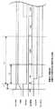
図1に示すように、本実施の形態に係わる映像信号伝送システムは、各種メディアからの映像/画像信号を選択して、モニタ14に表示するシステムである。(overall structure)
As shown in FIG. 1, the video signal transmission system according to the present embodiment is a system for selecting video / image signals from various media and displaying them on a
各種メディアとしては、例えば、TVアンテナ14a、ビデオデッキ14b、ビデオカメラ14c、パーソナルコンピュータ(PC)14d等があり、TVアンテナ14aから得られるテレビジョン信号、ビデオデッキ14bやビデオカメラ14cなどから得られるビデオ信号、PC14dから得られる映像信号などを適用することができる。 Examples of various media include a TV antenna 14a, a video deck 14b, a
各種メディアからの映像/画像信号は、セットトップボックス(STB)16と呼ばれる映像/画像信号を選択し映像信号として出力する装置により、各種インタフェースに対応した映像信号として出力し、光信号伝送装置10を介してプラズマディスプレイなどのモニタ14に表示するようになっている。 Video / image signals from various media are output as video signals corresponding to various interfaces by a device called a set top box (STB) 16 that selects video / image signals and outputs them as video signals. Is displayed on a
光信号伝送装置10が伝送する信号としては、映像信号の規格の1つに業界団体DDWGが策定したDVIなどが適用される。また、この他に音声情報やリモコン情報のやり取り等を行うためのDVI信号とは別の非DVI信号も適用される。 As a signal transmitted by the optical signal transmission apparatus 10, DVI or the like established by the industry group DDWG is applied to one of video signal standards. In addition, a non-DVI signal other than the DVI signal for exchanging voice information and remote control information is also applied.
DVI信号は、TMDS信号と呼ばれる4ビットの差動信号対である各色映像信号のR、G、B(TMDS data0、TMDS data1、TMDS data2)と画素クロック(TMDS Clock)と、ホスト(STB16)とモニタ14間でディスプレイ情報をやり取りするDDC ClockとDDC DataからなるDDC信号と、ホスト16とモニタ14間の接続状態を通知する5V Power信号とHPD信号とからなり、非DVI信号は、オーディオ信号やリモコン情報をやり取りする信号(ここではユーザデータと呼ぶ)がある。ここで各色映像信号と画素クロックとを合わせて映像信号と呼ぶことにする。 The DVI signal is a 4-bit differential signal pair called a TMDS signal, and R, G, B (TMDS data0, TMDS data1, TMDS data2), a pixel clock (TMDS Clock), and a host (STB16) of each color video signal. It consists of a DDC signal composed of DDC Clock and DDC Data for exchanging display information between the
(光信号伝送装置)
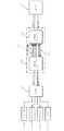
光信号伝送装置10は、図1及び図2に示すように、光送信モジュール18、光受信モジュール20、これらを接続する光ケーブル22からなり、少なくとも1つのデータ幅を持つ信号としての映像信号を光送信モジュール18から光ケーブル22を介して光受信モジュール20へ伝送する。(Optical signal transmission device)
As shown in FIGS. 1 and 2, the optical signal transmission device 10 includes an
(光送信モジュール)
光送信モジュール18は、DVI信号の映像データ等をパラレル/シリアル変換するパラレル/シリアル変換24を備え、パラレル/シリアル変換されたシリアル信号を光信号に変換するためのレーザ光源ドライバ(LDD)26に出力する。LDD26は変換されたシリアル信号に応じて変調した光を出力するためのBIAS信号とMOD信号をレーザ光源(LD)28に出力することでLD28を駆動する。LD28はLDD26から出力されるBIAS信号とMOD信号に基づいて変調した光で発光すると共に、LD28の発光光量をモニタするモニタPD30を含んで構成されている。モニタPD30は、LD28から発光される光量をモニタしてLDD26にフィードバックするようになっている。(Optical transmission module)
The
詳細には、ホスト16からモニタ14への信号は、映像信号、DDC信号、5V Power信号、オーディオ信号、ユーザデータ下り信号があり、光送信モジュール18に入力された信号は、パラレル/シリアル変換24によってパラレル信号からシリアル信号に変換された後、LDD26及びLD28によって電気−光変換されて光ケーブル22を介して光受信モジュール20に伝送される。なお、光送信モジュール18から光受信モジュールに伝送される光信号を主光信号という。 Specifically, the signal from the
主光信号は、映像信号を含むため、高速信号が必要であり、例えば、WXGA(1280×768画素)では2Gbps以上の伝送レートが必要となる。そのため高速変調が可能なレーザダイオード(例えば、富士ゼロックス社製VCSEL−AM−0001−C等)を用い、比較的大きなレーザ出力を必要とする。 Since the main optical signal includes a video signal, a high-speed signal is necessary. For example, WXGA (1280 × 768 pixels) requires a transmission rate of 2 Gbps or more. Therefore, a laser diode capable of high-speed modulation (for example, VCSEL-AM-0001-C manufactured by Fuji Xerox Co., Ltd.) is used, and a relatively large laser output is required.
また、光送信モジュール18は、光受信モジュール20のLED60から出力される光信号を受信するための受光素子(PD)32を備えており、PD32によって光信号が電気信号に変換される。PD32から出力される電気信号は、増幅器(AMP)34によって増幅され、シリアル/パラレル変換36によってパラレル信号に変換されてホスト16に出力されるようになっている。 The
この時、AMP34は光受信モジュール20から光を受信しているか否かを表すLED_LOS信号を後述する安全回路40及び第1の制御手段としてのスイッチ38に出力する。また、シリアル/パラレル変換36では、光受信モジュール20から伝送される信号に含まれる主光信号の受信状態を通知するLD_LOS(Loss Of Power)をRx_LOS信号として安全回路40に出力する。なお、光受信モジュール20から光送信モジュール18に伝送される光信号を副光信号という。なお、LED_LOS信号は正常状態でローレベル、未受信状態でハイレベルを出力する2値レベルの信号とされている。 At this time, the AMP 34 outputs an LED_LOS signal indicating whether or not light is received from the
(安全回路)
安全回路40は、光ケーブル22が未接続状態や光ケーブル22の破損等の場合にLD28の発光を停止するようにLDD26を制御する。詳細には、図3に示すように、データ確定回路42、パワーオン(PWR ON)検知回路44、映像情報検知回路46、状態検知回路48、及びDisable信号制御回路50を含んで構成されている。(Safety circuit)
The
データ確定回路42は、光受信モジュール18から伝送される副光信号のフレームレート(パラレル信号側のデータレート)で所定回数(例えば、3回等)連続して同一データが続いた時にデータのハイとローを変更してRx_LOS_D信号をDisable信号制御回路50及び状態検知回路48に出力する。すなわち、データ確定回路42では、同一データが所定回数連続した時に、当該データを確定するようになっている。 The data determination circuit 42 sets the data high when the same data continues for a predetermined number of times (for example, three times) at the frame rate (parallel signal side data rate) of the sub optical signal transmitted from the
状態検知回路48は、データ確定回路42から出力されるRx_LOS_D信号から主光信号の受信状態を検知して検知結果をDisable信号制御回路50に出力し、パワーオン検知回路44は、光送信モジュール18の電源投入を検知してDisable信号制御回路50に出力し、映像情報検知回路46は、映像信号中の映像情報を検知してDisable信号制御回路50に出力するようになっている。 The
Disable信号制御回路50は、入力される信号に基づいてDisable信号をLDD26に出力することでLDD26によるLD28の駆動を制御する。なお、Disable信号制御回路50は本発明の第2の制御手段に対応する。 The Disable
(光受信モジュール)
光受信モジュール20は、光送信モジュール18から光ケーブル22を介して受信した光を光−電気(OE)変換するOE変換部52で、光−電気変換した電気信号をシリアル/パラレル変換54に出力すると共に、該電気信号に含まれる主光信号の受信状態を表すLD_LOS信号をパラレル/シリアル変換56に出力する。シリアル/パラレル変換54でパラレル信号に変換された信号はモニタ14側に送信される。なお、LD_LOS信号は正常状態でローレベルとされ、光プラグの抜去時やファイバ断線による障害時など光信号を受信していないときには、ハイレベルを出力する2値レベル信号とされている。また、LD_LOS信号は、DDC Data信号、HPD信号、ユーザデータ上りと共に、モニタ14からホスト16への信号の1つとして、副光信号として伝送される。この副光信号は、LED60を光源とし、電源が投入されて光受信モジュール20がオン状態にある時は常に伝送状態(点滅を含む点灯状態)とされ、LED60の出力光量はレーザ安全上十分に低い光量に設定されている。これによって、LED60の発光により動作確認することも可能となる。(Optical receiver module)
The
OE変換部52は、光送信モジュール18から伝送される光信号を受信する受光素子(PD)62と、PD62によって変換された電気信号を電流−電圧変換するTIA(Transimpedance Amp)64と、電流−電圧変換された信号の電圧増幅を行うLA(Limitting Amp)66で構成されている。 The
また、光受信モジュール20から光送信モジュール18へ伝送される信号は、パラレル/シリアル変換56でシリアル信号に変換された後LED60を駆動するドライバ58に出力され、ドライバ58及びLED60によって電気−光変換されて光送信モジュール18に伝送される。 The signal transmitted from the
副光信号は、高速の伝送レートを必要としないためLED60を用いることができ、この時、可視光のLED60を用いることで、コネクタ装着時等において安全を確保しつつ動作確認を行うことができる。 Since the secondary light signal does not require a high-speed transmission rate, the
(光ケーブル)
光ケーブル22は、図4に示すように、主光信号用の光ファイバが接続された主光信号端子80と副光信号用の光ファイバが接続された副光信号端子82が共通のハウジング84により固定された光プラグ86と、該光プラグ86に接続された主光信号用光ファイバと副光信号用の光ファイバが束ねられた光ファイバ束22Aと、で構成されている。(Optical cable)
As shown in FIG. 4, the
すなわち、光プラグ86を光送信モジュール18及び光受信モジュール20に対して挿抜することにより、主光信号用の光ファイバと副光信号用の光ファイバの挿抜を同時に行うことが可能とされている。 That is, by inserting / removing the
(作用)
次に、光プラグ86挿抜時を含む光ケーブル22の障害時に、主光信号を停止する際の作用について説明する。(Function)
Next, the operation when the main optical signal is stopped at the time of failure of the
光受信モジュール20では、PD62による光電変換後の増幅過程(TIA64による電流−電圧変換及びLA66による電圧増幅)で、主光信号の受信状態を表すLD_LOS信号が出力され、パラレル/シリアル変換56によってシリアル信号に変換された後に、ドライバ58及びLED60によって電気−光変換されて光送信モジュール18に伝送される。なお、LD_LOS信号は、DDC Data信号、HPD信号、ユーザデータ上りと共に、モニタ14からホスト16への信号の1つとしてLED60を用いた副光信号として伝送される。 In the
光送信モジュール18に伝送された副光信号は、PD32によって光−電気変換され、AMP34によって所定ロジックレベルに増幅された後、シリアル/パラレル変換36によってパラレル信号に変換される。副光信号に含まれるLD_LOS信号は、光送信モジュール18内でRx_LOS信号として抽出されて安全回路40のデータ確定回路42に出力される。 The sub optical signal transmitted to the
安全回路40のデータ確定回路42では、副光信号のフレームレートで所定回数(例えば、3回等)同一データが続いた時に、Rx_LOS信号が確定されてRx_LOS_D信号としてDisable信号制御回路50に出力される。この回数は、断線などによるレーザ光の漏洩が起きてから安全回路40によりレーザ出力が遮断されるまでのレーザ出力のエネルギーが、安全性の面で十分低いエネルギーである回数である。すなわち、データ確定回路42によって副光信号のデータに誤りが有っても誤動作を防止することができる。 The data determination circuit 42 of the
そして、Disable信号制御回路50では、Rx_LOS_D信号に基づいて、LDD26にDisable信号が出力される。この時、Disable信号制御回路50では、Rx_LOS信号(Rx_LOS_D信号)がローレベルの状態の時、Disable信号をローレベルとして出力し、LDD26によってLD28を正常発光させ、Rx_LOS信号(Rx_LOS_D信号)がハイレベルの状態の時、Disable信号をハイレベルとして出力し、LDD26によってLD28の発光を停止することによって主光信号が停止される。このように処理することによって主光信号の受信状態に応じて主光信号を停止することができる。 Then, the Disable
さらに、光送信モジュール18では、PD32による光電変換後のAMP34による増幅過程で、副光信号の受信状態を表すLED_LOS信号が抽出され、LDD26への電源供給を行う第1の制御手段としてのスイッチ38の制御が行われる。この時、LED_LOS信号がローレベルの状態の時、LDD26への電源供給が制御されスイッチ38がオン状態とされて、LDD26によってLD28を正常発光させ、LED_LOS信号がハイレベルの状態の時、LDD26への電源供給が制御されてスイッチ38がオフ状態とされて、LD28の発光が停止されていることによって主光信号が停止される。 Further, in the
詳細には、光プラグ装着時、電源投入時、映像信号検出時の各タイミングで以下のように処理が行われる。 Specifically, the following processing is performed at each timing when the optical plug is mounted, when the power is turned on, and when the video signal is detected.
光プラグ装着時には、図5に示すタイミングチャートのように復帰シーケンスが行われる。なお、図5は、光プラグ86装着時の復帰シーケンスを示すタイミングチャートである。 When the optical plug is mounted, the return sequence is performed as shown in the timing chart of FIG. FIG. 5 is a timing chart showing a return sequence when the
光プラグ86が光送信モジュール18及び光受信モジュール20に装着されると、光送信モジュール18ではPD32によって副光信号を感知し、副光信号の受信状態を表すLED_LOSがハイレベルからローレベルに変化する。この動作によってスイッチ38がオンされて(PWRが徐々に立ち上がって)LDD26の電源がオン状態となり、Disable信号制御回路50から出力されるDisable信号によりLD28からのレーザ光の出力が制御されるようになる。 When the
Disable信号制御回路50は、LED_LOSがローレベルになった後、LDD26が動作可能にあるT1後(例えば、100ms)にT2の期間(例えば10ms)の間、Disable信号をローレベルにして主光信号を発光させる。ここで、T1はLDD26の電源がONして動作を開始できるのに十分な時間であり、T2はLD28の発光を許可してから主光信号の受信状態が確認できるのに十分でかつ安全性の面で十分低いエネルギーである時間である。主光信号を発光させている間にLD_LOS信号がハイレベルからローレベルに変化することによりRx_LOS_D信号がハイレベルからローレベルに変化した場合に、状態検知回路48によって光ケーブル22が正常に接続されて動作可能と判断し、正常動作に移行する。 The Disable
T2の期間内にRx_LOS_D信号がローレベルに変化しなかった場合には、T3の周期(例えば、500ms)で例えば10回程度繰り返し光ケーブル22の接続状態を確認し、Rx_LOS_Dがローレベルに変化した場合に、正常動作に移行する。ここで、T3は安全性の面で十分低い平均エネルギーである時間である。Rx_LOS_Dがハイレベルのままの時は、Disable信号をハイレベルにして主光信号を停止した状態で復帰シーケンスを終了する。 When the Rx_LOS_D signal does not change to the low level within the period of T2, the connection state of the
また、電源投入時には、図6に示すタイミングチャートのように立上げシーケンスが行われる。なお、図6は、電源投入時の立上げシーケンスを示すタイミングチャートである。 When the power is turned on, a startup sequence is performed as shown in the timing chart of FIG. FIG. 6 is a timing chart showing the startup sequence when the power is turned on.
光送信モジュール18及び光受信モジュール20の電源が供給され、光送信モジュール18では、パワーオン検知回路44によって電源供給が検知されると共に、Disable信号が電源電圧の上昇に伴い徐々に立ち上がってハイレベルになる。一方、光受信モジュール20ではLD_LOS信号が電源電圧の上昇に伴い徐々にハイレベルになると共に、LED60が発光を開始し副光信号の伝送が開始される。この時、LED_LOS信号のローレベルを検知すると、スイッチ38がオンされて(PWRが徐々に立ち上がって)LDD26の電源がオン状態となり、Disable信号制御回路50から出力されるDisable信号によりLD28からのレーザ光の出力が制御されるようになり、上述の光プラグ86装着時の復帰シーケンスと同様に、光ケーブル22の接続状態の確認が行われる。 The
Disable信号制御回路50は、LED_LOSのローレベルを検知した後、LDD26が動作可能にあるT1後(例えば、100ms)にT2の期間(例えば10ms)の間、Disable信号をローレベルにして主光信号を発光させる。その間にLD_LOS信号がハイレベルからローレベルに変化することによりRx_LOS_D信号がハイレベルからローレベルに変化した場合に、状態検知回路48によって光ケーブルが正常に接続されて動作可能と判断し、正常動作に移行する。 The Disable
T2の期間内にRx_LOS_D信号がローレベルに変化しなかった場合には、T3の周期(例えば、500ms)で例えば10回程度繰り返し光ケーブル22の接続状態を確認し、Rx_LOS_Dがローレベルに変化した場合に、正常動作に移行する。Rx_LOS_Dがハイレベルのままの時は、Disable信号をハイレベルにして主光信号を停止した状態で復帰シーケンスを終了する。 When the Rx_LOS_D signal does not change to the low level within the period of T2, the connection state of the
更に、映像情報検出時には、図7に示すタイミングチャートのように復帰シーケンスが行われる。なお、図7は、映像情報検出時の復帰シーケンスを示すタイミングチャートである。 Furthermore, when video information is detected, a return sequence is performed as shown in the timing chart of FIG. FIG. 7 is a timing chart showing a return sequence when video information is detected.
映像情報検知回路46は、TMDS信号の出力状態を検知する。この時、TMDS信号が検知されていない場合には、映像信号が来ていない状態(無信号状態)と判断して、Disable信号をハイレベルにして主光信号の出力を停止する。これによって、不要時のレーザ発光が停止され、消費電力を低減することができると共に、LD28の寿命を延ばすことが可能となる。 The video
また、TMDS信号が映像情報検知回路46によって検知されると、まず光ケーブル22の接続状態の確認を行う。映像情報検知回路46によって映像情報が検知されてからT5(例えば1ms)の後、Disable信号をローレベルにし、上述の光プラグ86装着時の復帰シーケンスと同様に、光ケーブル22の接続状態の確認が行われる。なお、図7では光ケーブル22の接続が維持された状態、すなわち、LED_LOSがローベルを継続した状態を示す。 When the TMDS signal is detected by the video
Disable信号制御回路50は、LED_LOSのローレベルを検知した後(図7では上述したようにローレベルが継続した状態を示す)、LDD26が動作可能にあるT2の期間(例えば10ms)の間、Disable信号をローレベルにして主光信号を発光させる。その間にLD_LOS信号がハイレベルからローレベルに変化することによりRx_LOS_D信号がハイレベルからローレベルに変化した場合に、状態検知回路48によって光ケーブルが正常に接続されて動作可能と判断し、正常動作に移行する。 The Disable
T2の期間内にRx_LOS_D信号がローレベルに変化しなかった場合には、T3の周期(例えば、500ms)で例えば10回程度繰り返し光ケーブル22の接続状態を確認し、Rx_LOS_Dがローレベルに変化した場合に、正常動作に移行する。Rx_LOS_Dがハイレベルのままの時は、Disable信号をハイレベルにして主光信号を停止した状態で復帰シーケンスを終了する。 When the Rx_LOS_D signal does not change to the low level within the period of T2, the connection state of the
このように本実施の形態の映像信号伝送システムにおける光信号伝送装置10では、主光信号の受信状態をデータとして含む副光信号が未受信、及び主光信号の受信状態が未受信の少なくとも一方の場合に、主光信号の出力を停止するように主光信号の出力を制御することによって、光ケーブル22の未接続や損傷等によるレーザ光の漏出を確実に防止することができる。 As described above, in the optical signal transmission device 10 in the video signal transmission system according to the present embodiment, at least one of the sub optical signal including the main optical signal reception state as data is not received and the main optical signal reception state is not received. In this case, by controlling the output of the main light signal so as to stop the output of the main light signal, leakage of the laser light due to unconnected or damaged
また、副光信号が未受信の場合に主光信号を停止する制御と、主光信号の受信状態が未受信の場合に主光信号を停止する制御と、2段制御としているので、何れか一方が故障しても他方によってレーザ光の漏出を防止することができ、安全性を向上することができる。 In addition, either the control to stop the main optical signal when the sub optical signal is not received, the control to stop the main optical signal when the reception state of the main optical signal is not received, or two-stage control, either Even if one of them fails, the other can prevent leakage of the laser beam, and safety can be improved.
続いて、上記の実施の形態の変形例について説明する。 Subsequently, a modification of the above embodiment will be described.
上記の実施の形態では、映像を含む全てのDVI信号をパラレル/シリアル変換してから光受信モジュールに伝送するようにしたが、変形例では、DVI信号のうち映像信号はパラレル/シリアル変換せずに光受信モジュールに伝送するものである。なお、上記の実施の形態と同一構成について同一符号を付して説明する。 In the above embodiment, all DVI signals including video are parallel / serial converted and then transmitted to the optical receiving module. However, in the modification, the video signal of the DVI signal is not parallel / serial converted. Are transmitted to the optical receiver module. The same components as those in the above embodiment will be described with the same reference numerals.
(全体構成)
図8に示すように、変形例の映像信号伝送システムは、上記の実施の形態と同様に、各種メディアからの映像/画像信号を選択して、モニタ14に表示するシステムである。(overall structure)
As shown in FIG. 8, the video signal transmission system of the modification is a system that selects video / image signals from various media and displays them on the
各種メディアとしては、上記の実施の形態で説明したように、例えば、TVアンテナ14a、ビデオデッキ14b、ビデオカメラ14c、パーソナルコンピュータ(PC)14d等があり、TVアンテナ14aから得られるテレビジョン信号、ビデオデッキ14bやビデオカメラ14cなどから得られるビデオ信号、PC14dから得られる映像信号などを適用することができる。 As the various media, as described in the above embodiment, for example, there are a TV antenna 14a, a video deck 14b, a
各種メディアからの映像/画像信号は、セットトップボックス(STB)16と呼ばれる映像/画像信号を選択し映像信号として出力する装置により、各種インタフェースに対応した映像信号として出力し、光信号伝送装置11を介してプラズマディスプレイなどのモニタ14に表示するようになっている。 Video / image signals from various media are output as video signals corresponding to various interfaces by a device called a set top box (STB) 16 that selects video / image signals and outputs them as video signals. Is displayed on a
光信号伝送装置11が伝送する信号としては、上記の実施の形態と同様に、映像信号の規格の1つに業界団体DDWGが策定したDVIなどが適用される。また、この他に音声情報やリモコン情報のやり取り等を行うためのDVI信号とは別の非DVI信号も適用される。 As the signal transmitted by the optical signal transmission device 11, DVI established by the industry group DDWG is applied to one of the video signal standards, as in the above embodiment. In addition, a non-DVI signal other than the DVI signal for exchanging voice information and remote control information is also applied.
DVI信号は、TMDS信号と呼ばれる4ビットの差動信号対である各色映像信号のR、G、B(TMDS data0、TMDS data1、TMDS data2)と画素クロック(TMDS Clock)と、ホスト(STB16)とモニタ14間でディスプレイ情報をやり取りするDDC ClockとDDC DataからなるDDC信号と、ホスト16とモニタ14間の接続状態を通知する5V Power信号とHPD信号とからなり、非DVI信号は、オーディオ信号やリモコン情報をやり取りする信号(ここではユーザデータと呼ぶ)がある。ここで各色映像信号と画素クロックとを合わせて映像信号と呼ぶことにする。 The DVI signal is a 4-bit differential signal pair called a TMDS signal, and R, G, B (TMDS data0, TMDS data1, TMDS data2), a pixel clock (TMDS Clock), and a host (STB16) of each color video signal. It consists of a DDC signal composed of DDC Clock and DDC Data for exchanging display information between the
(光信号伝送装置)
光信号伝送装置11は、図8及び図9に示すように、光送信モジュール19、光受信モジュール21、これらを接続する光ケーブル22からなり、少なくとも1つのデータ幅を持つ信号としての映像信号を光送信モジュール18から光ケーブル22を介して光受信モジュール21へ伝送する。(Optical signal transmission equipment)
As shown in FIGS. 8 and 9, the optical signal transmission device 11 includes an
(光送信モジュール)
光送信モジュール19は、DVI信号のうち映像信号を電気−光変換するE/O変換70を各映像信号毎に備えており、ホスト16側から送信されてくる映像信号を電気−光変換して光受信モジュール21に光ケーブル22を介して伝送するようになっており、各E/O変換70は、LDを用いて光受信モジュール21に光信号を伝送する。すなわち、映像信号を伝送するためのE/O変換70は、上記の実施の形態のLDD26、LD28、及びPD30等を含んで構成されている。なお、光ケーブル22は、各映像信号に対応して設けられている。(Optical transmission module)
The
映像信号以外のDVI信号とDVI以外の信号は、上記の実施の形態と同様に、パラレル/シリアル変換24によってシリアル信号に変換した後に、E/O変換72によって電気−光変換して光受信モジュール21に伝送するようになっている。なお、映像信号以外のDVI信号及びDVI以外の信号は、高速信号ではないので、E/O変換72はLEDを適用して光伝送する。例えば、上記の実施の形態におけるドライバ58及びLED60等を適用することができる。 The DVI signal other than the video signal and the signal other than DVI are converted into a serial signal by the parallel /
すなわち、ホスト16からモニタ14への信号は、上記の実施の形態で説明したように、映像信号、DDC信号、5V Power信号、オーディオ信号、ユーザデータ下り信号があり、光送信モジュール19に入力された信号のうちの各映像信号は、対応する各E/O変換70によって電気−光変換された後、光ケーブル22を介して光受信モジュール21に伝送され、残りの信号(DDC信号、5V Power信号、オーディオ信号、ユーザデータ下り信号)は、パラレル−シリアル変換された後に、E/O変換72によって電気−光変換されて光受信モジュール21に伝送される。なお、変形例では、各色映像信号(TMDS data0、TMDS data1、TMDS data2)と画素クロック(TMDS Clock)が主光信号に対応する。 That is, as described in the above embodiment, the signal from the
主光信号は、映像信号からなるため、高速信号が必要であり、例えば、UXGA(1600×1200画素)では1.62Gbpsの伝送レートが必要となる。そのため高速変調が可能なレーザダイオード(例えば、富士ゼロックス社製VCSEL−AM−0001−C等)を用い、比較的大きなレーザ出力を必要とする。 Since the main optical signal is a video signal, a high-speed signal is required. For example, UXGA (1600 × 1200 pixels) requires a transmission rate of 1.62 Gbps. Therefore, a laser diode capable of high-speed modulation (for example, VCSEL-AM-0001-C manufactured by Fuji Xerox Co., Ltd.) is used, and a relatively large laser output is required.
また、光送信モジュール19は、光受信モジュール21の後述するE/O変換94から出力される光信号を受信して光−電気変換するO/E変換74を備えている。なお、当該O/E変換74は、上記の実施の形態におけるPD32及びAMP34等を適用することができる。 The
O/E変換74によって電気信号に変換された信号は、上記の実施の形態と同様に、シリアル/パラレル変換36によってパラレル信号に変換されてホスト16に出力されるようになっている。 The signal converted into the electric signal by the O / E conversion 74 is converted into a parallel signal by the serial /
また、O/E変換74によって電気変換された信号から光受信モジュール21から光を受信しているか否かを表すLED_LOS信号を抽出して安全回路40及び第1の制御手段としてのスイッチ38に出力する。また、シリアル/パラレル変換36では、光受信モジュール21から伝送される信号に含まれる主光信号の受信状態を通知するLD_LOS(Loss Of Power)をRx_LOS信号として安全回路40に出力する。なお、光受信モジュール21から光送信モジュール19に伝送される光信号を副光信号という。また、LED_LOS信号は正常状態でローレベル、未受信状態でハイレベルを出力する2値レベルの信号とされている。 Further, an LED_LOS signal indicating whether or not light is received from the
(安全回路)
安全回路40は、各映像信号が安全回路40の映像情報検知回路46に直接入力される点と、Disable信号制御回路50から出力されるDisable信号が各E/O変換70にそれぞれ出力される点以外は同一構成であるので説明を省略する。(Safety circuit)
In the
(光受信モジュール)
光受信モジュール21は、光送信モジュール19から光ケーブル22を介して受信した光を光−電気変換するO/E変換90を備えており、O/E変換90によって変換されて電気信号は、モニタ14側に直接出力されるようになっている。(Optical receiver module)
The
変形例では、主光信号を4つのO/E変換90で受信するため、それぞれの主光信号の受信状態(LD_LOS0、LD_LOS1、LD_LOS2、LD_LOS3)はOR回路96を介してパラレル/シリアル変換56に出力されるようになっている。すなわち、何れか1つでも主光信号の受信状態が未受信である場合等では、OR回路96はLD_LOS信号として主光信号の受信状態が未受信であることを表す信号を出力する。本実施の形態では、上記の実施の形態で説明したように、LD_LOS信号は正常状態でローレベルとされ、光プラグの抜去時やファイバ断線による障害時など光信号を受信していないときには、ハイレベルを出力する。 In the modified example, since the main optical signal is received by the four O /
また、光送信モジュール19から伝送される映像信号以外の信号及び光受信モジュール21から光送信モジュール19へ伝送する副光信号の伝送経路については、上記の実施の形態と同様であるので説明を省略する。 Further, the transmission path of the signals other than the video signal transmitted from the
(光ケーブル)
光ケーブル22は、各映像信号に対応して光ファイバが上記の実施の形態に対して増加するに伴って端子が増加する点以外は、基本的には同一構成とされている。(Optical cable)
The
すなわち、光プラグを光送信モジュール19及び光受信モジュール21に対して挿抜することにより、主光信号用の光ファイバと副光信号用の光ファイバの挿抜を同時に行うことが可能とされている。 That is, by inserting and removing the optical plug with respect to the
以上のように構成しても光プラグ挿抜時を含む光ケーブル22の障害時に主光信号を停止する際には、上記の実施の形態と同様に動作させることができる。すなわち、変形例のように光信号伝送装置11を構成しても、光ケーブル22の未接続や損傷等によるレーザ光の漏出を防止することができる。そして、上記の実施の形態と同様に主光信号を停止する際には2段制御であるので、何れか一方が故障しても他方によってレーザ光の漏出を防止することができ、安全性を向上することができる。 Even when configured as described above, when the main optical signal is stopped when the
また、変形例では、高速信号である映像信号がパラレル化されるので、上記の実施の形態よりも大画面/大容量の映像信号を伝送することが可能となる。 In the modification, since the video signal which is a high-speed signal is parallelized, it is possible to transmit a video signal having a larger screen / larger capacity than the above-described embodiment.
なお、上記の実施の形態では、主光信号を伝送するための光ファイバと副光信号を伝送するための光ファイバとをそれぞれ設けるようにしたが、主光信号と副光信号を時分割で伝送したり、主光信号と副光信号を分離する機能等を設ける等が必要となるが、1本の光ファイバだけで構成するようにしてもよい。 In the above embodiment, the optical fiber for transmitting the main optical signal and the optical fiber for transmitting the sub optical signal are provided, respectively. However, the main optical signal and the sub optical signal are time-divisionally divided. Although it is necessary to provide a function of transmitting or separating the main optical signal and the sub optical signal, etc., it may be configured by only one optical fiber.
10、11 光信号伝送装置
18、19 光送信モジュール
20、21 光受信モジュール
22 光ケーブル
26 LDD
28 LD
38 スイッチ
40 安全回路
42 データ確定回路
44 パワーオン検知回路
46 映像情報検知回路
48 状態検知回路
50 Disable信号制御回路
52 OE変換部
58 ドライバ
60 LED
70、72、94 E/O変換
74、90 O/E変換
62 PD
64 TIA
66 LA
86 光プラグ
96 OR回路10, 11 Optical
28 LD
38
70, 72, 94 E / O conversion 74, 90 O / E conversion 62 PD
64 TIA
66 LA
86 Optical plug 96 OR circuit
Claims (8)
Translated fromJapanese前記主光信号を受信する主光信号受信手段と、前記主光信号受信手段によって前記主光信号を受信しているか否かに基づく前記受信状態を表す信号を含む前記副光信号を電源オン状態にある時に常に伝送状態としてレーザ安全上十分に低い光量で送信する副光信号送信手段と、を有する光受信モジュールと、
前記光送信モジュールと前記光受信モジュール間を接続し、双方向の光伝送を行うための光ケーブルと、
を備え、
前記副光信号受信手段によって前記副光信号を受信してから、前記主光信号送信手段による前記主光信号の送信を開始して、前記制御手段による制御へ移行する光信号伝送装置。A main light signal transmitting means for transmitting a main light signal including at least a video signal or an image signal using a laser light source, and a sub light signal including a reception state indicating whether or not the main light signal is received. When the sub optical signal is not received by the optical signal receiving unit and the sub optical signal receiving unit, and when the reception state included in the sub optical signal received by the sub optical signal receiving unit indicates unreceived A control means for controlling the main optical signal transmission means so as to stop the output of the main optical signal in at least one case; and
A main optical signal receiving means for receiving the main optical signal, and a power-on state of the sub optical signal including a signal indicating the reception state based on whether or not the main optical signal is received by the main optical signal receiving means A sub-optical signal transmitting means for always transmitting with a sufficiently low light quantity for laser safety as a transmission state when there is a light receiving module,
An optical cable for connecting the optical transmission module and the optical reception module to perform bidirectional optical transmission;
With
An optical signal transmission apparatus that, after receiving the sub optical signal by the sub optical signal receiving means, starts transmitting the main optical signal by the main optical signal transmitting means and shifts to control by the control means.
Priority Applications (2)
| Application Number | Priority Date | Filing Date | Title |
|---|---|---|---|
| JP2005014005AJP4665528B2 (en) | 2004-07-06 | 2005-01-21 | Optical signal transmission device |
| US11/068,923US7433595B2 (en) | 2004-07-06 | 2005-03-02 | Optical signal transmission apparatus and optical signal transmission method |
Applications Claiming Priority (2)
| Application Number | Priority Date | Filing Date | Title |
|---|---|---|---|
| JP2004199225 | 2004-07-06 | ||
| JP2005014005AJP4665528B2 (en) | 2004-07-06 | 2005-01-21 | Optical signal transmission device |
Publications (2)
| Publication Number | Publication Date |
|---|---|
| JP2006050530A JP2006050530A (en) | 2006-02-16 |
| JP4665528B2true JP4665528B2 (en) | 2011-04-06 |
Family
ID=35541508
Family Applications (1)
| Application Number | Title | Priority Date | Filing Date |
|---|---|---|---|
| JP2005014005AExpired - Fee RelatedJP4665528B2 (en) | 2004-07-06 | 2005-01-21 | Optical signal transmission device |
Country Status (2)
| Country | Link |
|---|---|
| US (1) | US7433595B2 (en) |
| JP (1) | JP4665528B2 (en) |
Families Citing this family (40)
| Publication number | Priority date | Publication date | Assignee | Title |
|---|---|---|---|---|
| US7347632B2 (en) | 2003-12-12 | 2008-03-25 | Mina Farr | Optical connectors for electronic devices |
| US7321946B2 (en)* | 2004-07-07 | 2008-01-22 | Infocus Corporation | Link extender having equalization circuitry |
| US7706692B2 (en)* | 2004-09-29 | 2010-04-27 | Finisar Corporation | Consumer electronics with optical communication interface |
| US7548675B2 (en) | 2004-09-29 | 2009-06-16 | Finisar Corporation | Optical cables for consumer electronics |
| US20060280055A1 (en)* | 2005-06-08 | 2006-12-14 | Miller Rodney D | Laser power control and device status monitoring for video/graphic applications |
| US7331819B2 (en)* | 2005-07-11 | 2008-02-19 | Finisar Corporation | Media converter |
| US7729618B2 (en)* | 2005-08-30 | 2010-06-01 | Finisar Corporation | Optical networks for consumer electronics |
| US7860398B2 (en)* | 2005-09-15 | 2010-12-28 | Finisar Corporation | Laser drivers for closed path optical cables |
| US7787765B2 (en)* | 2005-12-21 | 2010-08-31 | International Business Machines Corporation | Method and apparatus device for initializing an end-to-end link in a fiber optic communications system |
| US7826745B2 (en)* | 2005-12-21 | 2010-11-02 | International Business Machines Corporation | Open fiber control and loss of light propagation in time division multiplexed inter-system channel link |
| JP4893044B2 (en)* | 2006-03-20 | 2012-03-07 | ソニー株式会社 | Optical transmission unit and optical cable inspection method |
| US7712976B2 (en)* | 2006-04-10 | 2010-05-11 | Finisar Corporation | Active optical cable with integrated retiming |
| US7445389B2 (en)* | 2006-04-10 | 2008-11-04 | Finisar Corporation | Active optical cable with integrated eye safety |
| US7876989B2 (en)* | 2006-04-10 | 2011-01-25 | Finisar Corporation | Active optical cable with integrated power |
| US7401985B2 (en)* | 2006-04-10 | 2008-07-22 | Finisar Corporation | Electrical-optical active optical cable |
| US8083417B2 (en)* | 2006-04-10 | 2011-12-27 | Finisar Corporation | Active optical cable electrical adaptor |
| US7499616B2 (en) | 2006-04-10 | 2009-03-03 | Finisar Corporation | Active optical cable with electrical connector |
| US7778510B2 (en)* | 2006-04-10 | 2010-08-17 | Finisar Corporation | Active optical cable electrical connector |
| JP2007300490A (en)* | 2006-05-01 | 2007-11-15 | Sony Corp | Digital video transmitter, digital video receiver, digital video transmission system, and digital video transmission method |
| JP2007300487A (en)* | 2006-05-01 | 2007-11-15 | Sony Corp | Optical transmission unit and optical cable inspection method |
| TW200805912A (en)* | 2006-07-05 | 2008-01-16 | Apac Opto Electronics Inc | Transmission apparatus with fiber high-definition digital video data interface |
| US8769171B2 (en)* | 2007-04-06 | 2014-07-01 | Finisar Corporation | Electrical device with electrical interface that is compatible with integrated optical cable receptacle |
| US8244124B2 (en) | 2007-04-30 | 2012-08-14 | Finisar Corporation | Eye safety mechanism for use in optical cable with electrical interfaces |
| JP4718595B2 (en)* | 2007-12-27 | 2011-07-06 | パナソニック株式会社 | Wireless communication system and portable terminal device |
| US8391708B1 (en)* | 2008-07-11 | 2013-03-05 | Finisar Corporation | Laser eye safety and fiber receptacle presence detection |
| JP2010166546A (en)* | 2008-12-15 | 2010-07-29 | Fuji Xerox Co Ltd | Signal transmitting device, transmitter, and receiver |
| CN102269599A (en)* | 2010-06-02 | 2011-12-07 | 新科实业有限公司 | Optical component and manufacturing method thereof |
| JP5642484B2 (en)* | 2010-09-30 | 2014-12-17 | オリンパス株式会社 | Endoscope system |
| WO2012093431A1 (en)* | 2011-01-07 | 2012-07-12 | パナソニック株式会社 | Optical transmission system |
| JP5884370B2 (en)* | 2011-09-28 | 2016-03-15 | 富士ゼロックス株式会社 | Optical transmission / reception system and transmission / reception apparatus |
| JP6010908B2 (en)* | 2012-01-06 | 2016-10-19 | 富士ゼロックス株式会社 | Transmission / reception system and program |
| US9160451B2 (en)* | 2012-03-06 | 2015-10-13 | Sae Magnetics (H.K.) Ltd. | Active optical cable connector plug and active optical cable using same |
| WO2013172072A1 (en)* | 2012-05-18 | 2013-11-21 | 日本電気株式会社 | Optical system, optical deveice, and optical connection method |
| US8712196B2 (en)* | 2012-07-20 | 2014-04-29 | Avago Technologies General Ip (Singapore) Pte. Ltd. | Optical cable plug-in detection |
| JP5994486B2 (en)* | 2012-08-27 | 2016-09-21 | 富士通株式会社 | Optical transmission system, optical transmission method, and optical module |
| JP2016012827A (en)* | 2014-06-30 | 2016-01-21 | 株式会社日立製作所 | Optical transmitting/receiving device |
| US9497525B2 (en)* | 2014-09-12 | 2016-11-15 | Corning Optical Communications LLC | Optical engines and optical cable assemblies having electrical signal conditioning |
| KR20180067108A (en)* | 2016-12-12 | 2018-06-20 | 삼성전자주식회사 | Display apparatus presenting status of external electronic apparatus and controlling method thereof |
| CN118473108A (en)* | 2017-09-28 | 2024-08-09 | Wi-电荷有限公司 | Error-safety optical wireless power supply |
| CN107894621A (en)* | 2017-11-17 | 2018-04-10 | 深圳门海安全技术有限公司 | Door and window state detection mechanism includes the system and its detection method of the door and window state detection mechanism |
Family Cites Families (21)
| Publication number | Priority date | Publication date | Assignee | Title |
|---|---|---|---|---|
| US4994675A (en)* | 1989-04-28 | 1991-02-19 | Rebo Research, Inc. | Method and apparatus for checking continuity of optic transmission |
| JPH0380637A (en)* | 1989-08-23 | 1991-04-05 | Fujitsu Ltd | Laser light cutoff control method |
| JPH0394529A (en)* | 1989-09-07 | 1991-04-19 | Nec Corp | Optical output automatic interruption system |
| US5095308A (en)* | 1990-01-09 | 1992-03-10 | Southern Marine Research, Inc. | Transceiver with battery saver and method of using same |
| US5005939A (en)* | 1990-03-26 | 1991-04-09 | International Business Machines Corporation | Optoelectronic assembly |
| JPH05122154A (en)* | 1991-10-28 | 1993-05-18 | Fujitsu Ltd | Optical output control system in optical transmission system |
| JPH05244099A (en) | 1992-02-27 | 1993-09-21 | Fujitsu Ltd | Optical communication system |
| US5315679A (en)* | 1992-04-27 | 1994-05-24 | International Business Machines Corporation | Optical fibers duplex connector assembly |
| JPH0667391A (en) | 1992-08-17 | 1994-03-11 | Konica Corp | Heat-developable photosensitive material |
| JPH0730495A (en)* | 1993-07-09 | 1995-01-31 | Sony Corp | Two-way optical communication device |
| KR100200825B1 (en)* | 1994-03-31 | 1999-06-15 | 윤종용 | Auto power off circuit for picture record and reproduce device |
| JPH0897773A (en)* | 1994-09-27 | 1996-04-12 | Fujitsu Ltd | Optical signal transmission device |
| US5661583A (en)* | 1995-10-25 | 1997-08-26 | The United States Of America As Represented By The Secretary Of The Navy | Fiber optical data interface system |
| US6009470A (en)* | 1997-09-10 | 1999-12-28 | Lsi Logic Corporation | Encoded multi-media terminal |
| US6359708B1 (en)* | 1997-09-18 | 2002-03-19 | Lucent Technologies Inc. | Optical transmission line automatic power reduction system |
| US6504630B1 (en)* | 1998-12-04 | 2003-01-07 | Lucent Technologies Inc. | Automatic power shut-down arrangement for optical line systems |
| JP2001185783A (en) | 1999-12-27 | 2001-07-06 | Nec Corp | Device and method or preventing laser beam unnecessary leakage and optical communication system using the same |
| JP2003032189A (en)* | 2001-07-17 | 2003-01-31 | Opnext Japan Inc | Optical transmitter-receiver and optical transmission system |
| US7092630B2 (en)* | 2001-11-16 | 2006-08-15 | Avago Technologies Fiber Ip(Singapore) Ptd. Ltd. | Open fiber control for optical transceivers |
| JP3745279B2 (en)* | 2002-01-16 | 2006-02-15 | 日本航空電子工業株式会社 | DVI optical extension cable connection and external power input confirmation system |
| JP2004023464A (en)* | 2002-06-17 | 2004-01-22 | Nec Engineering Ltd | Optical output stop system for optical transmission apparatus |
- 2005
- 2005-01-21JPJP2005014005Apatent/JP4665528B2/ennot_activeExpired - Fee Related
- 2005-03-02USUS11/068,923patent/US7433595B2/ennot_activeExpired - Fee Related
Also Published As
| Publication number | Publication date |
|---|---|
| US20060008276A1 (en) | 2006-01-12 |
| US7433595B2 (en) | 2008-10-07 |
| JP2006050530A (en) | 2006-02-16 |
Similar Documents
| Publication | Publication Date | Title |
|---|---|---|
| JP4665528B2 (en) | Optical signal transmission device | |
| JP4569195B2 (en) | Signal transmission device | |
| JP5417151B2 (en) | Optical wiring cable and optical power control method | |
| KR100402409B1 (en) | Digital Vidio Signal Interface Module For Transmitting Long Distance | |
| US10326245B1 (en) | Light illuminating data communication cable | |
| US7860398B2 (en) | Laser drivers for closed path optical cables | |
| US9002198B2 (en) | Optical transmission system | |
| US11750294B2 (en) | Optical communication interface system | |
| KR20210148147A (en) | Battery triggering for activation of optical data interconnection systems | |
| US20210314656A1 (en) | HDMI Apparatus Using Optical Communication | |
| US20160020912A1 (en) | Optical cable assemblies with low-speed data pass-through architecture and sleep mode operation | |
| CN106657941B (en) | Photoelectric hybrid DisplayPort remote transmission device and method | |
| US20100150552A1 (en) | Optical/electrical composite cable, optical/electrical composite cable connection device and optical/electrical composite cable drive method | |
| CN107276675B (en) | USB3.0 HUB based on optical fiber long-distance transmission | |
| JP2007053675A (en) | Optical signal transmission apparatus | |
| EP1496629B1 (en) | Light transmitter-receiver apparatus | |
| CN105471497B (en) | Method and device for predicting service life of parallel optical module in open-loop mode | |
| JP2010246147A (en) | Signal transmission device | |
| JP2009253654A (en) | Optical communication system | |
| CN107332619B (en) | USB3.1 HUB based on optical fiber long-distance transmission | |
| EP1662787A2 (en) | Signal transmitting and receiving device and signal transmitting and receiving method | |
| JP2004179733A (en) | Light amount adjusting device of light source for supplying optical signal used in opto-electric hybrid communication system | |
| JP4470560B2 (en) | Signal transmission device | |
| EP4125229A1 (en) | Optical communication interface system | |
| JP5286749B2 (en) | Optical digital video cable |
Legal Events
| Date | Code | Title | Description |
|---|---|---|---|
| A621 | Written request for application examination | Free format text:JAPANESE INTERMEDIATE CODE: A621 Effective date:20071219 | |
| A977 | Report on retrieval | Free format text:JAPANESE INTERMEDIATE CODE: A971007 Effective date:20091110 | |
| A131 | Notification of reasons for refusal | Free format text:JAPANESE INTERMEDIATE CODE: A131 Effective date:20091201 | |
| A521 | Request for written amendment filed | Free format text:JAPANESE INTERMEDIATE CODE: A523 Effective date:20100128 | |
| A131 | Notification of reasons for refusal | Free format text:JAPANESE INTERMEDIATE CODE: A131 Effective date:20100706 | |
| A521 | Request for written amendment filed | Free format text:JAPANESE INTERMEDIATE CODE: A523 Effective date:20100902 | |
| A131 | Notification of reasons for refusal | Free format text:JAPANESE INTERMEDIATE CODE: A131 Effective date:20101005 | |
| A521 | Request for written amendment filed | Free format text:JAPANESE INTERMEDIATE CODE: A523 Effective date:20101026 | |
| TRDD | Decision of grant or rejection written | ||
| A01 | Written decision to grant a patent or to grant a registration (utility model) | Free format text:JAPANESE INTERMEDIATE CODE: A01 Effective date:20101214 | |
| A01 | Written decision to grant a patent or to grant a registration (utility model) | Free format text:JAPANESE INTERMEDIATE CODE: A01 | |
| A61 | First payment of annual fees (during grant procedure) | Free format text:JAPANESE INTERMEDIATE CODE: A61 Effective date:20101227 | |
| FPAY | Renewal fee payment (event date is renewal date of database) | Free format text:PAYMENT UNTIL: 20140121 Year of fee payment:3 | |
| R150 | Certificate of patent or registration of utility model | Ref document number:4665528 Country of ref document:JP Free format text:JAPANESE INTERMEDIATE CODE: R150 Free format text:JAPANESE INTERMEDIATE CODE: R150 | |
| LAPS | Cancellation because of no payment of annual fees |