JP4664785B2 - Disc and cell counting and observation apparatus using optical disc using optical disc - Google Patents
Disc and cell counting and observation apparatus using optical disc using optical discDownload PDFInfo
- Publication number
- JP4664785B2 JP4664785B2JP2005269818AJP2005269818AJP4664785B2JP 4664785 B2JP4664785 B2JP 4664785B2JP 2005269818 AJP2005269818 AJP 2005269818AJP 2005269818 AJP2005269818 AJP 2005269818AJP 4664785 B2JP4664785 B2JP 4664785B2
- Authority
- JP
- Japan
- Prior art keywords
- disk
- counting
- unit
- cells
- test solution
- Prior art date
- Legal status (The legal status is an assumption and is not a legal conclusion. Google has not performed a legal analysis and makes no representation as to the accuracy of the status listed.)
- Expired - Fee Related
Links
Images


Classifications
- C—CHEMISTRY; METALLURGY
- C12—BIOCHEMISTRY; BEER; SPIRITS; WINE; VINEGAR; MICROBIOLOGY; ENZYMOLOGY; MUTATION OR GENETIC ENGINEERING
- C12M—APPARATUS FOR ENZYMOLOGY OR MICROBIOLOGY; APPARATUS FOR CULTURING MICROORGANISMS FOR PRODUCING BIOMASS, FOR GROWING CELLS OR FOR OBTAINING FERMENTATION OR METABOLIC PRODUCTS, i.e. BIOREACTORS OR FERMENTERS
- C12M41/00—Means for regulation, monitoring, measurement or control, e.g. flow regulation
- C12M41/30—Means for regulation, monitoring, measurement or control, e.g. flow regulation of concentration
- C12M41/36—Means for regulation, monitoring, measurement or control, e.g. flow regulation of concentration of biomass, e.g. colony counters or by turbidity measurements
- G—PHYSICS
- G01—MEASURING; TESTING
- G01N—INVESTIGATING OR ANALYSING MATERIALS BY DETERMINING THEIR CHEMICAL OR PHYSICAL PROPERTIES
- G01N35/00—Automatic analysis not limited to methods or materials provided for in any single one of groups G01N1/00 - G01N33/00; Handling materials therefor
- G01N35/00029—Automatic analysis not limited to methods or materials provided for in any single one of groups G01N1/00 - G01N33/00; Handling materials therefor provided with flat sample substrates, e.g. slides
- G01N35/00069—Automatic analysis not limited to methods or materials provided for in any single one of groups G01N1/00 - G01N33/00; Handling materials therefor provided with flat sample substrates, e.g. slides whereby the sample substrate is of the bio-disk type, i.e. having the format of an optical disk
- G—PHYSICS
- G01—MEASURING; TESTING
- G01N—INVESTIGATING OR ANALYSING MATERIALS BY DETERMINING THEIR CHEMICAL OR PHYSICAL PROPERTIES
- G01N15/00—Investigating characteristics of particles; Investigating permeability, pore-volume or surface-area of porous materials
- G01N15/01—Investigating characteristics of particles; Investigating permeability, pore-volume or surface-area of porous materials specially adapted for biological cells, e.g. blood cells
- G—PHYSICS
- G01—MEASURING; TESTING
- G01N—INVESTIGATING OR ANALYSING MATERIALS BY DETERMINING THEIR CHEMICAL OR PHYSICAL PROPERTIES
- G01N15/00—Investigating characteristics of particles; Investigating permeability, pore-volume or surface-area of porous materials
- G01N15/06—Investigating concentration of particle suspensions
- G01N15/0606—Investigating concentration of particle suspensions by collecting particles on a support
- G01N15/0612—Optical scan of the deposits
- G—PHYSICS
- G01—MEASURING; TESTING
- G01N—INVESTIGATING OR ANALYSING MATERIALS BY DETERMINING THEIR CHEMICAL OR PHYSICAL PROPERTIES
- G01N15/00—Investigating characteristics of particles; Investigating permeability, pore-volume or surface-area of porous materials
- G01N15/10—Investigating individual particles
- G01N15/14—Optical investigation techniques, e.g. flow cytometry
- G01N15/1434—Optical arrangements
- G01N2015/144—Imaging characterised by its optical setup
- G—PHYSICS
- G01—MEASURING; TESTING
- G01N—INVESTIGATING OR ANALYSING MATERIALS BY DETERMINING THEIR CHEMICAL OR PHYSICAL PROPERTIES
- G01N15/00—Investigating characteristics of particles; Investigating permeability, pore-volume or surface-area of porous materials
- G01N15/10—Investigating individual particles
- G01N15/14—Optical investigation techniques, e.g. flow cytometry
- G01N2015/1486—Counting the particles
Landscapes
- Chemical & Material Sciences (AREA)
- Health & Medical Sciences (AREA)
- Life Sciences & Earth Sciences (AREA)
- Zoology (AREA)
- Analytical Chemistry (AREA)
- Engineering & Computer Science (AREA)
- Bioinformatics & Cheminformatics (AREA)
- Organic Chemistry (AREA)
- General Health & Medical Sciences (AREA)
- Biochemistry (AREA)
- Wood Science & Technology (AREA)
- Biomedical Technology (AREA)
- General Physics & Mathematics (AREA)
- General Engineering & Computer Science (AREA)
- Microbiology (AREA)
- Genetics & Genomics (AREA)
- Biotechnology (AREA)
- Physics & Mathematics (AREA)
- Sustainable Development (AREA)
- Immunology (AREA)
- Pathology (AREA)
- Microscoopes, Condenser (AREA)
- Investigating Or Analysing Materials By Optical Means (AREA)
- Optical Measuring Cells (AREA)
- Apparatus Associated With Microorganisms And Enzymes (AREA)
Description
Translated fromJapanese本願の発明は、試液中の細胞の計数及び状態観察のために使用される試液保持用のディスク及び該ディスクを用いた光学式顕微鏡による細胞の計数観察装置に関し、特にディスクの製作の容易化と低コスト化、計数観察装置の小型化と低コスト化とを図った、これらの器具及び装置に関する。 The invention of the present application relates to a disc for holding a test solution used for counting and observing the state of cells in the test solution, and an apparatus for counting and observing cells by an optical microscope using the disc, and in particular, facilitating the manufacture of the disc. The present invention relates to these instruments and devices that are intended to reduce costs and reduce the size and cost of a counting observation apparatus.
従来、試液中の細胞の計数及び状態観察のために使用される試液保持用のディスクとしては、試液を保持するための複数の収納部が放射状に配置されて凹状に形成された下部構造体の上部をカバ−部材が覆う構造のものが多く提案されている(特許文献1、2)。この場合、下部構造体及びカバ−部材は、透明なガラスや樹脂材料から製作されて、ディスクが間歇的に回転させられながら、順次、各収納部に収納された試液中の細胞の計数及び状態観察が、透過式顕微鏡により行われるようになっている。 Conventionally, as a disk for holding a test solution used for counting and observing the state of cells in a test solution, a plurality of storage portions for holding the test solution are arranged radially and formed into a concave shape. Many structures with a cover member covering the upper part have been proposed (
ここで、複数の試液収納部を有する下部構造体は、透明なガラスや樹脂材料の成形加工により製作されるので、試液収納部の寸法を高精度に仕上げるのが容易でない。また、透過式顕微鏡を用いた計数観察装置は、照明光源と光学系とを試液を挟んで対向して配置するので、装置が大型化するといった欠点がある。 Here, since the lower structure having a plurality of reagent storage parts is manufactured by molding a transparent glass or resin material, it is not easy to finish the dimensions of the test solution storage part with high accuracy. In addition, the counting observation apparatus using the transmission microscope has a disadvantage that the apparatus is increased in size because the illumination light source and the optical system are arranged to face each other with the test solution interposed therebetween.
計数観察装置の大型化を避けるために、照明光源と光学系とを試液に対して同じ側に配置し、試液の背後には反射鏡を配置するようにした、いわゆる落射式顕微鏡を用いた細胞の計数観察装置も提案されている(特許文献3、4)。しかしながら、これらのものは、複数の試液収納部を有する容器として、非回転式の直方体形状の容器を使用するか(特許文献4)、特に容器の形状を明らかにしないものである(特許文献3)。
本願の発明は、従来の試液保持用のディスク及び光学式顕微鏡による細胞の計数観察装置が有する前記のような問題点を解決して、高精度なディスクの製作の容易化と低コスト化、光学式顕微鏡による細胞の計数観察装置の小型化と低コスト化とを図った、これらディスク及び該ディスクを用いた光学式顕微鏡による細胞の計数観察装置を提供することを課題とする。 The invention of the present application solves the above-described problems of the conventional reagent holding disk and the cell count observation apparatus using an optical microscope, and facilitates the manufacture of a highly accurate disk and reduces the cost, optical It is an object of the present invention to provide a disk counting / observing apparatus using an optical microscope using these disks and the disk, in which the cell counting / observing apparatus using a microscope is reduced in size and cost.
前記のような課題は、本願の各請求項に記載された次のような発明により解決される。 すなわち、その請求項1に記載された発明は、光学式顕微鏡による細胞の計数観察に用いられ、細胞を含む試液を保持するためのディスクが、前記試液を注入するための放射状に配置された複数の注入口と、前記注入口と対をなす複数のエア抜き穴とを有する透明な材料からなる上部材と、前記試液を保持するための放射状に配置された複数のルームであって、各一対の前記注入口と前記エア抜き穴とに対応して、これらに連通するようにして設けられた複数のルーム、を有する中間部材と、前記中間部材を受ける透明な材料からなる下部材と、を備え、前記上部材及び前記下部材と前記複数のルームとで囲まれた空間により複数の試液収納部を形成し、前記上部材の前記下部材と対向する側の面に、透明なSiO2からなる親水性膜を設け、前記親水性膜により、前記注入口から前記試液収納部内に注入された前記試液を、表面張力に抗して試液収納部内に均一に分布させることを特徴とするディスクである。The above problems can be solved by the following invention described in each claim of the present application. That is, the invention described in
また、その請求項2に記載された発明は、請求項1に記載のディスクにおいて、前記親水性膜が、前記SiO2の蒸着膜により形成されていることを特徴としている。The invention described in
また、その請求項3に記載された発明は、請求項1に記載のディスクにおいて、前記下部材の前記上部材と反対側の面に、反射膜を設けたことを特徴としている。According to a third aspect of the present invention, inthe disk of the first aspect, a reflective film is provided on the surface of the lower member opposite to the upper member .
さらに、その請求項4に記載された発明は、請求項3に記載のディスクにおいて、前記反射膜が、アルミニウムもしくは銀の蒸着膜により形成されていることを特徴としている。Further, the invention described in
また、その請求項5に記載された発明は、請求項1に記載のディスクにおいて、前記上部材、前記中間部材及び前記下部材が、接着剤により互いに接着されていることを特徴としている。Further, the invention described in the
また、その請求項6に記載された発明は、請求項5に記載のディスクにおいて、前中間部材が、厚みが一定の両面接着剤付きフィルムとして構成されており、前記上部材、前記中間部材及び前記下部材は、前記フィルムの両面に付された接着剤により互いに接着されていることを特徴としている。According to a sixth aspect of the present invention, in the disc according to thefifth aspect , thefront intermediate member is configured as a film with a double-sided adhesive having a constant thickness, and the upper member, the intermediate member, The lower member is bonded to each other by an adhesive applied to both surfaces of the film.
さらに、その請求項7に記載された発明は、請求項1に記載のディスクにおいて、前記上部材の前記下部材と反対側の面に、複数の前記試液収納部の試液収納部毎に個別に剥がして取り去ることができる保護膜を貼着したことを特徴としている。Further, the invention described in
また、その請求項8に記載された発明は、請求項1ないし請求項7のいずれか1項に記載のディスクと、前記ディスクを載置する載置部と、前記ディスクを回転・位置決めする回転・位置決め部と、前記試液に光を照射する照明部と、前記細胞を撮像して、画像データとして出力する機能を備えた画像検出部と、前記撮像した画像データを記憶する記憶部と、前記画像データから前記細胞の数や状態を計数・観察する計数観察部と、装置全体を制御する制御部とを備え、前記記憶部と、前記計数観察部と、前記制御部とは、パーソナルコンピュータの情報処理・操作部として、その内部に設けられており、前記ルームを複数の視野に分割し、各視野毎に前記細胞を撮像して、その画像データから細胞数を計測し、それらの平均値により細胞濃度を決定することが可能なようにされていることを特徴とする光学式顕微鏡による細胞の計数観察装置である。According to an eighth aspect of the present invention, there is provided the disk according to any one of the first toseventh aspects, a mounting portion for mounting the disk, and a rotation for rotating and positioning the disk. A positioning unit, an illumination unit that irradiates light to the test solution, an image detection unit that has a function of imaging the cells and outputting the image data, and a storage unit that stores the captured image data; A counting observation unit that counts and observes the number and state of the cells from image data; and a control unit that controls the entire apparatus, and the storage unit, the counting observation unit, and the control unit are included in a personal computer. As an information processing / operation unit, it is provided in the interior, the room is divided into a plurality of fields of view, the cells are imaged for each field of view, the number of cells is measured from the image data, and the average value thereof Due to cell concentration It is to be capable of determining a counting observation apparatus of the cells by an optical microscope according to claim.
また、その請求項9に記載された発明は、請求項8に記載の光学式顕微鏡による細胞の計数観察装置において、前記載置部は、前記ディスクを支持するために円周方向に適宜間隔を置いて配置された3つ又はそれ以上の複数の支持体を備え、複数の前記支持体のうちの1つは、前記画像検出部が備える対物レンズの直下又はその近傍に位置していて、これらの間に一定の距離が保持されていることを特徴としている。The invention described in
さらに、その請求項10に記載された発明は、請求項1、請求項2、請求項5ないし請求項7のいずれか1項に記載のディスクと、前記ディスクを載置する載置部と、前記ディスクを回転・位置決めする回転・位置決め部と、前記試液に光を照射する照明部と、前記細胞を撮像して、画像データとして出力する機能を備えた画像検出部と、前記撮像した画像データを記憶する記憶部と、前記画像データから前記細胞の数や状態を計数・観察する計数観察部と、装置全体を制御する制御部とを備え、前記記憶部と、前記計数観察部と、前記制御部とは、パーソナルコンピュータの情報処理・操作部として、その内部に設けられており、前記ルームを複数の視野に分割し、各視野毎に前記細胞を撮像して、その画像データから細胞数を計測し、それらの平均値により細胞濃度を決定することが可能なようにされている光学式顕微鏡による細胞の計数観察装置であって、前記載置部の前記ディスクを載置する側の面は、反射面とされていることを特徴とする光学式顕微鏡による細胞の計数観察装置である。 Furthermore, the invention described in
また、その請求項11に記載された発明は、請求項10に記載の光学式顕微鏡による細胞の計数観察装置において、前記載置部が、前記ディスクを支持するために円周方向に適宜間隔を置いて配置された3つ又はそれ以上の複数の支持体を備え、複数の前記支持体のうちの1つは、前記画像検出部が備える対物レンズの直下又はその近傍に位置していて、これらの間に一定の距離が保持されていることを特徴とする。According to an eleventh aspect of the present invention, in the cell counting and observing device using the optical microscope according to thetenth aspect , the placement unit is arranged with an appropriate interval in the circumferential direction so as to support the disk. A plurality of support bodies arranged at three or more, and one of the plurality of support bodies is located immediately below or in the vicinity of the objective lens included in the image detection unit, A certain distance is maintained between the two.
さらに、また、その請求項12に記載された発明は、請求項11に記載の光学式顕微鏡による細胞の計数観察装置において、前記対物レンズの直下又はその近傍に位置する前記1つの支持体の前記ディスクを支持する側の面が、反射面とされていることを特徴とする。Furthermore, the invention described in
前記のとおり、本願の発明のディスクによれば、これが上部材と中間部材と下部材との3層の積層構造から構成されているので、ディスクの製作が容易になる。しかも、試液収納部の寸法は、中間部材が有する、試液を保持するための放射状に配置された複数のルームの個々のルームの寸法により定まるので、試液収納部の寸法、特に深さ寸法を高精度に仕上げるのが容易になる。これらにより、高精度のディスクを容易に、低コストで製作することが可能になる。 As described above, according to the disk of the present invention, the disk is easily manufactured because it is composed of a three-layer laminated structure of an upper member, an intermediate member, and a lower member. In addition, since the dimensions of the reagent storage unit are determined by the dimensions of the individual rooms of the plurality of rooms arranged radially to hold the test solution, the dimensions of the reagent storage unit, particularly the depth dimension, are increased. It becomes easy to finish with precision. As a result, it is possible to easily manufacture a highly accurate disk at low cost.
また、本願の発明のディスクは、そのディスクの上部材の下部材と対向する側の面に、透明なSiO2からなる親水性膜を設けている。この親水性膜により、上部材の注入口から試液収納部(この試液収納部は、中間部材のルームが上部材と下部材とにより封止されることにより形成される。)内に注入された試液を、表面張力に抗して試液収納部内に均一に分布させて、そこに確実且つ安定に保持させることができる。Moreover, the disk of the invention of the present application is provided with a hydrophilic film made of transparent SiO2 on the surface facing the lower member of the upper member of the disk. By this hydrophilic film, it was injected from the inlet of the upper member into the test solution storage portion (this test solution storage portion is formed by sealing the room of the intermediate member with the upper member and the lower member). The test solution can be uniformly distributed in the test solution storage section against the surface tension and can be reliably and stably held therein.
また、そのディスクの下部材の上部材と反対側の面に、反射膜を設ける場合には、この反射膜を照射光の反射面として利用して、光学式顕微鏡を落射式顕微鏡として構成することができ、計数観察装置を小型化することができる。In addition, when a reflective film is provided on the surface opposite to the upper member of the lower member of the disk, the optical microscope should be configured as an episcopic microscope using this reflective film as a reflective surface for the irradiated light. Therefore, the counting observation apparatus can be reduced in size.
また、そのディスクの上部材、中間部材及び下部材が、接着剤により互いに接着される場合には、高精度なディスクをさらに容易に、さらに低コストで製作することが可能になる。In addition, when the upper member, the intermediate member, and the lower member of the disk are bonded to each other with an adhesive, a highly accurate disk can be manufactured more easily and at a lower cost.
さらに、そのディスクの上部材の下部材と反対側の面に、複数の試液収納部の試液収納部毎に個別に剥がして取り去ることができる保護膜を貼着する場合には、ディスクを実際に使用するに際して、必要個所のみ、そこに貼着されている保護膜片を剥がして、そこに顕れたルーム及び試液収納部を細胞の計数観察のために使用することができ、残りの個所のルーム及び試液収納部は、保護膜片で覆われたままの状態にしておいて、後で使用するときに、そこがゴミや埃に遮られて計数観察しにくくなるのを防ぐことができる。Furthermore, when a protective film that can be peeled off and removed individually for each of the reagent storage parts of the plurality of reagent storage parts is attached to the surface opposite to the lower member of the upper member of the disk, the disk is actually When using it, you can peel off the protective film piece attached to only the necessary part, and use the room and the reagent storage part that appear there for counting and observing the cells. In addition, the reagent solution storage part can be kept in a state of being covered with the protective film piece, and when used later, it can be prevented from being obstructed by dust and dust and difficult to count and observe.
また、本願の発明のディスクを備えた光学式顕微鏡による細胞の計数観察装置によれば、高精度で、製作が容易で、低コストなディスクを用いて、信頼性が高く、正確で、効率的な自動計数観察が可能で、低コストな、光学式顕微鏡による細胞の計数観察装置を提供することができる。Further, according to the counting observation apparatus of the cells by an optical microscope with a disk ofthe present Application the invention, with high precision, easy manufacture, with a low-cost disk, reliable, accurate, efficient It is possible to provide a low-cost cell count observation apparatus using an optical microscope, which can perform automatic automatic counting observation.
また、その計数観察装置のディスクの載置部が、ディスクを支持するために円周方向に適宜間隔を置いて配置された3つ又はそれ以上の複数の支持体を備え、複数のこれら支持体のうちの1つは、画像検出部が備える対物レンズの直下又はその近傍に位置していて、これらの間に一定の距離が保持されるようにされる場合には、ディスクは、3つ又はそれ以上の複数の支持体により支持・載置され、これら支持体の支持面上を滑りながら回転することになり、ディスクの回転駆動系の動揺、例えば、波打ち現象等の不安定要素を排除することができる。また、観察位置では、ディスクは対物レンズ直下又はその近傍の支持体により支持され、対物レンズと一定の距離が保持されるので、より正確な自動計数観察が可能になる。Further,the disk mounting portionof thecounting observation apparatus includes a plurality of three or more supports arranged at appropriate intervals in the circumferential direction to support the disk, and the plurality of these supports. Is located directly below or in the vicinity of the objective lens included in the image detection unit, and when a fixed distance is maintained between them, the number of discs is three or It is supported and placed by a plurality of support bodies that are larger than that, and rotates while sliding on the support surfaces of these support bodies, thereby eliminating unstable elements such as wobbling of the disk rotation drive system. be able to. Further, at the observation position, the disk is supported by a support body directly under or near the objective lens and is kept at a certain distance from the objective lens, so that more accurate automatic counting observation is possible.
この場合において、その載置部のディスクを載置する側の面が反射面とされる場合には、この載置部の反射面を照射光の反射面として利用して、光学式顕微鏡を落射式顕微鏡として構成することができ、計数観察装置を小型化することができる。
特に対物レンズの直下又はその近傍に位置する1つの支持体のディスクを支持する側の面が反射面とされる場合には、載置部のディスクを載置する側の面のうち、対物レンズの直下又はその近傍に位置する1つの支持体のディスクを支持する側の面のみ、反射面とされれば良く、載置部のディスクを載置する側の面を反射面とするための蒸着のコストを大幅に低減することができ、より低コストな光学式顕微鏡による細胞の計数観察装置を提供することができる。また、蒸着に代えて、鏡面体が該1つの支持体に付設される場合には、蒸着のコストを不要にすることができ、蒸着による品質不良の可能性もなくすることができる。In this case, when the surface of the placement unit on which the disk is placed is a reflection surface, the reflection surface of the placement unit is used as the reflection surface of the irradiation light to reflect the optical microscope. It can be configured as an expression microscope, and the counting observation apparatus can be miniaturized.
In particular , in the case where the surface on the side that supports the disc of one supporting body located immediately below or in the vicinity of the objective lens is a reflecting surface, the objective lens among the surfaces on the side of the mounting portion on which the disc is mounted. Only the surface on the side supporting the disk of one supporting body located immediately below or in the vicinity thereof should be a reflective surface, and vapor deposition for making the surface on the side of the mounting portion the disk to be a reflective surface. The cell count observation apparatus using an optical microscope can be provided at a lower cost. Further, in the case where the mirror body is attached to the single support instead of vapor deposition, the cost of vapor deposition can be eliminated, and the possibility of quality defects due to vapor deposition can be eliminated.
光学式顕微鏡による細胞の計数観察に用いられ、細胞を含む試液を保持するためのディスクを、次の3つの部材から構成する。すなわち、試液を注入するための放射状に配置された複数の注入口と、該注入口と対をなす複数のエア抜き穴とを有する透明な材料からなる上部材と、試液を保持するための放射状に配置された複数のルームであって、各一対の該注入口と該エア抜き穴とに対応して、これらに連通するようにして設けられた複数のルーム、を有する中間部材と、該中間部材を受ける透明な樹脂材料からなる下部材とから構成する。そして、これにより、上部材及び下部材と複数のルームとで囲まれた空間により、複数の試液収納部を形成する。
上部材の下部材と対向する側の面には、透明なSiO2からなる親水性膜を設け、該親水性膜により、注入口から試液収納部内に注入された試液を、表面張力に抗して試液収納部内に均一に分布させるようにする。A disk used for counting and observing cells with an optical microscope and holding a test solution containing cells is composed of the following three members. That is, an upper member made of a transparent material having a plurality of inlets arranged radially for injecting a test solution, a plurality of air vent holes paired with the inlets, and a radial for holding the test solution An intermediate member having a plurality of rooms disposed in correspondence with each of the pair of inlets and the air vent holes, and communicating with these rooms And a lower member made of a transparent resin material for receiving the member. Thus,a plurality of reagent storage parts are formed by a space surrounded by theupper member and the lower member and the plurality of rooms.
On the surface facing the lower member of the upper member, a hydrophilic film made of transparent SiO2 is provided, and the hydrophilic film resists the surface tension of the test solution injected from the injection port into the test solution storage section. Make it evenly distributed in the reagent storage.
また、光学式顕微鏡による細胞の計数観察装置を、前記ディスクと、該ディスクを載置する載置部と、該ディスクを回転・位置決めする回転・位置決め部と、試液に光を照射する照明部と、細胞を撮像して、画像データとして出力する機能を備えた画像検出部と、撮像した画像データを記憶する記憶部と、該画像データから細胞の数や状態を計数・観察する計数観察部と、装置全体を制御する制御部とを備えたものとし、且つ、これら記憶部、計数観察部及び制御部は、パーソナルコンピュータの情報処理・操作部として、その内部に設けられており、前記ルームを複数の視野に分割し、各視野毎に前記細胞を撮像して、その画像データから細胞数を計測し、それらの平均値により細胞濃度を決定することが可能なようにする。 In addition, the cell count observation apparatus using an optical microscope includes the disk, a mounting unit for mounting the disk, a rotation / positioning unit for rotating / positioning the disk, and an illumination unit for irradiating the test solution with light. An image detection unit having a function of imaging a cell and outputting it as image data, a storage unit for storing the captured image data, and a counting observation unit for counting and observing the number and state of cells from the image data And a control unit that controls the entire apparatus, and the storage unit, the counting observation unit, and the control unit are provided as an information processing / operation unit of a personal computer. The cell is divided into a plurality of fields of view, and the cells are imaged for each field of view, the number of cells is measured from the image data, and the cell concentration can be determined by the average value thereof.
ディスクを構成する下部材の上部材と反対側の面もしくはディスクを載置する載置部の該ディスクを載置する側の面を反射面とし、光学式顕微鏡を落射式顕微鏡として構成する。The surface on the side for mounting the upper memberand opposition side surface or the disc placing portion for placing a disk of the lower member constituting the disc and a reflection surface to constitute an optical microscope as incident-light microscope.
さらに、ディスクを載置する載置部は、ディスクを支持するために円周方向に適宜間隔を置いて配置された3つ又はそれ以上の複数の支持体(ピン)を備え、複数のこれら支持体のうちの1つが、画像検出部が備える対物レンズの直下又はその近傍に位置していて、これらの間に一定の距離が保持されるようにする。 Furthermore, the mounting portion for mounting the disk includes a plurality of three or more supports (pins) arranged at appropriate intervals in the circumferential direction to support the disk. One of the bodies is positioned directly below or in the vicinity of the objective lens included in the image detection unit, and a certain distance is maintained between them.
次に、本願の発明の一実施例(実施例1)について説明する。
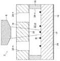
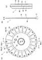
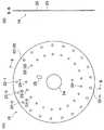
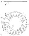
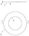
図1は、本実施例1の試液保持用ディスクを用いた光学式顕微鏡による細胞の計数観察装置の概略構成図、図2は、同ディスクの構成図であって、(A)は、その平面図、(B)は、(A)のB−B線断面図、(C)は、(B)のC部の拡大図、図3は、同ディスクの試液収納部を中心とする部分を説明するための概略拡大断面図、図4は、同ディスクに保護膜が貼着された状態を示す図2と略同様の図であって、(A)は、その平面図、(B)は、(A)のB−B線断面図、(C)は、(B)のC部の拡大図、図5は、同保護膜の構成図であって、(A)は、その平面図、(B)は、その側面図、図6は、同ディスクを構成する上部材の構成図であって、(A)は、その平面図、(B)は、(A)のB−B線断面図、図7は、同ディスクを構成する中間部材(センターフィルム)の構成図であって、(A)は、その平面図、(B)は、その側面図、図8は、同ディスクを構成する下部材の構成図であって、(A)は、その平面図、(B)は、(A)のB−B線断面図である。Next, an embodiment (Embodiment 1) of the present invention will be described.
FIG. 1 is a schematic configuration diagram of a cell counting and observing device using an optical microscope using the reagent solution holding disc of Example 1, FIG. 2 is a configuration diagram of the disc, and FIG. 4B is a cross-sectional view taken along the line BB of FIG. 3A, FIG. 3C is an enlarged view of a portion C of FIG. 3B, and FIG. 3 illustrates a portion centering on the reagent storage portion of the disk. 4 is a schematic enlarged cross-sectional view, FIG. 4 is a view substantially the same as FIG. 2 showing a state where a protective film is attached to the disk, (A) is a plan view thereof, (B) is (A) BB sectional drawing, (C) is an enlarged view of the C section of (B), FIG. 5 is the block diagram of the protective film, (A) is the top view, ( B) is a side view thereof, FIG. 6 is a block diagram of an upper member constituting the disk, (A) is a plan view thereof, and (B) is a sectional view taken along line BB of (A). Figure 7 shows the same disc It is a block diagram of the intermediate member (center film) to be formed, (A) is a plan view thereof, (B) is a side view thereof, and FIG. 8 is a block diagram of a lower member constituting the disk. (A) is the top view, (B) is the BB sectional drawing of (A).
図1に図示されるように、本実施例1の試液保持用ディスクを用いた光学式顕微鏡による細胞の計数観察装置1は、概略、細胞を含む試液を保持するためのディスク2と、該ディスク2を載置する載置台を有するターンテーブル3と、該ターンテーブル3及び該ディスク2を回転・位置決めするモータ4を含む回転・位置決め部5と、試液に光を照射する照明部6と、細胞を撮像(写真撮影)して、画像データとして出力する機能を備えた画像検出部をなすカメラ部7と、撮像した画像データを記憶する記憶部11と、画像データから細胞の数や状態を計数・観察する計数観察部12と、装置全体を制御する制御部13とを備えている。ターンテーブル3は、他の部分と並べて称すれば、ディスク2の「載置部」に相当するものである。記憶部11と、計数観察部12と、制御部13とは、パーソナルコンピュータ10の情報処理・操作部として、その内部に設けられている。パーソナルコンピュータ10は、他に表示部14、入力部15を備えている。 As shown in FIG. 1, a cell counting and
カメラ部7が取り付けられ、照明部6、対物レンズ8及び鏡筒部9を備えている光学系は、顕微鏡を構成しており、ディスク2の後述する試液収納部21−n内に収納された試液中の細胞が、照明部6から導かれた照明の下で、対物レンズ8を通して観察される。そして、観察されたその像は、カメラ部7で撮像される。実際には、照明部6から導かれた光が試液を透過して、ディスク2の後述する下部材17に設けられた反射面29により反射され、再び対物レンズ8を通ってカメラ部7へと導かれ、カメラ部7において受光しなかった影の部分が細胞の像として感知されるのである。このように、照明部6は、ディスク2に対して対物レンズ8と同じ側に配置されており、この光学式顕微鏡は、落射式顕微鏡として構成されている。このため、計数観察装置1の全高が低くなり、これを小型化することができる。 An optical system to which the
カメラ部7は、この細胞の像を撮像するとともに、画像データに変換して、これをパーソナルコンピュータ10の記憶部11に送信(出力)する。記憶部11に送られた細胞の画像データは、リアルタイムで、あるいは適時記憶部11から読み出されて、計数観察部12により、その数や状態が計数・観察される。その結果は、随時表示部14に表示されるとともに、記憶部11にも記憶される。 The
回転・位置決め部5を構成するモータ4は、ステッピングモータであり、所定時間間隔毎に所定角度回転して、ターンテーブル3を所定角度回転させ、同テーブルの載置台上に載置されたディスク2を同じ角度だけ回転させて、複数の試液収納部21−nのうちの1つを観察位置に位置決めする。計数観察装置1は、ディスク2が静止中の所定時間内に、観察位置に来た当該試液収納部21−n内に収納された試液中の細胞を計数・観察する。モータ4の回転制御は、パーソナルコンピュータ10の制御部13により行われる。 The
次に、ディスク2の構造について、図面を参照しながら、詳細に説明する。
ディスク2は、計数観察装置1が細胞を観察するのに便利なように、該細胞を含む試液を保持するために用いられ、図2に図示されるように、外観が薄い回転円盤状をなしている。そして、その外周部には、試液を保持するための複数(本実施例1においては、20個)の試液収納部21−n(n=1〜20)が円周方向に等間隔に放射状に並設されている。これら20個の試液収納部21−n(n=1〜20)は、モータ4の間歇回転により、ターンテーブル3及び該ターンテーブル3の載置台上に載置されたディスク2が間歇回転させられることにより、順次、計数観察装置1による観察位置にまで回転させられて、そこに位置決めされる。Next, the structure of the
The
ディスク2は、基本構造として、3枚の薄い板あるいはフィルム、すなわち、上部材16、中間部材(センターフィルム)18、下部材17の積層体として構成されている。
上部材16は、透明な樹脂材料から成り、観察時、対物レンズ8に面する側にあって、図2及び図6に図示されるように、薄い円板状をなし、その外周側に試液収納部21−n(n=1〜20)に試液を注入するための放射状に配置された複数の注入口22−n(n=1〜20)と、該注入口22−nと対をなす複数のエア抜き穴23−n(n=1〜20)とを有している。エア抜き穴23−nは、注入口21−nよりも内周側に形成されている。As a basic structure, the
The
また、上部材16は、位置決め穴24と位置決め穴25とを有している。位置決め穴24は、これら3枚の薄い板あるいはフィルムが積層されてディスク2として構成されたとき、このディスク2をターンテーブル3の載置台上でX−Y方向に位置決めして、その回転のための中心出しを行う。また、位置決め穴25は、平面視長円状をなし、このディスク2をターンテーブル3の載置台上で円周方向に位置決めして、その回転時の初期位置を定める。 Further, the
下部材17も、透明な樹脂材料から構成されており、観察時、ターンテーブル3の載置台に接する側にあって、図2及び図8に図示されるように、平面視ドーナツのような環状の薄い板状をなし、中央部に比較的大径の中央穴26を有している。下部材17の厚さは、上部材16の厚さと略同じにされている。 The
中間部材(センターフィルム)18も、樹脂材料から構成されるが、必ずしも透明な材料である必要はなく、図2及び図7に図示されるように、下部材17と同様に、平面視ドーナツのような環状の輪郭形状のきわめて薄いフィルム状をなし、中央部に比較的大径の中央穴27を有している。この中央穴27の径は、中央穴26の径と同じにされている。中間部材18の厚さは、上部材16及び下部材17の厚さの略1/5程度である。 The intermediate member (center film) 18 is also made of a resin material, but is not necessarily a transparent material. As shown in FIG. 2 and FIG. An extremely thin film shape having such an annular contour shape is formed, and a
中間部材18の外周縁と中央穴27との間には、試液をフィルムの面方向において保持するための複数(本実施例1においては、20個)のルーム28−n(n=1〜20)が円周方向に等間隔に放射状に並設されている。このルーム28−nの平面形状は、中間部材18の中心側が小さくされ、4つの角部が丸められた略二等辺台形状をなしている。 Between the outer peripheral edge of the
中間部材18は、上部材16から押さえられ、下部材17により受けられて、これらによりサンドイッチ状に挟まれ、これらと接着させられる。そして、全体が一体の積層構造体となって、ディスク2の骨格構造を形成している。この結果、中間部材18のルーム28−nは、これら上部材16と下部材17とにより封止されて、そこに、前記した試液収納部21−n(n=1〜20)が形成されている。この試液収納部21−nは、試液を収納・保持するための偏平な閉鎖室であって、上部材16に形成された注入口22−nとエア抜き穴23−nとを介してのみ外部と連通している。試液収納部21−nを中心とし、これを取り巻く部分の構造が図3に拡大図示されている。図3は、その部分の構造を分かり易くするために模式的に描かれており、正確な縮尺に従っていない。符号35は、細胞を示す。 The
なお、ディスク2の上部材16、中間部材18及び下部材17の相互間の接着は、実際には、中間部材18が精密に厚みを制御された、厚みが一定の両面接着剤付きフィルムとして構成されており、この両面の接着剤が利用されることにより行われている。中間部材18がこのようなフィルムとして構成されることにより、これら3つの部材が互いに接着させられて全体が一体の積層構造体となったとき、その内部には、高い寸法精度の試液収納部21−nが形成されることになる。 The bonding between the
ディスク2を構成する上部材16、中間部材18及び下部材17は、いずれも使い捨て可能な樹脂材料を用いて製作されており、これにより、細胞の計数・観察の作業効率が格段に向上する。また、公害を生じることもない。さらに、これらの部材は、それぞれの材料を打ち抜きした部品から構成されているので、その製作が、成形加工による場合に比べて、きわめて容易である。 The
ディスク2を構成する下部材17のターンテーブル3の載置台と接する側の面、換言すれば、上部材16と対向する側と反対側の面は、図2及び図3に図示されるように、反射面29とされている。この反射面29は、下部材17の同面に、スパッタリング等の方法により、アルミニウムもしくは銀又はその他の金属蒸着膜19を形成することにより得られる。なお、この反射面29は、下部材17の上部材16と対向する側の面に形成されても良く、また、ターンテーブル3のディスク載置台面(但し、このディスク載置台面は、ディスク2の外径と略同程度に拡径されている。)に形成されても良い。 As shown in FIGS. 2 and 3, the surface of the
ディスク2を構成する上部材16の下部材17と対向する側の面には、図2及び図3に図示されるように、親水性膜20が蒸着されている。この親水性膜20は、上部材16の同面に、スパッタリング等の方法により、酸化珪素SiO2の蒸着膜を形成することにより得られる。なお、この親水性膜20は、下部材17の上部材16と対向する側の面に蒸着されても良いし、上部材16と下部材17の双方の、それらが対向する側の面に蒸着されても良い。この親水性膜20は、上部材16の注入口22−nから注入された試液を、表面張力に抗して試液収納部21−n内に均一に分布させて、そこに確実且つ安定に保持させるのに役立つ。 As shown in FIGS. 2 and 3, a
なお、ディスク2を構成する上部材16の外表面には、図4に図示されるように、保護膜30が貼着されている。この保護膜30は、中間部材18が有する複数のルーム28−n(n=1〜20)の個々のルーム28−n毎に、換言すれば、ディスク2の複数の試液収納部21−n(n=1〜20)の個々の試液収納部21−n毎に、同図の円32及び線分33の個所で個別に剥がして取り去ることができるようにされており、ディスク2を実際に使用するに際しては、必要個所のみ、そこに貼着されている保護膜片30a−n(n=1〜20)を剥がして、そこに顕れた試液収納部21−nを細胞の計数観察のために使用することができる。 A
保護膜30の中央部には、比較的小径の中央穴31が形成されている。この中央穴31の径は、上部材16の位置決め穴24の径よりわずかに大きくされている。また、この中央穴31よりやや外方にずれた位置には、平面視長円状の逃がし穴34が形成されている。この逃がし穴34は、上部材16が有する位置決め穴25よりわずかに大きくされている。各保護膜片30a−nには、試液収納部21−n(n=1〜20)の番号01〜20が記され、中央穴31の周囲には、製作会社名及び品名を示す文字が記されている。なお、図5には、保護膜30の単品が図示されている。 A
本実施例1のディスク2及び計数観察装置1を用いて細胞を計数・観察するには、先ず、試料数に合わせて、ディスク2の複数の試液収納部21−n(n=1〜20)のうちの所要数の試液収納部21−nの各上部を覆う保護膜片30a−nを剥がし、上部材16の注入口22−nから当該試液収納部21−n内に試液を注入する。次いで、ディスク2をターンテーブル3の載置台上に移して、モータ4を間歇回転させ、これにより、ターンテーブル3及びディスク2を間歇回転させて、所要数の試液収納部21−nを、順次、計数観察装置1による観察位置にまで回転移動させ、そこに位置決めする。そして、観察位置に位置決めされた所定の試液収納部21−n内に収納・保持された試液中の細胞を、計数観察装置1により計数・観察する。 In order to count and observe cells using the
観察位置に位置決めされた所定の試液収納部21−n内に収納・保持された試液中の細胞を、計数観察装置1により計数・観察するのには、実際には、次のようにして行われる。すなわち、試液収納部21−nの全領域(換言すれば、ルーム28−nの全領域)を、一度に、計数観察装置1により撮像するのではなく、この試液収納部21−nを、図9に図示されるように、複数の視野36−n(n=1〜8)に分割し、隣接する視野36−nと36−(n+1)との間隔を1ピッチとして、ディスク2をモータ4によりさらに細かく間歇回転させて、各視野毎に計数観察装置1により写真を撮影して行き、その画像データから、例えば、細胞数を計測し、それらの平均値により細胞濃度を決定するものである。このようにすることにより、偏りがなく、正確な計数観察を行うことができる。各視野36−nの大きさは、0.5mm2(0.7×0.7mm)程度である。なお、8個の視野36−nの全てを計数・観察するのに限られず、必要に応じ、1〜8個の視野36−nを選択して計数・観察することができる。また、視野36−nの総数は、8個に限定されない。In order to count and observe the cells in the test solution stored and held in the predetermined test solution storage unit 21-n positioned at the observation position by the
本実施例1の試液保持用のディスク2及び該ディスク2を用いた光学式顕微鏡による細胞の計数観察装置1は、前記のように構成されているので、次のような効果を奏することができる。
細胞を含む試液を保持するためのディスク2が、上部材16と中間部材18と下部材17との3層の積層構造からなっているので、ディスク2の製作が容易である。しかも、試液収納部21−nの寸法は、中間部材18が有する、試液を保持するための放射状に配置された複数のルーム28−nの個々のルーム28−nの寸法により定まるので、試液収納部21−nの寸法、特に深さ寸法を高精度に仕上げるのが容易になる。これらにより、高精度のディスク2を容易に、低コストで製作することができる。Since the
Since the
また、ディスク2は、使い捨て可能な材料を用いて製作されているので、細胞の計数観察の効率性を格段に向上させることができる。また、公害を生ずることもない。 Further, since the
また、ディスク2を構成する上部材16、中間部材18及び下部材17は、それぞれの材料を打ち抜きした部品から構成されており、かつ、これらの部材は、中間部材18が精密に厚みを制御された、厚みが一定の両面接着剤付きフィルムとして構成され、この両面の接着剤が利用されることにより互いに接着されているので、高精度なディスクをさらに容易に、さらに低コストで製作することができる。 Further, the
さらに、ディスク2を構成する下部材17の上部材16と対向する側の面もしくはそれと反対側の面は、反射面29とされているので、そのディスク2が落射式顕微鏡を用いた細胞の計数観察装置1に用いられる場合に、その反射面29を照射光の反射面として利用することができ、落射式顕微鏡の構成が容易になる。なお、ターンテーブル3のディスク載置台面が反射面とされる場合にも、同様の効果を奏することができる。 Further, since the surface on the side facing the
また、ディスク2を構成する上部材16と下部材17とのいずれかもしくは双方には、それらが対向する側の面に親水性膜20が蒸着されているので、上部材16の注入口22−nから注入された試液を試液収納部21−n内に均一に分布させて、そこに確実且つ安定に保持させることができる。 Further, since a
また、ディスク2を構成する上部材16の外表面には、個々のルーム28−n毎に個別に剥がして取り去ることができる保護膜30が貼着されているので、ディスク2を実際に使用するに際しては、当座の細胞の計数観察に必要な個所のみ、そこに貼着されている保護膜片30a−nを剥がして、そこに顕れたルームルーム28−n及び試液収納部21−nを細胞の計数観察のために使用することができ、残りの個所のルーム28−m及び試液収納部21−m(m≠n、m、n=1〜20)は、それらの上部が保護膜片30a−m(m≠n、m、n=1〜20)で覆われたままの状態にしておいて、後で使用するときに、そこがゴミや埃に遮られて計数観察しにくくなるのを防ぐことができる。Moreover, since the
さらに、ディスク2を用いた光学式顕微鏡による細胞の計数観察装置1は、高精度で、製作が容易で、低コストなディスク2を用いて、信頼性が高く、偏りがなく正確で、効率的な自動計数観察が可能で、低コストなものとすることができ、また、その光学式顕微鏡は、落射式顕微鏡として構成することができるので、計数観察装置1を小型化することができる。 Furthermore, the cell counting and
次に、本願の発明の他の実施例(実施例2)について説明する。
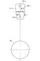
図10は、本実施例2の試液保持用ディスクを用いた光学式顕微鏡による細胞の計数観察装置の概略構成図、図11は、同光学式顕微鏡による細胞の計数観察装置において、その載置部にディスクを載置した状態を示す図10と同様の図である。なお、実施例1の同様の計数観察装置の各部分と対応する部分には、同一の符号を付している。Next, another embodiment (embodiment 2) of the present invention will be described.
FIG. 10 is a schematic configuration diagram of a cell counting and observing device using an optical microscope using the reagent solution holding disk of Example 2, and FIG. 11 is a diagram illustrating a mounting portion of the cell counting and observing device using the optical microscope. FIG. 11 is a view similar to FIG. In addition, the same code | symbol is attached | subjected to the part corresponding to each part of the same count observation apparatus of Example 1. FIG.
本実施例2の試液保持用ディスクを用いた光学式顕微鏡による細胞の計数観察装置41は、図10に図示されるように、実施例1の同様の計数観察装置1と比較すると、ディスク2の載置部43の構造のみが異なっている。
すなわち、その載置部43は、固定テーブル44の上面44aに、ディスク2を支持するための円周方向に等しい間隔を置いて配置された3つの支持体(ピン)45を備えており、そのうちの1つの支持体45は、画像検出部(カメラ部)7が備える対物レンズ8の直下に位置していて、これらの間に一定の距離dが保持されている。なお、支持体45の数は、3つに限られず、それより多くされても良い。また、ここで言われる「対物レンズ8の直下」とは、正確に対物レンズ8の直下である必要はなく、その近傍であれば良い。As shown in FIG. 10, the cell
That is, the mounting
固定テーブル44の中心部の円筒状空洞内には、回転テーブル46が同心に挿入されて、そこに回転可能に支持されている。この回転テーブル46は、図示されないが、固定テーブル44の下方において、モータ4の出力端と伝動ベルト37を介して連結されており、このモータ4により、間歇回転駆動される。 A rotary table 46 is inserted concentrically into a cylindrical cavity at the center of the fixed table 44 and is rotatably supported therein. Although not shown, the rotary table 46 is connected to the output end of the
回転テーブル46の上面46aの中心部には、短い円柱状突起47が突出形成されており、また、それと所定の距離を置いて、上面46aの外周縁寄りの1個所には、ピン状突起48が突出形成されている。円柱状突起47の外径は、上部材16の位置決め穴24の直径と略等しく、ピン状突起48の外径は、上部材16の位置決め穴25の幅と略等しい。 A
ディスク2は、載置部43の上に、次のようにして載置される。
すなわち、ディスク2は、載置部43の回転テーブル46の上面46aに突出形成された円柱状突起47にその位置決め穴24が嵌合させられ、また、同じくピン状突起48にその位置決め穴25が通された状態で、3つの支持体45の上面45a上に載置される。この時、ディスク2の裏面は、上面46aに接触してはおらず、これらの間には、適宜の間隔が設けられている。このようにして、円柱状突起47に位置決め穴24が嵌合させられることにより、ディスク2の回転のための中心出しが行われる。また、ピン状突起48に位置決め穴25が通されることにより、ディスク2の回転時の初期位置を定めることが可能になる。The
That is, the
そこで、今、モータ4が作動を開始して、回転テーブル46が間歇回転駆動されると、ディスク2は、円柱状突起47の中心軸上に回転中心を定めつつ、ピン状突起48により円周方向に引っ張られて、3つの支持体45の上面45a上を滑りながら、間歇回転する。先ず、隣接する試液収納部21−nと試液収納部21−(n+1)との間隔を1ピッチとして、1回回転する。次いで、隣接する視野36−nと視野36−(n+1)との間隔を1ピッチとして、8回間歇回転する。この8回の間歇回転の間に、各視野の写真が撮影される。そして、このような間歇回転パターンが、試液収納部21−nの数だけ(本実施例2の場合、20回)繰り返されるものである。 Therefore, when the
なお、3つの支持体45のうち、対物レンズ8の直下に位置させられる支持体45の上面45aが反射面に構成されると、好都合である。そのように構成されると、ディスク2を構成する下部材17の表裏何れかの面を反射面29にする必要がなくなる。 Of the three
本実施例2の試液保持用のディスク2を用いた光学式顕微鏡による細胞の計数観察装置41は、前記のように構成されているので、次のような効果を奏することができる。
ディスク2は、3つ又はそれ以上の複数の支持体45により支持・載置され、これら支持体45の支持面45a上を滑りながら回転することになり、ディスク2の回転駆動系の動揺、例えば、波打ち現象等の不安定要素を排除することができ、また、観察位置では、ディスク2は対物レンズ8直下又はその近傍の支持体45により支持され、対物レンズ8と一定の距離が保持されるので、より正確な自動計数観察が可能になる。Since the cell counting / observing
The
また、対物レンズ8の直下に位置する支持体45の支持面45aが反射面とされる場合には、載置部43のディスク2を載置する側の面を反射面とするための蒸着のコストを大幅に低減することができ、より低コストな光学式顕微鏡による細胞の計数観察装置を提供することができる。また、蒸着に代えて、鏡面体が該支持体45に付設される場合には、蒸着のコストを不要にすることができ、蒸着による品質不良の可能性もなくすることができる。 Further, when the
なお、本願の発明は、以上の実施例に限定されず、その要旨を逸脱しない範囲において、種々の変形が可能である。 The invention of the present application is not limited to the above embodiments, and various modifications can be made without departing from the scope of the invention.
1…細胞の計数観察装置、2…ディスク、3…ターンテーブル(載置部)、4…モータ、5…回転・位置決め部、6…照明部、7…カメラ部(画像検出部)、8…対物レンズ、9…鏡筒部、10…パーソナルコンピュータ、11…記憶部、12…計数観察部、13…制御部、14…表示部、15…入力部、16…上部材、17…下部材、18…中間部材(センターフィルム)、19…金属蒸着膜、20…親水性膜、21−n(n=1〜20)…試液収納部、22−n(n=1〜20)…注入口、23−n(n=1〜20)…エア抜き穴、24、25…位置決め穴、26、27…中央穴、28−n(n=1〜20)…ルーム、29…反射面、30…保護膜、30a−n(n=1〜20)…保護膜片、31…中央穴、32…円、33…線分、34…逃がし穴、35…細胞、36−n(n=1〜8)…視野、37…伝動ベルト、41…細胞の計数観察装置、43…載置部、44…固定テーブル、44a…上面、45…支持体(ピン)、45a…上面、46…回転テーブル、46a…上面、47…円柱状突起、48…ピン状突起。
DESCRIPTION OF
Claims (12)
Translated fromJapanese前記試液を注入するための放射状に配置された複数の注入口と、前記注入口と対をなす複数のエア抜き穴とを有する透明な材料からなる上部材と、
前記試液を保持するための放射状に配置された複数のルームであって、各一対の前記注入口と前記エア抜き穴とに対応して、これらに連通するようにして設けられた複数のルーム、を有する中間部材と、
前記中間部材を受ける透明な材料からなる下部材と、
を備え、
前記上部材及び前記下部材と前記複数のルームとで囲まれた空間により複数の試液収納部を形成し、
前記上部材の前記下部材と対向する側の面に、透明なSiO2からなる親水性膜を設け、
前記親水性膜により、前記注入口から前記試液収納部内に注入された前記試液を、表面張力に抗して試液収納部内に均一に分布させる
ことを特徴とするディスク。A disk used to count cells with an optical microscope and hold a test solution containing cells.
An upper member made of a transparent material having a plurality of radially arranged inlets for injecting the reagent solution and a plurality of air vent holes paired with the inlet;
A plurality of rooms arranged radially to hold the reagent solution, corresponding to each pair of the inlet and the air vent hole, a plurality of rooms provided to communicate with these, An intermediate member having
A lower member made of a transparent material for receiving the intermediate member;
With
A plurality of reagent storage parts are formed by a space surrounded by the upper member and the lower member and the plurality of rooms,
A hydrophilic film made of transparent SiO2 is provided on the surface of the upper member facing the lower member,
The disk, wherein the hydrophilic film distributes the test solution injected from the injection port into the test solution storage unit uniformly in the test solution storage unit against surface tension .
前記上部材、前記中間部材及び前記下部材は、前記フィルムの両面に付された接着剤により互いに接着されている
ことを特徴とする請求項5に記載のディスク。Before Symbol intermediate member is configured as with the film constant sided adhesive thickness,
6. The disk according to claim5 , wherein the upper member, the intermediate member, and the lower member are bonded to each other by an adhesive applied to both surfaces of the film.
前記ディスクを載置する載置部と、
前記ディスクを回転・位置決めする回転・位置決め部と、
前記試液に光を照射する照明部と、
前記細胞を撮像して、画像データとして出力する機能を備えた画像検出部と、
前記撮像した画像データを記憶する記憶部と、
前記画像データから前記細胞の数や状態を計数・観察する計数観察部と、
装置全体を制御する制御部と
を備え、
前記記憶部と、前記計数観察部と、前記制御部とは、パーソナルコンピュータの情報処理・操作部として、その内部に設けられており、
前記ルームを複数の視野に分割し、各視野毎に前記細胞を撮像して、その画像データから細胞数を計測し、それらの平均値により細胞濃度を決定することが可能なようにされている
ことを特徴とする光学式顕微鏡による細胞の計数観察装置。A disk according to any one of claims 1 to7 ,
A mounting section for mounting the disc;
A rotation / positioning unit for rotating / positioning the disk;
An illumination unit for irradiating the test solution with light;
An image detection unit having a function of imaging the cell and outputting the image data;
A storage unit for storing the captured image data;
A counting observation unit for counting and observing the number and state of the cells from the image data;
A control unit for controlling the entire apparatus,
The storage unit, the counting observation unit, and the control unit are provided as an information processing / operation unit of a personal computer,
The room is divided into a plurality of visual fields, the cells are imaged for each visual field, the number of cells is measured from the image data, and the cell concentration can be determined by the average value thereof. An apparatus for counting and observing cells using an optical microscope.
複数の前記支持体のうちの1つは、前記画像検出部が備える対物レンズの直下又はその近傍に位置していて、これらの間に一定の距離が保持されている
ことを特徴とする請求項8に記載の光学式顕微鏡による細胞の計数観察装置。The mounting section includes a plurality of support bodies of three or more arranged at appropriate intervals in the circumferential direction to support the disk,
The one of the plurality of supports is located immediately below or in the vicinity of an objective lens included in the image detection unit, and a certain distance is maintained between them. 9. A cell count observation apparatus using the optical microscope according to8 .
前記ディスクを載置する載置部と、
前記ディスクを回転・位置決めする回転・位置決め部と、
前記試液に光を照射する照明部と、
前記細胞を撮像して、画像データとして出力する機能を備えた画像検出部と、
前記撮像した画像データを記憶する記憶部と、
前記画像データから前記細胞の数や状態を計数・観察する計数観察部と、
装置全体を制御する制御部と
を備え、
前記記憶部と、前記計数観察部と、前記制御部とは、パーソナルコンピュータの情報処理・操作部として、その内部に設けられており、
前記ルームを複数の視野に分割し、各視野毎に前記細胞を撮像して、その画像データから細胞数を計測し、それらの平均値により細胞濃度を決定することが可能なようにされている光学式顕微鏡による細胞の計数観察装置であって、
前記載置部の前記ディスクを載置する側の面は、反射面とされていることを特徴とする光学式顕微鏡による細胞の計数観察装置。A disk according to any oneof claims 1, 2, 5 to7 ,
A mounting section for mounting the disc;
A rotation / positioning unit for rotating / positioning the disk;
An illumination unit for irradiating the test solution with light;
An image detection unit having a function of imaging the cell and outputting the image data;
A storage unit for storing the captured image data;
A counting observation unit for counting and observing the number and state of the cells from the image data;
A control unit for controlling the entire apparatus,
The storage unit, the counting observation unit, and the control unit are provided as an information processing / operation unit of a personal computer,
The room is divided into a plurality of visual fields, the cells are imaged for each visual field, the number of cells is measured from the image data, and the cell concentration can be determined by an average value thereof. An apparatus for counting and observing cells with an optical microscope,
An apparatus for counting and observing cells with an optical microscope, wherein the surface of the mounting portion on which the disk is placed is a reflective surface.
複数の前記支持体のうちの1つは、前記画像検出部が備える対物レンズの直下又はその近傍に位置していて、これらの間に一定の距離が保持されている
ことを特徴とする請求項10に記載の光学式顕微鏡による細胞の計数観察装置。The mounting section includes a plurality of support bodies of three or more arranged at appropriate intervals in the circumferential direction to support the disk,
The one of the plurality of supports is located immediately below or in the vicinity of an objective lens included in the image detection unit, and a certain distance is maintained between them.10. An apparatus for counting and observing cells with the optical microscope according to10 .
Priority Applications (4)
| Application Number | Priority Date | Filing Date | Title |
|---|---|---|---|
| JP2005269818AJP4664785B2 (en) | 2005-09-16 | 2005-09-16 | Disc and cell counting and observation apparatus using optical disc using optical disc |
| EP06011549AEP1764410B1 (en) | 2005-09-16 | 2006-06-02 | Disk and cell counting and observation apparatus |
| DE602006002457TDE602006002457D1 (en) | 2005-09-16 | 2006-06-02 | Bio-disk and device for the determination and observation of cells |
| US11/448,878US8568660B2 (en) | 2005-09-16 | 2006-06-08 | Disk, and counting observation apparatus for counting and observing cells through optical microscope by use of the disk |
Applications Claiming Priority (1)
| Application Number | Priority Date | Filing Date | Title |
|---|---|---|---|
| JP2005269818AJP4664785B2 (en) | 2005-09-16 | 2005-09-16 | Disc and cell counting and observation apparatus using optical disc using optical disc |
Publications (2)
| Publication Number | Publication Date |
|---|---|
| JP2007078614A JP2007078614A (en) | 2007-03-29 |
| JP4664785B2true JP4664785B2 (en) | 2011-04-06 |
Family
ID=37333745
Family Applications (1)
| Application Number | Title | Priority Date | Filing Date |
|---|---|---|---|
| JP2005269818AExpired - Fee RelatedJP4664785B2 (en) | 2005-09-16 | 2005-09-16 | Disc and cell counting and observation apparatus using optical disc using optical disc |
Country Status (4)
| Country | Link |
|---|---|
| US (1) | US8568660B2 (en) |
| EP (1) | EP1764410B1 (en) |
| JP (1) | JP4664785B2 (en) |
| DE (1) | DE602006002457D1 (en) |
Families Citing this family (8)
| Publication number | Priority date | Publication date | Assignee | Title |
|---|---|---|---|---|
| ITBO20070646A1 (en)* | 2007-09-24 | 2009-03-25 | Silicon Biosystems Spa | CHAMBER OF COUNTING FOR SAMPLES ANALYSIS |
| US9354155B2 (en) | 2011-05-31 | 2016-05-31 | Bio-Rad Laboratories, Inc. | Cell counting systems and methods |
| CN102358466A (en)* | 2011-06-21 | 2012-02-22 | 山东大学 | Disk-type sample storage unit |
| WO2016121065A1 (en) | 2015-01-29 | 2016-08-04 | オリンパス株式会社 | Device and method for analyzing cell |
| WO2016162945A1 (en) | 2015-04-07 | 2016-10-13 | オリンパス株式会社 | Cell analysis device and cell analysis method |
| CN109061214B (en)* | 2018-10-31 | 2023-12-19 | 江苏卓微生物科技有限公司 | Porous sample injection device |
| DE102023101475A1 (en)* | 2023-01-20 | 2024-07-25 | Testo bioAnalytics GmbH | Method and measuring channel for optical recording of microparticles in a particle stream |
| DE102023101480A1 (en)* | 2023-01-20 | 2024-07-25 | Testo bioAnalytics GmbH | Method and detection area for recording microparticles and disc-shaped sample carrier |
Family Cites Families (18)
| Publication number | Priority date | Publication date | Assignee | Title |
|---|---|---|---|---|
| JPS62262814A (en)* | 1986-05-09 | 1987-11-14 | Shimadzu Corp | Reflective optical observation device |
| JPS63131116A (en)* | 1986-11-21 | 1988-06-03 | Hitachi Ltd | confocal microscope |
| IL98150A0 (en)* | 1990-05-17 | 1992-08-18 | Adeza Biomedical Corp | Highly reflective biogratings and method for theirhighly reflective biogratings and method production |
| JPH0882590A (en)* | 1994-09-12 | 1996-03-26 | Hideki Yamaguchi | Sample cell holding member |
| JP3434064B2 (en) | 1995-01-20 | 2003-08-04 | 三菱重工業株式会社 | Epi-illumination phase contrast microscope |
| US5545438A (en)* | 1995-03-22 | 1996-08-13 | Betz Laboratories, Inc. | Hydrophilic treatment for aluminum |
| US5983120A (en)* | 1995-10-23 | 1999-11-09 | Cytometrics, Inc. | Method and apparatus for reflected imaging analysis |
| CA2239613A1 (en)* | 1995-12-05 | 1997-06-12 | Alec Mian | Devices and methods for using centripetal acceleration to drive fluid movement in a microfluidics system with on-board informatics |
| EP1021708A1 (en)* | 1996-11-11 | 2000-07-26 | Novartis AG | Use of biosensors to diagnose plant diseases |
| JPH1123569A (en)* | 1997-07-08 | 1999-01-29 | Suzuki Motor Corp | Plate protection seal and plate protection plate |
| JP2000292422A (en)* | 1999-04-02 | 2000-10-20 | Olympus Optical Co Ltd | Scanning site meter |
| US6937323B2 (en)* | 2000-11-08 | 2005-08-30 | Burstein Technologies, Inc. | Interactive system for analyzing biological samples and processing related information and the use thereof |
| WO2003036337A2 (en)* | 2001-10-24 | 2003-05-01 | Burstein Technologies, Inc. | Optical biological disk analyser |
| CN1636141A (en)* | 2001-10-24 | 2005-07-06 | 长冈实业株式会社 | Segmented Region Detectors and Related Methods for Biological Actuators |
| WO2003044481A2 (en)* | 2001-11-20 | 2003-05-30 | Burstein Technologies, Inc. | Optical bio-discs and microfluidic devices for analysis of cells |
| JP4434649B2 (en)* | 2003-03-27 | 2010-03-17 | 株式会社Eci | Observation instrument and observation method using the same |
| WO2004095034A1 (en)* | 2003-04-23 | 2004-11-04 | Nagaoka & Co., Ltd. | Optical bio-discs including spiral fluidic circuits for performing assays |
| ATE385572T1 (en)* | 2004-03-05 | 2008-02-15 | Egomedical Swiss Ag | ANALYTE TEST SYSTEM FOR DETERMINING THE CONCENTRATION OF AN ANALYTE IN A PHYSIOLOGICAL LIQUID |
- 2005
- 2005-09-16JPJP2005269818Apatent/JP4664785B2/ennot_activeExpired - Fee Related
- 2006
- 2006-06-02DEDE602006002457Tpatent/DE602006002457D1/enactiveActive
- 2006-06-02EPEP06011549Apatent/EP1764410B1/ennot_activeNot-in-force
- 2006-06-08USUS11/448,878patent/US8568660B2/ennot_activeExpired - Fee Related
Also Published As
| Publication number | Publication date |
|---|---|
| US20070063142A1 (en) | 2007-03-22 |
| JP2007078614A (en) | 2007-03-29 |
| EP1764410B1 (en) | 2008-08-27 |
| US8568660B2 (en) | 2013-10-29 |
| DE602006002457D1 (en) | 2008-10-09 |
| EP1764410A1 (en) | 2007-03-21 |
Similar Documents
| Publication | Publication Date | Title |
|---|---|---|
| EP1764410B1 (en) | Disk and cell counting and observation apparatus | |
| CA2772376C (en) | Compact automated cell counter | |
| EP1742064B1 (en) | Methods and apparatus for imaging and processing of samples in biological sample containers | |
| US6414805B1 (en) | Reflected-light type fluorescence microscope and filter cassette used therefor | |
| EP2924706B1 (en) | Sample stage, charged particle beam device and sample observation method | |
| JPH0278959A (en) | Analyzer with reaction cartridge | |
| TW200931060A (en) | Microscope calibration apparatus and method and stage including calibration apparatus | |
| ES2868142T3 (en) | Test platform, test apparatus and control method thereof | |
| ITUB20155205A1 (en) | OPTICAL ADAPTER CAN BE CONNECTED WITH AN IMAGE ACQUISITION DEVICE AND IN PARTICULAR INTENDED FOR USE IN MICROSCOPIC OBSERVATION. | |
| WO2022149162A1 (en) | A compact portable multimodal microscopy | |
| WO2019240959A1 (en) | Device and method of imaging fluidic samples | |
| CN214154645U (en) | Shooting equipment and microscope | |
| WO2025027299A2 (en) | Microscope apparatus | |
| TWI775355B (en) | Observation holder, observation device, observation wafer, and manufacturing method thereof | |
| JP2000314696A (en) | Plate for observing sample and observing apparatus | |
| JPH10239507A (en) | Optical image forming device | |
| JP2017003330A (en) | Sealing sheet, inspection kit and mounting method | |
| JP2002098623A (en) | Image pickup device for micro-object | |
| Agroskin et al. | Luminescence video analyzer of biological microchips | |
| JPH0998948A (en) | Visual function test device | |
| JPH05107400A (en) | Sample holder for X-ray microscope with easy alignment | |
| JPH09297093A (en) | Sample cell for x-ray microscope | |
| JP2006349584A (en) | Otf (optical transfer function) measuring instrument | |
| TW200417727A (en) | Disc-shaped biological chip detection system and its detecting method | |
| JP2001091418A (en) | Sample for lcm |
Legal Events
| Date | Code | Title | Description |
|---|---|---|---|
| A621 | Written request for application examination | Free format text:JAPANESE INTERMEDIATE CODE: A621 Effective date:20080507 | |
| A977 | Report on retrieval | Free format text:JAPANESE INTERMEDIATE CODE: A971007 Effective date:20100630 | |
| A131 | Notification of reasons for refusal | Free format text:JAPANESE INTERMEDIATE CODE: A131 Effective date:20100709 | |
| A521 | Request for written amendment filed | Free format text:JAPANESE INTERMEDIATE CODE: A523 Effective date:20100907 | |
| TRDD | Decision of grant or rejection written | ||
| A01 | Written decision to grant a patent or to grant a registration (utility model) | Free format text:JAPANESE INTERMEDIATE CODE: A01 Effective date:20110104 | |
| A01 | Written decision to grant a patent or to grant a registration (utility model) | Free format text:JAPANESE INTERMEDIATE CODE: A01 | |
| A61 | First payment of annual fees (during grant procedure) | Free format text:JAPANESE INTERMEDIATE CODE: A61 Effective date:20110107 | |
| R150 | Certificate of patent or registration of utility model | Free format text:JAPANESE INTERMEDIATE CODE: R150 | |
| FPAY | Renewal fee payment (event date is renewal date of database) | Free format text:PAYMENT UNTIL: 20140114 Year of fee payment:3 | |
| FPAY | Renewal fee payment (event date is renewal date of database) | Free format text:PAYMENT UNTIL: 20140114 Year of fee payment:3 | |
| S111 | Request for change of ownership or part of ownership | Free format text:JAPANESE INTERMEDIATE CODE: R313117 | |
| FPAY | Renewal fee payment (event date is renewal date of database) | Free format text:PAYMENT UNTIL: 20140114 Year of fee payment:3 | |
| R350 | Written notification of registration of transfer | Free format text:JAPANESE INTERMEDIATE CODE: R350 | |
| R250 | Receipt of annual fees | Free format text:JAPANESE INTERMEDIATE CODE: R250 | |
| LAPS | Cancellation because of no payment of annual fees |