JP4664662B2 - Signal or lighting equipment for automobiles - Google Patents
Signal or lighting equipment for automobilesDownload PDFInfo
- Publication number
- JP4664662B2 JP4664662B2JP2004364197AJP2004364197AJP4664662B2JP 4664662 B2JP4664662 B2JP 4664662B2JP 2004364197 AJP2004364197 AJP 2004364197AJP 2004364197 AJP2004364197 AJP 2004364197AJP 4664662 B2JP4664662 B2JP 4664662B2
- Authority
- JP
- Japan
- Prior art keywords
- light
- signal
- light guide
- function
- light source
- Prior art date
- Legal status (The legal status is an assumption and is not a legal conclusion. Google has not performed a legal analysis and makes no representation as to the accuracy of the status listed.)
- Expired - Fee Related
Links
Images


Classifications
- G—PHYSICS
- G02—OPTICS
- G02B—OPTICAL ELEMENTS, SYSTEMS OR APPARATUS
- G02B6/00—Light guides; Structural details of arrangements comprising light guides and other optical elements, e.g. couplings
- G02B6/0001—Light guides; Structural details of arrangements comprising light guides and other optical elements, e.g. couplings specially adapted for lighting devices or systems
- G02B6/0005—Light guides; Structural details of arrangements comprising light guides and other optical elements, e.g. couplings specially adapted for lighting devices or systems the light guides being of the fibre type
- G02B6/0006—Coupling light into the fibre
- B—PERFORMING OPERATIONS; TRANSPORTING
- B60—VEHICLES IN GENERAL
- B60Q—ARRANGEMENT OF SIGNALLING OR LIGHTING DEVICES, THE MOUNTING OR SUPPORTING THEREOF OR CIRCUITS THEREFOR, FOR VEHICLES IN GENERAL
- B60Q1/00—Arrangement of optical signalling or lighting devices, the mounting or supporting thereof or circuits therefor
- B60Q1/26—Arrangement of optical signalling or lighting devices, the mounting or supporting thereof or circuits therefor the devices being primarily intended to indicate the vehicle, or parts thereof, or to give signals, to other traffic
- B60Q1/2696—Mounting of devices using LEDs
- B—PERFORMING OPERATIONS; TRANSPORTING
- B60—VEHICLES IN GENERAL
- B60Q—ARRANGEMENT OF SIGNALLING OR LIGHTING DEVICES, THE MOUNTING OR SUPPORTING THEREOF OR CIRCUITS THEREFOR, FOR VEHICLES IN GENERAL
- B60Q1/00—Arrangement of optical signalling or lighting devices, the mounting or supporting thereof or circuits therefor
- B60Q1/26—Arrangement of optical signalling or lighting devices, the mounting or supporting thereof or circuits therefor the devices being primarily intended to indicate the vehicle, or parts thereof, or to give signals, to other traffic
- B60Q1/30—Arrangement of optical signalling or lighting devices, the mounting or supporting thereof or circuits therefor the devices being primarily intended to indicate the vehicle, or parts thereof, or to give signals, to other traffic for indicating rear of vehicle, e.g. by means of reflecting surfaces
- B60Q1/302—Arrangement of optical signalling or lighting devices, the mounting or supporting thereof or circuits therefor the devices being primarily intended to indicate the vehicle, or parts thereof, or to give signals, to other traffic for indicating rear of vehicle, e.g. by means of reflecting surfaces mounted in the vicinity, e.g. in the middle, of a rear window
- B—PERFORMING OPERATIONS; TRANSPORTING
- B60—VEHICLES IN GENERAL
- B60Q—ARRANGEMENT OF SIGNALLING OR LIGHTING DEVICES, THE MOUNTING OR SUPPORTING THEREOF OR CIRCUITS THEREFOR, FOR VEHICLES IN GENERAL
- B60Q3/00—Arrangement of lighting devices for vehicle interiors; Lighting devices specially adapted for vehicle interiors
- B60Q3/60—Arrangement of lighting devices for vehicle interiors; Lighting devices specially adapted for vehicle interiors characterised by optical aspects
- B60Q3/62—Arrangement of lighting devices for vehicle interiors; Lighting devices specially adapted for vehicle interiors characterised by optical aspects using light guides
- B60Q3/64—Arrangement of lighting devices for vehicle interiors; Lighting devices specially adapted for vehicle interiors characterised by optical aspects using light guides for a single lighting device
- F—MECHANICAL ENGINEERING; LIGHTING; HEATING; WEAPONS; BLASTING
- F21—LIGHTING
- F21S—NON-PORTABLE LIGHTING DEVICES; SYSTEMS THEREOF; VEHICLE LIGHTING DEVICES SPECIALLY ADAPTED FOR VEHICLE EXTERIORS
- F21S41/00—Illuminating devices specially adapted for vehicle exteriors, e.g. headlamps
- F—MECHANICAL ENGINEERING; LIGHTING; HEATING; WEAPONS; BLASTING
- F21—LIGHTING
- F21S—NON-PORTABLE LIGHTING DEVICES; SYSTEMS THEREOF; VEHICLE LIGHTING DEVICES SPECIALLY ADAPTED FOR VEHICLE EXTERIORS
- F21S41/00—Illuminating devices specially adapted for vehicle exteriors, e.g. headlamps
- F21S41/10—Illuminating devices specially adapted for vehicle exteriors, e.g. headlamps characterised by the light source
- F21S41/14—Illuminating devices specially adapted for vehicle exteriors, e.g. headlamps characterised by the light source characterised by the type of light source
- F21S41/141—Light emitting diodes [LED]
- F21S41/143—Light emitting diodes [LED] the main emission direction of the LED being parallel to the optical axis of the illuminating device
- F—MECHANICAL ENGINEERING; LIGHTING; HEATING; WEAPONS; BLASTING
- F21—LIGHTING
- F21S—NON-PORTABLE LIGHTING DEVICES; SYSTEMS THEREOF; VEHICLE LIGHTING DEVICES SPECIALLY ADAPTED FOR VEHICLE EXTERIORS
- F21S41/00—Illuminating devices specially adapted for vehicle exteriors, e.g. headlamps
- F21S41/20—Illuminating devices specially adapted for vehicle exteriors, e.g. headlamps characterised by refractors, transparent cover plates, light guides or filters
- F21S41/24—Light guides
- F—MECHANICAL ENGINEERING; LIGHTING; HEATING; WEAPONS; BLASTING
- F21—LIGHTING
- F21S—NON-PORTABLE LIGHTING DEVICES; SYSTEMS THEREOF; VEHICLE LIGHTING DEVICES SPECIALLY ADAPTED FOR VEHICLE EXTERIORS
- F21S41/00—Illuminating devices specially adapted for vehicle exteriors, e.g. headlamps
- F21S41/20—Illuminating devices specially adapted for vehicle exteriors, e.g. headlamps characterised by refractors, transparent cover plates, light guides or filters
- F21S41/285—Refractors, transparent cover plates, light guides or filters not provided in groups F21S41/24 - F21S41/2805
- F—MECHANICAL ENGINEERING; LIGHTING; HEATING; WEAPONS; BLASTING
- F21—LIGHTING
- F21S—NON-PORTABLE LIGHTING DEVICES; SYSTEMS THEREOF; VEHICLE LIGHTING DEVICES SPECIALLY ADAPTED FOR VEHICLE EXTERIORS
- F21S41/00—Illuminating devices specially adapted for vehicle exteriors, e.g. headlamps
- F21S41/30—Illuminating devices specially adapted for vehicle exteriors, e.g. headlamps characterised by reflectors
- F21S41/32—Optical layout thereof
- F21S41/322—Optical layout thereof the reflector using total internal reflection
- F—MECHANICAL ENGINEERING; LIGHTING; HEATING; WEAPONS; BLASTING
- F21—LIGHTING
- F21S—NON-PORTABLE LIGHTING DEVICES; SYSTEMS THEREOF; VEHICLE LIGHTING DEVICES SPECIALLY ADAPTED FOR VEHICLE EXTERIORS
- F21S43/00—Signalling devices specially adapted for vehicle exteriors, e.g. brake lamps, direction indicator lights or reversing lights
- F21S43/10—Signalling devices specially adapted for vehicle exteriors, e.g. brake lamps, direction indicator lights or reversing lights characterised by the light source
- F21S43/13—Signalling devices specially adapted for vehicle exteriors, e.g. brake lamps, direction indicator lights or reversing lights characterised by the light source characterised by the type of light source
- F21S43/14—Light emitting diodes [LED]
- F—MECHANICAL ENGINEERING; LIGHTING; HEATING; WEAPONS; BLASTING
- F21—LIGHTING
- F21S—NON-PORTABLE LIGHTING DEVICES; SYSTEMS THEREOF; VEHICLE LIGHTING DEVICES SPECIALLY ADAPTED FOR VEHICLE EXTERIORS
- F21S43/00—Signalling devices specially adapted for vehicle exteriors, e.g. brake lamps, direction indicator lights or reversing lights
- F21S43/10—Signalling devices specially adapted for vehicle exteriors, e.g. brake lamps, direction indicator lights or reversing lights characterised by the light source
- F21S43/13—Signalling devices specially adapted for vehicle exteriors, e.g. brake lamps, direction indicator lights or reversing lights characterised by the light source characterised by the type of light source
- F21S43/15—Strips of light sources
- F—MECHANICAL ENGINEERING; LIGHTING; HEATING; WEAPONS; BLASTING
- F21—LIGHTING
- F21S—NON-PORTABLE LIGHTING DEVICES; SYSTEMS THEREOF; VEHICLE LIGHTING DEVICES SPECIALLY ADAPTED FOR VEHICLE EXTERIORS
- F21S43/00—Signalling devices specially adapted for vehicle exteriors, e.g. brake lamps, direction indicator lights or reversing lights
- F21S43/20—Signalling devices specially adapted for vehicle exteriors, e.g. brake lamps, direction indicator lights or reversing lights characterised by refractors, transparent cover plates, light guides or filters
- F21S43/235—Light guides
- F21S43/236—Light guides characterised by the shape of the light guide
- F21S43/237—Light guides characterised by the shape of the light guide rod-shaped
- F—MECHANICAL ENGINEERING; LIGHTING; HEATING; WEAPONS; BLASTING
- F21—LIGHTING
- F21S—NON-PORTABLE LIGHTING DEVICES; SYSTEMS THEREOF; VEHICLE LIGHTING DEVICES SPECIALLY ADAPTED FOR VEHICLE EXTERIORS
- F21S43/00—Signalling devices specially adapted for vehicle exteriors, e.g. brake lamps, direction indicator lights or reversing lights
- F21S43/20—Signalling devices specially adapted for vehicle exteriors, e.g. brake lamps, direction indicator lights or reversing lights characterised by refractors, transparent cover plates, light guides or filters
- F21S43/235—Light guides
- F21S43/242—Light guides characterised by the emission area
- F21S43/245—Light guides characterised by the emission area emitting light from one or more of its major surfaces
- F—MECHANICAL ENGINEERING; LIGHTING; HEATING; WEAPONS; BLASTING
- F21—LIGHTING
- F21S—NON-PORTABLE LIGHTING DEVICES; SYSTEMS THEREOF; VEHICLE LIGHTING DEVICES SPECIALLY ADAPTED FOR VEHICLE EXTERIORS
- F21S43/00—Signalling devices specially adapted for vehicle exteriors, e.g. brake lamps, direction indicator lights or reversing lights
- F21S43/20—Signalling devices specially adapted for vehicle exteriors, e.g. brake lamps, direction indicator lights or reversing lights characterised by refractors, transparent cover plates, light guides or filters
- F21S43/235—Light guides
- F21S43/249—Light guides with two or more light sources being coupled into the light guide
- F—MECHANICAL ENGINEERING; LIGHTING; HEATING; WEAPONS; BLASTING
- F21—LIGHTING
- F21S—NON-PORTABLE LIGHTING DEVICES; SYSTEMS THEREOF; VEHICLE LIGHTING DEVICES SPECIALLY ADAPTED FOR VEHICLE EXTERIORS
- F21S43/00—Signalling devices specially adapted for vehicle exteriors, e.g. brake lamps, direction indicator lights or reversing lights
- F21S43/20—Signalling devices specially adapted for vehicle exteriors, e.g. brake lamps, direction indicator lights or reversing lights characterised by refractors, transparent cover plates, light guides or filters
- F21S43/26—Refractors, transparent cover plates, light guides or filters not provided in groups F21S43/235 - F21S43/255
- F—MECHANICAL ENGINEERING; LIGHTING; HEATING; WEAPONS; BLASTING
- F21—LIGHTING
- F21S—NON-PORTABLE LIGHTING DEVICES; SYSTEMS THEREOF; VEHICLE LIGHTING DEVICES SPECIALLY ADAPTED FOR VEHICLE EXTERIORS
- F21S43/00—Signalling devices specially adapted for vehicle exteriors, e.g. brake lamps, direction indicator lights or reversing lights
- F21S43/30—Signalling devices specially adapted for vehicle exteriors, e.g. brake lamps, direction indicator lights or reversing lights characterised by reflectors
- F21S43/31—Optical layout thereof
- F21S43/315—Optical layout thereof using total internal reflection
- F—MECHANICAL ENGINEERING; LIGHTING; HEATING; WEAPONS; BLASTING
- F21—LIGHTING
- F21S—NON-PORTABLE LIGHTING DEVICES; SYSTEMS THEREOF; VEHICLE LIGHTING DEVICES SPECIALLY ADAPTED FOR VEHICLE EXTERIORS
- F21S43/00—Signalling devices specially adapted for vehicle exteriors, e.g. brake lamps, direction indicator lights or reversing lights
- F21S43/40—Signalling devices specially adapted for vehicle exteriors, e.g. brake lamps, direction indicator lights or reversing lights characterised by the combination of reflectors and refractors
- F—MECHANICAL ENGINEERING; LIGHTING; HEATING; WEAPONS; BLASTING
- F21—LIGHTING
- F21W—INDEXING SCHEME ASSOCIATED WITH SUBCLASSES F21K, F21L, F21S and F21V, RELATING TO USES OR APPLICATIONS OF LIGHTING DEVICES OR SYSTEMS
- F21W2103/00—Exterior vehicle lighting devices for signalling purposes
- F21W2103/20—Direction indicator lights
- F—MECHANICAL ENGINEERING; LIGHTING; HEATING; WEAPONS; BLASTING
- F21—LIGHTING
- F21W—INDEXING SCHEME ASSOCIATED WITH SUBCLASSES F21K, F21L, F21S and F21V, RELATING TO USES OR APPLICATIONS OF LIGHTING DEVICES OR SYSTEMS
- F21W2103/00—Exterior vehicle lighting devices for signalling purposes
- F21W2103/35—Brake lights
- F—MECHANICAL ENGINEERING; LIGHTING; HEATING; WEAPONS; BLASTING
- F21—LIGHTING
- F21W—INDEXING SCHEME ASSOCIATED WITH SUBCLASSES F21K, F21L, F21S and F21V, RELATING TO USES OR APPLICATIONS OF LIGHTING DEVICES OR SYSTEMS
- F21W2103/00—Exterior vehicle lighting devices for signalling purposes
- F21W2103/45—Reversing lights
Landscapes
- Engineering & Computer Science (AREA)
- General Engineering & Computer Science (AREA)
- Physics & Mathematics (AREA)
- Mechanical Engineering (AREA)
- Optics & Photonics (AREA)
- Microelectronics & Electronic Packaging (AREA)
- General Physics & Mathematics (AREA)
- Non-Portable Lighting Devices Or Systems Thereof (AREA)
- Lighting Device Outwards From Vehicle And Optical Signal (AREA)
- Arrangements Of Lighting Devices For Vehicle Interiors, Mounting And Supporting Thereof, Circuits Therefore (AREA)
- Light Guides In General And Applications Therefor (AREA)
Description
Translated fromJapanese本発明は、主要発光方向を定める少なくとも1つの光源と、少なくとも1つの細長い光ガイドとを備え、光ガイドの一端が、前記光源によって照明され、かつ前記光ガイドが、その長手方向に対して、横方向に光を拡散するようになっている、自動車用の信号または照明装置に関する。 The present invention comprises at least one light source defining a main light emitting direction and at least one elongate light guide, one end of the light guide is illuminated by the light source, and the light guide is relative to its longitudinal direction, The present invention relates to an automobile signal or lighting device adapted to diffuse light laterally.
欧州特許出願第EP-A-0515921号は、車両の内部を照明するようになっており、ドアハンドル内に内蔵されるこのタイプの装置を開示している。光ガイドの長手方向に対して直角な方向の光強度は、優先ゾーンを有しておらず、比較的弱いままになっている。 European patent application EP-A-0515921 discloses a device of this type adapted to illuminate the interior of a vehicle and is incorporated in a door handle. The light intensity in the direction perpendicular to the longitudinal direction of the light guide does not have a priority zone and remains relatively weak.
車両の外部に向いている信号または照明装置は、他の運転者または歩行者の注意を強く引きつけることが好ましい。 The signal or lighting device facing the outside of the vehicle preferably attracts the attention of other drivers or pedestrians.
従って、本発明の主な目的は、光源が発する光を良好に活用できるようにするとともに、弱い強度で照明する少なくとも光強度のゾーンと組み合わされた、強い光強度を有する少なくとも1つのゾーンを設けることができるようにした、上記タイプの信号装置または照明装置を提供することにある。 Therefore, the main object of the present invention is to provide at least one zone with high light intensity combined with at least light intensity zone that illuminates with low intensity while making good use of the light emitted by the light source It is an object of the present invention to provide a signal device or a lighting device of the type described above.
本発明の別の目的は、簡単で、かつ頑丈であり、車両ゾーンを良好に照明できるようになっている信号装置または照明装置を提供することにある。 It is another object of the present invention to provide a signaling device or lighting device that is simple and robust and is adapted to illuminate a vehicle zone well.
本発明によれば、上記タイプの信号または照明装置は、前記光ガイドが、少なくとも前記光源の近くに長手方向軸線を有し、この長手方向軸線が、前記主要発光方向に対して横方向に配置されており、よって、前記光源からの光束の一部が、前記光ガイドとは独立して、比較的強い光強度を有する第1信号機能または照明機能を発揮し、更に前記光ガイドの長手方向に沿って、より弱い光強度の直線状の第2信号機能または照明機能が提供されるようになっていることを特徴とする。 According to the invention, in the signal or lighting device of the above type, the light guide has a longitudinal axis at least near the light source, the longitudinal axis being arranged transversely to the main light emitting direction. Therefore, a part of the light flux from the light source exhibits a first signal function or illumination function having a relatively strong light intensity independently of the light guide, and further in the longitudinal direction of the light guide. A linear second signal function or illumination function with weaker light intensity is provided along the line.
一般に光源は、斜め方向にも発光するようになっており、光源は、主要発光方向に、第1信号機能または照明機能を提供し、一方、斜め方向の発光によって、光ガイドの長手方向に沿って、直線状の第2の信号機能または照明機能が提供される。 Generally, a light source emits light in an oblique direction, and the light source provides a first signal function or an illumination function in the main light emission direction, while the light emission in the oblique direction follows the longitudinal direction of the light guide. Thus, a linear second signal function or illumination function is provided.
この装置は、主要方向への発光を集光するための、光源に関連する光学系を含むことが好ましい。これにより、光源によって直接提供される第1信号機能または照明機能が強化される。 The apparatus preferably includes an optical system associated with the light source for collecting the emitted light in the main direction. This enhances the first signal function or lighting function directly provided by the light source.
光源は、球面にわたって実質的に照明する少なくとも1つの発光ダイオードを有し、光ガイドは、少なくとも前記光源の近くに、前記主要発光方向に対して直角の長手方向軸線を有する。 The light source has at least one light emitting diode that illuminates substantially over a spherical surface, and the light guide has a longitudinal axis perpendicular to the main light emitting direction at least near the light source.
複数の光ガイドが、1つの共通する光源に関連しており、主要発光方向を中心として円周方向に離間している。 A plurality of light guides are associated with one common light source and are spaced circumferentially about the main emission direction.
光ガイドは直線状でもよいし、湾曲していてもよい。 The light guide may be linear or curved.
光源は、少なくとも2つの光ガイドの間の中心位置に位置することができ、光ガイドは、光源に対して対称的であり、互いに整合していることが好ましい。 The light source can be located in a central position between at least two light guides, and the light guides are preferably symmetrical with respect to the light source and aligned with each other.
前記光源に関連する前記集光のための光学系は、透明材料の補助レンズを有し、この補助レンズは、光が放出される前に、光の内部反射を生じさせるとともに、ターゲット機能を奏するように、適当な角度に配向されたファセットを有する。かかる光学系は、光モータとも称される。 The condensing optical system related to the light source has an auxiliary lens made of a transparent material, and this auxiliary lens causes internal reflection of light and emits a target function before the light is emitted. As such, it has facets oriented at an appropriate angle. Such an optical system is also called an optical motor.
この装置は、横方向に拡散するようになっている光ガイドによって、共に一体となるように接合された複数の光源を有することがある。 The device may have a plurality of light sources joined together by a light guide adapted to diffuse laterally.
光ガイドは、少なくとも1つの中立ゾーンを有し、この中立ゾーンでは、光の横方向の拡散が生じないようになっている。 The light guide has at least one neutral zone in which no lateral diffusion of light occurs.
この装置は、主要ビームを形成するように配向された収束レンズを有する。 The apparatus has a converging lens that is oriented to form a main beam.
光ガイド内で光線を集光するよう、光源の近くにおいて、各光ガイドの端部に集束レンズを配置することがある。 A focusing lens may be placed at the end of each light guide in the vicinity of the light source to collect the rays within the light guide.
光源の両側に位置する光ガイドが光源のためのハウジングを含む単一部品を構成でき、光ガイドの端部に対応するハウジングの面は、ガイド内に光線を集めるように凸状となっている。 The light guides located on both sides of the light source can constitute a single part including the housing for the light source, and the surface of the housing corresponding to the end of the light guide is convex to collect the light rays in the guide .
光ガイドによる光の拡散は、発光方向に対して後方に位置する面によって得られる。この面は、リブまたは光学的マイクロモチーフを有し、光透過率を改善するように、金属被覆することが好ましい。 The diffusion of light by the light guide is obtained by a surface located rearward with respect to the light emitting direction. This surface has a rib or optical micromotif and is preferably metallized to improve light transmission.
拡散ストリップの幅は、見かけの輝度の視野を、例えば±10度の角度だけ広げるように、あらかじめ決定してもよい。 The width of the diffusion strip may be predetermined to widen the apparent luminance field by, for example, an angle of ± 10 degrees.
変形例では、光源は、少なくとも2つのサブアセンブリに分割された複数の基本的光源を備え、2つのサブアセンブリは、主要信号機能または照明機能を保証するための光学系に関連しており、一方、別のサブアセンブリは、長い長さにわたって二次機能を保証するよう、少なくとも1つの光ガイドと協働するようになっている。 In a variant, the light source comprises a plurality of basic light sources divided into at least two subassemblies, the two subassemblies being associated with an optical system for ensuring a main signal function or illumination function, The separate subassembly is adapted to cooperate with at least one light guide to ensure secondary function over a long length.
本発明は、上記定義の範囲内において、添付図面に基づいて、例示する実施例に関して、詳細に説明する多数の別の構造を含む。 Within the scope of the above definition, the invention includes a number of other structures that will be described in detail with respect to the illustrated embodiments based on the accompanying drawings.
図面のうちの図1〜図6を参照する。これらの図は、CHMLS(センターハイマウントストップランプ)機能とも称される「高所ストップライト」機能を実行するようになっている自動車用の信号装置Sを示す。当然ながら、本発明に係わる信号または照明装置は、このタイプの機能のみに限定されるものではない。 Reference is made to FIGS. 1-6 of the drawings. These figures show a signaling device S for a motor vehicle that is adapted to perform a “high stoplight” function, also referred to as a CHMLS (Center High Mount Stop Lamp) function. Of course, the signal or lighting device according to the present invention is not limited to this type of function.
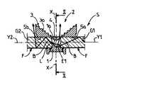
この装置は、発光ダイオード1から成る光源Lを有し、この発光ダイオードは、主要方向X−Xに(図1を基準に)、上向き方向、かつ主要方向X−Xに対して斜めの方向Bに、発光するようになっている。 This device has a light source L consisting of a light-emitting
少なくともダイオード1の近くには、長手方向軸線Y1が横に向くよう、細長い形状の光ガイドG1が配置されている。軸線Y1は、主要発光方向X−Xに対して直角であることが好ましい。光ガイドG1は、光ファイバーから構成でき、このガイドG1は、例えば図3に示すように、円形の直角断面を有する円筒形とすることができる。この直角断面は、円とは異なっていてもよい。光源Lに近いガイドG1の端面E1は、軸線Y1に対して直角となっている。 An elongated light guide G1 is disposed at least near the
方向Bは、面E1を通してガイドG1に入射するのに十分大きい角度だけ、方向X−Xに対して傾斜しているとき、斜めになっていると見なす。この角度は、約30度でよい。 The direction B is considered to be inclined when it is inclined with respect to the direction XX by an angle large enough to enter the guide G1 through the surface E1. This angle may be about 30 degrees.
ダイオード1の発光ゾーンの外側表面は、実質的に半球面である。面E1は、方向X−Xに平行な表面1aに対して接線方向にある。ダイオード1の反対側において、ガイドG1は、比較的長い長さだけ延びている。この長さは、500mmより長く、ガイドG1の直径は、約8mmとなっている。 The outer surface of the light emitting zone of the
光ガイドG1に整合し、軸線X−Xに対して対称的に、第2光ガイドG2が設けられていることが好ましい。このガイドG2の長手方向軸線Y2は、軸線Y1と整合している。 It is preferable that the second light guide G2 is provided in alignment with the light guide G1 and symmetrically with respect to the axis XX. The longitudinal axis Y2 of the guide G2 is aligned with the axis Y1.
方向X−Xに集光するための光学系2が、光源Lと関連している。この光学系2は、透明材料、例えばプラスチック材料の補助レンズ3を有する。この補助レンズ3は、ボウル状をしており、このボウルの凹部は、ダイオード1と反対を向いている。補助レンズの凹表面の横方向断面は、直角のステップ3aによって構成されており、これらステップは、図2に示されるように、光線が軸線X−Xに沿って集光されるのを保証するようになっている。 An
補助レンズの背面3bは、実質的に切頭円錐形であり、内部反射に好ましい角度に傾斜している。方向X−Xに対して直角な平面に位置するステップ3aの環状ゾーンには、レンズ状をした(図4参照)タイル要素3cを設けることができる。このタイル要素3cは、前方に凸状の表面を有し、光線の集光を強化するようになっている。補助レンズの凹状ゾーンの中心部分は、半凸レンズ要素4を構成し、その凸面は、発光ダイオード1に向いている。 The
補助レンズ3は、直径方向に対向する2つの円筒形ハウジング5aおよび5bを有し、これらハウジングは、方向X−Xに直角な軸線を有し、正確に内部に位置する光ガイドGB1およびG2の端部を収容するようになっている。 The
主要発光方向X−Xと同じ側で、光ガイドの軸線Y1およびY2に対して横方向に光を送るように、方向X−Xの光のための出口と反対に位置する光ガイドG1およびG2の表面Fは、変形されている。 Light guides G1 and G2 located on the same side as the main emission direction XX, opposite to the exit for the light in direction XX, so as to send light transverse to the axis Y1 and Y2 of the light guide The surface F is deformed.
変形された表面Fには、リブまたはノコギリ歯要素6を設けることがあり、これらの要素は、軸線Y1およびY2、および方向X−Xに直角なエッジを有する三角形の横断面を有するフレンネルプリズムを構成している。このように形成されたプリズムは、製造中に管状光ガイドG1およびG2内に組み込まれるストリップ7(図3)の背面を構成できる。このプリズムの製造は、モールド内に透明プラスチック材料を射出成形することによって行うことができる。 The deformed surface F may be provided with ribs or sawtooth elements 6, which are Frennel prisms having a triangular cross section with edges Y1 and Y2 and an angle perpendicular to the direction XX. Is configured. The prisms thus formed can constitute the back side of the strip 7 (FIG. 3) that is incorporated into the tubular light guides G1 and G2 during manufacture. The prism can be manufactured by injection molding a transparent plastic material in a mold.
方向X−Xに対して直角な状態で、軸線Y1、Y2と平行な方向に、平らな面8が延びる。 A flat surface 8 extends in a direction parallel to the axes Y1 and Y2 in a state perpendicular to the direction XX.
ノコギリ歯要素6の表面F、特に斜め表面は、金属被覆することができる。 The surface F, in particular the oblique surface, of the sawtooth element 6 can be metallized.
ノコギリ歯要素6は、光ガイドの一様な外観を改善するように、(材料内に形成された適当なプロフィルの孔の形態をした)光学的マイクロモチーフと置換できる。この光学的マイクロモチーフは、光ガイドG1、G2の後部基準表面8をレーザー加工することによって直接得るか、または射出成形中にモールド内に形成されるモチーフによって得られる。この場合には、ノコギリ歯要素6および/またはストリップ7は使用しない。 The sawtooth element 6 can be replaced with an optical micromotif (in the form of a suitable profile hole formed in the material) to improve the uniform appearance of the light guide. This optical micromotif is obtained directly by laser machining the rear reference surface 8 of the light guides G1, G2, or by a motif formed in the mold during injection molding. In this case, the sawtooth element 6 and / or the strip 7 are not used.
拡散ストリップの幅h(図3)、すなわち光ガイドの軸線を通過する平面、および方向X−Xに直角な方向の表面Fの大きさは、観察者が見る輝度の見かけの視野を広げるように計算される。水平な光ガイドG1、G2に対し、輝度視野角は、水平平面に対して±10度となっていることが好ましい。 The width h of the diffusing strip (FIG. 3), ie the plane passing through the axis of the light guide, and the size of the surface F in the direction perpendicular to the direction XX, widen the apparent field of brightness seen by the viewer. Calculated. For the horizontal light guides G1 and G2, the luminance viewing angle is preferably ± 10 degrees with respect to the horizontal plane.
光学系をほぼ垂直な方向で使用するケースでは、水平平面における視覚性のゾーンを広げるように、この輝度視野角は、より大きく選択される。 In the case of using the optical system in a substantially vertical direction, this luminance viewing angle is selected to be larger so as to widen the visibility zone in the horizontal plane.
図7に示すように、横方向の円形断面を有する光ガイドG1の円筒形状によって、従来の拡大効果以外に、拡散ゾーンを大きくすることが可能となっている。 As shown in FIG. 7, the cylindrical shape of the light guide G1 having a circular cross section in the lateral direction makes it possible to enlarge the diffusion zone in addition to the conventional enlargement effect.
この信号装置は、次のように作動する。
発光ダイオード1を点灯すると、方向X−Xに主な発光が生じる。輝度強度は、レンズ4および補助レンズ34を構成する光学的装置により集中させられる。This signaling device operates as follows.
When the
この信号機能は、比較的強い輝度強度によって集中させられる。 This signal function is concentrated by a relatively strong luminance intensity.
光線Bのような斜め光線から、光ガイドG1およびG1の長手方向に従い、補助レンズ3の両側で、極めて長く、一様な第2信号機能が得られる。光線Bは、光ガイドの内部で反射され、表面Fを通って前方に、すなわち、主な発光と同じ側で放出される。 A very long and uniform second signal function can be obtained on both sides of the
従って、本発明の信号装置は、次のように2つの相補的サブアセンブリに分解できる。 Thus, the signaling device of the present invention can be broken down into two complementary subassemblies as follows.
すなわち、ダイオード1および相補的レンズ3に対応する中心部分:この部分の目的は、本例では例えば「高所ストップライト」機能と見なされる主要機能を実行することにあり、この機能は、補助レンズ3の材料の内部反射特性を活用する一方、中心部分の形状は、スタイルおよび相対的性能の条件に従い、上記機能を満足するようにできる。 That is, the central part corresponding to the
光ガイドG1およびG2から成る2つの付属品:これら2つの付属品により、極めて長い長さにわたって、一様な照明機能を奏し、車両のラインを強調するような流線形スタイルを生じさせることができる。 Two accessories consisting of light guides G1 and G2: These two accessories can produce a streamlined style that provides a uniform lighting function over a very long length and emphasizes the lines of the vehicle .
当然ながら、補助レンズ3に対する対称的直線状機能を達成することができる。この直線状機能によって、補助レンズ3は極めて長い長さにわたって、従来の信号機能に適合し、特に「ブレーク」タイプの自動車の輪郭を強調することができる。これに関連し、従来の光学手段を用いた場合、多少アクセスしにくいゾーンに、輝度信号かシステムを設置することは困難である。 Of course, a symmetrical linear function for the
図6は、補助レンズ3の両側に延びる極めて長い2つの光ガイドG1およびG2を備える光学系を示す。 FIG. 6 shows an optical system comprising two very long light guides
例えば光ガイドは、後部ウィンドーの曲線に従うか、または自動車の車体、またはアウトラインの一部に従うことができるようになっている。 For example, the light guide can follow the curve of the rear window or follow the car body or part of the outline.
本例では、発光ダイオード1の両側に、直径方向に対向する2つの光ガイドが配置されており、共通平面に、3つ以上のガイド、例えば4つのガイドを設けることができる。この場合、ガイドの光出力を、90度の回転角だけオフセットする。 In this example, two light guides facing each other in the diametrical direction are arranged on both sides of the
光ガイドの総長は、1300mmを超えることができる。光ガイドの形状は、このガイドを支持している車両のスタイルに従うように適合できる。補助レンズ3から成る中心部品を丸するか、または長方形とし、その寸法を、条件に従って20〜30mmとすることができる。 The total length of the light guide can exceed 1300 mm. The shape of the light guide can be adapted to follow the style of the vehicle supporting this guide. The central part consisting of the
図14に示すように、光ガイド内で光ビームをコリメート化し、すなわち実質的に平行とし、発光ダイオード1から離間した光ガイドの端部N1(図3および6)に向かう光量を増すように、光ガイドの入力面に収束レンズMを設けると有利である。 As shown in FIG. 14, the light beam is collimated within the light guide, i.e. substantially parallel, so as to increase the amount of light toward the light guide end N1 (FIGS. 3 and 6) spaced from the
この端部N1(図3)は、光ガイドの長手方向軸線に対して直角な平らな面から成っていることが好ましく、この面は、光ガイドG1またはG2の内部に光を伝えるように金属被覆されている。このようにして、この光学系の光出力は改善される。 This end N1 (FIG. 3) preferably consists of a flat surface perpendicular to the longitudinal axis of the light guide, this surface being metal to carry light into the light guide G1 or G2. It is covered. In this way, the light output of this optical system is improved.
信号機能を達成するように、多数の構造を採用できる。 A number of structures can be employed to achieve the signaling function.
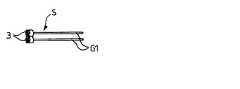
図8は、2つの補助レンズ3と、並置された2つの対応する光源を備える非対称的な構造を示し、各補助レンズと1つの光源G1とは関連している。2つの光源G1は、平行で、実質的に垂直で、かつ直線状であり、補助レンズ3の同じ側に配置されている。 FIG. 8 shows an asymmetric structure with two
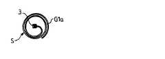
図9は、補助レンズ3と、光ガイドG1aの中心に設けられた光源とを備える構造を示し、光ガイドは、前記補助レンズから延び、共通平面に2つの回転部を有する実質的に円形の螺旋体として形成されている。 FIG. 9 shows a structure comprising an
図10は、光源と共に中心に補助レンズ3を含む信号装置を示す。前記補助レンズから、径方向に対向する2つの光ガイドG1bおよびG2bが延びており、共通平面において、反対方向に半分の巻線として実質的に湾曲しているので、全体のモチーフはS字状となっている。 FIG. 10 shows a signal device including an
変形例では、光ガイドが形成する曲線は、1つの平面に位置しない曲がった曲線とすることができる。 In a variation, the curve formed by the light guide can be a curved curve that is not located on one plane.
図11は、2つの平行な光ガイドG1が、補助レンズの同じ側に位置し、水平となっている、図8の変形例を示す。 FIG. 11 shows a modification of FIG. 8 in which two parallel light guides G1 are located on the same side of the auxiliary lens and are horizontal.
ストップライト、パーキングライト、方向指示器、バックライトおよびその他の機能を含む多数の機能を得ることができる。 Numerous functions can be obtained including stop lights, parking lights, turn signals, backlights and other functions.
スタイリングの可能性を多くすることができるように、少なくとも1つの相補的光ガイドと組み合わされた光源、特に発光ダイオード1を備えた中心光学系から成る種々の設計をすることもできる。 In order to increase the possibility of styling, various designs can also be made of a central optical system with a light source, in particular a light-emitting
所望のスタイルを得るように、これらの部品を組み合わせることができる。光学系の中心または光学系の端部の各々に、主要光源を配置することによって、対称的なバージョンが得られる。光束を最良に活用する機能が得られるようにするために、光学的性能を高めるよう、対称的なバージョンを別個にしてもよいし、数個のユニットのグループとして、(図8および11に示されるように)2つ以上のアセンブリにまとめてもよい。 These parts can be combined to obtain the desired style. By placing a main light source at each of the center of the optical system or at the end of the optical system, a symmetric version is obtained. In order to obtain the best use of the luminous flux, the symmetric version may be separated to enhance the optical performance, or as a group of several units (shown in FIGS. 8 and 11). As may be combined into two or more assemblies.
これらのバージョンは(図8および図11に示すように)直線状でもよいし、または(図9に示すように)円形でもよいし、または(図10に示すように)多少とも曲線状としてもよい。このようにすることによって、装置をスタイルまたは形状の要求に合わせることができる。 These versions may be linear (as shown in FIGS. 8 and 11), circular (as shown in FIG. 9), or somewhat curvilinear (as shown in FIG. 10). Good. In this way, the device can be tailored to style or shape requirements.
図12は、拡散光ガイドGaによって接続された、中間パワーの4つの離間した主要光源Laを活用する直線状信号装置Saを示す。これら光源Laの距離は、異なっていてもよい。 FIG. 12 shows a linear signal device Sa that utilizes four spaced apart main light sources La of intermediate power connected by a diffused light guide Ga. The distances of these light sources La may be different.
当然ながら、光源Laの数が異なる別の構造、特に光ガイドの各端部に1つの光源が設けられた2つの光源しか設けない別の構造も可能である。 Of course, other structures with different numbers of light sources La, in particular other structures with only two light sources with one light source at each end of the light guide, are possible.
図13では、信号装置は2つの光源Laしか有しておらず、光ガイドGbの各端部に、1つの光源が設けられている。光ガイド10bは、離間した中立ゾーン9を有し、この中立ゾーンにおいて、外側に向かう光の拡散が抑制されているので、このゾーン9は、点灯されていないように見える。従って、連続した光のラインと対照的に、「点描」タイプの信号装置を得ることができる。 In FIG. 13, the signal device has only two light sources La, and one light source is provided at each end of the light guide Gb. The light guide 10b has a neutral zone 9 that is spaced apart, and in this neutral zone, the diffusion of light toward the outside is suppressed, so this zone 9 appears to be unlit. Thus, a “stipple” type signal device can be obtained as opposed to a continuous line of light.
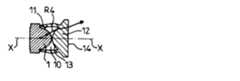
図14は、信号装置Fbのモノブロック構造を示す。この構造では、対向する2つの光ガイドG1とG2とは単一部品を構成し、その部品の接合ゾーンは、光ガイドの長手方向軸線に直角に対称平面Pを構成する。図14の平面を通過する接合ゾーンの輪郭の断面は、広い開口部を有するV字形となっており、このV字形の分岐は、外側に凸状となっている。この分岐は、内側に向かってカーブし、接合ゾーンよりも直径の小さい光ガイドの円筒形部分に接合している。 FIG. 14 shows a monoblock structure of the signal device Fb. In this structure, the two opposing light guides G1 and G2 constitute a single part, and the joining zone of the parts constitutes a symmetrical plane P perpendicular to the longitudinal axis of the light guide. The cross section of the outline of the joining zone passing through the plane of FIG. 14 has a V shape having a wide opening, and the V-shaped branch is convex outward. This branch is curved inward and joined to the cylindrical portion of the light guide that is smaller in diameter than the joining zone.
接合ゾーンには、発光ダイオード1のためのハウジング10が設けられている。このハウジング10は、アパーチャー10a(図15)において、後方を向くよう開口しており、このアパーチャーを通るように発光ダイオード1を挿入できる。このハウジングの内側表面は、ゾーン11のようなゾーン(図16参照)を有し、このゾーンによって、ダイオードの輪郭を囲み、ダイオード1をハウジング内に保持し、センタリングすることができる。 A
光ガイドG1およびG2内の光に対する入力面は、2つの光線R1およびR2と共に略示されているように、各光ガイド内で、光ビームをコリメート化するための凸レンズMから成り、2つの光線R1およびR2は、レンズMの凸面に入射する前にハウジング10内で発散し、光ガイド内で実質的に平行となる。 The input surface for the light in the light guides G1 and G2 consists of a convex lens M for collimating the light beam in each light guide, as schematically shown with the two light rays R1 and R2. R1 and R2 diverge in the
光線R3のような光線は、レンズMの輪郭を超えて、光ガイドに入射し、この光ガイド内で内部反射をし、次に前方に透過される。 A light ray, such as light ray R3, enters the light guide beyond the contour of the lens M, undergoes internal reflection within the light guide, and is then transmitted forward.
ハウジング10の前方は、半凸レンズ12によって閉じられている。このレンズの凸面13は、ハウジング9の内側を向いており、平らな面14は、外側を向いている。発光ダイオード1の半球形部分の極は、面13の極に接近している。光ガイドG1およびG2には、レンズの平らな面14の両側に位置する斜めのファセット15(図18参照)が形成されており、この光ガイドは、方向X−Xに対して傾斜し、図15の平面に対して直角な平面に形成されている。 The front of the
図16は、発光ダイオード1によって発生された光線R4の光路を示す。この光路は、レンズ14を通過した後に、方向X−Xに対して多少傾斜している。 FIG. 16 shows the optical path of the light ray R4 generated by the
図15および図16の構造では、レンズ12は一体化されている。すなわち、光ガイドG1およびG2と共に一体部品として形成されている。 In the structure of FIGS. 15 and 16, the
図17および図18の変形例では、ハウジング10は、前方に向かって開口しており、ハウジング10の前方アパーチャーには、独立したレンズ12が固定されている。 17 and 18, the
光線、例えば光線R1およびR2によって形成されたビームのコリメート化された部分によって、発光ダイオード1からの光ガイドの端部で、ビームの輝度を高めることが可能となっている。 The collimated part of the beam formed by the light rays, for example light rays R1 and R2, makes it possible to increase the brightness of the beam at the end of the light guide from the
図14〜図18の変形例では、信号システムは、特にその中心ゾーンで、よりコンパクトとなっている。接合ゾーンにおける光ガイドの内側および外側形状は、中心レンズの可視面14と側方光ガイドG1およびG2との間の光束の分布を最適にするようになっている。このように、この信号機能において、種々のゾーンの相対的輝度を調節することが可能となっている。 In the variant of FIGS. 14-18, the signaling system is more compact, especially in its central zone. The inner and outer shapes of the light guides in the joining zone are designed to optimize the distribution of the light flux between the central lens
光ガイドの一様な外観は、レンズMによって、コリメート化された光により、改善されている。 The uniform appearance of the light guide is improved by the lens M due to the collimated light.
このような設計は、図14〜図18に示されるようなモノブロック形状として行うこともできるし、または射出成形に使用されるモールドを簡略化できるようにするサブアセンブリにまとめることによって行うこともできる。 Such a design can be done as a monoblock shape as shown in FIGS. 14-18, or it can be done by grouping it into a subassembly that allows the mold used for injection molding to be simplified. it can.
この光ガイドは、例えば内側キャビンの特徴である曲がった表面に従うように、三次元形状とすることができる。 This light guide can be in a three-dimensional shape, for example to follow the curved surface that is characteristic of the inner cabin.
フリー形状を有する自動車のヘッドライトにおいて、パーキングライト機能を得ることができる。 A parking light function can be obtained in a headlight of an automobile having a free shape.
マイクロリブまたはマイクロオプティクスを使用することにより、連続的に一様な照明された外観を保証するように、後方部分を適合することにより、長方形、すなわち円形から長方形に変形されたプロフィルを想到することもできる。 By using microribs or microoptics, conceiving a profile that is deformed from a rectangle, ie from a circle to a rectangle, by adapting the rear part to ensure a continuously uniform illuminated appearance. You can also.
本発明によれば、少ない数の発光ダイオードで、良好な信号機能を得ることができる。または本装置は、適用能力において極めてフレキシブルであるので、種々の機能、例えば白色発光ダイオードを使った信号または内部照明機能を発揮することができる。 According to the present invention, a good signal function can be obtained with a small number of light emitting diodes. Alternatively, the device is very flexible in application capability and can therefore perform various functions, such as signals using white light emitting diodes or internal lighting functions.
また本発明の装置は、長距離にわたって光を透過できるよう、透明プラスチック材料の性質と共に、発光ダイオードが放出する低温光によって得られる可能性を活用することにより、車両のためのシグネーチャを提供するよう、スタイリング効果を与えることができる。 The device of the present invention also provides a signature for a vehicle by taking advantage of the low-temperature light emitted by the light emitting diodes along with the properties of the transparent plastic material so that light can be transmitted over long distances. Can give a styling effect.
本装置を製造するのに、公知の製造方法、例えば高温デポジションによる金属被覆されたフィルムのデポジション、または表面機械加工、またはレーザー処理による表面処理、および部品の射出成形を使用できる。 Known manufacturing methods can be used to manufacture the device, such as deposition of a metallized film by high temperature deposition, or surface machining by laser processing, or injection molding of parts.
発光ダイオードは、光ガイドによって変更されない単色の光を放出するので、放出される光は、ネオンチューブで得られる光よりも輝度が高い。 Since the light emitting diode emits monochromatic light that is not changed by the light guide, the emitted light has a higher brightness than the light obtained in the neon tube.
上記装置の変形バージョンは、図19に示されるように、発光ダイオード1b、1c状をした、または特殊な種類のいくつかの基本的光源から成る光源Lcを活用することを含む。このダイオードは、主要発光方向X−Xが互いに平行となるように、支持体16に固定されている。 A modified version of the device includes utilizing a light source Lc in the form of a
二次側方光源を構成する1つ以上の発光ダイオード1cは、関連する特定機能の照明表面積を広くするように、複数の管状光ガイドG1c、G2cのうちの関連する1つに光を送る。光ガイドの端面17bまたは17cは、光ガイドの軸線に対して、例えば45度だけ傾斜している。発光ダイオード1cによって主要方向に放出される光は、対応する光ガイド内の面17bまたは17cを透過する。各管状光ガイドに対して、1つの発光ダイオードを設けることが好ましい。 One or more light emitting diodes 1c constituting the secondary side light source send light to an associated one of the plurality of tubular light guides G1c, G2c so as to increase the illumination surface area of the associated specific function. The
主要機能を得るのに、1つ以上の発光ダイオード1bが使用されている。これらのダイオードは、得るべき信号機能(すなわちCHMLS、ストップライト、またはパーキングライトもしくは方向指示ライト)に固有の1つ以上の光学系18と関連している。上記補助レンズ3と多少同一の態様で、または必要とされる最終スタイルに従う特定のリフレクタを有するシステムを通過するように光を分散させるレンズの形態に、主要機能の光学系18を製造できる。光学系18は、中心位置を占め、光ガイドG1、G2は、横方向に位置することが好ましい。 One or more
B 光線
E1 端面
G1 光ガイド
G2 第2光ガイド
L 光源
S 信号装置
1 発光ダイオード
2 光学系
3 補助レンズ
3a ステップ
3c タイル要素
4 半凸レンズ要素
5a ハウジング
5b ハウジング
6 ノコギリ歯要素
7 ストリップ
8 平らな面
9 中立ゾーン
10 ハウジング
10a アパーチャー
11 ゾーン
14 可視面
18 光学系B light beam E1 end face G1 light guide G2 second light guide L light source S
Claims (14)
Translated fromJapanese(a)主発光方向を有する光束を発する少なくとも1つの光源と、
(b)前記主発光方向への発光を集光するため、光を放つ前に光を内部反射させるよう適度な角度に配向された、ファセットを有する、透明材料製の補助レンズを備える、光学系と、
(c)第1の端面と、第2の端面と、第1及び第2の両端面の間に延びる周側面とを有する細長の本体を有する少なくとも1つの光ガイドと
を備え、前記第1の端面は、前記光源に近接し該主発光方向に対して垂直であり、
前記光源からの光束の一部が、前記光ガイドとは独立して、第1の光強度を有する第1信号機能・照明機能を発揮し、前記光源からの光束の別の一部が、前記光ガイドに前記第1の端面から入射して前記周側面から発せられることで、第1の光強度よりも弱い第2の光強度を有する第2信号機能・照明機能が提供されるようになっていることを特徴とする、信号・照明装置。A signal / lighting device for automobiles,
(A) at least one light sourcethat emits a light beam having a main emission direction ;
(B) an optical system comprising an auxiliary lens made of a transparent material having a facet, which is oriented at an appropriate angle so as to internally reflect the light before emitting the light in order to collect the light emitted in the main light emitting direction. When,
(C) at least one light guide having an elongated body having a first end face, a second end face, and a peripheral side surface extending between the first and second end faces;
The first end face is close to the light source and perpendicular to the main light emission direction;
A part of the light flux from the light source exhibits a first signal function / illumination function having a first light intensity independently of the light guide, and another part of the light flux from the light source A second signal function / illumination function having a second light intensity that is weaker than the first light intensity is provided by being incident on the light guide from the first end surface and emitted from the peripheral side surface. A signal / lighting device.
Applications Claiming Priority (1)
| Application Number | Priority Date | Filing Date | Title |
|---|---|---|---|
| FR0315115AFR2864204B1 (en) | 2003-12-19 | 2003-12-19 | SIGNALING OR LIGHTING DEVICE, IN PARTICULAR FOR MOTOR VEHICLE |
Publications (2)
| Publication Number | Publication Date |
|---|---|
| JP2005193892A JP2005193892A (en) | 2005-07-21 |
| JP4664662B2true JP4664662B2 (en) | 2011-04-06 |
Family
ID=34531314
Family Applications (1)
| Application Number | Title | Priority Date | Filing Date |
|---|---|---|---|
| JP2004364197AExpired - Fee RelatedJP4664662B2 (en) | 2003-12-19 | 2004-12-16 | Signal or lighting equipment for automobiles |
Country Status (8)
| Country | Link |
|---|---|
| US (1) | US7452114B2 (en) |
| EP (1) | EP1547865B1 (en) |
| JP (1) | JP4664662B2 (en) |
| AT (1) | ATE352454T1 (en) |
| DE (1) | DE602004004490T2 (en) |
| ES (1) | ES2280919T3 (en) |
| FR (1) | FR2864204B1 (en) |
| PL (1) | PL1547865T3 (en) |
Families Citing this family (31)
| Publication number | Priority date | Publication date | Assignee | Title |
|---|---|---|---|---|
| DE102005043992B4 (en)* | 2005-09-14 | 2010-04-08 | Automotive Lighting Reutlingen Gmbh | Signal light of a vehicle |
| US7489453B2 (en)* | 2005-11-15 | 2009-02-10 | Visteon Global Technologies, Inc. | Side emitting near field lens |
| FR2894904B1 (en)* | 2005-12-20 | 2009-07-10 | Valeo Vision Sa | OPTICALLY GUIDED LIGHTING OR SIGNALING DEVICE FOR MOTOR VEHICLE |
| JP4770731B2 (en)* | 2006-12-27 | 2011-09-14 | 三菱自動車工業株式会社 | Indirect lighting system for passenger compartment |
| FR2927404B1 (en)* | 2008-02-12 | 2015-01-23 | Valeo Vision | OPTICAL SYSTEM WITH MAIN FUNCTION AND DECORATIVE FUNCTION FOR MOTOR VEHICLE |
| JP4479805B2 (en)* | 2008-02-15 | 2010-06-09 | ソニー株式会社 | Lens, light source unit, backlight device, and display device |
| DE102008035765A1 (en)* | 2008-07-31 | 2010-02-04 | Automotive Lighting Reutlingen Gmbh | lighting device |
| DE102008060353B4 (en) | 2008-12-03 | 2021-08-19 | Audi Ag | Illuminated panel |
| US8398283B2 (en)* | 2009-01-21 | 2013-03-19 | Magna International, Inc. | Automotive signal light employing multi-focal length light pipes |
| WO2010124158A1 (en) | 2009-04-24 | 2010-10-28 | 3M Innovative Properties Company | Light assembly |
| TW201213727A (en)* | 2010-09-23 | 2012-04-01 | Enti Company Ltd | Light emitting diode illumination light source module installed in medical illumination lamp |
| EP2748658B1 (en) | 2011-11-03 | 2015-10-21 | Koninklijke Philips N.V. | Led rear lamp, in particular for a bicycle |
| CN202955594U (en)* | 2012-10-30 | 2013-05-29 | 广东骑光车灯工业有限公司 | Novel turn signal lamp of motorcycle |
| JP6082264B2 (en)* | 2013-02-14 | 2017-02-15 | スタンレー電気株式会社 | Light guide lens and lamp |
| JP5955303B2 (en)* | 2013-11-19 | 2016-07-20 | 株式会社小糸製作所 | Door handle |
| JP6478204B2 (en) | 2014-02-03 | 2019-03-06 | パナソニックIpマネジメント株式会社 | LIGHTING DEVICE AND AUTOMOBILE HAVING LIGHTING DEVICE |
| CN105318207B (en)* | 2014-06-30 | 2019-01-15 | 欧普照明股份有限公司 | A kind of lamps and lanterns |
| US9815501B2 (en) | 2014-10-21 | 2017-11-14 | Great Dane Llc | Cargo vehicle and molding assembly for a cargo vehicle |
| US10066804B2 (en)* | 2016-05-31 | 2018-09-04 | GM Global Technology Operations LLC | Lighting assembly with integrated optical diffuser |
| JP6744196B2 (en)* | 2016-10-31 | 2020-08-19 | スタンレー電気株式会社 | Vehicle lighting |
| JP6540655B2 (en) | 2016-11-02 | 2019-07-10 | トヨタ自動車株式会社 | Overhead console and body superstructure |
| JP7020259B2 (en) | 2018-04-09 | 2022-02-16 | トヨタ自動車株式会社 | Vehicle lighting |
| CN108626679B (en)* | 2018-05-22 | 2024-05-17 | 常州星宇车灯股份有限公司 | Light guide-based light source assembly for motor vehicle |
| FR3092900B1 (en)* | 2019-02-14 | 2022-07-15 | Psa Automobiles Sa | Lighting and/or light-signalling device for a motor vehicle. |
| CN111665589B (en)* | 2019-03-08 | 2024-10-15 | 三美电机株式会社 | Light guide and light emitting device |
| JP7343783B2 (en)* | 2019-03-08 | 2023-09-13 | ミツミ電機株式会社 | Light guide and light emitting device |
| US10950743B2 (en)* | 2019-05-02 | 2021-03-16 | Stmicroelectronics (Research & Development) Limited | Time of flight (TOF) sensor with transmit optic providing for reduced parallax effect |
| DE102020101875A1 (en) | 2020-01-27 | 2021-07-29 | Webasto SE | Lighting arrangement for a vehicle roof and vehicle roof for a motor vehicle |
| DE102020113177A1 (en) | 2020-05-15 | 2021-11-18 | Bayerische Motoren Werke Aktiengesellschaft | Lighting device for the interior of a motor vehicle |
| US11703202B2 (en)* | 2021-08-10 | 2023-07-18 | ams OSRAM Automotive Lighting Systems USA Inc. | Image projection lighting assembly |
| DE102024105156A1 (en)* | 2024-02-23 | 2025-08-28 | Marelli Automotive Lighting Reutlingen (Germany) GmbH | Lighting device for a vehicle and vehicle with at least one such lighting device |
Family Cites Families (15)
| Publication number | Priority date | Publication date | Assignee | Title |
|---|---|---|---|---|
| US3532871A (en)* | 1968-05-20 | 1970-10-06 | Ford Motor Co | Combination running light-reflector |
| EP0055732A4 (en)* | 1980-07-14 | 1982-11-16 | Frank Oliver Eyres Young | Vehicle illumination device. |
| JP2823156B2 (en)* | 1985-07-23 | 1998-11-11 | キヤノン株式会社 | Display device |
| US4862330A (en)* | 1987-09-21 | 1989-08-29 | Koito Manufacturing Co., Ltd. | Vehicle lamp |
| US4947293A (en)* | 1989-03-03 | 1990-08-07 | Johnson Glenn M | Cargo vehicle perimeter clearance lighting system |
| DE4117278A1 (en) | 1991-05-27 | 1992-12-03 | Hella Kg Hueck & Co | INTERIOR LIGHT FOR MOTOR VEHICLES |
| EP1005619B1 (en)* | 1997-08-12 | 2001-11-21 | Decoma International Inc. | Bireflective lens element |
| JPH11284803A (en)* | 1998-03-27 | 1999-10-15 | Citizen Electronics Co Ltd | Linear light source unit |
| DE19857561A1 (en)* | 1998-12-14 | 2000-06-21 | Valeo Beleuchtung Deutschland | Vehicle light includes light guide rod, luminous diodes, and light inlet surface and opposite end surface formed as light deflecting region |
| DE10137605A1 (en)* | 2001-08-01 | 2003-02-27 | Hella Kg Hueck & Co | Light for vehicles |
| FR2836208B1 (en)* | 2002-02-21 | 2004-09-03 | Valeo Vision | SIGNALING LIGHT COMPRISING AN OPTICAL PART PROVIDING AN AUTONOMOUS SIGNALING FUNCTION |
| US6565244B1 (en)* | 2002-04-02 | 2003-05-20 | Peterson Manufacturing Company | Single source identification light bar |
| US6724543B1 (en)* | 2002-10-23 | 2004-04-20 | Visteon Global Technologies, Inc. | Light collection assembly having mixed conic shapes for use with various light emitting sources |
| FR2846400B1 (en)* | 2002-10-28 | 2005-10-07 | Valeo Vision | SIGNALING LIGHT COMPRISING A DEVICE FOR RECOVERING AND DISTRIBUTING THE LUMINOUS FLOW TO AN ANNULAR REFLECTOR |
| US7293906B2 (en)* | 2005-05-23 | 2007-11-13 | Avago Technologies Ecbu Ip (Singapore) Pte Ltd | Light source adapted for LCD back-lit displays |
- 2003
- 2003-12-19FRFR0315115Apatent/FR2864204B1/ennot_activeExpired - Fee Related
- 2004
- 2004-12-06ESES04292894Tpatent/ES2280919T3/ennot_activeExpired - Lifetime
- 2004-12-06PLPL04292894Tpatent/PL1547865T3/enunknown
- 2004-12-06DEDE602004004490Tpatent/DE602004004490T2/ennot_activeExpired - Lifetime
- 2004-12-06EPEP04292894Apatent/EP1547865B1/ennot_activeRevoked
- 2004-12-06ATAT04292894Tpatent/ATE352454T1/ennot_activeIP Right Cessation
- 2004-12-15USUS11/013,272patent/US7452114B2/ennot_activeExpired - Fee Related
- 2004-12-16JPJP2004364197Apatent/JP4664662B2/ennot_activeExpired - Fee Related
Also Published As
| Publication number | Publication date |
|---|---|
| EP1547865A1 (en) | 2005-06-29 |
| EP1547865B1 (en) | 2007-01-24 |
| ES2280919T3 (en) | 2007-09-16 |
| JP2005193892A (en) | 2005-07-21 |
| FR2864204A1 (en) | 2005-06-24 |
| DE602004004490T2 (en) | 2008-01-03 |
| US20050141213A1 (en) | 2005-06-30 |
| DE602004004490D1 (en) | 2007-03-15 |
| US7452114B2 (en) | 2008-11-18 |
| ATE352454T1 (en) | 2007-02-15 |
| PL1547865T3 (en) | 2007-06-29 |
| FR2864204B1 (en) | 2006-10-27 |
Similar Documents
| Publication | Publication Date | Title |
|---|---|---|
| JP4664662B2 (en) | Signal or lighting equipment for automobiles | |
| US4371916A (en) | Motor-vehicle lamp with base area illumination | |
| EP1355108A2 (en) | Lighting device for motor vehicles | |
| JP2000215710A (en) | Multi-functional taillight device for vehicle | |
| JPH09167515A (en) | Peripheral optical elements that change the direction of light from the LED | |
| US5097395A (en) | Multiple cavity light fixture | |
| JP2007311352A (en) | Vehicle lighting and/or signaling device | |
| JP2004235153A (en) | Light guide with reflector | |
| JP2012169231A (en) | Vehicular lamp | |
| JP7081977B2 (en) | Vehicle lighting | |
| JP2007180027A (en) | Lighting or signalling device with optical guide for automobile | |
| US5692827A (en) | Tail lamp for an automotive vehicle using an elongated hyperbolic cylinder | |
| JP7418492B2 (en) | Vehicle lights | |
| JP2018041711A (en) | Lens including wraparound light guide part and vehicular lighting fixture | |
| CN110220162B (en) | Optical element, lighting module, signal lighting multiplexing module, car lamp and car | |
| CN1789790A (en) | Lighting system or signalling device with light guide | |
| US20050286262A1 (en) | Lighting and/or signalling device with optical guide | |
| WO2020244080A1 (en) | Vehicle light optical element, vehicle light module, vehicle headlight, and vehicle | |
| US11498480B2 (en) | Illuminating device for vehicle ceiling lamp | |
| JP2008293795A (en) | Vehicle lighting | |
| JP2018120658A (en) | Vehicular lighting fixture | |
| CN115127080A (en) | Multifunctional composite automotive signal light optical components | |
| EP1500872B1 (en) | Vehicle lighting device with an annular reflector, and relative improved reflector | |
| JP7023780B2 (en) | Vehicle lighting | |
| JP5363179B2 (en) | Vehicle lighting |
Legal Events
| Date | Code | Title | Description |
|---|---|---|---|
| A621 | Written request for application examination | Free format text:JAPANESE INTERMEDIATE CODE: A621 Effective date:20071217 | |
| A131 | Notification of reasons for refusal | Free format text:JAPANESE INTERMEDIATE CODE: A131 Effective date:20100727 | |
| A601 | Written request for extension of time | Free format text:JAPANESE INTERMEDIATE CODE: A601 Effective date:20101027 | |
| A602 | Written permission of extension of time | Free format text:JAPANESE INTERMEDIATE CODE: A602 Effective date:20101101 | |
| A521 | Request for written amendment filed | Free format text:JAPANESE INTERMEDIATE CODE: A523 Effective date:20101129 | |
| TRDD | Decision of grant or rejection written | ||
| A01 | Written decision to grant a patent or to grant a registration (utility model) | Free format text:JAPANESE INTERMEDIATE CODE: A01 Effective date:20101221 | |
| A01 | Written decision to grant a patent or to grant a registration (utility model) | Free format text:JAPANESE INTERMEDIATE CODE: A01 | |
| A61 | First payment of annual fees (during grant procedure) | Free format text:JAPANESE INTERMEDIATE CODE: A61 Effective date:20110107 | |
| R150 | Certificate of patent or registration of utility model | Free format text:JAPANESE INTERMEDIATE CODE: R150 Ref document number:4664662 Country of ref document:JP Free format text:JAPANESE INTERMEDIATE CODE: R150 | |
| FPAY | Renewal fee payment (event date is renewal date of database) | Free format text:PAYMENT UNTIL: 20140114 Year of fee payment:3 | |
| R250 | Receipt of annual fees | Free format text:JAPANESE INTERMEDIATE CODE: R250 | |
| R250 | Receipt of annual fees | Free format text:JAPANESE INTERMEDIATE CODE: R250 | |
| R250 | Receipt of annual fees | Free format text:JAPANESE INTERMEDIATE CODE: R250 | |
| R250 | Receipt of annual fees | Free format text:JAPANESE INTERMEDIATE CODE: R250 | |
| R250 | Receipt of annual fees | Free format text:JAPANESE INTERMEDIATE CODE: R250 | |
| R250 | Receipt of annual fees | Free format text:JAPANESE INTERMEDIATE CODE: R250 | |
| R250 | Receipt of annual fees | Free format text:JAPANESE INTERMEDIATE CODE: R250 | |
| LAPS | Cancellation because of no payment of annual fees |