JP4664362B2 - Electrical device, method for identifying host device, method for determining power availability of power supply, and method for managing power usage of electrical device - Google Patents
Electrical device, method for identifying host device, method for determining power availability of power supply, and method for managing power usage of electrical deviceDownload PDFInfo
- Publication number
- JP4664362B2 JP4664362B2JP2007522569AJP2007522569AJP4664362B2JP 4664362 B2JP4664362 B2JP 4664362B2JP 2007522569 AJP2007522569 AJP 2007522569AJP 2007522569 AJP2007522569 AJP 2007522569AJP 4664362 B2JP4664362 B2JP 4664362B2
- Authority
- JP
- Japan
- Prior art keywords
- power
- digital data
- level
- peripheral
- available
- Prior art date
- Legal status (The legal status is an assumption and is not a legal conclusion. Google has not performed a legal analysis and makes no representation as to the accuracy of the status listed.)
- Expired - Lifetime
Links
Images


Classifications
- G—PHYSICS
- G06—COMPUTING OR CALCULATING; COUNTING
- G06F—ELECTRIC DIGITAL DATA PROCESSING
- G06F1/00—Details not covered by groups G06F3/00 - G06F13/00 and G06F21/00
- G06F1/26—Power supply means, e.g. regulation thereof
- G06F1/266—Arrangements to supply power to external peripherals either directly from the computer or under computer control, e.g. supply of power through the communication port, computer controlled power-strips
- G—PHYSICS
- G06—COMPUTING OR CALCULATING; COUNTING
- G06F—ELECTRIC DIGITAL DATA PROCESSING
- G06F1/00—Details not covered by groups G06F3/00 - G06F13/00 and G06F21/00
- G06F1/26—Power supply means, e.g. regulation thereof
- G—PHYSICS
- G06—COMPUTING OR CALCULATING; COUNTING
- G06F—ELECTRIC DIGITAL DATA PROCESSING
- G06F1/00—Details not covered by groups G06F3/00 - G06F13/00 and G06F21/00
- G06F1/26—Power supply means, e.g. regulation thereof
- G06F1/30—Means for acting in the event of power-supply failure or interruption, e.g. power-supply fluctuations
Landscapes
- Engineering & Computer Science (AREA)
- Theoretical Computer Science (AREA)
- General Engineering & Computer Science (AREA)
- Physics & Mathematics (AREA)
- General Physics & Mathematics (AREA)
- Computer Hardware Design (AREA)
- Power Sources (AREA)
- Charge And Discharge Circuits For Batteries Or The Like (AREA)
Description
Translated fromJapanese本発明は、電子装置に関し、特に、周辺バス(peripheral bus)に連結(couple)可能なポータブル電子装置に関する。 The present invention relates to an electronic device, and more particularly, to a portable electronic device that can be coupled to a peripheral bus.
ポータブルディジタルアシスタントやメディアプレーヤなどのポータブル電子装置は、多くの場合、バッテリから電力の供給を受ける。これらの電子装置は、時には、Universal SerialBus (USB)またはFireWire(登録商標)(IEEE1394)バスポートのような、周辺バスをサポート可能な周辺バスポートを有する。周辺バスは、電子装置間のデータ通信の提供は勿論のこと、電子装置への制限された電力の供給にも使用される。 Portable electronic devices such as portable digital assistants and media players are often powered from a battery. These electronic devices sometimes have a peripheral bus port capable of supporting a peripheral bus, such as a Universal Serial Bus (USB) or FireWire® (IEEE 1394) bus port. Peripheral buses are used to provide limited power to electronic devices as well as provide data communication between electronic devices.
最近、カリフォルニア州クーパチノのApple(登録商標)Computer社によって開発されたメディアプレーヤのiPod(登録商標)は、FireWire(登録商標)バスポートに供給される電力によってバッテリを充電することができる。周辺バスを介した電子装置の、バッテリ充電と、その逆の電力供給は便利であるが、周辺バスは大電力を運ぶようには設計されていない。USBバスの場合、利用可能な電力は約0.5Wに制限されるが、ネゴシエーション処理を経れば約2.5Wまで増すことができる。残念ながら、ネゴシエーション処理は面倒なだけではなく、(ネゴシエーションを経て増加させた場合でも)電力量は、依然、多くの電子装置には不足する場合が多い。 Recently, an iPod (R) media player developed by Apple (R) Computer, Inc. of Cupertino, California, can charge a battery with power supplied to a FireWire (R) bus port. Although it is convenient to charge the battery of the electronic device via the peripheral bus and vice versa, the peripheral bus is not designed to carry high power. In the case of a USB bus, the available power is limited to about 0.5W, but can be increased to about 2.5W through the negotiation process. Unfortunately, the negotiation process is not only cumbersome, but the amount of power (even if increased through negotiation) is still often short for many electronic devices.
このように、周辺バスを介した電子装置への、より大きな電力の供給を容易にする必要がある。 Thus, it is necessary to facilitate the supply of larger power to the electronic device via the peripheral bus.
広い意味で言えば、本発明は、周辺バス上の電源を認識し、および/または、周辺バスを介した電源からの利用可能な電力を判定する、改良された技術に関する。通常、周辺バスは、ホスト装置と電子装置の間を接続するケーブルによってサポートされる。この場合、ホスト装置は電源(例えば電源アダプタまたはバッテリパック)であり、ケーブルは電源から電子装置に電力を供給するために使用される。それ故、電源の利用可能な電力がわかれば、電子装置は、安定かつ確実に動作するように、電力の利用を管理可能である。電子装置は、例えばポータブルコンピュータ装置である。ポータブルコンピュータ装置の例としては、ポータブルディジタルアシスタント(PDA)およびポータブルメディアプレーヤなどがある。 In broad terms, the present invention relates to an improved technique for recognizing power on a peripheral bus and / or determining available power from a power source via a peripheral bus. Usually, the peripheral bus is supported by a cable connecting the host device and the electronic device. In this case, the host device is a power source (for example, a power adapter or a battery pack), and the cable is used to supply power from the power source to the electronic device. Therefore, if the available power of the power source is known, the electronic device can manage the use of the power so as to operate stably and reliably. The electronic device is, for example, a portable computer device. Examples of portable computing devices include portable digital assistants (PDAs) and portable media players.
本発明は、方法、システム、デバイス、装置またはコンピュータが読み取り可能な媒体などとして実現される場合を含め、多くの態様で実行可能である。以下、本発明の幾つかの実施例を説明する。 The invention can be implemented in many ways, including as a method, system, device, apparatus, or computer-readable medium. Several embodiments of the present invention will be described below.
電気装置(electrical device)としての本発明の一実施例は、少なくとも次を含む。電力線、接地線および複数のデータ線を提供するバスコネクタに連結されたバスインタフェイス。電源がバスコネクタを介してバスインタフェイスに活線状態で接続(operatively connect)された場合、電力線から利用可能な電力のレベルを検出するように動作する、バスインタフェイスに活動的に接続(operatively connect)された、利用可能な電力の検出器。電力消費回路。並びに、利用可能な電力のレベルに基づき、電力消費回路の少なくとも一部による電力利用を管理するように動作する、利用可能な電力の検出器と電力消費回路に活動的に接続された、電力管理装置。 One embodiment of the present invention as an electrical device includes at least the following. A bus interface coupled to a bus connector that provides a power line, a ground line, and a plurality of data lines. When the power supply is operatively connected to the bus interface via the bus connector, it is operatively connected to the bus interface that operates to detect the level of power available from the power line. Connected, available power detector. Power consumption circuit. And a power management operatively connected to a detector of available power and the power consuming circuit that operates to manage power usage by at least a portion of the power consuming circuit based on the level of available power. apparatus.
バスコネクタを有する電気装置の電力利用の管理方法としての一実施例は、少なくとも次の動作を含む。少なくとも電力線および複数のバスデータ線を有する周辺バスと、電気装置のバスコネクタの接続を検出する。検出動作が周辺バスの接続を検出した場合に、バスデータ線の電圧レベルを読み取る。電圧レベルに基づき、周辺バスを提供するホスト装置が電源アダプタか否かを判定する。ホスト装置が電源アダプタであると判定した場合に、電圧レベルに基づき、電源アダプタの利用可能な電力レベルを判定する。並びに、電源アダプタの利用可能な電力レベルに基づき、電気装置の電力利用を管理する。 One embodiment as a method for managing power usage of an electric device having a bus connector includes at least the following operations. A connection between a peripheral bus having at least a power line and a plurality of bus data lines and a bus connector of an electric device is detected. When the detection operation detects connection of the peripheral bus, the voltage level of the bus data line is read. Based on the voltage level, it is determined whether or not the host device providing the peripheral bus is a power adapter. When it is determined that the host device is a power adapter, an available power level of the power adapter is determined based on the voltage level. In addition, the power usage of the electric device is managed based on the available power level of the power adapter.
バスコネクタを有する電気装置の電力利用の管理方法としての別の実施例は、少なくとも次の動作を含む。少なくとも電力線および複数のバスデータ線を有する周辺バスと、電気装置のバスコネクタの接続を検出する。検出動作が周辺バスの接続を検出した場合に、バスデータ線の電圧レベルを読み取る。電圧レベルに基づき、周辺バスを提供するホスト装置がバッテリパックか否かを判定する。ホスト装置がバッテリパックであると判定した場合に、電圧レベルに基づき、バッテリパックの利用可能な電力レベルを判定する。並びに、バッテリパックの利用可能な電力レベルに基づき、電気装置の電力利用を管理する。 Another embodiment as a method for managing power usage of an electrical device having a bus connector includes at least the following operations. A connection between a peripheral bus having at least a power line and a plurality of bus data lines and a bus connector of an electric device is detected. When the detection operation detects connection of the peripheral bus, the voltage level of the bus data line is read. Based on the voltage level, it is determined whether or not the host device that provides the peripheral bus is a battery pack. When it is determined that the host device is a battery pack, the available power level of the battery pack is determined based on the voltage level. In addition, the power usage of the electric device is managed based on the available power level of the battery pack.
少なくとも電力線および複数のバスデータ線を有する周辺バスを介して、電子装置(electronic device)に連結された電源アダプタの電力利用可能度(power availability)の判定方法としての本発明の一実施例は、少なくとも次の動作を含む。電源アダプタによってバスデータ線に誘起される電圧レベルを読み取る。並びに、電圧レベルに基づき、電源アダプタの利用可能な電力レベルを判定する。 One embodiment of the present invention as a method for determining the power availability of a power adapter connected to an electronic device, via a peripheral bus having at least a power line and a plurality of bus data lines, At least the following operations are included. Read the voltage level induced on the bus data line by the power adapter. In addition, the available power level of the power adapter is determined based on the voltage level.
少なくとも電力線および複数のバスデータ線を有する周辺バスを介して、電子装置に連結されたバッテリパックの電力利用可能度の判定方法としての本発明の別の実施例は、少なくとを次の動作を含む。バッテリパックによってバスデータ線に誘起される電圧レベルを読み取る。並びに、電圧レベルに基づき、バッテリパックの利用可能な電力レベルを判定する。 Another embodiment of the present invention as a method for determining the power availability of a battery pack connected to an electronic device via a peripheral bus having at least a power line and a plurality of bus data lines, performs at least the following operation. Including. The voltage level induced on the bus data line by the battery pack is read. In addition, the available power level of the battery pack is determined based on the voltage level.
電子装置の周辺コネクタに連結された周辺装置の識別方法としての本発明の一実施例は、少なくとも次の動作を含む。電力線および複数のバスデータ線を有し、周辺バスに接続されたホスト装置と連携する周辺バスと、電気装置のバスコネクタの接続を検出する。検出動作が周辺バスの接続を検出した後、バスデータ線上の電圧レベルを読み取る。並びに、電圧レベルに基づき、ホスト装置を電源アダプタまたはバッテリパックとして識別する。 One embodiment of the present invention as a method for identifying a peripheral device connected to a peripheral connector of an electronic device includes at least the following operations. It has a power line and a plurality of bus data lines, and detects a connection between a peripheral bus linked to a host device connected to the peripheral bus and a bus connector of the electric device. After the detection operation detects the connection of the peripheral bus, the voltage level on the bus data line is read. In addition, the host device is identified as a power adapter or a battery pack based on the voltage level.
本発明の他の面および利点は、例を挙げて本発明の原理を示す添付図面に関連する、以下の詳細な説明から明らかになるだろう。 Other aspects and advantages of the present invention will become apparent from the following detailed description, taken in conjunction with the accompanying drawings, illustrating by way of example the principles of the invention.
添付図面に関連する以下の詳細な説明により、本発明は容易に理解されるだろう。図中、同一の符号は、同一の構成要素を示す。 The present invention will be readily understood by the following detailed description in conjunction with the accompanying drawings. In the drawings, the same reference numeral indicates the same component.
本発明は、周辺バス上の電源を認識し、および/または、周辺バスを介した電源の利用可能な電力を判定する、改良された技術に関する。通常、周辺バスは、ホスト装置と電子装置の間を接続するケーブルによってサポートされる。この場合、ホスト装置は電源(例えば電源アダプタまたはバッテリパック)であり、ケーブルは電源から電子装置に電力を供給するために使用される。それ故、電源の利用可能な電力がわかれば、電子装置は、安定して確実に動作するように、電力の利用を管理可能である。電子装置は、例えばポータブルコンピュータ装置である。ポータブルコンピュータ装置の例としては、ポータブルディジタルアシスタント(PDA)およびポータブルメディアプレーヤなどがある。 The present invention relates to an improved technique for recognizing a power source on a peripheral bus and / or determining the available power of a power source via a peripheral bus. Usually, the peripheral bus is supported by a cable connecting the host device and the electronic device. In this case, the host device is a power source (for example, a power adapter or a battery pack), and the cable is used to supply power from the power source to the electronic device. Therefore, if the available power of the power supply is known, the electronic device can manage the use of the power so as to operate stably and reliably. The electronic device is, for example, a portable computer device. Examples of portable computing devices include portable digital assistants (PDAs) and portable media players.
以下、本発明の実施例を図1A〜10を参照して説明する。しかし、本発明が限定された実施例を超えて拡張することができることから、それら図に関連して提示される詳細な説明が説明を目的とすることは、等業者には容易に理解されるだろう。 Hereinafter, embodiments of the present invention will be described with reference to FIGS. However, it will be readily appreciated by those of ordinary skill in the art that the detailed description presented in connection with the figures is for purposes of illustration, as the invention can be extended beyond limited embodiments. right.
図1Aは本発明の一実施例の電力供給システム100を示すブロック図である。電力供給システム100は電源アダプタ102を含む。電源アダプタ102は、交流(AC)プラグ104および電源コード106を介して、ACアウトレットに連結可能である。そのように接続した場合、AC電力は、ACコンセントからACプラグ104および電源コード106を介して、電源アダプタ102に供給される。電源アダプタ102内において、AC電力は直流(DC)電力に変換される。他の装置のDC電力の利用を可能にするため、DC電力は電源アダプタ102の周辺コネクタ108に結合(couple)される。一実施例において、周辺コネクタ108はUSBコネクタでよい。別の実施例において、周辺コネクタ108はFireWire(登録商標)コネクタでよい。 FIG. 1A is a block diagram showing a
周辺コネクタ108は、周辺ケーブル110の一端にある、対の一方(counterpart)のコネクタを受け入れ可能である。周辺ケーブル110は、電源アダプタ102の周辺コネクタ108から電子装置112にDC電力を供給するために使用される。それ故、周辺ケーブル110の他端は、電子装置112の周辺コネクタ114に連結する、対の一方のコネクタを有する。本実施例の電子装置112は、周辺ケーブル110を介して、電源アダプタ102によって利用可能になるDC電力を受け取る。この場合、少なくとも電力に関して、電源アダプタ102はホスト装置と考えることができ、周辺コネクタ108を介して電力を受け取るその他の装置は周辺装置と考えることができる。
電子装置112は、周辺ケーブル110によって供給されるDC電力を消費することができる。しかし、電源アダプタ102は、ある限られた電力を供給するように設計されている。それ故、電子装置112の適正な設計は、電源アダプタ102によって利用可能になる、ある限られた電力を電子装置112が大事にする(respect)ことを、規定(dictate)すべきだろう。これは、それぞれ異なる限られた電力を供給する、様々な異なる電源アダプタとともに電子装置112が動作可能であるという事実から、複雑である。それにもかかわらず、電源アダプタ102は、利用可能な電力の過剰な消費を避けるために、電力管理部116を含む。電力管理装置116は、電源アダプタ102の利用可能な電力を過剰消費しないように、電子装置112内の電力消費回路118に作用することができる。それ故、限られた電力が異なる、異なる電源アダプタ102に接続された場合でも、電子装置112の動作の安定は維持される。電力管理部116は、通常、消費電力が電源アダプタ102によって利用可能になる、ある限られた電力を超えないように、例えば、電力消費回路118の様々な回路の使用を、無効にする、制限する、または、順にすることができる。電源アダプタ102が未接続の場合に電力を供給するため、あるいは、電源アダプタ102が接続されている場合に(必要があれば)補助電力を供給するために、電子装置112内にバッテリを設けることができる。 The
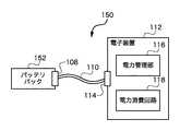
図1Bは本発明の別の実施例の電力供給システム150を示すブロック図である。電力供給システム150は、電源アダプタ102がバッテリパック152に置き換わることを除いて、図1Aに示す電力供給システム100とほぼ同じである。バッテリパック152はDC電力を供給する。周辺ケーブル110は、バッテリパック152から電子装置112にDC電力を供給するために使用される。電子装置112は、周辺ケーブル110によって供給されるDC電力を消費することができる。しかし、図1Aの電源アダプタ102と同様、バッテリパック152は、ある限られた電力を供給するように設計されている。それ故、電子回路112の適正な設計は、バッテリパック152によって利用可能になる、ある限られた電力を電子回路112が大事にすることを、規定すべきだろう。しかし、バッテリパック152の利用可能な電力は、バッテリパック152に設けられたバッテリの種類と数量によって異なる。電力管理装置116は、バッテリパック152の利用可能な電力を過剰消費しないように、電子装置112内の電力消費回路118に作用することができる。それ故、限られた電力が異なる、異なるバッテリパックに接続された場合でも、電子装置112の動作の安定は維持される。電力管理部116は、通常、消費電力がバッテリパック152によって利用可能になる、ある限られた電力を超えないように、例えば、電力消費回路118の様々な回路の使用を、無効にする、制限する、または、順にすることができる。バッテリパック152が未接続の場合に電力を供給するため、あるいは、バッテリパック152が接続されている場合に(必要があれば)補助電力を供給するために、電子装置112内にバッテリを設けることができる。 FIG. 1B is a block diagram showing a
図2Aは本発明の一実施例の電源アダプタ200を示すブロック図である。電源アダプタ200は、例えば、図1Aに示す電源アダプタ102としての使用に適している。 FIG. 2A is a block diagram showing a
電源アダプタ200はAC/DCコンバータ202と利用可能電力指示部204を含む。例えば、図1Aに示すように、AC/DCコンバータ202は、ACアウトレットからACプラグ104および電源コード106を介して、AC電力を受け取ることができる。そして、AC電力は、AC/DCコンバータ202によって、DC電力に変換される。そして、DC電力は、周辺コネクタ206の電力線に結合される。接地線も周辺コネクタ206に接続される。利用可能電力指示部204は、DC電力と接地線に接続する。利用可能電力指示部204は、利用可能電力の指示(indication)を提供する。利用可能電力の指示は、電源アダプタ200が提供する利用可能な電力を示す。利用可能電力指示部204が提供する利用可能電力の指示は、図2Aに示すデータ線DPとDMなど、周辺コネクタ206のデータ線に結合される。 The
利用可能電力指示部204は、多様な異なる方法によって実装可能である。一実施例において、利用可能電力指示部204は、アナログ電圧レベルを周辺コネクタ206のデータ線DPとDMに接続する。電圧レベルは、電源アダプタ200によって供給される利用可能な電力を示すために使用可能である。データ線上の電圧レベルは、直接または差動方式で使用される。別の実施例においては、データ線を介する信号方式(signaling)を利用することができる。信号方式は、ディジタル信号に関係するか、周波数またはパルス幅変調方式を用いる信号に関係することが可能である。 The available
図2Bは本発明の一実施例のバッテリパック250を示すブロック図である。バッテリパック250は、例えば、図1Bに示すバッテリパック152としての使用に適している。 FIG. 2B is a block diagram showing a
バッテリパック250は、一つ以上のバッテリ252とDC/DCレギュレータ254を含む。DC/DCレギュレータ254は、一つ以上のバッテリ252が供給するDC電力の調整に作用する。バッテリパック250は、さらに利用可能電力指示部204を含む。そして、DC電力は、周辺コネクタ206の電力線に結合される。接地線は、一つ以上のバッテリ252と周辺コネクタ206に接続される。前述したように、利用可能電力指示部204は、利用可能電力の指示を提供する。この実施例において、利用可能電力の指示は、バッテリパック250が提供する利用可能な電力を示す。利用可能電力指示部204が提供する利用可能電力の指示は、図2Bに示すデータ線DPとDMなど、周辺コネクタ206のデータ線に結合される。 The
データ線DPとDMにアナログ電圧レベルを適用する利用可能電力指示部204を実装する場合、利用可能電力指示部204は抵抗器配列(resistor arrangement)によって実現可能である。図3A〜3Cは、本発明のある実施例に従い、利用可能電力指示部204を実装するために利用可能な、異なる、代表的な抵抗器配列を示す。 When the available
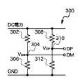
図3Aは本発明の一実施例の抵抗器配列300を示す概略図である。抵抗器配列300は、DC電力と第一のノード304の間に連結された第一の抵抗器302を含む。第二の抵抗器306は、第一のノード304と接地電位(GND)の間に連結される。第三の抵抗器308は、DC電力と第二のノード310の間に連結される。第四の抵抗器312は、第二のノード310とGNDの間に連結される。データ線DPは第二のノード310に接続され、データ線DMは第一のノード304に接続される。それ故、第二のノード310に現れる電圧VDPはデータ線DPに送出され、第一のノード304に現れる電圧VDMはデータ線DMに送出される。FIG. 3A is a schematic diagram illustrating a
図3Bは本発明の別の実施例の抵抗器配列320を示す。抵抗器配列320は、DC電力と第一のノード324の間に連結された第一の抵抗器322を含む。第二の抵抗器326は、第一のノード324と第二のノード328の間に連結される。第三の抵抗器330は、第二のノード328とGNDの間に連結される。電圧VDPがデータ回線DPに送出されるように、データ線DPは第一のノード324に接続される。電圧VDMをデータ線DMに供給するために、データ線DMは第二のノード328に接続される。FIG. 3B shows a
図3Cは本発明の別の実施例の抵抗器配列340を示す。第一の抵抗器342は、DC電力と第一のノード344の間に連結される。第二の抵抗器346は、第一のノード344と第二のノード348の間に連結される。第三の抵抗器350は、第二のノード348とGNDの間に連結される。電圧VDMをデータ線DMに供給するために、データ線DMは第一のノード344に接続される。電圧VDPをデータ線DPに供給するために、データ線DPは第二のノード348に接続される。FIG. 3C shows a
なお、データ線DPとDMに結合される電圧は、直接または差動方式で使用可能である。例えば、VDPM=VDP-VDMのような差分電圧を利用することができる。差分電圧を使用する利点は、検出することが可能な、利用可能な電力レベルの段階数が増える(例えば倍増する)ことである。また、図3Bに示す抵抗器配列320は、常に、電圧VDPが電圧VDMより大きくなることを保証する。これに対し、図3Cの抵抗器配列340は、常に、電圧VDMが電圧VDPより大きくなることを保証する。それ故、抵抗器配列320と340は、とくに、差分電圧法に適合する。The voltage coupled to the data lines DP and DM can be used directly or in a differential manner. For example, a differential voltage such as VDPM = VDP -VDM can be used. The advantage of using differential voltage is that the number of available power level steps that can be detected is increased (eg, doubled). Also, the
本発明の一実施例によれば、データ線DPとDMに現れる電圧VDPとVDMはそれぞれ、常に、電子装置112によって「高い」と見做されるべきである。つまり、これらの電圧レベルは、データ線の電圧が「高い」か「低い」かを判定するために使用される最低の高レベル電圧より大きい。それ故、これらの電圧は「高い」だが、高レベル電圧の複数の段階を提供するために、これらの電圧は最低の高レベルを異なる量だけ超えることができる。これら異なる段階は、電子装置112に対して、電源アダプタ102が提供する利用可能な電力の特定の量の知らせる(signal)ことに利用可能である。According to one embodiment of the present invention, the voltages VDP and VDM appearing on the data lines DP and DM, respectively, should always be considered “high” by the
図4Aは高電圧レベルと利用可能な電力の代表的な相関を規定するテーブル400を示す。図4Aに示すテーブル400が示すように、高電圧レベルH1は、対応する電源の利用可能な電力が0.5Wであることを示す。電源は、電源アダプタまたはバッテリパックでよい。高電圧レベルH2は、対応する電源の利用可能な電力が1Wであることを示す。高電圧レベルH3は、対応する電源の利用可能な電力が3.0Wであることを示す。さらに、通常、n番目の高電圧レベル(Hn)は、対応する電源の利用可能な電力が8.0Wであることを示す。高電圧レベルH1、H22、H3、…、Hnは実装に依存して変わるが、これら電圧レベルはすべて「高い」レベルである。例えば、周辺バスが2.0〜3.3Vを「高い」と見做す場合、高電圧レベルH1、H22、H3、…、Hnは、2.0Vから3.3Vの範囲内の別個の重複しない電圧または電圧範囲を表す。FIG. 4A shows a table 400 defining a typical correlation between high voltage levels and available power. As shown in the table 400 shown in FIG. 4A, the high voltage level H1 indicates that the available power of the corresponding power supply is 0.5 W. The power source may be a power adapter or a battery pack. High voltage level H2 indicates that the available power of the corresponding power is 1W. High voltage level H3 indicates that the available power of the corresponding power is 3.0 W. Furthermore, typically, the nth high voltage level (Hn ) indicates that the available power of the corresponding power supply is 8.0 W. The high voltage levels H1 ,
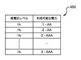
図4Bは高電圧レベルと利用可能な電力の代表的な相関を規定するテーブル450を示す。テーブル450は、電源がバッテリパックの場合の使用に適する。テーブル450は、利用可能な電力の指示を間接的に提供するバッテリパックの特性を示す。図4Bに示すテーブル450が示すように、高電圧レベルH1は、対応するバッテリパックが一つのAAバッテリを有することを示す。高電圧レベルH2は、対応するバッテリパックが二つのAAバッテリを有することを示す。高電圧レベルH3は、対応するバッテリパックが二つのAAAバッテリを有することを示す。さらに、通常、n番目の高電圧レベル(Hn)は、対応するバッテリパックが三つのAAAバッテリを有することを示す。高電圧レベルH1、H22、H3、…、Hnは実装に依存して変わるが、これら電圧レベルはすべて「高い」レベルである。FIG. 4B shows a table 450 defining a typical correlation between high voltage levels and available power. The table 450 is suitable for use when the power source is a battery pack. Table 450 shows the characteristics of the battery pack that indirectly provides an indication of available power. As the table 450 shown in FIG. 4B, the high voltage level H1 indicates that the corresponding battery pack has one AA battery. High voltage level H2 indicates that the corresponding battery pack has two AA batteries. High voltage level H3 indicates that the corresponding battery pack has two AAA batteries. Further, typically, the nth high voltage level (Hn ) indicates that the corresponding battery pack has three AAA batteries. The high voltage levels H1 ,
他の実施例において、電圧差(例えばVDPM=VDP-VDM)の符号(正または負)は、異なる電源の識別に利用することができる。例えば、電圧差が正ならば、電源は電源アダプタと見做すことができる。一方、電圧差が負ならば、電源はバッテリパックと見做すことができる。そして、前述したように、電力利用可能度のレベルを直接または間接的に表すために、電圧差の大小を利用することができる。In other embodiments, the sign (positive or negative) of the voltage difference (eg, VDPM = VDP −VDM ) can be used to identify different power supplies. For example, if the voltage difference is positive, the power source can be considered a power adapter. On the other hand, if the voltage difference is negative, the power source can be regarded as a battery pack. As described above, the magnitude of the voltage difference can be used to directly or indirectly represent the level of power availability.
図5は本発明の一実施例による電子装置500を示すブロック図である。電子装置500は、例えば、図1Aと1Bに示す電子装置112を代表することができる。 FIG. 5 is a block diagram illustrating an
電子装置500は、周辺コネクタ502に連結するか、周辺コネクタ502を含む。周辺コネクタ502は、DC電力線、データDP線、データDM線および接地(GND)線に接続される。これら線はバスインタフェイス504に供給(supply)される。バスインタフェイス504は、電力を受け取り、および/または、周辺バスを介したデータ送受信に参加するために、電子装置500を作動させる。本発明は、主に周辺バスを介した電力の受け取りに関係するから、以下では、主に、電子装置500における周辺バスを介した電力の受け取りと、安定動作を保証するための電力利用の管理を説明する。 The
電子装置500は、さらにアナログ/ディジタル変換回路506を含む。アナログ/ディジタル変換回路506はデータ線DPとDMに接続する。アナログ/ディジタル変換回路506は、データ線DPとDMのアナログ電圧レベルを、コントローラ508に供給するディジタル電圧レベルに変換する。とくに、ディジタル電圧レベルは利用可能電力検出部510に供給される。本実施例において、利用可能電力検出部510はコントローラ508内に設けられている。例えば、コントローラ508は、通常、マイクロプロセッサ、カスタムIC(例えばASIC)またはプログラム済みのプログラマブルICのような集積回路である。利用可能電力検出部510は、利用可能な電力レベルを判定するために、ディジタル電圧レベルを検査する。利用可能な電力レベルは、電源から周辺バスを介して電子装置500が利用可能な電力を表す。利用可能な電力レベルが判定されると、利用可能な電力レベルは電力管理部512に提供される。本実施例において、電力管理部512はコントローラ508内に設けられている。電力管理部512は、電子装置500が周辺バスを介して引く電力が、通常、電源の利用可能な電力を超えないように、電子装置500の動作アクティビティを制御するように作用する。これに関して、電力管理部512は、電子装置500の電力消費を管理するために、コントローラ508または他の電力消費回路514に動作を延期させるか、シーケンス動作を実行させるか、動作を回避させるだろう。
通常、電子装置500は、バッテリ駆動の装置(battery-powered device)であり、電子装置500内の再充電可能なバッテリは、周辺バスを介して供給される電力によって充電可能である。それ故、充電動作は、電子装置500内の他の回路が利用可能な電力に影響するだろう。さらに、バッテリが十分に充電されている限り、電子装置500の動作アクティビティによって周辺バスを介して電源から供給される利用可能な電力を超えた場合、バッテリは、電子装置500が消費する追加電力を供給することができるだろう。他の電力消費回路514の例は、実装に依存して多岐に亘る。しかし、他の電力消費回路514の幾つかの例は、ディスクドライブ、バッテリ充電回路、メモリデバイス(例えばRAM、ROM)、バッテリモニタおよびディスプレイなどである。 Typically, the
図5に示す電子装置500の実施例において、利用可能電力検出部510と電力管理部512はコントローラ508内に設けられている。しかし、利用可能電力検出部510および電力管理部512は、コントローラ508内に設ける必要はなく、別個の構成要素でも、一体に統合されていてもよいと認識されるべきである。 In the embodiment of the
図6は本発明の一実施例のアナログ/ディジタル変換回路600を示す概略図である。アナログ/ディジタル変換回路600は、例えば、図5に示されるアナログ/ディジタル変換回路506としての使用に適している。アナログ/ディジタル変換回路600は、データ線DPのアナログ電圧をnビットのディジタル出力に変換するために、抵抗器602と604、および、アナログ/ディジタル変換器(ADC)606を含む。同様に、抵抗器608と610、および、ADC 612は、データ線DMのアナログ電圧をnビットのディジタル出力に変換する。 FIG. 6 is a schematic diagram showing an analog /
図5に示すアナログ/ディジタル変換回路506の別の実施例においては、スイッチまたはマルチプレクサ、並びに、アナログ/ディジタル変換回路600のごく一部を使用することで、データ線DPとDMの変換回路の共用が可能だろう。例えば、スイッチまたはマルチプレクサがデータ線DMとDPの一方と抵抗器602を選択的に接続すれば、ADC 606の出力はデータ線DMまたはデータ線DPのディジタル電圧になる。従って、抵抗器608と610、および、ADC 612は不要になる。 In another embodiment of the analog /
図7は本発明の一実施例の電力管理システム700を示すブロック図である。電力管理システム700は、本発明の一実施例の電力管理部512のような電力管理装置の代表的な動作を描写する。電力管理システム700は電子装置の一部を代表する。 FIG. 7 is a block diagram showing a
電力管理システム700は電力管理部702を含む。電力管理部702は、利用可能電力検出部510のような利用可能電力検出器から利用可能な電力レベル(APL)を受信する。電力管理部702は、利用可能な電力レベルに基づき、電子回路の動作を制御するように作用する。図7に示すように、電力管理システム700は、バッテリ704とバッテリモニタ706に連結可能である。バッテリモニタ706は、バッテリ充電レベル(BCL)を監視し、バッテリ充電レベルを電力管理部702に提供することができる。その結果、電力管理部702は、さらに、バッテリ充電レベルに基づき電子回路の動作を制御することができる。言い換えれば、電力管理部702は、利用可能な電力レベルおよび/またはバッテリ充電レベルに基づき、電子装置の電力消費を管理することができる。 The
電源によって電子装置に供給される電力は、バッテリ充電回路708を介してバッテリ704に結合される。電源の利用可能な電力をバッテリ704の充電に利用するように、または、電源の利用可能な電力をバッテリ704の充電に利用することを防ぐように、電力管理部702によってバッテリ充電回路708を制御することができる。電力管理システム700は、さらに、電子装置と協働する他の電力消費回路710を含む。他の電力消費回路710は、実装に依存して多種多様である。しかし、一部またはすべての電力消費回路710は、電力管理部702によって制御可能である。例えば、電力管理部702は、ある回路の使用を制限する、異なるシーケンスで回路を始動させる、回路の使用を変更する、などができる。その場合、電力管理部702は、利用可能な電力レベルだけではなく、バッテリ充電レベルも利用することができる。図7に示すように、バッテリからの電力PBATは、電源からの電力PINと組み合わされて、装置電力POUTを生む。装置電力POUTは、少なくとも電力管理部702、バッテリモニタ706および他の電力消費回路710に供給される。それ故、電力消費は電力管理部702によって管理されてはいるが、電力の差をバッテリPBATから利用可能であれば、電子装置によって引かれる電力は、電源によって電子装置に供給される電力、つまり電力PINを超えることができる。The power supplied to the electronic device by the power source is coupled to the
図8は本発明の一実施例の利用可能電力処理800を示すフローチャートである。利用可能電力処理800は、例えば、図1Aと1Bに示す電子装置112、または、図5に示す電子装置500のような、電子装置によって実行される。 FIG. 8 is a flowchart illustrating
利用可能電力処理800は、周辺バスが検出されたか否かを判定する決定802によって開始される。この場合、電子装置は、ホスト装置と電子装置の間の周辺バスの連結を、監視するか、通知を受けることができる。一実施例において、電子装置の周辺コネクタの電力線(例えばDC電力)において正電源(例えば、5V)の存在が検出されたら、電子装置により周辺バスの存在が検出されたと見做すことができる。決定802が周辺バスは検出されなかったと判定した場合、利用可能電力処理800は、周辺バスの検出を待つ。言い換えれば、周辺バスが検出されて初めて、利用可能電力処理800は開始されるか、引き起こされると見做すことができる。 The
決定802が周辺バスは検出されたと判定すると、周辺バスのバスデータ線から電圧レベルが読み取られる(804)。例えば、図5に示すようなデータ線DPとDMから電圧レベルを読み取ることができる。次に、決定806は、ホスト装置が電源か否かを判定する。検出される周辺バスは、電源やコンピュータを含む様々な異なる装置(例えばホスト装置)に連結可能である。一実施例において、バスデータ線の電圧レベルはホスト装置の種類を知らせる(signal)ことができる。例えば、本発明は、電源であるホスト装置との組み合わせに使用することが、とくに適している。とくに、バスデータ線の電圧レベルは、ホスト装置が電源であることを知らせることができる。一つの実装において、バスデータ線の「高い」電圧レベルは、電源の存在を知らせることができる。 If
何れにしても、決定806がホスト装置は電源ではないと判定した場合、他の標準処理808の実行が可能である。例えば、ホスト装置がコンピュータであれば、他の標準処理808は、コンピュータと電子装置の間のデータ交換を促進する動作に関係するだろう。 In any case, if the
他方、決定806がホスト装置は電源であると判定した場合、電源の利用可能な電力レベルが判定される(810)。一実施例において、さらに、バスデータ線の電圧レベルを検査することで、電源の利用可能な電力レベルを判定することができる(810)。つまり、バスデータ線の電圧レベルは、電源の利用可能な電力レベルを知らせることができる。例えば、図4Aに関して説明したように、バスデータ線の電圧レベルを複数の「高い」電圧レベルH1、H2、H3、…、Hnに分類することができ、各電圧レベルは、電源が供給する異なる利用可能な電力レベル、つまり0.5W、1W、3W、…、8Wに対応すると見做すことができる。On the other hand, if the
利用可能な電力レベルが判定された(810)後、判定された利用可能な電力レベルに従い、電子装置の電力利用を管理することができる(812)。すなわち、電子装置の動作中、判定された利用可能な電力レベルに応じて動作または機能が変化するように、電力利用を制御または管理することができる。 After the available power level is determined (810), the power usage of the electronic device can be managed according to the determined available power level (812). That is, power usage can be controlled or managed so that during operation of the electronic device, the operation or function changes according to the determined available power level.
次に、ブロック808と812に続く決定814は、周辺バスの接続が解除されたか否かを判定する。決定814が周辺バスの接続は解除されていないと判定した場合、ブロック812を繰り返して、電子装置の電力利用を引き続き管理するために、処理はリターンする。あるいは、決定814が周辺バスの接続が解除されたと判定した場合、決定802とそれに続くブロックを繰り返すために、処理はリターンする。従って、電子装置は、その後、周辺バスが電子装置に接続された場合に利用可能電力処理800を再び実行することができる。 Next, a
とくに電力が集中する動作の一種類は、電子装置の初期スタートアップを伴う起動処理である。通常、起動処理を実行する電子装置は、電子装置のオペレーティングシステムが使用するか、オペレーティングシステムを立ち上げるために使用されるプログラムコードが格納されたディスクドライブ装置を含むだろう。 One type of operation in which power is particularly concentrated is a startup process that involves an initial startup of an electronic device. Typically, the electronic device that performs the boot process will include a disk drive device that stores program code that is used by the operating system of the electronic device or that is used to start up the operating system.
図9は本発明の一実施例の起動処理900を示すフローチャートである。電子装置は、動作用に電子装置を始動するために、起動処理900を実行することができる。 FIG. 9 is a flowchart showing the
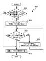
起動処理900は、判定された利用可能な電力レベルが最小起動電力レベル以上か否かを判定する決定902によって開始される。例えば、判定された利用可能な電力レベルは、図8に示す利用可能電力処理のブロック810で判定することができる。決定902が、判定された(電源の)利用可能な電力レベルは最小起動電力レベル以上ではないと判定した場合、立ち上げに適切な時間か否かを判定するために別の処理が実行される。とくに、バッテリの充電レベルが読み取られる(904)。そして、決定906は、バッテリ充電レベルが最小充電レベル以上か否かを判定する。決定906がバッテリ充電レベルは最小充電レベル以上ではないと判定した場合、バッテリは充電され、起動シーケンスは延期される(908)。ブロック908に続き、決定906を繰り返して、バッテリ充電レベルと最小充電レベルを再び比較するために、起動処理900はリターンする。決定906がバッテリ充電レベルは最小充電レベル以上と判定すると、起動処理900は、起動シーケンスの実行を許可する(910)。 The
他方、決定902が判定された利用可能な電力レベルは最小起動電力レベル以上と判定した場合、起動シーケンスは直接実行可能である(910)。従って、判定された、電源が供給する利用可能な電力レベルが、起動シーケンス中に電子装置を適正に動作させるために必要な最小起動電力レベルを超えると見做される場合、起動処理900は、起動シーケンスの早速の実行を許可する。しかし、判定された、電源が供給する利用可能な電力レベルが最小起動電力レベル以上ではない場合、電子装置のバッテリから追加電力を引き出す必要があるだろう。それ故、決定906は、起動シーケンスの実行(910)が可能になる前に、バッテリが少なくとも最小充電レベルを有することを保証する。起動シーケンスの実行(910)に続いて、起動処理900は完了する。 On the other hand, if the available power level determined by
ここで説明される電子装置は、メディアアイテムをプレイ(表示を含む)可能なメディアプレーヤでよい。メディアアイテムは、オーディオアイテム(例えばオーディオファイルまたは楽曲(songs))、ビデオ(例えばムービ)、あるいは、画像(例えば写真)に関連する。 The electronic device described herein may be a media player capable of playing (including displaying) media items. A media item is associated with an audio item (eg, an audio file or songs), a video (eg, a movie), or an image (eg, a photo).
図10は本発明とともに使用するのに適したメディアプレーヤ1000を示すブロック図である。メディアプレーヤ1000は、図1Aと1Bの電子装置112、または、図5の電子装置500の回路を含むことが可能で、および/または、図8と9を参照して説明した動作を実行可能である。 FIG. 10 is a block diagram illustrating a
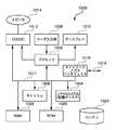
メディアプレーヤ1000は、メディアプレーヤ1000の動作全体を制御するマイクロプロセッサまたはコントローラに関連するプロセッサ1002を含む。メディアプレーヤ1000は、メディアアイテムに関連するメディアデータをファイルシステム1004とキャッシュ1006に格納する。ファイルシステム1004は、通常、一枚の記憶ディスクまたは複数のディスクである。通常、ファイルシステム1004は、メディアプレーヤ1000に対して大容量記憶能力を提供する。しかし、ファイルシステム1004へのアクセス時間は比較的遅いため、メディアプレーヤ1000は、さらにキャッシュ1006を含むことができる。キャッシュ1006は、例えば、半導体メモリのランダムアクセスメモリ(RAM)である。キャッシュ1006の相対アクセス時間は、ファイルシステム1004より、かなり短い。しかし、キャッシュ1006は、ファイルシステム1004のような大きな記憶容量をもたない。さらに、ファイルシステム1004は、アクティブの場合、キャッシュ1006よりも多くの電力を消費する。メディアプレーヤ1000が(図示しない)バッテリ駆動のポータブルメディアプレーヤの場合、電力消費はしばしば重大な関心事である。メディアプレーヤ1000は、さらに、RAM 1020と読み取り専用メモリ(ROM)1022を含む。ROM 1022は、実行されるべきプログラム、ユーティリティまたは処理を不揮発に格納することができる。RAM 1020は、キャッシュ1006など、揮発性のデータ格納を提供する。
メディアプレーヤ1000は、さらに、ユーザとメディアプレーヤ1000の対話を可能にするユーザ入力部1008を含む。例えば、ユーザ入力部1008は、ボタン、キーパッド、ダイアルなど、多様な形態をとることができる。さらに、メディアプレーヤ1000は、プロセッサ1002により制御可能で、ユーザに情報を表示するディスプレイ1010(画面表示)を含む。データバス1011は、少なくともファイルシステム1004、キャッシュ1006、プロセッサ1002およびCODEC 1012の間のデータ転送を促進することができる。 The
一実施例において、メディアプレーヤ1000は、複数のメディアアイテム(例えば楽曲)をファイルシステム1004に格納する役割を果たす。ユーザが特定のメディアアイテムをメディアプレーヤにプレイさせたいと望んだ場合、利用可能なメディアアイテムのリストがディスプレイ1010に表示される。そして、ユーザは、ユーザ入力部1008を使用して、利用可能なメディアアイテムの一つを選択することができる。プロセッサ1002は、特定のメディアアイテムの選択を受信すると、その特定のメディアアイテムのメディアデータ(例えばオーディオファイル)を符号化復号器(CODEC)1012に供給する。そして、CODEC 1012は、スピーカ1014用のアナログ出力信号を生成する。スピーカ1014は、メディアプレーヤ1000内のスピーカでも、メディアプレーヤ1000外のスピーカでもよい。例えば、メディアプレーヤ1000に接続するヘッドホンまたはイヤホンが外部スピーカと考えられる。 In one embodiment,
メディアプレーヤ1000は、さらに、データリンク1018に接続するバスインタフェイス1016を含む。データリンク1018は、メディアプレーヤ1000がホスト装置(例えばホストコンピュータまたは電源)に連結することを可能にする。データリンク1018は、メディアプレーヤ1000に電力を供給することもできる。
本発明の様々な面、実施例、実装形態または特徴は、個別に使用しても、任意の組み合わせで使用してもよい。 Various aspects, embodiments, implementations or features of the invention may be used individually or in any combination.
本発明は、ハードウェア、ソフトウェアまたはハードウェアとソフトウェアの組み合わせによって実装されることが好ましい。ソフトウェアは、コンピュータが読み取り可能な媒体上のコンピュータが読み取り可能なコードとして実現することができる。コンピュータが読み取り可能な媒体は、データを格納可能で、その後、コンピュータシステムがデータを読取可能な任意のデータ格納デバイスである。コンピュータが読み取り可能な媒体の例は、読出専用メモリ、ランダムアクセスメモリ、CD-ROM、DVD、磁気テープ、光データ記憶デバイスおよび搬送波などがある。コンピュータが読み取り可能なコードを分散方式で格納し、かつ、実行するために、ネットワーク接続されたコンピュータシステムを介して、コンピュータが読み取り可能な媒体を分散させることも可能である。 The present invention is preferably implemented by hardware, software or a combination of hardware and software. The software can be implemented as computer readable code on a computer readable medium. The computer readable medium is any data storage device that can store data, which can thereafter be read by a computer system. Examples of computer readable media include read only memory, random access memory, CD-ROM, DVD, magnetic tape, optical data storage device and carrier wave. It is also possible to distribute computer readable media through a networked computer system for storing and executing computer readable code in a distributed fashion.
本発明の利点は多数ある。異なる面、実施例または実装形態により、次に挙げる利点のうち一つ以上がもたらされるだろう。本発明の一つの利点は、ポータブルメディア装置は、装置の周辺ポートに電源が接続されているか否か、および、接続されていれば、電源から周辺ポートを介して引くことが可能な電力を容易かつ迅速に判定することができることである。本発明の別の利点は、安定した確実な動作のために、ポータブルメディア装置の電力利用を、利用可能な電力に依存させられることである。 The advantages of the present invention are numerous. Different aspects, examples or implementations may provide one or more of the following advantages. One advantage of the present invention is that a portable media device facilitates whether or not a power source is connected to the peripheral port of the device, and if so, the power that can be drawn from the power source through the peripheral port. And it can be determined quickly. Another advantage of the present invention is that the power usage of the portable media device can be made dependent on the available power for stable and reliable operation.
本発明の多くの特徴および利点は、以上の説明から明らかであるから、添付する請求の範囲により、本発明のそのような特徴および利点のすべてを包含することが意図される。さらに、多くの変形および変更は当業者に容易に着想され、本発明は、図示かつ説明された構成および動作に厳密に限定されるべきではない。それ故、適切な変形および等価の構成はすべて、本発明の範囲に入ると見做してもよい。 Since many features and advantages of the invention will be apparent from the foregoing description, it is intended by the appended claims to cover all such features and advantages of the invention. Further, many variations and modifications will readily occur to those skilled in the art, and the present invention should not be strictly limited to the arrangement and operation shown and described. Therefore, all suitable variations and equivalent configurations may be considered as falling within the scope of the present invention.
Claims (32)
Translated fromJapanese前記バスインタフェイスに接続する利用可能電力検出器と、
電力消費回路と、
前記利用可能電力検出器と前記電力消費回路に接続する電力管理部とを有し、
前記バスコネクタを介して前記バスインタフェイスに電源が接続された場合、前記利用可能電力検出器は、前記複数のディジタルデータ線の電圧値を取得し、前記取得した電圧値をディジタル値に変換し、前記ディジタル値を用いて前記電力線を介して前記電源から供給される利用可能な電力のレベルを検出し、
前記電力管理部は、前記利用可能な電力のレベルに基づき、前記電力消費回路の少なくとも一部による電力利用を管理することを特徴とする電気装置。A bus interface that connects to a bus connector that provides a power line, a ground line and a plurality ofdigital data lines;
An available power detector connected to the bus interface;
A power consumption circuit;
A power management unit connectedto the available power detector and the power consuming circuit;
When a power source is connected to the bus interface via the bus connector, the available power detector acquires voltage values of the plurality of digital data lines, and converts the acquired voltage values into digital values. Detecting the level of available power supplied from the power source via the power line using the digital value;
The power management unit manages power usage by at least a part of the power consuming circuit based on the level of available power.
少なくとも電力線と複数のディジタルデータ線を有し、接続されたホスト装置と協働する周辺バスと、前記電気装置の周辺コネクタの接続を検出し、
前記周辺バスと前記周辺コネクタの接続を検出すると、前記複数のディジタルデータ線のアナログ電圧レベルを読み取り、
前記読み取ったアナログ電圧レベルに基づき前記ホスト装置が電源か否かを判定し、
前記ホスト装置が電源の場合は、前記アナログ電圧レベルをディジタル値に変換し、前記ディジタル値を用いて前記ホスト装置の種類を識別することを特徴とする方法。A method for identifying ahost deviceconnected to a peripheral connector of an electrical device, comprising:
Detecting a connection between a peripheral bus having at least a power line and a plurality ofdigital data lines and cooperating with a connected host device and a peripheral connector of the electrical device;
Upon detecting the connectionbetween the peripheral busand the peripheral connector , theanalog voltage levels of theplurality of digital data lines are read,
Determining whether the host device is a power source based on the read analog voltage level;
When the host device is a power supply, the analog voltage level is converted into a digital value, andthe type of the host deviceis identifiedusing the digital value .
前記電源によって前記複数のディジタルデータ線に誘起されたアナログ電圧レベルを読み取り、
前記複数のディジタルデータ線から読み取ったアナログ電圧レベルをディジタル値に変換し、
前記ディジタル値に基づき、前記電源の電力利用可能度を判定することを特徴とする方法。A method for determining the power availability of a power source connected to an electrical device via a peripheral bus having at least a power line and a plurality ofdigital data lines,
Readinganalog voltage levels induced in theplurality of digital data lines by the power source;
Converting analog voltage levels read from the plurality of digital data lines into digital values;
Method characterized in that on the basis of thedigital values, determining thepower availabilityof the power supply.
少なくとも電力線と複数のディジタルデータ線を有する周辺バスと、前記電気装置の周辺コネクタの接続を検出し、
前記周辺バスと前記周辺コネクタの接続を検出すると、前記複数のディジタルデータ線のアナログ電圧レベルを取得し、
前記アナログ電圧レベルをディジタル値に変換し、
前記ディジタル値に基づき、前記周辺バスを提供するホスト装置が電源アダプタか否かを判定し、
前記ホスト装置が電源アダプタであると判定すると、前記ディジタル値に基づき、前記電源アダプタから供給される利用可能な電力レベルを判定し、
前記電源アダプタから供給される利用可能な電力レベルに基づき、前記電気装置の電力利用を管理することを特徴とする方法。A method for managing power usage of an electrical device having aperipheral connector,
Detecting a connection between a peripheral bus having at least a power line and a plurality ofdigital data lines, and aperipheral connector of the electrical device;
Upon detecting the connectionbetween the peripheral busand the peripheral connector , theanalog voltage levels of theplurality of digital data lines areacquired ,
Converting the analog voltage level to a digital value;
Based on thedigital value , it is determined whether the host device providing the peripheral bus is a poweradapter ,
When determining that the host device is a poweradapter , based on thedigital value , determinean available power levelsupplied from the poweradapter ,
A method of managing power usage of the electrical device basedon an available power levelsupplied from the poweradapter .
少なくとも電力線と複数のディジタルデータ線を有する周辺バスと、前記電気装置の周辺コネクタの接続を検出し、
前記周辺バスと前記周辺コネクタの接続を検出すると、前記ディジタルデータ線のアナログ電圧レベルを取得し、
前記アナログ電圧レベルをディジタル値に変換し、
前記ディジタル値に基づき、前記周辺バスを提供するホスト装置がバッテリパックか否かを判定し、
前記ホスト装置がバッテリパックであると判定すると、前記ディジタル値に基づき、前記バッテリパックの利用可能な電力容量を判定し、
前記バッテリパックの利用可能な電力容量に基づき、前記電気装置の電力利用を管理することを特徴とする方法。A method for managing power usage of an electrical device having aperipheral connector,
Detecting a connection between a peripheral bus having at least a power line and a plurality ofdigital data lines, and aperipheral connector of the electrical device;
Upon detecting the connectionbetween the peripheral busand the peripheral connector , ananalog voltage level of thedigital data line isacquired ,
Converting the analog voltage level to a digital value;
Based on thedigital value , it is determined whether the host device providing the peripheral bus is a battery pack,
When determining that the host device is a battery pack, based on thedigital value , determine an available power capacity of the battery pack,
Managing the power usage of the electrical device based on the available power capacity of the battery pack.
Applications Claiming Priority (4)
| Application Number | Priority Date | Filing Date | Title |
|---|---|---|---|
| US58895904P | 2004-07-18 | 2004-07-18 | |
| US60895904P | 2004-10-08 | 2004-10-08 | |
| US11/031,288US7581119B2 (en) | 2004-07-18 | 2005-01-07 | Method and system for discovering a power source on a peripheral bus |
| PCT/US2005/024906WO2006019850A2 (en) | 2004-07-18 | 2005-07-12 | Method and system for discovering a power source on a peripheral bus |
Related Child Applications (1)
| Application Number | Title | Priority Date | Filing Date |
|---|---|---|---|
| JP2010153472ADivisionJP4695220B2 (en) | 2004-07-18 | 2010-07-05 | Power supply device and power supply method |
Publications (2)
| Publication Number | Publication Date |
|---|---|
| JP2008507062A JP2008507062A (en) | 2008-03-06 |
| JP4664362B2true JP4664362B2 (en) | 2011-04-06 |
Family
ID=35004185
Family Applications (2)
| Application Number | Title | Priority Date | Filing Date |
|---|---|---|---|
| JP2007522569AExpired - LifetimeJP4664362B2 (en) | 2004-07-18 | 2005-07-12 | Electrical device, method for identifying host device, method for determining power availability of power supply, and method for managing power usage of electrical device |
| JP2010153472AExpired - LifetimeJP4695220B2 (en) | 2004-07-18 | 2010-07-05 | Power supply device and power supply method |
Family Applications After (1)
| Application Number | Title | Priority Date | Filing Date |
|---|---|---|---|
| JP2010153472AExpired - LifetimeJP4695220B2 (en) | 2004-07-18 | 2010-07-05 | Power supply device and power supply method |
Country Status (6)
| Country | Link |
|---|---|
| US (3) | US7581119B2 (en) |
| EP (2) | EP1769313B1 (en) |
| JP (2) | JP4664362B2 (en) |
| KR (2) | KR100947697B1 (en) |
| CN (2) | CN100573417C (en) |
| WO (1) | WO2006019850A2 (en) |
Cited By (1)
| Publication number | Priority date | Publication date | Assignee | Title |
|---|---|---|---|---|
| US9153984B2 (en) | 2012-03-19 | 2015-10-06 | Renesas Electronics Corporation | Charging device |
Families Citing this family (84)
| Publication number | Priority date | Publication date | Assignee | Title |
|---|---|---|---|---|
| US7868486B2 (en) | 2004-01-15 | 2011-01-11 | Comarco Wireless Technologies, Inc | Power supply having source determination circuitry utilized to disable battery charging circuitry in powered device |
| US9153960B2 (en) | 2004-01-15 | 2015-10-06 | Comarco Wireless Technologies, Inc. | Power supply equipment utilizing interchangeable tips to provide power and a data signal to electronic devices |
| US7581119B2 (en)* | 2004-07-18 | 2009-08-25 | Apple Inc. | Method and system for discovering a power source on a peripheral bus |
| US20060082934A1 (en)* | 2004-10-15 | 2006-04-20 | Dell Products L.P. | Power adapter featuring multiple power outputs |
| US8090309B2 (en)* | 2004-10-27 | 2012-01-03 | Chestnut Hill Sound, Inc. | Entertainment system with unified content selection |
| US7885622B2 (en)* | 2004-10-27 | 2011-02-08 | Chestnut Hill Sound Inc. | Entertainment system with bandless tuning |
| US20190278560A1 (en) | 2004-10-27 | 2019-09-12 | Chestnut Hill Sound, Inc. | Media appliance with auxiliary source module docking and fail-safe alarm modes |
| JP2007068333A (en)* | 2005-08-31 | 2007-03-15 | Sony Corp | Power supply-dedicated device, terminal, power supply system, and power supply method |
| US20070079153A1 (en)* | 2005-10-05 | 2007-04-05 | Dell Products L.P. | Information handling system, current and voltage mode power adapter, and method of operation |
| US7653823B2 (en)* | 2006-03-20 | 2010-01-26 | Lenovo (Singapore) Pte. Ltd. | Method and apparatus for informing computer of power environment |
| US20100201308A1 (en)* | 2006-06-29 | 2010-08-12 | Nokia Corporation | Device and method for battery charging |
| DE102006036770A1 (en)* | 2006-08-07 | 2008-02-14 | Siemens Ag | Method for commissioning at least one field device |
| US20080053770A1 (en)* | 2006-08-31 | 2008-03-06 | Timothy Tynyk | Travel case for a portable electronic device |
| US7728558B2 (en)* | 2007-01-05 | 2010-06-01 | Apple Inc. | Systems and methods for selectively changing current limit of a battery controller |
| FR2913508B1 (en) | 2007-03-09 | 2009-07-24 | Archos Sa | DEVICE FOR FEEDING A PORTABLE ELECTRONIC DEVICE BY COMBINING ENTRY / EXIT PORTS OF AT LEAST ONE OTHER ELECTRONIC EQUIPMENT, SYSTEM, METHOD AND APPLICATION THEREOF. |
| WO2008120044A1 (en) | 2007-03-29 | 2008-10-09 | Nokia Corporation | Connection to a usb device |
| US7671559B2 (en) | 2007-07-31 | 2010-03-02 | Apple Inc. | Battery charging system and mobile and accessory devices |
| KR101339822B1 (en)* | 2007-10-15 | 2013-12-11 | 삼성전자주식회사 | Method for controlling device based on a kind of peripheral device and potable device using the same |
| US20090267570A1 (en)* | 2008-04-28 | 2009-10-29 | Nokia Corporation | Apparatus for providing boot-up capability signals and associated methods |
| TWI459190B (en)* | 2009-07-22 | 2014-11-01 | Htc Corp | Power supply device, portable electronic apparatus and related method for determining types of a power supply device |
| TWI398759B (en) | 2009-07-22 | 2013-06-11 | Htc Corp | Power supply device, portable electronic apparatus and related method for determining types of a power supply device |
| CN101989751B (en)* | 2009-07-30 | 2014-01-15 | 宏达国际电子股份有限公司 | Portable electronic device and related judgment method |
| DE102009036586B4 (en)* | 2009-08-07 | 2014-02-20 | Fm Marketing Gmbh | Wireless remote control |
| US8626932B2 (en)* | 2009-09-01 | 2014-01-07 | Apple Inc. | Device-dependent selection between modes for asymmetric serial protocols |
| US9130400B2 (en) | 2009-09-24 | 2015-09-08 | Apple Inc. | Multiport power converter with load detection capabilities |
| KR101667707B1 (en)* | 2009-10-22 | 2016-10-19 | 엘지전자 주식회사 | Mobile terminal and usb dedicated charger determinating method thereof |
| US8358100B2 (en)* | 2009-11-03 | 2013-01-22 | Maxim Integrated Products, Inc. | USB dedicated charger identification circuit |
| CN102301303B (en)* | 2009-12-28 | 2016-01-20 | 松下知识产权经营株式会社 | Electronic device and control method for electronic device |
| US8069356B2 (en)* | 2010-01-06 | 2011-11-29 | Apple Inc. | Accessory power management |
| US8350522B2 (en) | 2010-03-10 | 2013-01-08 | Apple Inc. | External power source voltage drop compensation for portable devices |
| US8717044B2 (en)* | 2010-04-23 | 2014-05-06 | Apple Inc. | Charging systems with direct charging port support and extended capabilities |
| EP2383860B1 (en)* | 2010-04-29 | 2019-11-27 | Giga-Byte Technology Co., Ltd. | Rapid charging apparatus |
| US9292066B2 (en) | 2010-04-30 | 2016-03-22 | Blackberry Limited | Configuring cable lines to provide data and power |
| EP2383630B1 (en)* | 2010-04-30 | 2018-09-26 | BlackBerry Limited | Configuring cable lines to provide data and power |
| US9336170B2 (en) | 2010-05-11 | 2016-05-10 | Mediatek Inc. | Universal serial bus device and charging and enumeration method |
| KR101771452B1 (en)* | 2010-08-23 | 2017-08-25 | 엘지전자 주식회사 | Mobile terminal and usb dedicated charger determinating method thereof |
| US8513955B2 (en)* | 2010-09-28 | 2013-08-20 | Tyco Electronics Corporation | SSL budgeting and coding system for lighting assembly |
| US9436479B2 (en)* | 2011-01-17 | 2016-09-06 | Qualcomm Incorporated | Booting a mobile electronic device with a low battery based on a dynamic boot threshold |
| KR101218359B1 (en)* | 2011-03-02 | 2013-01-03 | 삼성테크윈 주식회사 | Electric device comprising a movable battery-container |
| US8560031B2 (en) | 2011-03-16 | 2013-10-15 | David B. Barnett | Extending socket for portable media player |
| US8762746B1 (en)* | 2011-03-22 | 2014-06-24 | Amazon Technologies, Inc. | Power management in electronic devices |
| FR2974197B1 (en)* | 2011-04-14 | 2013-05-17 | Hongbing Zhang | POWER SUPPLY DEVICE FOR COMPUTER |
| EP2629173A4 (en)* | 2011-06-09 | 2013-12-18 | Huawei Device Co Ltd | Method and system for powering usb device |
| WO2011150888A2 (en)* | 2011-06-24 | 2011-12-08 | 华为终端有限公司 | Method for supplying power to wireless network terminal and wireless network terminal |
| JP5367030B2 (en)* | 2011-08-10 | 2013-12-11 | シャープ株式会社 | Electronic equipment and electronic equipment system |
| US8689022B2 (en) | 2011-08-30 | 2014-04-01 | Qualcomm Incorporated | Methods of and apparatus for controlling power drawn by an appliance through a USB port |
| CN103890743B (en)* | 2011-10-17 | 2018-01-19 | 英特尔公司 | The IO power managements of host computer control |
| CN102769320A (en)* | 2012-07-31 | 2012-11-07 | 徐州华夏电子有限公司 | Car charging device for iphone |
| JP2014056287A (en) | 2012-09-11 | 2014-03-27 | Ricoh Co Ltd | Electronic apparatus and method of determining power source device by electronic apparatus |
| US8760123B2 (en)* | 2012-10-29 | 2014-06-24 | Qualcomm Incorporated | High voltage dedicated charging port |
| US8745301B2 (en)* | 2012-10-29 | 2014-06-03 | Qualcomm Incorporated | High voltage dedicated charging port |
| KR200472137Y1 (en)* | 2012-11-09 | 2014-04-10 | 최규택 | Universal gender for charging mobile phone |
| TWI460964B (en)* | 2012-12-07 | 2014-11-11 | Pegatron Corp | Adapter and electronic device and method for detecting power of the adapter |
| JP6288913B2 (en)* | 2012-12-28 | 2018-03-07 | キヤノン株式会社 | Electronic device and program |
| EP2965416B1 (en) | 2013-03-06 | 2018-12-26 | Hewlett-Packard Development Company, L.P. | Power supply voltage and load consumption control |
| US10162399B2 (en) | 2013-03-06 | 2018-12-25 | Hewlett-Packard Development Company, L.P. | Power supply voltage and load consumption control |
| US9312707B2 (en)* | 2013-05-10 | 2016-04-12 | S P Technologies LLC | Portable compact multiple-outlet power supply with circuit for supplying device-specific charging profiles to mobile telephones |
| CN104810868B (en)* | 2014-01-24 | 2017-05-10 | 华硕电脑股份有限公司 | Charging system and charging method thereof |
| JP5922165B2 (en)* | 2014-02-21 | 2016-05-24 | ホシデン株式会社 | Charging holder |
| US9553341B2 (en) | 2014-02-25 | 2017-01-24 | Motorola Solutions, Inc. | Method and apparatus for controlling access to a logic circuit in a battery by multiple components connected to the battery |
| US10355505B2 (en)* | 2014-03-10 | 2019-07-16 | Dell Products L.P. | Method for adapter over-current-protection (OCP) protection and user warning |
| CN109308111B (en)* | 2014-05-28 | 2022-03-01 | 精工爱普生株式会社 | Electronic device |
| US9588563B2 (en) | 2014-05-30 | 2017-03-07 | Apple Inc. | Protocol for managing a controllable power adapter accessory |
| US9766674B2 (en)* | 2014-06-27 | 2017-09-19 | Intel Corporation | USB power delivery controller sharing |
| US9634502B2 (en)* | 2014-08-20 | 2017-04-25 | Qualcomm Incorporated | Fast battery charging through digital feedback |
| TWI547952B (en)* | 2014-10-07 | 2016-09-01 | 新唐科技股份有限公司 | Controlling device, controlled device, and operating method |
| CN105630124A (en)* | 2014-12-01 | 2016-06-01 | 鸿富锦精密工业(武汉)有限公司 | Electronic equipment interface switching device |
| US10234919B2 (en) | 2015-09-21 | 2019-03-19 | Microsoft Technology Licensing, Llc | Accessory-based power distribution |
| US9690346B1 (en)* | 2015-10-30 | 2017-06-27 | Seagate Technology Llc | Load sharing across multiple voltage supplies |
| AT517928A2 (en)* | 2015-11-06 | 2017-05-15 | Keba Ag | Control system for electrically controlled systems |
| US9800703B2 (en) | 2015-11-23 | 2017-10-24 | TecTide Group, LLC | Handling apparatus for portable electronic devices |
| US10666070B2 (en) | 2016-01-07 | 2020-05-26 | Fairchild Semiconductor Corporation | Battery charge termination voltage reduction |
| KR102657052B1 (en)* | 2016-04-12 | 2024-04-15 | 삼성전자주식회사 | Method for charging battery and electronic apparatus |
| JP6763224B2 (en)* | 2016-07-20 | 2020-09-30 | 株式会社リコー | Image forming device and control device |
| US10054259B2 (en) | 2016-08-17 | 2018-08-21 | Popsockets Llc | Expanding socket accessory for mobile electronic device |
| KR102597036B1 (en) | 2016-10-11 | 2023-11-02 | 삼성전자주식회사 | electronic device having a dual-display and operating method thereof |
| US10459502B2 (en) | 2016-10-21 | 2019-10-29 | Seagate Technology Llc | Adaptive charge leveling in a data storage device |
| EP3367210A1 (en)* | 2017-02-24 | 2018-08-29 | Thomson Licensing | Method for operating a device and corresponding device, system, computer readable program product and computer readable storage medium |
| US10447052B2 (en)* | 2017-03-23 | 2019-10-15 | Intel Corporation | Apparatus, method, and system for dynamically controlling current and/or voltage profiles |
| CN110165725B (en)* | 2019-04-26 | 2021-05-11 | 华为技术有限公司 | Wireless charging method, receiver, terminal device and charger |
| CN110286731A (en)* | 2019-06-30 | 2019-09-27 | 联想(北京)有限公司 | A kind of information processing method and electronic equipment |
| CA3100782A1 (en)* | 2019-11-27 | 2021-05-27 | Bombardier Inc. | Methods and systems for operating an auxiliary power unit |
| CN119278420A (en)* | 2022-07-08 | 2025-01-07 | 雷蛇(亚太)私人有限公司 | Bus-powered device |
| EP4633129A1 (en)* | 2022-12-12 | 2025-10-15 | LG Electronics Inc. | Display device and power supply control method thereof |
Family Cites Families (89)
| Publication number | Priority date | Publication date | Assignee | Title |
|---|---|---|---|---|
| US4257098A (en)* | 1978-10-30 | 1981-03-17 | Phillips Petroleum Company | Computer to recording medium interface |
| US6075340A (en) | 1985-11-12 | 2000-06-13 | Intermec Ip Corp. | Battery pack having memory |
| US4673861A (en) | 1986-04-03 | 1987-06-16 | General Electric Company | Battery charger/remote control for portable radio devices |
| US4965738A (en) | 1988-05-03 | 1990-10-23 | Anton/Bauer, Inc. | Intelligent battery system |
| US5150031A (en) | 1988-09-30 | 1992-09-22 | Motorola, Inc. | Battery charging system |
| US5103156A (en) | 1990-12-21 | 1992-04-07 | Dallas Semiconductor Corporation | Battery manager chip with differential temperature sensing |
| US5514945A (en) | 1990-12-21 | 1996-05-07 | Dallas Semiconductor Corporation | Battery charging systems |
| JPH07506238A (en) | 1992-03-18 | 1995-07-06 | エイ・エス・ティー・リサーチ・インコーポレーテッド | Power supply and battery charging system |
| US5402055A (en) | 1992-09-30 | 1995-03-28 | Compaq Computer Corporation | AC adapter including differential comparator for tracking battery voltage during trickle charge |
| US5592069A (en) | 1992-10-07 | 1997-01-07 | Dallas Semiconductor Corporation | Battery charger |
| US5483656A (en)* | 1993-01-14 | 1996-01-09 | Apple Computer, Inc. | System for managing power consumption of devices coupled to a common bus |
| US6321750B1 (en)* | 1993-05-03 | 2001-11-27 | Patrick D. Kelly | Condom lubricants with zinc salts as anti-viral additives |
| DE4496932T1 (en) | 1993-09-15 | 1997-10-02 | Ericsson Ge Mobile Inc | Energy systems for plug-in modules |
| US5471128A (en) | 1993-11-26 | 1995-11-28 | Motorola, Inc. | Battery and method for charging/discharging the battery |
| US5498950A (en) | 1994-04-29 | 1996-03-12 | Delco Electronics Corp. | Battery monitoring, charging and balancing apparatus |
| US5602455A (en) | 1994-11-04 | 1997-02-11 | Hewlett-Packard Company | Portable battery charger with integrally attached output cable |
| JPH08152945A (en) | 1994-11-28 | 1996-06-11 | Nec Corp | Power consumption managing device |
| WO1996019764A1 (en)* | 1994-12-22 | 1996-06-27 | Intel Corporation | Power budgeting with device specific characterization of power consumption |
| US5870615A (en)* | 1995-01-09 | 1999-02-09 | Intel Corporation | Automatic cellular phone battery charging by mobile personal computer using configuration write data and storage element for charging in accordance to battery charging parameter |
| US5504413A (en)* | 1995-07-25 | 1996-04-02 | Motorola, Inc. | Battery charging system with power management of plural peripheral devices |
| US5648712A (en) | 1995-08-29 | 1997-07-15 | Asian Micro Sources, Inc. | Universally interchangeable and modular power supply with integrated battery charger |
| US5754027A (en) | 1996-07-08 | 1998-05-19 | Motorola, Inc. | Battery pack and associated charging system |
| AU3803097A (en) | 1996-07-17 | 1998-02-09 | Duracell Inc. | Battery operating system |
| WO1998012846A1 (en) | 1996-09-18 | 1998-03-26 | Delorme Publishing Company, Inc. | Gps power/data cable system |
| US5783926A (en)* | 1996-11-05 | 1998-07-21 | Ericsson, Inc. | Apparatus for identifying accessories connected to radiotelephone equipment |
| US5914605A (en) | 1997-01-13 | 1999-06-22 | Midtronics, Inc. | Electronic battery tester |
| KR100211801B1 (en) | 1997-03-12 | 1999-08-02 | 윤종용 | Power control method and apparatus |
| US6025695A (en) | 1997-07-09 | 2000-02-15 | Friel; Daniel D. | Battery operating system |
| US5859522A (en)* | 1997-07-16 | 1999-01-12 | Motorola, Inc. | Accessory identification apparatus and method |
| WO1999026330A2 (en) | 1997-11-17 | 1999-05-27 | Lifestyle Technologies | Universal power supply |
| US6211581B1 (en) | 1997-11-28 | 2001-04-03 | Harvard M. Farrant | Power bar with remote control |
| JP4124873B2 (en) | 1997-12-17 | 2008-07-23 | キヤノン株式会社 | Power control system |
| US6169387B1 (en) | 1997-12-22 | 2001-01-02 | Lifecor, Inc. | Battery management apparatus for portable electronic devices |
| US6152778A (en) | 1998-02-26 | 2000-11-28 | Hewlett-Packard Company | Electronic connector adapter with power input |
| US5932989A (en)* | 1998-05-04 | 1999-08-03 | Motorola, Inc. | Method for an electronic device to detect the presence of a battery charger |
| JP2000020175A (en)* | 1998-06-26 | 2000-01-21 | Toshiba Corp | Electronics |
| US6357011B2 (en) | 1998-07-15 | 2002-03-12 | Gateway, Inc. | Bus-powered computer peripheral with supplement battery power to overcome bus-power limit |
| US6178514B1 (en) | 1998-07-31 | 2001-01-23 | Bradley C. Wood | Method and apparatus for connecting a device to a bus carrying power and a signal |
| TW399796U (en) | 1998-09-28 | 2000-07-21 | Delta Electronics Inc | Switching plug fastening structure of general type power receptacle |
| SE515626C2 (en)* | 1998-12-22 | 2001-09-10 | Ericsson Telefon Ab L M | Device for exchanging digital information between electrical circuits through current and voltage sequence and battery with such device |
| IL144071A0 (en) | 1998-12-31 | 2002-04-21 | Patrick H Potega | Systems for configuring and delivering power |
| US6204637B1 (en) | 1999-03-16 | 2001-03-20 | International Business Machines Corporation | Method and system for remotely supplying power through an automated power adapter to a data processing system |
| US6211649B1 (en) | 1999-03-25 | 2001-04-03 | Sourcenext Corporation | USB cable and method for charging battery of external apparatus by using USB cable |
| DE19914004B4 (en)* | 1999-03-29 | 2005-04-14 | Robert Bosch Gmbh | Identifiable electrical component with methods of identification and evaluation |
| US6326767B1 (en) | 1999-03-30 | 2001-12-04 | Shoot The Moon Products Ii, Llc | Rechargeable battery pack charging system with redundant safety systems |
| US6353894B1 (en) | 1999-04-08 | 2002-03-05 | Mitsumi Electric Co., Ltd. | Power management system |
| US6271605B1 (en) | 1999-05-04 | 2001-08-07 | Research In Motion Limited | Battery disconnect system |
| JP2001069165A (en) | 1999-08-25 | 2001-03-16 | Matsushita Electric Works Ltd | Usb hub |
| US6614232B1 (en) | 1999-09-01 | 2003-09-02 | Fujitsu Limited | Battery management circuit |
| US6633932B1 (en) | 1999-09-14 | 2003-10-14 | Texas Instruments Incorporated | Method and apparatus for using a universal serial bus to provide power to a portable electronic device |
| US6535983B1 (en) | 1999-11-08 | 2003-03-18 | 3Com Corporation | System and method for signaling and detecting request for power over ethernet |
| US6184655B1 (en) | 1999-12-10 | 2001-02-06 | Stryker Corporation | Battery charging system with internal power manager |
| US6316916B2 (en) | 1999-12-17 | 2001-11-13 | Motorola, Inc. | Method and mechanism to prevent corruption of data |
| US6130518A (en) | 1999-12-22 | 2000-10-10 | Motorola, Inc. | Method and apparatus for charging a battery |
| JP3819658B2 (en) | 1999-12-27 | 2006-09-13 | 三洋電機株式会社 | Portable electronic devices with a common serial bus connector |
| JP2001184147A (en) | 1999-12-27 | 2001-07-06 | Sanyo Electric Co Ltd | Portable electronic equipment |
| JP4298878B2 (en) | 2000-02-17 | 2009-07-22 | インターナショナル・ビジネス・マシーンズ・コーポレーション | Display method of power consumption information and electronic device |
| DE20004691U1 (en) | 2000-03-14 | 2000-06-29 | Yang, Wen-Chin, Hsin Tien, Taipeh | Charging device with USB interface for a GSM telephone battery |
| US6283789B1 (en) | 2000-03-16 | 2001-09-04 | Shui Chuan Tsai | Data and power transmitting cable system |
| JP3690727B2 (en) | 2000-05-26 | 2005-08-31 | 株式会社平和 | Pachinko gaming machine with ball stop prevention structure |
| JP2001344047A (en)* | 2000-05-30 | 2001-12-14 | Toshiba Corp | Electronic device and power-on control method for electronic device |
| DE60136820D1 (en) | 2000-07-11 | 2009-01-15 | Thomson Licensing | POWER ADAPTER FOR A MODULAR POWER SUPPLY NETWORK |
| JP2002041441A (en)* | 2000-07-27 | 2002-02-08 | Canon Inc | Communication device connection device and peripheral device having connection function |
| US20040225804A1 (en) | 2000-12-05 | 2004-11-11 | Intel Corporation | Power supply with bus hub |
| JP2002204276A (en)* | 2000-12-28 | 2002-07-19 | Canon Inc | Data communication system, power control method therefor, and power receiving device |
| US6936936B2 (en)* | 2001-03-01 | 2005-08-30 | Research In Motion Limited | Multifunctional charger system and method |
| JP3687740B2 (en)* | 2001-04-18 | 2005-08-24 | インターナショナル・ビジネス・マシーンズ・コーポレーション | Power supply system, computer apparatus, and maximum power control method |
| JP2002318647A (en) | 2001-04-19 | 2002-10-31 | Mitsubishi Electric Corp | Detecting device and detecting method thereof |
| JP3629553B2 (en)* | 2001-05-08 | 2005-03-16 | インターナショナル・ビジネス・マシーンズ・コーポレーション | Power supply system, computer apparatus, battery, abnormal charging protection method, and program |
| TW512232B (en)* | 2001-05-08 | 2002-12-01 | Prolific Technology Inc | USB connection-detection circuitry and operation methods of the same |
| US7126241B2 (en)* | 2001-08-01 | 2006-10-24 | O2Micro International Limited | Intelligent adapter |
| JP2003044179A (en)* | 2001-08-01 | 2003-02-14 | Canon Inc | Power supply device, power reception device, power supply method, and power reception method |
| US7312785B2 (en) | 2001-10-22 | 2007-12-25 | Apple Inc. | Method and apparatus for accelerated scrolling |
| US7345671B2 (en) | 2001-10-22 | 2008-03-18 | Apple Inc. | Method and apparatus for use of rotational user inputs |
| WO2003036777A1 (en) | 2001-10-22 | 2003-05-01 | Apple Computer, Inc. | Methods and apparatus for charging a battery in a peripheral device |
| US7054981B2 (en) | 2001-10-22 | 2006-05-30 | Apple Computer, Inc. | Methods and apparatus for providing automatic high speed data connection in portable device |
| US20030110403A1 (en) | 2001-12-10 | 2003-06-12 | Intel Corporation | System for shared power supply in computer peripheral devices |
| JP2004166498A (en)* | 2001-12-25 | 2004-06-10 | Fujitsu Ltd | Electronic equipment, charger and charge control circuit |
| JP2003195985A (en)* | 2001-12-26 | 2003-07-11 | Toshiba Corp | Electronic equipment system, electronic equipment, peripheral device, and power supply control method |
| WO2003073688A1 (en) | 2002-02-22 | 2003-09-04 | Emc Corporation | Authenticating hardware devices incorporating digital certificates |
| JP2003263245A (en)* | 2002-03-07 | 2003-09-19 | Fuji Xerox Co Ltd | Usb device |
| US6597565B1 (en)* | 2002-05-10 | 2003-07-22 | Dell Products L.P. | Method and system to determine external power available and fault states |
| US6799226B1 (en) | 2002-07-23 | 2004-09-28 | Apple Computer, Inc. | Hot unpluggable media storage device |
| JP2004127020A (en)* | 2002-10-03 | 2004-04-22 | Canon Inc | Power supply for USB interface connector |
| JP2004135397A (en)* | 2002-10-08 | 2004-04-30 | I-O Data Device Inc | Power supply device and dc voltage converter for distributing power supply |
| US6723689B1 (en)* | 2003-01-08 | 2004-04-20 | Becton Dickinson And Company | Emollient alcohol skin disinfecting formulation |
| US7627343B2 (en) | 2003-04-25 | 2009-12-01 | Apple Inc. | Media player system |
| GB2402819B (en)* | 2003-06-11 | 2005-08-03 | Research In Motion Ltd | Universal serial bus charger for a mobile device |
| US7581119B2 (en) | 2004-07-18 | 2009-08-25 | Apple Inc. | Method and system for discovering a power source on a peripheral bus |
- 2005
- 2005-01-07USUS11/031,288patent/US7581119B2/enactiveActive
- 2005-07-12EPEP05771312.5Apatent/EP1769313B1/ennot_activeExpired - Lifetime
- 2005-07-12EPEP20100161779patent/EP2209059A1/ennot_activeWithdrawn
- 2005-07-12KRKR1020077003665Apatent/KR100947697B1/ennot_activeExpired - Lifetime
- 2005-07-12CNCNB2005800241789Apatent/CN100573417C/ennot_activeExpired - Lifetime
- 2005-07-12CNCN2009102087422Apatent/CN101694595B/ennot_activeExpired - Lifetime
- 2005-07-12JPJP2007522569Apatent/JP4664362B2/ennot_activeExpired - Lifetime
- 2005-07-12KRKR1020097006247Apatent/KR100997309B1/ennot_activeExpired - Lifetime
- 2005-07-12WOPCT/US2005/024906patent/WO2006019850A2/enactiveApplication Filing
- 2009
- 2009-07-21USUS12/506,740patent/US7890783B2/ennot_activeExpired - Lifetime
- 2010
- 2010-07-05JPJP2010153472Apatent/JP4695220B2/ennot_activeExpired - Lifetime
- 2011
- 2011-01-11USUS13/004,721patent/US8332668B2/ennot_activeExpired - Lifetime
Cited By (1)
| Publication number | Priority date | Publication date | Assignee | Title |
|---|---|---|---|---|
| US9153984B2 (en) | 2012-03-19 | 2015-10-06 | Renesas Electronics Corporation | Charging device |
Also Published As
| Publication number | Publication date |
|---|---|
| JP2010282633A (en) | 2010-12-16 |
| EP2209059A1 (en) | 2010-07-21 |
| US20090278407A1 (en) | 2009-11-12 |
| KR100947697B1 (en) | 2010-03-16 |
| JP4695220B2 (en) | 2011-06-08 |
| US20110107124A1 (en) | 2011-05-05 |
| KR20070031460A (en) | 2007-03-19 |
| CN101694595A (en) | 2010-04-14 |
| EP1769313A2 (en) | 2007-04-04 |
| KR100997309B1 (en) | 2010-11-29 |
| EP1769313B1 (en) | 2016-02-03 |
| US7581119B2 (en) | 2009-08-25 |
| US8332668B2 (en) | 2012-12-11 |
| JP2008507062A (en) | 2008-03-06 |
| US7890783B2 (en) | 2011-02-15 |
| CN1989477A (en) | 2007-06-27 |
| HK1102339A1 (en) | 2007-11-16 |
| CN100573417C (en) | 2009-12-23 |
| CN101694595B (en) | 2013-03-06 |
| KR20090046961A (en) | 2009-05-11 |
| US20060015757A1 (en) | 2006-01-19 |
| WO2006019850A2 (en) | 2006-02-23 |
| WO2006019850A3 (en) | 2006-05-26 |
Similar Documents
| Publication | Publication Date | Title |
|---|---|---|
| JP4664362B2 (en) | Electrical device, method for identifying host device, method for determining power availability of power supply, and method for managing power usage of electrical device | |
| US7746032B2 (en) | Method and system for operating a portable electronic device in a power-limited manner | |
| JP2003029885A (en) | Power supply system and electronic equipment | |
| US8941361B2 (en) | Computer system and control method thereof | |
| CN103246336B (en) | Electronic installation and its drive control method | |
| US8022676B2 (en) | Electronic device | |
| US7589519B2 (en) | Electronic apparatus with driving power having different voltage levels | |
| JP2004159382A (en) | Electronics | |
| JP4827457B2 (en) | Electronic device and battery device | |
| HK1102339B (en) | Method and system for discovering a power source on a peripheral bus | |
| HK1145894A (en) | Method and system for discovering a power source on a peripheral bus | |
| JP2011022669A (en) | Image forming apparatus and information processing system | |
| KR200255509Y1 (en) | Computer | |
| TW202029609A (en) | Power supply method and battery management device | |
| JPH05284660A (en) | Dry cell adaptor | |
| JP2005295798A (en) | Power supply device for potable equipment |
Legal Events
| Date | Code | Title | Description |
|---|---|---|---|
| A131 | Notification of reasons for refusal | Free format text:JAPANESE INTERMEDIATE CODE: A131 Effective date:20100308 | |
| A601 | Written request for extension of time | Free format text:JAPANESE INTERMEDIATE CODE: A601 Effective date:20100604 | |
| A602 | Written permission of extension of time | Free format text:JAPANESE INTERMEDIATE CODE: A602 Effective date:20100611 | |
| A521 | Request for written amendment filed | Free format text:JAPANESE INTERMEDIATE CODE: A523 Effective date:20100705 | |
| TRDD | Decision of grant or rejection written | ||
| A01 | Written decision to grant a patent or to grant a registration (utility model) | Free format text:JAPANESE INTERMEDIATE CODE: A01 Effective date:20101224 | |
| A01 | Written decision to grant a patent or to grant a registration (utility model) | Free format text:JAPANESE INTERMEDIATE CODE: A01 | |
| A61 | First payment of annual fees (during grant procedure) | Free format text:JAPANESE INTERMEDIATE CODE: A61 Effective date:20110106 | |
| R150 | Certificate of patent or registration of utility model | Ref document number:4664362 Country of ref document:JP Free format text:JAPANESE INTERMEDIATE CODE: R150 Free format text:JAPANESE INTERMEDIATE CODE: R150 | |
| FPAY | Renewal fee payment (event date is renewal date of database) | Free format text:PAYMENT UNTIL: 20140114 Year of fee payment:3 | |
| R250 | Receipt of annual fees | Free format text:JAPANESE INTERMEDIATE CODE: R250 | |
| R250 | Receipt of annual fees | Free format text:JAPANESE INTERMEDIATE CODE: R250 | |
| R250 | Receipt of annual fees | Free format text:JAPANESE INTERMEDIATE CODE: R250 | |
| R250 | Receipt of annual fees | Free format text:JAPANESE INTERMEDIATE CODE: R250 | |
| R250 | Receipt of annual fees | Free format text:JAPANESE INTERMEDIATE CODE: R250 | |
| R250 | Receipt of annual fees | Free format text:JAPANESE INTERMEDIATE CODE: R250 | |
| R250 | Receipt of annual fees | Free format text:JAPANESE INTERMEDIATE CODE: R250 | |
| R250 | Receipt of annual fees | Free format text:JAPANESE INTERMEDIATE CODE: R250 | |
| R250 | Receipt of annual fees | Free format text:JAPANESE INTERMEDIATE CODE: R250 | |
| R250 | Receipt of annual fees | Free format text:JAPANESE INTERMEDIATE CODE: R250 | |
| R250 | Receipt of annual fees | Free format text:JAPANESE INTERMEDIATE CODE: R250 | |
| R250 | Receipt of annual fees | Free format text:JAPANESE INTERMEDIATE CODE: R250 | |
| EXPY | Cancellation because of completion of term |