JP4662912B2 - Determining the appropriate measurement window for sound source localization in a reverberant environment - Google Patents
Determining the appropriate measurement window for sound source localization in a reverberant environmentDownload PDFInfo
- Publication number
- JP4662912B2 JP4662912B2JP2006352183AJP2006352183AJP4662912B2JP 4662912 B2JP4662912 B2JP 4662912B2JP 2006352183 AJP2006352183 AJP 2006352183AJP 2006352183 AJP2006352183 AJP 2006352183AJP 4662912 B2JP4662912 B2JP 4662912B2
- Authority
- JP
- Japan
- Prior art keywords
- envelope
- signal
- smoothing
- sound source
- measurement
- Prior art date
- Legal status (The legal status is an assumption and is not a legal conclusion. Google has not performed a legal analysis and makes no representation as to the accuracy of the status listed.)
- Expired - Fee Related
Links
Images

Classifications
- G—PHYSICS
- G01—MEASURING; TESTING
- G01S—RADIO DIRECTION-FINDING; RADIO NAVIGATION; DETERMINING DISTANCE OR VELOCITY BY USE OF RADIO WAVES; LOCATING OR PRESENCE-DETECTING BY USE OF THE REFLECTION OR RERADIATION OF RADIO WAVES; ANALOGOUS ARRANGEMENTS USING OTHER WAVES
- G01S5/00—Position-fixing by co-ordinating two or more direction or position line determinations; Position-fixing by co-ordinating two or more distance determinations
- G01S5/18—Position-fixing by co-ordinating two or more direction or position line determinations; Position-fixing by co-ordinating two or more distance determinations using ultrasonic, sonic, or infrasonic waves
- G01S5/22—Position of source determined by co-ordinating a plurality of position lines defined by path-difference measurements
- G—PHYSICS
- G01—MEASURING; TESTING
- G01S—RADIO DIRECTION-FINDING; RADIO NAVIGATION; DETERMINING DISTANCE OR VELOCITY BY USE OF RADIO WAVES; LOCATING OR PRESENCE-DETECTING BY USE OF THE REFLECTION OR RERADIATION OF RADIO WAVES; ANALOGOUS ARRANGEMENTS USING OTHER WAVES
- G01S3/00—Direction-finders for determining the direction from which infrasonic, sonic, ultrasonic, or electromagnetic waves, or particle emission, not having a directional significance, are being received
- G01S3/80—Direction-finders for determining the direction from which infrasonic, sonic, ultrasonic, or electromagnetic waves, or particle emission, not having a directional significance, are being received using ultrasonic, sonic or infrasonic waves
- G01S3/802—Systems for determining direction or deviation from predetermined direction
- G01S3/808—Systems for determining direction or deviation from predetermined direction using transducers spaced apart and measuring phase or time difference between signals therefrom, i.e. path-difference systems
- G01S3/8083—Systems for determining direction or deviation from predetermined direction using transducers spaced apart and measuring phase or time difference between signals therefrom, i.e. path-difference systems determining direction of source
Landscapes
- Physics & Mathematics (AREA)
- Engineering & Computer Science (AREA)
- General Physics & Mathematics (AREA)
- Radar, Positioning & Navigation (AREA)
- Remote Sensing (AREA)
- Circuit For Audible Band Transducer (AREA)
- Stereophonic System (AREA)
- Measurement Of Velocity Or Position Using Acoustic Or Ultrasonic Waves (AREA)
Description
Translated fromJapanese本発明は、部屋の残響を含む音声信号の音源定位用の最適測定ウィンドウを判定する技法に関する。この技法は、たとえば、反響のある環境での音源のロバストな定位に使用することができる。しかし、本発明は、音響の分野に限定されるのではなく、圧力センサから発する信号などの他の信号にも適用することができる。 The present invention relates to a technique for determining an optimal measurement window for sound source localization of an audio signal including room reverberation. This technique can be used, for example, for robust localization of sound sources in reverberant environments. However, the present invention is not limited to the field of acoustics but can be applied to other signals such as a signal emitted from a pressure sensor.
音源定位に対またはアレイのマイクロホンを使用する時に、異なるキュー(cue、きっかけ、手がかり)を定位に使用することができる。最も一般的なキューは、
・到達の時間遅れ(Time Delay of Arrival,TDOA)または両耳間時間差(Interaural Time Difference,ITD)すなわち、異なるマイクロホンへの音波の伝搬時間の差と、
・両耳間強度差(Interaural Intensity Difference,IID)すなわち、音声経路内の、減衰を引き起こす障壁(たとえば、人工頭)に起因する、異なるマイクロホンでの音声信号の強度の差と、
・両耳間包絡線の差(Interaural Envelope Difference,IED)すなわち、分解されていない高調波(unresolved harmonics)の包絡線信号で測定される伝搬時間の差と
である。When using paired or array microphones for sound source localization, different cues (cue, cues, cues) can be used for localization. The most common queue is
・ Time delay of arrival (TDOA) or interaural time difference (ITD), that is, the difference in propagation time of sound waves to different microphones,
Interaural Intensity Difference (IID), the difference in the intensity of the audio signal at different microphones due to the attenuation-causing barrier (eg, artificial head) in the audio path;
Interaural Envelope Difference (IED), ie, the difference in propagation time measured with unresolved harmonics envelope signals.
上で述べたキューは、部屋の反射によって激しく劣化する。この場合に、音声信号は、直接経路および、さらに、反射によって引き起こされる間接経路として存在する。これらの反射は、長い経路を横切らなければならないために、直接経路の後にマイクロホンに達する。これらの反射の結果として、源位置の測定が、激しく損なわれる。時間的キュー(たとえば、ITD)の場合には、実際の信号の時間遅れではなく、残響と信号の間の遅れが測定される。強度ベースのキューの場合には、残響が、直接信号の強度に加算される。 The cues mentioned above are severely degraded by room reflections. In this case, the audio signal exists as a direct path and also as an indirect path caused by reflection. These reflections reach the microphone after the direct path because they have to cross a long path. As a result of these reflections, the measurement of the source position is severely impaired. In the case of a temporal cue (eg, ITD), the delay between the reverberation and the signal is measured rather than the actual signal time delay. In the case of intensity-based cues, reverberation is added directly to the intensity of the signal.
一般的な手法で、時間的キューは、マイクロホン信号の間の相互相関によって判定される。この場合に、1つの手法は、すべての時間事例でのキューの評価と、その後の、信頼性判定基準、たとえば相関の主ピークと追加ピークとの間の比に基づく測定値の選択とにある。他の手法に、相関関数の重み付けが含まれる。 In a general manner, temporal cues are determined by cross-correlation between microphone signals. In this case, one approach is to evaluate the queue at all time cases and then select a measurement based on a reliability criterion, for example, the ratio between the main and additional peaks of the correlation . Other approaches include correlation function weighting.
音響心理学的発見によって動機付けられた手法は、信号のオンセット(onset、音符または音の始まり)でのみキューを評価し、固定された時間スパンの間のすべての後続測定を抑止することである。残響なしの直接音が、残響の前にマイクロホンに飛び込むという前述の事実に、この手法の正当化を見つけることができる。したがって、オンセットの直後の、信号の早期の部分には、反響が含まれない。この方法は、同一の原理によって強度ベースのキューにも適用することができる。前述の測定は、全帯域信号にまたはサブバンド内でのいずれかで適用することができる。
Method attachedmotives by the psychoacoustic findings, evaluates the queues only in the signalonset (onset, the beginning of the note or sound), suppresses all subsequent measurements of a fixed time span It is to be. The justification of this approach can be found in the aforementioned fact that the directsound without reverberation jumps into the microphone before reverberation. Thus, the early part of the signal, immediately afteronset , does not include reverberation. This method can also be applied to intensity-based cues by the same principle. The foregoing measurements can be applied either to the full band signal or within the subband.
したがって、反響のある環境での音源定位に適当な測定ウィンドウを決定する手法が必要とされる。 Therefore, a method for determining an appropriate measurement window for sound source localization in a reverberant environment is required.
本発明による音源定位の方法の一実施形態は、信号の包絡線を計算するステップと、包絡線の、オンセットを保存する非線形平滑化を実行するステップと、平滑化がその上昇相からその下降相に変化する点を測定点として使用して、音源定位のキューを評価するステップとを含む。
One embodiment of a sound source localization method according to the present invention comprises the steps of calculating an envelope of a signal, performingnon-linear smoothing of the envelope to preserve theonset , and smoothing from its rising phase to its lowering Evaluating a sound source localization cue using a point that changes in phase as a measurement point.
追加の抑制係数を、より小さい最大値にすぐに続くより大きい最大値を抑制するのに使用することができる。平滑化の時定数と抑制係数とを、部屋特性の測定に基づいて適応式に決定することができる。
An additionalsuppression factor can be used to suppress the larger maximum immediately following the smaller maximum. The smoothing time constant and the suppression coefficient can be determined adaptively based on the measurement of room characteristics.
平滑化を、一次無限インパルス応答(IIR)フィルタによって実行することができる。この計算を、対数領域で実行することができる。 Smoothing can be performed by a first order infinite impulse response (IIR) filter. This calculation can be performed in the log domain.
音源定位のキューは、到達の時間遅れ(TDOA)または両耳間時間差(ITD)と、両耳間強度差(IID)と、両耳間包絡線の差(IED)とを含むことができる。 The sound source localization cue may include arrival time delay (TDOA) or interaural time difference (ITD), interaural intensity difference (IID), and interaural envelope difference (IED).
さらに、測定ウィンドウを、測定点に基づいて形成することができる。測定ウィンドウの長さは、固定されている、または滑らかな包絡線信号によって決定されるのいずれかとすることができる。 Furthermore, a measurement window can be formed based on the measurement points. The length of the measurement window can be either fixed or determined by a smooth envelope signal.
入力信号は、帯域通過信号とすることができる。包絡線は、分解されていない高調波の包絡線変調の包絡線とすることができる。 The input signal can be a bandpass signal. The envelope may be an undecomposed harmonic envelope modulation envelope.
本発明は、オンセットよりも厳密に信号のダイナミックスに従う、信号の包絡線の最大値に基づく判定基準を使用する。特に、オンセットを使用する時に適用される固定された抑止ウィンドウは、より柔軟で信号に依存する抑止ウィンドウにおきかえられる。さらに、本発明は、信号の上昇時間に関する閾値または信号の振幅に関する閾値によらない。本発明は、定位キューを計算する方法(たとえば、自己相関またはゼロ交差)によらない。
The present inventionuses a criterion based on the maximum value of the signal envelope that more closely follows the signal dynamics thanonset . In particular, the fixed suppression window applied when usingonset is replaced by a more flexible and signal dependent suppression window. Furthermore, the present invention does not rely on a threshold for signal rise time or a threshold for signal amplitude. The present invention does not rely on a method (eg, autocorrelation or zero crossing) to calculate the localization queue.
提案される方法は、帯域ろ過から導出されるサブバンド内と同様に全帯域信号に適用することができる。 The proposed method can be applied to full band signals as well as in subbands derived from band filtering.
提案される方法は、IED計算に使用される分解されていない高調波の包絡線変調の包絡線にも適用される。 The proposed method also applies to the envelope of unresolved harmonic envelope modulation used for IED calculations.
本発明のさらなる態様、効果、および利益は、添付図面と共に次の詳細な説明を調べる時に明白になるであろう。 Further aspects, advantages and benefits of the present invention will become apparent when examining the following detailed description in conjunction with the accompanying drawings.
本発明の第1の態様によれば、入力信号の非線形平滑化が提案される。x(k)が入力信号であり、xs(k)が平滑化された包絡線であるものとすると、
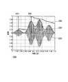
図1に、非線形平滑化の効果と、測定点がどのように計算されるかとを示す。信号110は、マイクロホン信号とすることができる。この信号110から、包絡線120が計算される。 FIG. 1 shows the effect of nonlinear smoothing and how the measurement points are calculated. The
図からわかるように、非線形平滑化から生じる信号130すなわち滑らかな包絡線130は、元の包絡線120と共に上昇し、ピーク(極大値)の後に時定数τに従って下降する。滑らかな包絡線130が上昇してピークに達して、元の包絡線120が滑らかな包絡線130の下になるよう滑らかな包絡線130が変化する各点が、定位キューの測定点となる。大きいピークにすぐに続く相対的に小さいピークでは、滑らかな包絡線130に上昇するフェーズが現れない(図の横軸の0.17秒の箇所で比較されたい)ので、測定点を生成しないことに留意されたい。
As can be seen, the
したがって、平滑化された包絡線は、必ず、元の包絡線と同様にすばやく上昇するが、よりゆっくりと下降する。どれほど速く下降するかは、時定数τによって決定される。その結果、元の包絡線のオンセットは、保存されるが、オンセットの後の信号部分について、平滑化がおこなわれる。この例では、平滑化は、一次無限インパルス応答(IIR)フィルタを介して実行されるが、他のタイプの平滑化フィルタを適用することもできる。Thus, the smoothed envelope always rises as quickly as theoriginal envelope, but descends more slowly. How fast it descends is determined by the time constant τ. As a result, theonset of theoriginal envelope is preserved, but the signal portion after theonset is smoothed. In this example, the smoothing is performed via a first order infinite impulse response (IIR) filter, but other types of smoothing filters can be applied.
次に、定位キューの測定点kMは、滑らかな包絡線が上昇相から下降相に変化し、したがって入力包絡線が滑らかな包絡線の下になる点によって定義される。Next, the measurement point kM of the localization cue is defined by the point at which the smooth envelope changes from the rising phase to the falling phase, so that the input envelope falls below the smooth envelope.
kM=∀k : xs(k−1)>x(k)∧xs(k−1)≦x(k−1)
これらの点140、150、および160は、必ず、入力包絡線の極大の直後に現れる。しかし、入力包絡線のすべての最大値が、測定点をもたらすわけではない。滑らかな包絡線信号を超える最大値だけが、測定点になる。その結果、より大きい最大値に続くより小さい最大値は、測定点を生成しない。それを行うことによって、このアルゴリズムは、続く最大値が、前の最大値より小さく、まもなく続く場合に、その続く最大値が、残響によって大きく影響されることを考慮に入れる。これは、最大値の発生の後の抑制期間になる。前に述べた、従来技術を表すアルゴリズムとは対照的に、この抑制相は、固定されているのではなく、信号依存である。特に、大きい最大値がより小さい最大値のすぐ後に続く場合に、このより大きい最大値も、測定点を生成する。kM = ∀k: xs (k−1)> x (k) ∧xs (k−1) ≦ x (k−1)
These
この平滑化は、アレイのすべてのマイクロホン信号について実行され、マイクロホン信号ごとに1つの測定点をもたらさなければならない。どの測定点を最終的な測定に使用するかは、測定点の時間的な順序付けと、マイクロホンの構成とによって決定される。 This smoothing must be performed for all microphone signals in the array, resulting in one measurement point for each microphone signal. Which measurement point is used for the final measurement is determined by the temporal ordering of the measurement points and the microphone configuration.
必ず、異なる信号の最初の測定点が使用され、ここで、最初とは、マイクロホン構成によって決定される最大TDOAによって与えられる値だけ、最大値で他の測定点に続いていることを意味する。 The first measurement point of the different signal is always used, where first means that it continues to the other measurement point at the maximum value by the value given by the maximum TDOA determined by the microphone configuration.
測定点が生成される時に、滑らかな包絡線に、初期包絡線に抑制係数θを乗じた値をセットすることができる。
抑制係数θは、前の最大値よりわずかに大きいだけの最大値を抑制するために導入することができる。これは、前の最大値よりわずかに大きいだけであるこれらの最大値が、残響によって強く影響されてもいる場合があることの発見を反映したものである。 The suppression coefficient θ can be introduced to suppress a maximum value that is only slightly larger than the previous maximum value. This reflects the discovery that these maxima, which are only slightly larger than the previous maxima, may also be strongly influenced by reverberation.
時定数τおよび抑制項θは、部屋の影響を反映する。定数τおよびθは、部屋特性(たとえば、残響時間)の推定値に基づいて適合させることができる。 The time constant τ and the suppression term θ reflect the influence of the room. The constants τ and θ can be adapted based on an estimate of room characteristics (eg, reverberation time).
図2に、追加の抑制項θの効果を示す。 FIG. 2 shows the effect of the additional suppression term θ.
図からわかるように、滑らかな包絡線信号230は、測定点240および250で元の包絡線信号220の上に上昇、その後、この持ち上げられた値からゆっくりと下降する。その結果、0.09秒の最大値に続く0.13秒の最大値は、振幅においてより大きいが、測定点を作らず、したがって抑止される。対照的に、0.09秒の最大値は、0.03秒にある前の最大値がかなりより小さいので、測定点250を生成する。 As can be seen, the
このアルゴリズムの性能は、包絡線信号の平滑化が対数領域で実行される場合に、さらに改善することができる。したがって、まず、信号包絡線の対数を計算することが有益である。包絡線の負の値を避けるために、最小の期待される信号レベルの対数を、結果の信号から引くことができる。 The performance of this algorithm can be further improved when the smoothing of the envelope signal is performed in the log domain. Therefore, it is beneficial to first calculate the logarithm of the signal envelope. In order to avoid negative envelope values, the logarithm of the minimum expected signal level can be subtracted from the resulting signal.
測定点から生じる測定のロバスト性を高めるために、点ではなく測定ウィンドウを使用することができる。測定ウィンドウの位置は、測定点の位置に基づくものとすることができる。これは、測定点を含む必要はないが、信号内の基準点として測定点を使用する。この測定ウィンドウは、固定サイズとする、または滑らかな包絡線信号に基づいて(たとえば、最後の最小値から現在の測定点まで)サイズを決定する、いずれかとすることができる。 In order to increase the robustness of the measurement resulting from the measurement point, a measurement window rather than a point can be used. The position of the measurement window can be based on the position of the measurement point. This need not include the measurement point, but uses the measurement point as a reference point in the signal. This measurement window can either be a fixed size or determine the size based on a smooth envelope signal (eg, from the last minimum to the current measurement point).
110 信号
120 包絡線
130 平滑化
140、150、160 測定点110
Claims (13)
Translated fromJapanese前記包絡線(120)の、オンセットを保存する非線形な平滑化を実行するステップと、
前記平滑化された包絡線(130)がその上昇からその下降に変化する点を測定点(140、150、160)として使用して、音源定位のキューを評価するステップと、を含み、
前記平滑化が、
Performingnon-linear smoothing of the envelope (120) to preserveonsets ;
Including using a point at which thesmoothed envelope (130) is changedto the Fall ontemperature or found that the as measuring point (140, 150, 160) and evaluating the queue of sound source localization, theSee
The smoothing is
到達の時間遅れ(TDOA)と、
両耳間強度差(IID)と、
両耳間包絡線の差(IED)と
のうちの1つまたは複数を含む、請求項1から5のいずれか一項に記載の方法。The cue for sound source localization
Time delay of arrival (TDOA),
Interaural strength difference (IID),
6. The method of any one of claims 1 to5 , comprising one or more of interaural envelope differences (IED).
Applications Claiming Priority (1)
| Application Number | Priority Date | Filing Date | Title |
|---|---|---|---|
| EP06000319AEP1806593B1 (en) | 2006-01-09 | 2006-01-09 | Determination of the adequate measurement window for sound source localization in echoic environments |
Publications (3)
| Publication Number | Publication Date |
|---|---|
| JP2007183637A JP2007183637A (en) | 2007-07-19 |
| JP2007183637A5 JP2007183637A5 (en) | 2011-01-06 |
| JP4662912B2true JP4662912B2 (en) | 2011-03-30 |
Family
ID=36096338
Family Applications (1)
| Application Number | Title | Priority Date | Filing Date |
|---|---|---|---|
| JP2006352183AExpired - Fee RelatedJP4662912B2 (en) | 2006-01-09 | 2006-12-27 | Determining the appropriate measurement window for sound source localization in a reverberant environment |
Country Status (4)
| Country | Link |
|---|---|
| US (1) | US8150062B2 (en) |
| EP (1) | EP1806593B1 (en) |
| JP (1) | JP4662912B2 (en) |
| DE (1) | DE602006001051T2 (en) |
Families Citing this family (5)
| Publication number | Priority date | Publication date | Assignee | Title |
|---|---|---|---|---|
| CN103796150B (en)* | 2012-10-30 | 2017-02-15 | 华为技术有限公司 | Processing method, device and system of audio signals |
| IL307592A (en) | 2017-10-17 | 2023-12-01 | Magic Leap Inc | Spatial audio for mixed reality |
| IL305799B2 (en) | 2018-02-15 | 2024-10-01 | Magic Leap Inc | Virtual reverberation in mixed reality |
| JP7478100B2 (en) | 2018-06-14 | 2024-05-02 | マジック リープ, インコーポレイテッド | Reverberation Gain Normalization |
| CN114586382B (en) | 2019-10-25 | 2025-09-23 | 奇跃公司 | A method, system and medium for determining and processing audio information |
Family Cites Families (22)
| Publication number | Priority date | Publication date | Assignee | Title |
|---|---|---|---|---|
| US4207623A (en)* | 1955-02-08 | 1980-06-10 | The United States Of America As Represented By The Secretary Of The Navy | Acoustic mine mechanism |
| US3838593A (en)* | 1972-11-06 | 1974-10-01 | Exxon Research Engineering Co | Acoustic leak location and detection system |
| US4581758A (en)* | 1983-11-04 | 1986-04-08 | At&T Bell Laboratories | Acoustic direction identification system |
| US4628529A (en)* | 1985-07-01 | 1986-12-09 | Motorola, Inc. | Noise suppression system |
| SE456279B (en)* | 1986-09-16 | 1988-09-19 | Bost & Co Ab | SET AND DEVICE FOR TIMING AN Acoustic Pulse |
| US5325436A (en)* | 1993-06-30 | 1994-06-28 | House Ear Institute | Method of signal processing for maintaining directional hearing with hearing aids |
| US5729612A (en)* | 1994-08-05 | 1998-03-17 | Aureal Semiconductor Inc. | Method and apparatus for measuring head-related transfer functions |
| US6990205B1 (en)* | 1998-05-20 | 2006-01-24 | Agere Systems, Inc. | Apparatus and method for producing virtual acoustic sound |
| US6826284B1 (en)* | 2000-02-04 | 2004-11-30 | Agere Systems Inc. | Method and apparatus for passive acoustic source localization for video camera steering applications |
| US7076433B2 (en)* | 2001-01-24 | 2006-07-11 | Honda Giken Kogyo Kabushiki Kaisha | Apparatus and program for separating a desired sound from a mixed input sound |
| US20030035553A1 (en)* | 2001-08-10 | 2003-02-20 | Frank Baumgarte | Backwards-compatible perceptual coding of spatial cues |
| GB0120450D0 (en)* | 2001-08-22 | 2001-10-17 | Mitel Knowledge Corp | Robust talker localization in reverberant environment |
| JP2003270034A (en)* | 2002-03-15 | 2003-09-25 | Nippon Telegr & Teleph Corp <Ntt> | Sound information analysis method, apparatus, program, and recording medium |
| BR0304540A (en)* | 2002-04-22 | 2004-07-20 | Koninkl Philips Electronics Nv | Methods for encoding an audio signal, and for decoding an encoded audio signal, encoder for encoding an audio signal, apparatus for providing an audio signal, encoded audio signal, storage medium, and decoder for decoding an audio signal. encoded audio |
| US7333622B2 (en)* | 2002-10-18 | 2008-02-19 | The Regents Of The University Of California | Dynamic binaural sound capture and reproduction |
| FI118247B (en)* | 2003-02-26 | 2007-08-31 | Fraunhofer Ges Forschung | Method for creating a natural or modified space impression in multi-channel listening |
| EP1586421B1 (en) | 2004-04-16 | 2008-03-05 | Honda Research Institute Europe GmbH | Self-calibrating orienting system for a manipulating device |
| EP1600791B1 (en) | 2004-05-26 | 2009-04-01 | Honda Research Institute Europe GmbH | Sound source localization based on binaural signals |
| JP2006060720A (en)* | 2004-08-24 | 2006-03-02 | Hitachi Ltd | Sound collection system |
| JP4529611B2 (en)* | 2004-09-17 | 2010-08-25 | 日産自動車株式会社 | Voice input device |
| ATE491503T1 (en)* | 2005-05-05 | 2011-01-15 | Sony Computer Entertainment Inc | VIDEO GAME CONTROL USING JOYSTICK |
| EP1736964A1 (en)* | 2005-06-24 | 2006-12-27 | Nederlandse Organisatie voor toegepast-natuurwetenschappelijk Onderzoek TNO | System and method for extracting acoustic signals from signals emitted by a plurality of sources |
- 2006
- 2006-01-09DEDE602006001051Tpatent/DE602006001051T2/enactiveActive
- 2006-01-09EPEP06000319Apatent/EP1806593B1/ennot_activeNot-in-force
- 2006-12-27JPJP2006352183Apatent/JP4662912B2/ennot_activeExpired - Fee Related
- 2007
- 2007-01-04USUS11/619,832patent/US8150062B2/ennot_activeExpired - Fee Related
Also Published As
| Publication number | Publication date |
|---|---|
| DE602006001051D1 (en) | 2008-06-12 |
| US8150062B2 (en) | 2012-04-03 |
| JP2007183637A (en) | 2007-07-19 |
| US20070160241A1 (en) | 2007-07-12 |
| DE602006001051T2 (en) | 2009-07-02 |
| EP1806593B1 (en) | 2008-04-30 |
| EP1806593A1 (en) | 2007-07-11 |
Similar Documents
| Publication | Publication Date | Title |
|---|---|---|
| JP6431884B2 (en) | Single channel speech dereverberation method and apparatus | |
| CA2827326C (en) | Apparatus and method for determining a measure for a perceived level of reverberation, audio processor and method for processing a signal | |
| JP5817366B2 (en) | Audio signal processing apparatus, method and program | |
| Gaubitch et al. | Performance comparison of algorithms for blind reverberation time estimation from speech | |
| JP6019969B2 (en) | Sound processor | |
| KR102651085B1 (en) | Dry sound and ambient sound separation | |
| JP5645419B2 (en) | Reverberation removal device | |
| JP2002508891A (en) | Apparatus and method for reducing noise, especially in hearing aids | |
| JP4662912B2 (en) | Determining the appropriate measurement window for sound source localization in a reverberant environment | |
| RU2751760C2 (en) | Audio capture using directional diagram generation | |
| CN110636408B (en) | Method for suppressing acoustic reverberation in an audio signal | |
| JP5627440B2 (en) | Acoustic apparatus, control method therefor, and program | |
| JP5915281B2 (en) | Sound processor | |
| Tachioka et al. | Dereverberation method with reverberation time estimation using floored ratio of spectral subtraction | |
| US12212928B2 (en) | Method for eliminating acoustic reverberation in an audio signal, and hearing instrument | |
| KR101073632B1 (en) | A zero-crossing-based multiple source localization apparatus in reverberant environments | |
| JP4950971B2 (en) | Reverberation removal apparatus, dereverberation method, dereverberation program, recording medium | |
| JP6102053B2 (en) | Sound processing apparatus and sound processing method | |
| CN120676303A (en) | Hearing aid, hearing measuring method and device thereof, and storage medium | |
| Eaton et al. | Estimation of the perceived level of reverberation using non-intrusive single-channel variance of decay rates | |
| HK1193525B (en) | Audio processor for generating a reverberated signal from a direct signal and method therefor |
Legal Events
| Date | Code | Title | Description |
|---|---|---|---|
| A621 | Written request for application examination | Free format text:JAPANESE INTERMEDIATE CODE: A621 Effective date:20071031 | |
| A131 | Notification of reasons for refusal | Free format text:JAPANESE INTERMEDIATE CODE: A131 Effective date:20100713 | |
| A601 | Written request for extension of time | Free format text:JAPANESE INTERMEDIATE CODE: A601 Effective date:20101012 | |
| A602 | Written permission of extension of time | Free format text:JAPANESE INTERMEDIATE CODE: A602 Effective date:20101018 | |
| A521 | Request for written amendment filed | Free format text:JAPANESE INTERMEDIATE CODE: A523 Effective date:20101110 | |
| A524 | Written submission of copy of amendment under article 19 pct | Free format text:JAPANESE INTERMEDIATE CODE: A524 Effective date:20101110 | |
| TRDD | Decision of grant or rejection written | ||
| A01 | Written decision to grant a patent or to grant a registration (utility model) | Free format text:JAPANESE INTERMEDIATE CODE: A01 Effective date:20101207 | |
| A01 | Written decision to grant a patent or to grant a registration (utility model) | Free format text:JAPANESE INTERMEDIATE CODE: A01 | |
| A61 | First payment of annual fees (during grant procedure) | Free format text:JAPANESE INTERMEDIATE CODE: A61 Effective date:20110104 | |
| R150 | Certificate of patent or registration of utility model | Free format text:JAPANESE INTERMEDIATE CODE: R150 | |
| FPAY | Renewal fee payment (event date is renewal date of database) | Free format text:PAYMENT UNTIL: 20140114 Year of fee payment:3 | |
| R250 | Receipt of annual fees | Free format text:JAPANESE INTERMEDIATE CODE: R250 | |
| R250 | Receipt of annual fees | Free format text:JAPANESE INTERMEDIATE CODE: R250 | |
| R250 | Receipt of annual fees | Free format text:JAPANESE INTERMEDIATE CODE: R250 | |
| LAPS | Cancellation because of no payment of annual fees |