JP4661465B2 - Control device - Google Patents
Control deviceDownload PDFInfo
- Publication number
- JP4661465B2 JP4661465B2JP2005258159AJP2005258159AJP4661465B2JP 4661465 B2JP4661465 B2JP 4661465B2JP 2005258159 AJP2005258159 AJP 2005258159AJP 2005258159 AJP2005258159 AJP 2005258159AJP 4661465 B2JP4661465 B2JP 4661465B2
- Authority
- JP
- Japan
- Prior art keywords
- rule
- image processing
- module
- control unit
- control device
- Prior art date
- Legal status (The legal status is an assumption and is not a legal conclusion. Google has not performed a legal analysis and makes no representation as to the accuracy of the status listed.)
- Expired - Fee Related
Links
Images


Landscapes
- Control Or Security For Electrophotography (AREA)
- Facsimiles In General (AREA)
Description
Translated fromJapanese本発明は、画像処理装置に関する。 The present invention relates to an image processing apparatus.
複合機は、コピーサービスモード、ファクシミリサービスモード、プリントサービスモード、及びスキャンサービスモードの4つのモードで夫々画像処理サービスを提供できるようになっている。そして、複合機を利用するユーザは、入出力原稿のサイズやカラー種別などに関する各種機能設定を自らの利用用途に応じて最適化した上で画像処理サービスの提供を受けるのが一般的である。
この種の複合機は多岐に渡る細かな機能設定ができるようになっているため、出力形式をOHP(Over Head Projector)シートとした上で印字態様を両面印刷にするといったような相両立しない機能設定が行われてしまう、いわゆるコンフリクトの問題が発生し得る。特許文献1や2には、このようなコンフリクトとなる設定の入力を阻止する仕組みを有する画像形成装置の開示がある。
This type of multifunction device can be set in a wide range of detailed functions. Therefore, it is an incompatible function such that the output format is an OHP (Over Head Projector) sheet and the printing mode is double-sided printing. There may be a so-called conflict problem in which settings are made. Patent Documents 1 and 2 disclose an image forming apparatus having a mechanism for preventing such conflicting setting input.
ところで、コンフリクトとなる設定の入力を阻止する仕組みの多くでは、各種画像処理サービスの提供に関与するハードウェアリソース及びソフトウェアリソースを特定し、特定した各リソースの機能の限界を画像処理サービスの種類毎に取り纏めることによって、コンフリクトとなる設定の組み合わせを表すコンフリクトルールを構築していた。
しかしながら、この手法によると、複合機に実装されるハードウェアリソースやソフトウェアリソースの一部がバージョンアップなどによって後から別のものに改変された場合、コンフリクトルールを一から構築し直さなければならないという不都合があった。
本発明は、このような背景の下に案出されたものであり、複合機のコンフリクトルールをそのハードウェアリソースやソフトウェアリソースの改変に応じて機動的に提示できるような仕組みを提供することを目的とする。By the way, in many of the mechanisms that prevent the input of conflicting settings, hardware resources and software resources that are involved in providing various image processing services are identified, and the function limit of each identified resource is determined for each type of image processing service. In this way, a conflict rule that represents a combination of settings that cause a conflict has been constructed.
However, according to this method, if some of the hardware resources and software resources implemented in the MFP are later changed to another one due to version upgrade etc., the conflict rule must be rebuilt from scratch. There was an inconvenience.
The present invention has been devised under such a background, and provides a mechanism that can flexibly present a conflict rule of a multi-function peripheral in accordance with modification of its hardware resource or software resource. Objective.
本発明の好適な態様である制御装置は、画像処理に関する複数のデバイスを備え、複数の画像処理サービスモードのいずれかで動作する画像処理装置のユーザインターフェースを制御する制御装置であって、前記ユーザインターフェースを介してユーザが行う各種機能設定に従って当該ユーザの指示に係る画像処理ジョブの各処理を実行するための各ソフトウェアモジュールであって、各々が前記複数のデバイスのいずれかに対応する第1のソフトウェアモジュールと、前記第1のソフトウェアモジュールとともに実行される第2のソフトウェアモジュールとをそれぞれ複数記憶したソフトウェア記憶手段と、前記ソフトウェア記憶手段の各ソフトウェアモジュールを夫々起動する各手段であって、ユーザの指示に係る画像処理ジョブの各処理を各々が起動させたソフトウェアモジュールを用いて実行する複数のモジュール制御手段と、前記各モジュール制御手段を識別する識別子と、それらのモジュール制御手段の処理能力に依存した機能設定のルールを表すルール定義情報とを各々対応付けて記憶したルール記憶手段と、前記複数の画像処理サービスモードのうちの前記ユーザの指示に係るモードで指示され得る画像処理ジョブの処理に関与する前記デバイスに対応する前記第1のソフトウェアモジュールを特定し、特定したソフトウェアモジュールを用いて実行される前記モジュール制御手段を特定する第1の特定手段と、前記ユーザの指示に係るモードで指示され得る画像処理ジョブの処理に関与する前記第2のソフトウェアモジュールであって、前記第1の特定手段により特定された第1のソフトウェアモジュールとともに実行される第2のソフトウェアモジュールを用いて実行される前記モジュール制御手段を特定する第2の特定手段と、前記第1の特定手段及び前記第2の特定手段により特定されたモジュール制御手段の識別子と対応付けて前記ルール記憶手段に記憶された各ルール定義情報を順次参照し、参照した各ルール定義情報が表すルールの全部を充足するルールであるコンフリクトルールを前記ユーザインターフェースを介して提示するルール提示手段とを備えることを特徴とする。Acontrol apparatus according to a preferred aspect of the present invention is acontrol apparatusthat includes a plurality of devices related to image processing and controls a user interface of an image processing apparatus that operates in one of a plurality of image processing service modes. Each software module for executing each process of an image processing job according to an instruction of the user according to various function settings performed by the user via an interface, each of the software modulescorresponding to one of the plurality of devices Software storage means for storing a plurality of software modules and a plurality of second software modules executed together with the first software module, and means for starting each software module of the software storage means, Each process of the image processing job related to the instruction A rule definition representing a plurality of module control means that execute each using a software module that is activated, an identifier for identifying each module control means, and a function setting rule depending on the processing capability of the module control means Rule storage means for storing information in association with each other, and the device corresponding to the device involved in processing of an image processing job that can be instructed in a mode according to an instruction from the user among the plurality of image processing service modes. A first software module that identifies one software module, identifies the module control module that is executed using the identified software module, and is involved in processing an image processing job that can be commanded in a mode according to the user's command The second software module, wherein the first specifying means Second specifying means for specifying the module control means to be executed using the second software module executed together with the specified first software module, the first specifying means and the second specifying means The rule definition information stored in the rule storage unit in association with the identifier of the module control unit identified by the above is sequentially referred to, and a conflict rule that is a rule satisfying all the rules represented by the referenced rule definition information is obtained. And a rule presenting means for presenting via the user interface .
この態様において、前記ユーザインターフェースは、前記ユーザによる前記モードの切り換えの指示を受け付け、前記第1の特定手段及び前記第2の特定手段は、当該切り換え後のモードに応じた前記モジュール制御手段を夫々特定するようにしてもよい。In this aspect, the user interface accepts an instruction to switch the mode by the user, and the first specifying means and the second specifying means respectively specify the module control means corresponding to the mode after the switching. It may be specified.
この態様において、前記各ソフトウェアモジュールを起動する複数のモジュール制御手段は、複数の層に階層化された上で実装され、前記ルール提示手段は、より低い層に実装されたモジュール制御手段の識別子と対応付けられたルール定義情報から順次参照するようにしてもよい。 In this aspect, the plurality of module control means for starting each of the software modules is implemented after being hierarchized into a plurality of layers, and the rule presenting means includes an identifier of the module control means implemented in a lower layer. You may make it refer sequentially from the associated rule definition information.
また、前記複数のモジュール制御手段には、スキャン又は印字を行うハードウェアを駆動させるハードウェア制御手段、画像処理ジョブが該当する画像処理サービスモードに応じて前記ハードウェアの駆動手順を調停するサービス機能制御手段、ユーザの指示に係る画像処理ジョブを生成するアプリケーション制御手段、及び前記サービス機能制御手段にオプション機能を与えるプラグイン制御手段のうち2つ以上が含まれるようにしてもよい。 The plurality of module control means includes a hardware control means for driving hardware for scanning or printing, and a service function for arbitrating the hardware driving procedure according to an image processing service mode to which an image processing job corresponds. Two or more of a control unit, an application control unit that generates an image processing job according to a user instruction, and a plug-in control unit that provides an optional function to the service function control unit may be included.
前記ハードウェア制御手段の識別子と対応付けて前記ルール記憶手段に記憶されたルール定義情報は、特定のハードウェアに依存したルールを表すようにしてもよい。 The rule definition information stored in the rule storage unit in association with the identifier of the hardware control unit may represent a rule depending on specific hardware.
また、前記サービス機能制御手段の識別子と対応付けて前記ルール記憶手段に記憶されたルール定義情報は、複数のハードウェアに共通するルールを表すようにしてもよい。 The rule definition information stored in the rule storage unit in association with the identifier of the service function control unit may represent a rule common to a plurality of hardware.
前記アプリケーション機能制御手段の識別子と対応付けて前記ルール記憶手段に記憶されたルール定義情報は、画像処理サービスモードの特定の種別に依存したルールを表すようにしてもよい。 The rule definition information stored in the rule storage unit in association with the identifier of the application function control unit may represent a rule depending on a specific type of image processing service mode.
前記プラグイン制御手段の識別子と対応付けて前記ルール記憶手段に記憶されたルール定義情報は、前記画像処理サービスモードの特定の種別に依存したルールよりも更に限定されたルールを表すようにしてもよい。 The rule definition information stored in the rule storage unit in association with the identifier of the plug-in control unit may represent a more limited rule than a rule depending on a specific type of the image processing service mode. Good.
また、自装置に実装されたあるハードウェアが新たなハードウェアに置き換えられたとき、そのハードウェアを駆動させるハードウェア制御手段の識別子と対応付けて前記ルール記憶手段に記憶されたルール定義情報を新たな内容のルール定義情報に更新する更新手段を更に備えてもよい。 In addition, when a piece of hardware installed in the own device is replaced with new hardware, the rule definition information stored in the rule storage unit is associated with the identifier of the hardware control unit that drives the hardware. Update means for updating the rule definition information with new contents may be further provided.
本発明によると、複合機のコンフリクトルールをそのハードウェアリソースやソフトウェアリソースの改変に応じて機動的に提示できるような仕組みを提供することができる。 According to the present invention, it is possible to provide a mechanism capable of flexibly presenting a conflict rule of a multi-function peripheral in accordance with modification of its hardware resource or software resource.
(発明の実施の形態)
本実施形態の特徴は、複合機のユーザインターフェースを介した各種機能設定の条件を表すルール(以下、単に「ルール」と呼ぶ)を、その複合機に実装されたソフトウェアリソースのモジュール毎に個別に保持するようにした点である。
本実施形態に係る複合機は、以下の4つのサービスモードで各種画像処理サービスを提供する。
(1)スキャンサービスモード
このモードでは、紙媒体からスキャンした画像を画像データ化して記録媒体に格納するサービスであるスキャンサービスを提供する。
(2)コピーサービスモード
このモードでは、紙媒体からスキャンした画像を別の一又は複数の紙媒体にプリントして複写物を生成するサービスであるコピーサービスを提供する。
(3)FAXサービスモード
このモードでは、自機のアドレス宛てに電話回線経由で伝送されてくる画像を紙媒体にプリントして出力し、また、紙媒体からスキャンした画像を外部のアドレス宛てに電話回線経由で伝送するサービスであるFAXサービスを提供する。
(4)プリントサービスモード
このモードでは、自機のアドレス宛てにネットワーク経由で伝送されてくる画像を紙媒体にプリントして出力するサービスであるプリントサービスを提供する。(Embodiment of the Invention)
A feature of the present embodiment is that rules (hereinafter simply referred to as “rules”) representing various function setting conditions via the user interface of the multifunction device are individually set for each module of software resources installed in the multifunction device. This is the point that I kept.
The multifunction peripheral according to the present embodiment provides various image processing services in the following four service modes.
(1) Scan Service Mode In this mode, a scan service, which is a service for converting an image scanned from a paper medium into image data and storing it in a recording medium, is provided.
(2) Copy Service Mode In this mode, a copy service, which is a service for generating a copy by printing an image scanned from a paper medium on one or more other paper media, is provided.
(3) FAX service mode In this mode, an image transmitted via the telephone line to the address of the machine is printed and output on a paper medium, and an image scanned from the paper medium is called to an external address. A FAX service, which is a service that is transmitted via a line, is provided.
(4) Print service mode In this mode, a print service is provided, which is a service for printing an image transmitted to the address of its own device via a network on a paper medium and outputting it.
図1は、複合機のハードウェア概略構成図である。図に示すように、複合機は、スキャンデバイス11、プリントデバイス12、通信デバイス13、ユーザインターフェース(以下、「UI」と呼ぶ)デバイス14、CPU15、揮発性メモリ16、及び不揮発性メモリ17の各ハードウェアリソースを備える。
スキャンデバイス11は、CCD(Charge Coupled Device)や光源などといった、画像スキャン制御を実現すべく搭載されたデバイス群の総称である。
プリントデバイス12は、感光体ドラムや帯電器などといった、画像プリント制御を実現すべく搭載されたデバイス群の総称である。
通信デバイス13は、モデムや各種インターフェースユニットなどといった、外部ノードとの通信制御を実現すべく搭載されたデバイス群の総称である。
UIデバイス14は、タッチパネルやタッチスクリーンディスプレイなどといった、UI制御を実現すべく搭載されたデバイス群の総称である。
揮発性メモリ16は、CPU15のワークエリアとして各種プログラムやデータを記憶する。FIG. 1 is a schematic hardware configuration diagram of a multifunction machine. As shown in the figure, the multifunction peripheral includes a
The
The
The
The
The
不揮発性メモリ17は、UI制御プログラム17a、プラグインアプリケーションプログラム17b、基本アプリケーションプログラム17c、スキャン機能制御プログラム17d、コピー機能制御プログラム17e、FAX機能制御プログラム17f、プリント機能制御プログラム17g、スキャンデバイス制御プログラム17h、通信デバイス制御プログラム17i、プリントデバイス制御プログラム17jが記憶される。なお、これら各プログラムのうちプラグインアプリケーションプログラム17bは、不揮発性メモリ17に予め記憶されているわけではなく、ユーザのカスタマイズ操作に従って図示しないサーバ装置からダウンロードされる。 The
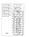
図2は、複合機のソフトウェア概略構成図である。図に示す各ソフトウェアモジュールは、CPU15が揮発性メモリ16をワークエリアとして不揮発性メモリ17の各種プログラムを起動させることにより実現される。具体的には、UI制御部51、プラグイン制御部52、アプリケーション制御部53、スキャン機能制御部54、コピー機能制御部55、FAX機能制御部56、プリント機能制御部57、スキャン制御部58、通信制御部59、プリント制御部60の10のソフトウェアモジュールが実現される。これらの各制御部は、最もハードウェアに近い、スキャン制御部58、通信制御部59、プリント制御部60の層(以下、この層を「第1層」と呼ぶ)、スキャン機能制御部54、コピー機能制御部55、FAX機能制御部56、及びプリント機能制御部57の層(以下、この層を「第2層」と呼ぶ)、アプリケーション制御部53の層(以下、この層を「第3層」と呼ぶ)、プラグイン制御部52の層(以下、この層を「第4層」と呼ぶ)、UI制御部51の層(以下、この層を「第5層」と呼ぶ)に階層化された上で実装される。 FIG. 2 is a schematic software configuration diagram of the multifunction machine. Each software module shown in the figure is realized by the
UI制御部51は、UI制御プログラム17aを起動することによって実現するソフトウェアモジュールであり、各種サービスに応じたインターフェース画面をUIインターフェースに表示させ、同画面を介して入力される各種指令を下位の層のソフトウェアモジュールへ伝達する。 The
プラグイン制御部52は、プラグインアプリケーションプログラム17bを起動することによって実現するソフトウェアモジュールであり、例えば、スキャンされた画像に文字認識処理(OCR処理)を施してテキストデータ化するなどといったような、各種画像処理サービスのオプション機能を各機能制御部に付与する。 The plug-in
アプリケーション制御部53は、基本アプリケーションプログラム17cを起動することによって実現するソフトウェアモジュールであり、UI制御部51から伝達される指令に係る各種サービスの画像処理ジョブを生成する。そして、スキャンサービスモードで生成された画像処理ジョブをスキャン機能制御部54へ、コピーサービスモードで生成された画像処理ジョブをコピー機能制御部55へ、FAXサービスモードで生成された画像処理ジョブをFAX機能制御部56へ、プリントサービスモードで生成された画像処理ジョブをプリント機能制御部57へ夫々供給する。 The
スキャン機能制御部54、コピー機能制御部55、FAX機能制御部56、及びプリント機能制御部57は、スキャン機能制御プログラム17d、コピー機能制御プログラム17e、FAX機能制御プログラム17f、及びプリント機能制御プログラム17gを夫々起動させることによって実現するソフトウェアモジュールであり、自身に供給された画像処理ジョブを実現するためにデバイスに実行させる各処理を特定し、特定した処理の実行を指示する指令を、スキャン制御部58、通信制御部59、プリント制御部60へ供給する。例えば、コピーサービスにおけるコピージョブの供給を受けたコピー機能制御部55は、画像のスキャン処理を行う指令をスキャン制御部58へ供給した後、画像のプリント処理を行う指令をプリント制御部60へ供給する。 The scan
スキャン制御部58、通信制御部59、及びプリント制御部60は、スキャンデバイス制御プログラム17h、通信デバイス制御プログラム17i、プリントデバイス制御プログラム17jを夫々起動させることによって実現するソフトウェアモジュールであり、自身に供給された指令に従ってデバイスを駆動させる。 The
図1に戻り、不揮発性メモリ17には、ルール定義テーブル17kが記憶される。
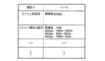
図3は、ルール定義テーブル17kのデータ構造図である。図に示すように、このテーブルは、CPU15によって実現される各ソフトウェアモジュールの各々と対応付けられた複数のレコードの集合体である。そして、このテーブルを構成する1つのレコードは、「識別子」と「ルール」の2つのフィールドを有している。「識別子」のフィールドには、各ソフトウェアモジュールを識別する識別子が記憶される。「ルール」のフィールドには、UIを介した各種機能設定のルールを示すルール定義情報が記憶される。このフィールドに記憶されるルールの内容は、各ソフトウェアモジュールの処理能力に応じて異なる。例えば、図3に示すテーブルの最上段のレコードには、「スキャン制御部」の識別子と対応付けて、「解像度:200dpi〜1200dpi」という内容のルール定義情報が記憶されている。これは、スキャン制御部58によって稼動されるスキャンデバイス11が、200dpi〜1200dpiの解像度の設定でなければ駆動できないようになっていることを表している。また、その下のレコードには、「スキャン機能制御部」の識別子と対応付けて、「解像度 倍率 200dpi 100%〜600% 400dpi 50%〜300% 600dpi 33%〜200%」という内容のルール定義情報が記憶されている。これは、スキャン機能制御部54が、「200dpi:100%〜600%」、「400dpi:50%〜300%」、又は「600dpi:33%〜200%」の機能設定の下に指示された画像処理ジョブでなければ処理できないことを示している。
他のレコードに記憶されたルール定義情報も同様であり、各ソフトウェアモジュールの処理能力に依存した内容のルール定義情報が「ルール」のフィールドに夫々記憶される。それらのルール定義情報は、各ソフトウェアモジュールの処理能力を加味して決定されることが望ましい。例えば、スキャン制御部58、通信制御部59、プリント制御部60のルール定義情報であれば、各々が駆動するハードウェアの能力に依存して決定されることが望ましく、スキャン機能制御部54、コピー機能制御部55、FAX機能制御部56、プリント機能制御部57のルール定義情報であれば、下位の複数のモジュールを通じて駆動する複数のハードウェアに共通のものとして決定されることが望ましい。また、アプリケーション制御部53のルール定義情報であれば、各種画像処理サービスの内容を加味して決定されることが望ましい。更に、プラグイン制御部52のルール定義情報であれば、アプリケーション制御部53のものよりも更に限定されたルールとなることが望ましい。Returning to FIG. 1, the
FIG. 3 is a data structure diagram of the rule definition table 17k. As shown in the figure, this table is a collection of a plurality of records associated with each software module realized by the
The same applies to the rule definition information stored in other records, and the rule definition information whose contents depend on the processing capability of each software module is stored in the “rule” field. The rule definition information is preferably determined in consideration of the processing capability of each software module. For example, in the case of the rule definition information of the
図4は、本実施形態に係る複合機の特徴的な動作を示すフローチャートである。図に示す動作は、ユーザが、UIを介して何れかのサービスモードへの切り換えの指示を下したことをトリガーとして開始される。
サービスモードへの切り換えの指示が下されると、CPU15は、そのサービスモードの画像処理ジョブの処理に関与することになる第1層のソフトウェアモジュールを特定し、特定したソフトウェアモジュールの識別子と対応付けてルール定義テーブル17kに記憶されたルール定義情報を参照することによって第1層のルールを取得する(S100)。
このステップで特定されるソフトウェアモジュールは、切り替えられたサービスモードの種類に応じて異なる。例えば、スキャンサービスモードであればスキャン制御部58が関与し、コピーサービスモードあればスキャン制御部58とプリント制御部60の両制御部が関与することになる。また、FAXサービスモードであればスキャン制御部58と通信制御部59が関与し、プリントサービスモードであればプリント制御部60と通信制御部59が関与することになる。FIG. 4 is a flowchart showing a characteristic operation of the multifunction peripheral according to the present embodiment. The operation shown in the figure is triggered by the user giving an instruction to switch to any service mode via the UI.
When an instruction to switch to the service mode is issued, the
The software module specified in this step differs depending on the type of service mode that has been switched. For example, the
CPU15は、第2層のソフトウェアモジュールを特定し、特定したソフトウェアモジュールの識別子と対応付けてルール定義テーブル17kに記憶されたルール定義情報を参照することによって、第1層と第2層のソフトウェアモジュールに共通するルールを取得する(S110)。
このステップで特定されるソフトウェアモジュールも、切り替えられたサービスモードの種類に応じて異なり、スキャンサービスモードであればスキャン機能制御部54が、コピーサービスモードであればコピー機能制御部55が、FAXサービスモードであれがFAX機能制御部56が、プリントサービスモードであればプリント機能制御部57が夫々特定されることになる。The
The software module specified in this step also differs depending on the type of the switched service mode. The scan
CPU15は、第3層のソフトウェアモジュール、つまり、アプリケーション制御部53の識別子と対応付けてルール定義テーブル17kに記憶されたルール定義情報を参照することによって、第1層乃至第3層のソフトウェアモジュールに共通するルールを取得する(S120)。
更に、CPU15は、第4層のソフトウェアモジュール、つまり、プラグイン制御部52があるか否かを判断する(S130)。上述したように、プラグイン制御部52は、不揮発性メモリ17のプラグインアプリケーションを起動することによって実現され、プラグインアプリケーション自体は外部のサーバ装置からダウンロードすることによってはじめて実装されるようになっている。従って、そのようなプラグインアプリケーションのダウンロードが行われていればこのステップの判断結果は「YES」となってステップ140に進み、ダウンロードが行われていなければこのステップの判断結果は「NO」となってステップ150に進む。The
Further, the
ステップ140に進むと、CPU15は、プラグイン制御部52の識別子と対応付けてルール定義テーブル17kに記憶されたルール定義情報を参照することによって、第1層乃至第4層のソフトウェアモジュールに共通するルールを取得する。
ステップ150に進むと、CPU15は、ステップ100乃至ステップ130、又はステップ100乃至ステップ140を経て得られたルール定義情報のすべてを充足するルールを、コンフリクトルールとしてユーザインターフェースに表示させる。In step 140, the
In step 150, the
以上説明した一連の処理について、更に具体的に説明する。図5は、スキャンサービスモードへの切り換えが指示された場合における処理内容の詳細を示す図である。
図に示すステップ100では、スキャンサービスの画像処理ジョブの処理に関与する第1層のソフトウェアモジュールがスキャン制御部58であることから、そのスキャン制御部58と対応するルール定義情報が表す「解像度 200dpi〜1200dpi」というルール1が取得される。The series of processes described above will be described more specifically. FIG. 5 is a diagram showing details of processing contents when switching to the scan service mode is instructed.
In
ステップ110では、スキャンサービスの画像処理ジョブの処理に関与する第2層のソフトウェアモジュールがスキャン機能制御部54であることから、そのスキャン機能制御部54と対応するルール定義情報を基に「解像度:倍率 200dpi:100%〜600% 400dpi:50%〜300% 600dpi:33%〜200% 」のルール2が取得される。ここでは、スキャン機能制御部54が倍率変更の処理を司るため、その処理能力に依存した倍率制限に関するルールが新たに付加される。 In step 110, since the second layer software module involved in the processing of the image processing job of the scan service is the scan
ステップ120では、第3層のソフトウェアモジュールであるアプリケーション制御部53と対応するルール定義情報を基に「解像度:倍率 200dpi:100%〜600% 400dpi:50%〜300%」のルール3が取得される。ここでは、アプリケーション制御部53が600dpi:33%〜200%の設定での処理ができないことから、その設定を許容する部分のルールが除かれる。 In step 120, rule 3 of “resolution:
ステップ140では、第3層のソフトウェアモジュールであるプラグイン制御部52と対応するルール定義情報を基に「解像度:倍率 400dpi:50%〜300%」のルール4が取得される。ここでは、プラグイン制御部52が、200dpi:100%〜600%の設定での処理ができないことから、その設定を許容する部分のルールが除かれる。 In step 140, rule 4 of “resolution: magnification 400 dpi: 50% to 300%” is acquired based on the rule definition information corresponding to the plug-in
ステップ150では、ステップ100乃至ステップ140を経て最終的に絞り込まれたルールである「解像度:倍率 400dpi:50%〜300%」が、コンフリクトルールとしてユーザインターフェースに表示される。 In step 150, the rule “resolution: magnification 400 dpi: 50% to 300%” that is finally narrowed down through
以上説明した本実施形態によると、UIを介した各種機能設定のルールを複合機に実装される各ソフトウェアモジュール毎に定義してテーブル化しておく一方で、下位の層に実装されたソフトウェアモジュールと対応するルールから上位の層に実装されたソフトウェアモジュールと対応するルールを順次参照し、それらのすべてを充足するルールをコンフリクトルールとしてユーザインターフェースに提示するようになっている。従って、複合機が実装するコンフリクトルールの一部が別のものに変更されるたびにその部分のルールだけを新しいものと差換えていくことにより、適正なコンフリクトルールを常に提示していくことができる。 According to the present embodiment described above, various function setting rules via the UI are defined and tabulated for each software module implemented in the multifunction peripheral, while the software modules implemented in the lower layers From the corresponding rule, the software module installed in the upper layer and the corresponding rule are sequentially referred to, and a rule satisfying all of them is presented as a conflict rule on the user interface. Therefore, every time a part of the conflict rule implemented by the multi-function peripheral is changed to another one, it is possible to always present an appropriate conflict rule by replacing only that part of the rule with a new one.
(他の実施形態)
本願発明は、種々の変形実施が可能である。
上記実施形態では、UIを介して何れかのサービスモードへの切り換えの指示を下したことをトリガーとして図に示す一連の処理が開始され、切り換えの指示に係るコンフリクトルールがUIに提示されるようになっていた。これに対し、複合機自体が起動されたことをトリガーとして、各画像処理サービス毎に図4に示す処理を実行してそれらのサービスモード毎のコンフリクトルールを取得しておき、サービスモードが切り替わる毎に、対応するコンフリクトルールをUIに表示させるようにしてもよい。(Other embodiments)
The present invention can be modified in various ways.
In the above embodiment, a series of processing shown in the figure is started when an instruction to switch to any of the service modes is given via the UI, and a conflict rule related to the switching instruction is presented to the UI. It was. On the other hand, every time the service mode is switched by executing the processing shown in FIG. 4 for each image processing service and acquiring the conflict rule for each service mode, triggered by the activation of the MFP itself. In addition, the corresponding conflict rule may be displayed on the UI.
11…スキャンデバイス、12…プリントデバイス、13…通信デバイス、14…UIデバイス、15…CPU、16…揮発性メモリ、17…不揮発性メモリ、51…UI制御部、52…プラグイン制御部、53…アプリケーション制御部、54…スキャン機能制御部、55…コピー機能制御部、56…FAX機能制御部、57…プリント機能制御部、58…スキャン制御部、59…通信制御部、60…プリント制御部DESCRIPTION OF
Claims (9)
Translated fromJapanese前記ユーザインターフェースを介してユーザが行う各種機能設定に従って当該ユーザの指示に係る画像処理ジョブの各処理を実行するための各ソフトウェアモジュールであって、各々が前記複数のデバイスのいずれかに対応する第1のソフトウェアモジュールと、前記第1のソフトウェアモジュールとともに実行される第2のソフトウェアモジュールとを夫々複数記憶したソフトウェア記憶手段と、
前記ソフトウェア記憶手段の各ソフトウェアモジュールを夫々起動する各手段であって、ユーザの指示に係る画像処理ジョブの各処理を各々が起動させたソフトウェアモジュールを用いて実行する複数のモジュール制御手段と、
前記各モジュール制御手段を識別する識別子と、それらのモジュール制御手段の処理能力に依存した機能設定のルールを表すルール定義情報とを各々対応付けて記憶したルール記憶手段と、
前記複数の画像処理サービスモードのうちの前記ユーザの指示に係るモードで指示され得る画像処理ジョブの処理に関与する前記デバイスに対応する前記第1のソフトウェアモジュールを特定し、特定したソフトウェアモジュールを用いて実行される前記モジュール制御手段を特定する第1の特定手段と、
前記ユーザの指示に係るモードで指示され得る画像処理ジョブの処理に関与する前記第2のソフトウェアモジュールであって、前記第1の特定手段により特定された第1のソフトウェアモジュールとともに実行される第2のソフトウェアモジュールを用いて実行される前記モジュール制御手段を特定する第2の特定手段と、
前記第1の特定手段及び前記第2の特定手段により特定されたモジュール制御手段の識別子と対応付けて前記ルール記憶手段に記憶された各ルール定義情報を順次参照し、参照した各ルール定義情報が表すルールの全部を充足するルールであるコンフリクトルールを前記ユーザインターフェースを介して提示するルール提示手段と
を備えた制御装置。A control apparatus that includes a plurality of devices related to image processing and controls a user interface of an image processing apparatus that operates in one of a plurality of image processing service modes,
A respective software modules for performing the respective processes of the image processing job according to the instruction of the user according to various function setting performed by the user viathe userinterface, the each corresponding to one of said plurality of devices Software storage means for storing apluralityof software moduleseach including onesoftware module and a second software module executed together with the first software module ;
A plurality of module control means each for starting each software module of the software storage means, each module executing a processing of an image processing job according to a user's instruction using each software module;
A rule storage means for storing an identifier for identifying each of the module control means and rule definition information representing a rule for function setting depending on the processing capability of the module control means;
The first software module corresponding to the device involved in theprocessing of an image processing job that can be instructed in a modeaccording to an instruction from the user among the plurality of image processing service modes is identified, and the identifiedsoftware module is usedthe module control unitto be executed Te afirst specifying unit thatspecific,
The second software module involved in the processing of an image processing job that can be instructed in a mode according to the user instruction, the second software module being executed together with the first software module specified by the first specifying means Second specifying means for specifying the module control means to be executed using the software module;
Each rule definition information stored in the rule storage means is sequentially referred to in association with the identifier ofthe module control meansspecified by the first specification means and the second specification means, and each rule definition information referred to iscontroller having a rule presenting means for the conflict rules is a rule that satisfies all of the rules presented via the user interface that represents.
前記ユーザインターフェースは、前記ユーザによる前記画像処理サービスモードの切り換えの指示を受け付け、The user interface accepts an instruction to switch the image processing service mode by the user;
前記第1の特定手段及び前記第2の特定手段は、当該切り換え後の画像処理サービスモードに応じた前記モジュール制御手段を夫々特定するThe first specifying unit and the second specifying unit specify the module control unit corresponding to the image processing service mode after the switching, respectively.
ことを特徴とする制御装置。A control device characterized by that.
前記各ソフトウェアモジュールを起動する複数のモジュール制御手段は、
複数の層に階層化された上で実装され、
前記ルール提示手段は、
より低い層に実装されたモジュール制御手段の識別子と対応付けられたルール定義情報から順次参照する
ことを特徴とする制御装置。Thecontrol device according to claim1 ,
A plurality of module control means for starting each of the software modules,
Implemented in multiple layers,
The rule presenting means is:
Acontrol device characterized by sequentially referencing from rule definition information associated with an identifier of a module control means mounted in a lower layer.
前記複数のモジュール制御手段には、
スキャン又は印字を行うハードウェアを駆動させるハードウェア制御手段、画像処理ジョブが該当する画像処理サービスモードに応じて前記ハードウェアの駆動手順を調停するサービス機能制御手段、ユーザの指示に係る画像処理ジョブを生成するアプリケーション制御手段、及び前記サービス機能制御手段にオプション機能を与えるプラグイン制御手段のうち2つ以上が含まれる
ことを特徴とする制御装置。Thecontrol device according to any one of claims 1 to 3,
In the plurality of module control means,
Hardware control means for driving hardware for scanning or printing, service function control means for adjusting the hardware driving procedure according to an image processing service mode to which the image processing job corresponds, and an image processing job according to a user instructioncontrol apparatus characterized by includes two or more of the plug-in control means for providing the optional function to the application control unit, and the service function control means for generating a.
前記ハードウェア制御手段の識別子と対応付けて前記ルール記憶手段に記憶されたルール定義情報は、
特定のハードウェアに依存したルールを表す
ことを特徴とする制御装置。Thecontrol device according to claim 4,
The rule definition information stored in the rule storage unit in association with the identifier of the hardware control unit is:
Acontrol device characterized by representing rules that depend on specific hardware.
前記サービス機能制御手段の識別子と対応付けて前記ルール記憶手段に記憶されたルール定義情報は、
複数のハードウェアに共通するルールを表す
ことを特徴とする制御装置。Thecontrol device according to claim 4,
The rule definition information stored in the rule storage means in association with the identifier of the service function control means is:
Acontrol device characterized by expressing a rule common to a plurality of hardware.
前記アプリケーション機能制御手段の識別子と対応付けて前記ルール記憶手段に記憶されたルール定義情報は、
画像処理サービスモードの特定の種別に依存したルールを表す
ことを特徴とする制御装置。Thecontrol device according to claim 4,
The rule definition information stored in the rule storage means in association with the identifier of the application function control means is
Acontrol device representing a rule depending on a specific type of image processing service mode.
前記プラグイン制御手段の識別子と対応付けて前記ルール記憶手段に記憶されたルール定義情報は、
前記画像処理サービスモードの特定の種別に依存したルールよりも更に限定されたルールを表す
ことを特徴とする制御装置。Thecontrol device according to claim 4,
The rule definition information stored in the rule storage means in association with the identifier of the plug-in control means is
Thecontrol device represents a rule more limited than a rule depending on a specific type of the image processing service mode.
自装置に実装されたあるハードウェアが新たなハードウェアに置き換えられたとき、
そのハードウェアを駆動させるハードウェア制御手段の識別子と対応付けて前記ルール記憶手段に記憶されたルール定義情報を新たな内容のルール定義情報に更新する更新手段
を更に備えた制御装置。Thecontrol device according to any one of claims 4 to 8,
When a piece of hardware installed in your device is replaced with new hardware,
Acontrol device further comprising an updating means for updating the rule definition information stored in the rule storage means in association with the identifier of the hardware control means for driving the hardware to the new rule definition information.
Priority Applications (1)
| Application Number | Priority Date | Filing Date | Title |
|---|---|---|---|
| JP2005258159AJP4661465B2 (en) | 2005-09-06 | 2005-09-06 | Control device |
Applications Claiming Priority (1)
| Application Number | Priority Date | Filing Date | Title |
|---|---|---|---|
| JP2005258159AJP4661465B2 (en) | 2005-09-06 | 2005-09-06 | Control device |
Publications (2)
| Publication Number | Publication Date |
|---|---|
| JP2007074267A JP2007074267A (en) | 2007-03-22 |
| JP4661465B2true JP4661465B2 (en) | 2011-03-30 |
Family
ID=37935352
Family Applications (1)
| Application Number | Title | Priority Date | Filing Date |
|---|---|---|---|
| JP2005258159AExpired - Fee RelatedJP4661465B2 (en) | 2005-09-06 | 2005-09-06 | Control device |
Country Status (1)
| Country | Link |
|---|---|
| JP (1) | JP4661465B2 (en) |
Families Citing this family (3)
| Publication number | Priority date | Publication date | Assignee | Title |
|---|---|---|---|---|
| JP5089464B2 (en) | 2008-04-02 | 2012-12-05 | キヤノン株式会社 | Management device, management method, and program |
| JP6142591B2 (en)* | 2013-03-13 | 2017-06-07 | 株式会社リコー | Prohibition processing program, prohibition processing device, prohibition processing method, and printing system |
| JP7118714B2 (en)* | 2018-04-13 | 2022-08-16 | キヤノン株式会社 | IMAGE FORMING APPARATUS AND CONTROL METHOD AND CONTROL PROGRAM FOR THE IMAGE FORMING APPARATUS |
Family Cites Families (10)
| Publication number | Priority date | Publication date | Assignee | Title |
|---|---|---|---|---|
| JPH10105623A (en)* | 1996-09-27 | 1998-04-24 | Hitachi Ltd | Hierarchical workflow management method and workflow document circulation method |
| JP3833067B2 (en)* | 2000-12-28 | 2006-10-11 | キヤノン株式会社 | User interface control apparatus and method, and storage medium |
| JP3673714B2 (en)* | 2000-11-30 | 2005-07-20 | キヤノン株式会社 | User interface control apparatus and method, and storage medium |
| JP2002202946A (en)* | 2000-12-28 | 2002-07-19 | Ricoh Co Ltd | Digital image processing equipment |
| JP3733290B2 (en)* | 2000-12-28 | 2006-01-11 | キヤノン株式会社 | Print control apparatus, print control method, and storage medium |
| JP3740448B2 (en)* | 2001-09-14 | 2006-02-01 | キヤノン株式会社 | Control device, control method, program, and storage medium |
| JP2003091373A (en)* | 2001-09-14 | 2003-03-28 | Canon Inc | Information management device, information processing device, information processing system, information processing method, recording medium, and program |
| JP4350565B2 (en)* | 2003-03-27 | 2009-10-21 | キヤノン株式会社 | Information processing apparatus and method |
| JP4481800B2 (en)* | 2003-12-02 | 2010-06-16 | キヤノン株式会社 | Information processing apparatus, information processing method, and program |
| JP2006268795A (en)* | 2005-03-25 | 2006-10-05 | Fuji Xerox Co Ltd | Information processing device, information processing method, and program |
- 2005
- 2005-09-06JPJP2005258159Apatent/JP4661465B2/ennot_activeExpired - Fee Related
Also Published As
| Publication number | Publication date |
|---|---|
| JP2007074267A (en) | 2007-03-22 |
Similar Documents
| Publication | Publication Date | Title |
|---|---|---|
| JP5032361B2 (en) | Job template automatic generation apparatus and job template automatic generation method | |
| US7792601B2 (en) | Control apparatus, control method for control apparatus, multi-functional apparatus, multi-functional apparatus control system, control program, and computer-readable storage medium | |
| CN102756573B (en) | Information processing apparatus and print setting method | |
| US8610919B2 (en) | Image forming apparatus, control method and control program therefor | |
| JP7210181B2 (en) | Information processing device, its control method, and program | |
| US20110128572A1 (en) | Printing apparatus, printing method and storage medium | |
| CN106067928B (en) | Imaging device and information processing method | |
| JP4486014B2 (en) | Image forming apparatus and image forming apparatus setting method | |
| US9417824B2 (en) | Display controlling apparatus, image forming apparatus, method, program and storage medium | |
| JP2018134760A (en) | Image forming apparatus, display method and program | |
| JP2006302003A (en) | User interface device for setting processing mode, image processing apparatus provided with the same, and user interface method | |
| JP5012934B2 (en) | Image forming system, image forming apparatus, information conversion apparatus, server, and program | |
| JP4144614B2 (en) | Print management method, program, and print management apparatus | |
| US20100103456A1 (en) | Apparatus and system of image processing apparatus, and medium storing image processing control program | |
| JP4661465B2 (en) | Control device | |
| JP6780400B2 (en) | Image processing equipment and image forming equipment | |
| JP7147981B2 (en) | job processing system | |
| JP5357206B2 (en) | Computer program and storage medium | |
| US8310712B2 (en) | Image forming controlling apparatus, image forming controlling method, and image forming controlling program embodied on computer readable recording medium | |
| JP6863094B2 (en) | Information processing equipment and programs | |
| JP6949629B2 (en) | Image forming device, control method and program | |
| JP2007279988A (en) | Information processor and driver program | |
| JP6060686B2 (en) | Control device, printer driver program, and setting method | |
| JP7255277B2 (en) | Image processing device and image processing system | |
| US20150355803A1 (en) | Operation unit-equipped device, computer program product, and information processing method |
Legal Events
| Date | Code | Title | Description |
|---|---|---|---|
| A621 | Written request for application examination | Free format text:JAPANESE INTERMEDIATE CODE: A621 Effective date:20080821 | |
| A977 | Report on retrieval | Free format text:JAPANESE INTERMEDIATE CODE: A971007 Effective date:20100818 | |
| A131 | Notification of reasons for refusal | Free format text:JAPANESE INTERMEDIATE CODE: A131 Effective date:20100914 | |
| A521 | Request for written amendment filed | Free format text:JAPANESE INTERMEDIATE CODE: A523 Effective date:20101115 | |
| TRDD | Decision of grant or rejection written | ||
| A01 | Written decision to grant a patent or to grant a registration (utility model) | Free format text:JAPANESE INTERMEDIATE CODE: A01 Effective date:20101207 | |
| A01 | Written decision to grant a patent or to grant a registration (utility model) | Free format text:JAPANESE INTERMEDIATE CODE: A01 | |
| A61 | First payment of annual fees (during grant procedure) | Free format text:JAPANESE INTERMEDIATE CODE: A61 Effective date:20101220 | |
| R150 | Certificate of patent or registration of utility model | Ref document number:4661465 Country of ref document:JP Free format text:JAPANESE INTERMEDIATE CODE: R150 Free format text:JAPANESE INTERMEDIATE CODE: R150 | |
| FPAY | Renewal fee payment (event date is renewal date of database) | Free format text:PAYMENT UNTIL: 20140114 Year of fee payment:3 | |
| S802 | Written request for registration of partial abandonment of right | Free format text:JAPANESE INTERMEDIATE CODE: R311802 | |
| R350 | Written notification of registration of transfer | Free format text:JAPANESE INTERMEDIATE CODE: R350 | |
| LAPS | Cancellation because of no payment of annual fees |