JP4659098B2 - Parallel link robot with posture change mechanism with 3 degrees of freedom - Google Patents
Parallel link robot with posture change mechanism with 3 degrees of freedomDownload PDFInfo
- Publication number
- JP4659098B2 JP4659098B2JP2009030876AJP2009030876AJP4659098B2JP 4659098 B2JP4659098 B2JP 4659098B2JP 2009030876 AJP2009030876 AJP 2009030876AJP 2009030876 AJP2009030876 AJP 2009030876AJP 4659098 B2JP4659098 B2JP 4659098B2
- Authority
- JP
- Japan
- Prior art keywords
- axis
- movable member
- rotating member
- parallel
- holder
- Prior art date
- Legal status (The legal status is an assumption and is not a legal conclusion. Google has not performed a legal analysis and makes no representation as to the accuracy of the status listed.)
- Active
Links
Images


Classifications
- B—PERFORMING OPERATIONS; TRANSPORTING
- B25—HAND TOOLS; PORTABLE POWER-DRIVEN TOOLS; MANIPULATORS
- B25J—MANIPULATORS; CHAMBERS PROVIDED WITH MANIPULATION DEVICES
- B25J17/00—Joints
- B25J17/02—Wrist joints
- B25J17/0258—Two-dimensional joints
- B25J17/0266—Two-dimensional joints comprising more than two actuating or connecting rods
- B—PERFORMING OPERATIONS; TRANSPORTING
- B25—HAND TOOLS; PORTABLE POWER-DRIVEN TOOLS; MANIPULATORS
- B25J—MANIPULATORS; CHAMBERS PROVIDED WITH MANIPULATION DEVICES
- B25J17/00—Joints
- B25J17/02—Wrist joints
- B25J17/0283—Three-dimensional joints
- B—PERFORMING OPERATIONS; TRANSPORTING
- B25—HAND TOOLS; PORTABLE POWER-DRIVEN TOOLS; MANIPULATORS
- B25J—MANIPULATORS; CHAMBERS PROVIDED WITH MANIPULATION DEVICES
- B25J9/00—Programme-controlled manipulators
- B25J9/003—Programme-controlled manipulators having parallel kinematics
- B25J9/0045—Programme-controlled manipulators having parallel kinematics with kinematics chains having a rotary joint at the base
- B25J9/0051—Programme-controlled manipulators having parallel kinematics with kinematics chains having a rotary joint at the base with kinematics chains of the type rotary-universal-universal or rotary-spherical-spherical, e.g. Delta type manipulators
- Y—GENERAL TAGGING OF NEW TECHNOLOGICAL DEVELOPMENTS; GENERAL TAGGING OF CROSS-SECTIONAL TECHNOLOGIES SPANNING OVER SEVERAL SECTIONS OF THE IPC; TECHNICAL SUBJECTS COVERED BY FORMER USPC CROSS-REFERENCE ART COLLECTIONS [XRACs] AND DIGESTS
- Y10—TECHNICAL SUBJECTS COVERED BY FORMER USPC
- Y10T—TECHNICAL SUBJECTS COVERED BY FORMER US CLASSIFICATION
- Y10T74/00—Machine element or mechanism
- Y10T74/20—Control lever and linkage systems
- Y10T74/20207—Multiple controlling elements for single controlled element
- Y10T74/20305—Robotic arm
- Y10T74/20329—Joint between elements
- Y10T74/20335—Wrist
Landscapes
- Engineering & Computer Science (AREA)
- Robotics (AREA)
- Mechanical Engineering (AREA)
- Manipulator (AREA)
Description
Translated fromJapanese本発明は、パラレルリンクロボットに関する。 The present invention relates to a parallel link robot.
基礎部材となる固定部材に複数のモータを取付け、該アクチュエータの出力部に連結されたリンクをそれぞれ駆動して、各リンクの先端に取付けた可動部材の位置,姿勢を制御するようにしたパラレルリンクロボットは種々の形態のものが開発されている。パラレルリンクロボットは、基礎部材と可動部材とを複数のリンクで繋ぐ構造であるので、高精度、高剛性、高速といった特徴を有する。このような特徴から、パラレルリンクロボットは、高速ハンドリングや組立用ロボットとして広く知られている。 A parallel link in which a plurality of motors are attached to a fixed member as a base member, and a link connected to the output portion of the actuator is driven to control the position and posture of a movable member attached to the tip of each link. Various types of robots have been developed. Since the parallel link robot has a structure in which the base member and the movable member are connected by a plurality of links, the parallel link robot has characteristics such as high accuracy, high rigidity, and high speed. Due to these characteristics, parallel link robots are widely known as high-speed handling and assembly robots.
特許文献1には図11に示されるパラレルリンクロボットが開示されている。図11に示されるパラレルリンクロボットは、デルタ型と呼ばれる構造を採用しており、1つの基礎部材200と1つの可動部材208を備えている。
基礎部材200は3つの回転アクチュエータ213を有し、各回転アクチュエータが基礎部材200と共に一体的な要素をなす1つの固定部分を有し、その軸202が同一平面上にある。各駆動リンク204が剛性組立体の形でそれらの一端215でそれぞれ各回転軸202に取付けられている。各駆動リンク204の他端216が、カルダン型の2つの二重関節部によって2つの受動リンク205a,205bと共に一体的な要素をなす。
その他、受動リンク205a,205bの2つの群の各々が、カルダン型の2つの二重関節部207a,207bにより可動部材208に連結されており、従って可動部材208の運動を駆動リンク204の作動により制御することができる。そして、可動部材208にハンド209などの作業用部材を配置することができる。Patent Document 1 discloses a parallel link robot shown in FIG. The parallel link robot shown in FIG. 11 adopts a structure called a delta type, and includes one
The
In addition, each of the two groups of the
可動部材208にはハンドなどの作業用部材の姿勢を変更するための第4軸と呼ばれる姿勢変更軸を有し、該第4軸は可動部材208の面に垂直な軸線である。ハンド209などの作業部材は、駆動シャフト214を介して基礎部材200に配置された回転モータ211によって回転駆動される。3つの前記アクチュエータ213や回転モータ211は制御装置212によって制御される。 The
前述した特許文献1に開示されるパラレルリンクロボットは、可動部材208に配置されたハンド209などの作業用部材の姿勢を変更するために第4軸と呼ばれる姿勢変更軸を備えている。しかしながら、第4軸のみでは傾斜面に部品を取付ける作業を行うことはできなかった。 The parallel link robot disclosed in Patent Document 1 described above includes a posture change axis called a fourth axis in order to change the posture of a working member such as the
そこで本発明の目的は、上記事情に鑑みて、姿勢変更軸の自由度を増加したパラレルリンクロボットを提供することであり、特に、特異点が発生することを回避しつつ姿勢変更軸の自由度を増加したパラレルリンクロボットを提供することである。 Accordingly, an object of the present invention is to provide a parallel link robot having an increased degree of freedom of posture change axis in view of the above circumstances, and in particular, a degree of freedom of posture change axis while avoiding the occurrence of singular points. It is to provide a parallel link robot with an increased number.
本願の請求項1に係る発明は、基礎部材と可動部材の間を駆動リンクと受動リンクからなる3組のリンク機構を並列に関節接続すると共に、前記可動部材にエンドエフェクタの姿勢を制御するための3自由度を有する姿勢変更機構部を備えたパラレルリンクロボットにおいて、前記可動部材に、前記可動部材と3つの前記受動リンクを接続する各関節部の回転軸線を含む平面に対して垂直な第4軸線回りに回転可能に接続された第1回転部材と、前記第1回転部材に、前記第4軸線に直交する第5軸線回りに回転可能に接続された第2回転部材と、前記第2回転部材に、前記第5軸線に直交する第6軸線回りに回転可能に接続されるとともに、エンドエフェクタを取付けるためのフランジ面を先端に有する第3回転部材とを備え、前記フランジ面に垂直な軸線が前記第6軸線と所定の角度をもって交わり、前記第1回転部材、前記第2回転部材、および前記第3回転部材をそれぞれ前記第4軸線、前記第5軸線、および前記第6軸線回りに回転駆動する3つのモータは前記基礎部材に配置され、前記可動部材には3つの入力軸が設けられ、前記3つの入力軸は、前記可動部材と3つの前記受動リンクを接続する各関節部の回転軸線を含む平面に対して垂直かつ互いに平行な軸であって、3つの前記モータからの各駆動力を伝達する3本の独立した駆動シャフトは、前記3つの入力軸のそれぞれの軸回りに回転出来るように連結され、3つの前記モータからの各駆動力は、前記姿勢変更機構部に配置されたギヤを介して、前記第4軸線回り、前記第5軸線回り、前記第6軸線回りに前記第1回転部材、前記第2回転部材、前記第3回転部材を駆動することを特徴とするパラレルリンクロボットである。In the invention according to claim 1 of the present application, three sets of link mechanisms including a drive link and a passive link are jointly connected in parallel between the base member and the movable member, and the attitude of the end effector is controlled by the movable member. In the parallel link robot provided with the posture changing mechanism unit having three degrees of freedom, the movable member is connected to the movable member and the three passive links. A first rotating member connected to be rotatable about four axes, a second rotating member connected to the first rotating member to be rotatable about a fifth axis orthogonal to the fourth axis, and the second A third rotation member connected to the rotation member so as to be rotatable about a sixth axis orthogonal to the fifth axis, and having a flange surface at a tip for attaching an end effector;Ri Majiwa axis perpendicular to the face with the sixth axis at a predeterminedangle, the first rotary member, said second rotary member, and the third rotation member respectively said fourth axis, the fifth axis, and wherein Three motors that rotate around the sixth axis are arranged on the base member, the movable member is provided with three input shafts, and the three input shafts connect the movable member and the three passive links. The three independent drive shafts that are perpendicular to the plane including the rotation axis of each joint portion and that are parallel to each other and that transmit the respective driving forces from the three motors are provided on the three input shafts. It is connected so that it can rotate around each axis, and each driving force from the three motors is arranged around the fourth axis, the fifth axis, Around the 6th axis The first rotating member, said second rotary member, a parallel link robot, characterized thatyou drive the third rotarymember.
本発明により、姿勢変更軸の自由度を増加したパラレルリンクロボットを提供することができ、特に、特異点が発生することを回避しつつ姿勢変更軸の自由度を増加したパラレルリンクロボットを提供できる。 According to the present invention, it is possible to provide a parallel link robot that increases the degree of freedom of the posture change axis, and in particular, it is possible to provide a parallel link robot that increases the degree of freedom of the posture change axis while avoiding the occurrence of singular points. .
以下、本発明の実施形態を図面と共に説明する。
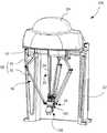
図1は、3軸の姿勢変更機構部を備えたパラレルリンクロボットの概略構成図である。パラレルリンクロボットPRは、基礎部材12と可動部材100を備えており、並列配置される3組のリンク構造により基礎部材12と可動部材100とを連結してなるパラレルメカニズム形式の可動部材駆動機構16を有し、可動部材100は基礎部材12に対して3軸並進運動のみを行う(換言すれば、3自由度のパラレルメカニズムを備えた)構成である。Hereinafter, embodiments of the present invention will be described with reference to the drawings.
FIG. 1 is a schematic configuration diagram of a parallel link robot including a three-axis posture changing mechanism unit. The parallel link robot PR includes a
本発明の一実施形態であるパラレルリンクロボットPRは、更に可動部材100に3軸の回転運動が可能な姿勢変更機構部102と、姿勢変更機構部102を可動部材100に対して3軸周りに回転させるための姿勢変更機構部駆動機構20を備えている。
基礎部材12は、パラレルリンクロボットPRの設置面に据え置かれる円弧壁状のスタンド22の上端に、側方へ水平に張り出すように固定して設けられている板状構造体から構成される。基礎部材12は、後述する可動部材駆動機構16及び姿勢変更機構部駆動機構20の構成要素群を担持する静止部材である。基礎部材12には、駆動用のモータや動力伝達機構などを覆うカバー24が、基礎部材12の上側に着脱自在に固定して取付けられている。The parallel link robot PR according to an embodiment of the present invention further includes a posture
The
可動部材駆動機構16は、互いに並列に配置される3組のリンク構造26と、それらのリンク構造26を個々に駆動する3台のサーボモータ28(図2に1台のみ示す)とを備えている。各組のリンク構造26は、複数の回転対偶(ヒンジジョイント)及び補助リンクを介して基礎部材12及び対応するサーボモータ28の出力部に関節接続される駆動リンク30と、回転対偶を介して駆動リンク30の末端に関節接続される一対の平行受動リンク32とを備える。平行受動リンク32はその末端で、回転対偶を介して可動部材100に関節接続される。 The movable
駆動リンク30は、サーボモータ28により駆動されて、基礎部材12に対して鉛直な仮想平面に沿って多彩に揺動する。平行受動リンク32は、駆動リンク30の揺動に伴い、同じ仮想平面上で変位する。このとき、1組のリンク構造26の平行受動リンク32は、可動部材100を介して他の2組のリンク構造26の平行受動リンク32に連結されているので、3組のリンク構造26の平行受動リンク32は、3つの駆動リンク30の揺動態様に応じて受動式に多彩に揺動する。 The
3組のリンク構造26は、それぞれの駆動リンク30が、基礎部材12上で互いに中心角120度ずつ離れた3箇所の固定位置で、基礎部材12に接続されるとともに、それぞれの受動リンク32が、可動部材100で互いに中心角120度ずつ離れた3箇所の固定位置で、可動部材100に接続される。その結果、可動部材駆動機構16の動作により、可動部材100は基礎部材12に対して3軸並進運動のみを遂行する。 In the three sets of
図2に示されるように、基礎部材12には、3組の可動部材駆動機構16に含まれる駆動用の3台のサーボモータ28(図2には1台のみ示す)および姿勢変更機構部駆動機構20(図2には1つのみ示す)が配置されている。基礎部材12には、カバー24側に突出する中空円筒状の座部56が形成され、ホルダ組立体50の外側ホルダ44が、回転軸受装置58の内輪が外側ホルダ44の外周面の軸線方向一端(図で下端)領域に固定される一方、回転軸受装置58の外輪が中空円筒状の取付部材60の内周面に固定され、取付部材60の座部56の軸線方向一端(図で上端)に固定される(図10参照)。 As shown in FIG. 2, the
図4は、姿勢変更機構部102の姿勢変更機構部の側面外観図である。姿勢変更機構部102は可動部材100に接続されており、姿勢変更機構部102は、3つの平行受動リンクを接続する関節部36の回転軸線を含む平面に対して垂直な第4軸線106aを中心軸としてその周りに回転可能な第1回転部材106と、第5軸線108aを中心軸としてその周りに回転可能な第2回転部材108と、第6軸線110aを中心軸としてその周りに回転可能な第3回転部材110を備えている。 FIG. 4 is a side external view of the posture changing mechanism unit of the posture changing
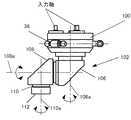
図3は、本発明の一実施形態におけるパラレルリンクロボットPRの可動部材100および姿勢変更機構部102を示す拡大斜視図である。可動部材100は、図示しない空洞部を有する円筒状部材からなり、その外周の3箇所に、可動部材駆動機構16の3組のリンク構造26の平行受動リンク32を接続する接続部104が形成される。可動部材100の空洞部には、回転軸受装置や動力伝達機構が収容され(図8参照)、可動部材100の図で姿勢変更機構部102が回転可能に支持される。 FIG. 3 is an enlarged perspective view showing the
姿勢変更機構部102は、第4軸線106aを中心として回転可能に可動部材100に接続される第1回転部材106と、第4軸線106aに直交する第5軸線108aを中心として回転可能に接続される第2回転部材108と、第5軸線108aに直交する第6軸線110aを中心として回転可能に第2回転部材108に接続される第3回転部材110とを備える。そして、第3回転部材110にツール(図示せず)を取付けるための第1フランジ面112が設けられる。姿勢変更機構部102は、平行受動リンク32を接続する関節部36の回転軸線を含む平面に対して垂直な第4軸線周りに回転可能となるように、第1回転部材が可動部材100に接続されている。 The posture changing
3個の姿勢変更機構部駆動機構20のうち、第1の姿勢変更機構部駆動機構20は、第1の自在継手80−1および歯車列等(図8参照)の動力伝達要素を介して第1回転部材106に接続される第1の伝動部材54−1を備える。第1の伝動部材54−1は、第1のサーボモータ52(図10参照)により回転駆動される第1の外側ホルダ44の回転を第1回転部材106に伝達して、第1回転部材106を第4軸線106aの周りで回転運動させる。 Of the three attitude change mechanism
3個の姿勢変更機構部駆動機構20のうち、第2の姿勢変更部駆動機構20のうち、第2の姿勢変更部駆動機構20は、第2の自在継手80−2および歯車列(図8参照)の動力伝達要素を介して第2回転部材108に接続される第2の伝動部材54−2を備える。第2の伝動部材54−2は、第2のサーボモータ52(図10参照)により回転駆動される第2の外側ホルダ44の回転を第2回転部材108に伝達して、第2回転部材108を第5軸線108aの周りで回転運動させる。 Of the three posture change mechanism
3個の姿勢変更機構部駆動機構20のうち、第3の姿勢変更部駆動機構20のうち、第3の自在継手80−3および歯車列等(図8参照)の動力伝達要素を介して第3回転部材110に接続される第3の伝動部材54−3を備える。第3の伝動部材54−3は、第3のサーボモータ52により回転駆動される第3の外側ホルダ44の回転を第3回転部材110に伝達して、第3回転部材110を第6軸線110aの周りで回転させる。第3回転部材110は、エンドエフェクタを取付けるためのフランジ面を先端に有する。
3軸周りの回転が可能な姿勢変更機構部102を備えたパラレルリンクロボットPRは、姿勢変更機構部102のフランジ面に装着されたエンドエフェクタ(図示せず)に3軸並進運動と3軸回転運動とを適宜組み合わせて遂行させることができる。Of the three attitude change
The parallel link robot PR provided with the posture changing
図3や図4に示される姿勢変更機構部102を備えたパラレルリンクロボットPRでは、平行受動リンク32を接続する各関節部36の回転軸線を含む平面と平行な平面(パラレルリンクロボットPRを床置した場合は水平面内)が、使用頻度が高い領域である。第1フランジ面112が水平になった場合は、第4軸線106aと第6軸線110aとが平行な配置関係になることから、特異点となる。特異点とは、第6軸線110aの位置を特定する場合、第4軸線106aは第6軸線110aの周りのどこかの角度位置となることから、位置の演算を行う場合に解が一義的に決められない状態という。 In the parallel link robot PR having the posture changing
そこで図5に示されるように、特異点が発生しないように、第6軸線110aとフランジ面に垂直な第7軸線112aが所定角度αを有するように、第3回転部材110に第2フランジ面を設ける。このような構造とすることで、第2フランジ面114が水平になっても、第4軸線106aと第6軸線110aとが平行にならず、使用頻度が高い水平面内が特異点となることを回避することができる。所定角度αとしては30度から60度とすると、ハンド122を取付けてハンド122に作業を行なわせるのに好適である。 Therefore, as shown in FIG. 5, the second flange surface is provided on the third
第3回転部材110に第6軸線110aと第2フランジ面114に垂直な軸線が所定角度を持つようにして第2フランジ面114を設けるシンプルな構造により、使用頻度が高い水平面内が特異点となることを回避できる。これにより、安価でコンパクトな姿勢変更機構を実現でき、各軸の動作も理解し易く、パラレルリンクロボットPRの使い勝手が格段に向上する。また、ハンドやツールの取付部に角度を付ける必要がなくなり、ハンドやツールの制作が容易になる上、安価にそれらを製造することができる。 Due to the simple structure in which the
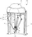
図6は、本発明の実施形態であるフランジ面を傾斜させた姿勢変更機構部を備えたパラレルリンクロボットPRの概略構成図である。傾斜した第2フランジ面を備えた姿勢変更機構部102のフランジ面に、ワークを把持しワークを移動させるなどの作業を行うハンド(図7参照)が取付けられる。 FIG. 6 is a schematic configuration diagram of a parallel link robot PR provided with a posture changing mechanism unit in which the flange surface is inclined according to the embodiment of the present invention. A hand (see FIG. 7) for performing work such as gripping and moving the workpiece is attached to the flange surface of the posture changing
水平面内に置かれたワークを把持する際は、ハンド122(図7参照)を真下に向ける必要がある。ハンド122のハンド取付部120を第2フランジ面114に装着する。前述したようにフランジ面を傾斜させた姿勢変更機構部102を用いたパラレルリンクロボットPRでは、第2フランジ面114を水平にしてハンド122を真下に向けた場合でも、第4軸線106aと第6軸線110aとは平行にならず、水平面内が特異点となることを回避できる。 When gripping a workpiece placed in a horizontal plane, the hand 122 (see FIG. 7) needs to be directed downward. The
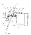
図8は、フランジ面を傾斜させた姿勢変更機構部の内部の概略構造を説明する図である。姿勢変更機構部102を回転駆動する駆動力は、おのおの独立した3つの姿勢変更機構部駆動機構20の駆動シャフト54−1,54−2,54−3により伝達される(図3参照)。この駆動力は、可動部材100上に平行受動リンク32を接続する各関節部36の軸線を含む平面に対して、垂直かつ互いに平行な軸周りに回転可能にベアリングを介して接続された入力軸に自在継手(ユニバーサルジョイント)80−1,80−2,80−3(図3参照)を介して伝達される。 FIG. 8 is a diagram illustrating a schematic structure inside the posture changing mechanism section in which the flange surface is inclined. The driving force for rotationally driving the posture
この入力軸の先端には各々ギヤ4−1,5−1,6−1(ギヤ5−1,ギヤ6−1は図示せず)が固定されている。第1回転部材106はベアリングを介して、可動部材100に対して回転可能に接続されている。第1回転部材106にはギヤ4−2が固定されており、ギヤ4−1とギヤ4−2が噛み合い、ギヤ4−1に伝達された回転駆動力がギヤ4−2に伝達され、第1回転部材106が回転する。 Gears 4-1, 5-1 and 6-1 (gears 5-1 and 6-1 are not shown) are fixed to the tips of the input shafts. The first
第1回転部材106には、ベアリングを介してギヤ5−2,5−3が回転可能に接続されている。ギヤ5−2とギヤ5−3とは駆動力を伝達できるように固定されている。ギヤ5−4は第2回転部材108に固定され、第2回転部材108はベアリングを介して回転可能に第1回転部材に接続されている。ギヤ5−1に伝達された駆動力が、ギヤ5−2、ギヤ5−3、ギヤ5−4と伝達され、第2回転部材108が回転する。また、第3回転部材110は、ギヤ6−1(図示せず)に伝達された駆動力がギヤ6−2、ギヤ6−3、ギヤ6−4、ギヤ6−5、ギヤ6−6と伝達されることによって回転する。なお、ギヤ同士
、ギヤと回転部材との固定は、動力が伝達できればよく、ボルト結合、キー結合、接着結合など、その結合手段は適宜選択して採用すればよい。Gears 5-2 and 5-3 are rotatably connected to the first rotating
図9は、姿勢変更機構部駆動機構の要部拡大断面図で、(a)ホルダ組立体を示す断面図、及び(b)ホルダ組立体を示す他の縦断面図である。姿勢変更機構部駆動機構20は、姿勢変更機構部102に取付けて可動部材100に設置されるハンド(図7参照)やツールの姿勢を制御するための駆動機構である。本発明の実施形態によるパラレルリンクロボットPRでは、3つの互いに独立して動作可能な3個の姿勢変更機構部駆動機構20を備える。基礎部材12には、図2に示す座部56と同様の3個の座部56が、3組のリンク構造26の略中心を囲む適当な位置に形成され、個々のホルダ組立体50の外側ホルダ44が対応の座部56に取付けられる。それにより、3個の姿勢変更機構部駆動機構20は、それぞれのホルダ組立体50の第1軸線44aを互いに平行に配置して構成される。 FIG. 9 is an enlarged cross-sectional view of the main part of the posture changing mechanism drive mechanism, (a) a cross-sectional view showing the holder assembly, and (b) another vertical cross-sectional view showing the holder assembly. The posture change mechanism
姿勢変更機構部駆動機構20は、3個の中空円筒状のホルダ44,46,48を互いに回転可能に、かつ3重の入れ子式に組み合わせて構成されるホルダ組立体50と、ホルダ組立体50の外側ホルダ44を回転駆動するサーボモータ52(図10参照)と、ホルダ組立体50の内側ホルダ48に直線移動(すなわち直動)可能に受容される棒状の駆動シャフト54とを備えている。 The posture changing mechanism
図9(a)に示すように、ホルダ組立体50の中間ホルダ46は、外側ホルダ44の内周面よりも径寸法の小さい外周面を有し、この外周面の互いに180度反対側の所定箇所に、径方向外方へ突出する一対の支軸62が形成される。それら支軸62は、それぞれの幾何学的中心線を互いに一致させるとともに中間ホルダ46の幾何学的中心線に直交させて配置される。他方、外側ホルダ44には、内周面の互いに180度反対側の所定箇所に、径方向へ貫通する一対の軸穴64が形成される。それら軸穴64は、それぞれの幾何学的中心軸線を互いに一致させるとともに外側ホルダ44の幾何学的中心軸線に直交させて配置される。 As shown in FIG. 9A, the
中間ホルダ46は、個々の支軸62を外側ホルダ44の対応の軸穴64に挿入して、それら軸穴64に設置される一対の回転軸受装置66を介して外側ホルダ44に取付けられる。詳細には、各回転軸受装置66の外輪が外側ホルダ44の各軸穴64の内周面に固定される。この状態で、中間ホルダ46は、それ自体の幾何学的中心軸線及び第1軸線44aの双方に直交する第2軸線46aを中心として回転可能に、外側ホルダ44に内設される。 The
図9(b)に示すように、ホルダ組立体50の内側ホルダ48は、中間ホルダ46の内周面よりも径寸法の小さい外周面を有し、この外周面の互いに180度反対側の所定箇所に、径方向外方へ突出する支軸68が形成される。それら支軸68は、それぞれの幾何学的中心線を互いに一致させるとともに内側ホルダ48の幾何学的中心軸線に直交させて配置される。他方、中間ホルダ46には、一対の支軸62から中心角90度ずれた位置で互いに180度反対側の所定箇所に、径方向へ貫通する一対の軸穴70が形成される。それら軸穴70は、それぞれの幾何学的中心軸線を互いに一致させるとともに中間ホルダ46の幾何学的中心軸線に直交させて配置される。 As shown in FIG. 9B, the
内側ホルダ48、個々の支軸68を中間ホルダ46の対応の軸穴70に挿入して、それら軸穴70に設置される一対の回転軸受装置72を介して中間ホルダ46に取付けられる。詳細には、各回転軸受装置72の内輪が内側ホルダ48の各支軸68の外周面に固定される一方、各回転軸受装置72の外輪が中間ホルダ46の各軸穴70の内周面に固定される。この状態で、内側ホルダ48は、それ自体の幾何学的中心線及び第2軸線46aの双方に直交する第3軸線48aを中心として回転可能に、中間ホルダ46に内設される。 The
外側ホルダ44には、その外周面の軸線方向他端(図で上端)に、動力伝達要素としてのギヤ74が固定され、サーボモータ52の出力軸76がギヤ74に連結される(図10参照)。サーボモータ52はギヤ74を介して外側ホルダ44を第1軸線44aの周りで回転駆動する。なお、ギヤ74の代わりにベルト及びプーリを動力伝達要素として使用することもできる。 A
駆動シャフト54は、ホルダ組立体50の内側ホルダ48の内周面よりも径寸法の小さい外周面を有する一体物の棒状要素であり、内側ホルダ48の内部に設置される直動軸受部材78を介して内側ホルダ48に取付けられる。この状態で、駆動シャフト54は、それ自体及び内側ホルダ48の幾何学的中心軸線の双方に平行で第3軸線48aに直交する直動軸54aに沿って、全長に渡り回転拘束状態で直動可能に内側ホルダ48に受容される。図示実施形態では、直動軸54aは、駆動シャフト54及び内側ホルダ48の幾何学的中心軸線に合致する。 The
駆動シャフト54を回転拘束状態で案内する直動軸受部材78は、サーボモータ52の出力を駆動シャフト54にできるだけ損失無く伝えることが、ハンドやツールの姿勢制御の精度を向上させる観点で要求される。このような直動軸受部材78として、ボールスプライン装置のスプラインシャフトを好適に使用できる。この場合、駆動シャフト54は、ボールスプライン装置のスプラインシャフトの構造を有する。ボールスプライン装置の詳細については公知であるから記載を省略する。 The linear
図10に示されるように、ホルダ組立体50は基礎部材12及びサーボモータ52の出力軸76と駆動シャフト54との間で、駆動シャフト54の幾何学的中心軸線(直動軸54a)の方向へ相対移動可能な特殊構造の自在継手として機能する。つまり、外側ホルダ44が自在継手の原動側構成部品であり、内側ホルダ48が自在継手の従動側構成部品である。したがって、駆動シャフト54は、その直動軸54aが外側ホルダ44の第1軸線44aに対し平行及び斜交するいずれの位置関係においても、サーボモータ52により駆動される外側ホルダ44の回転に同期して、直動軸54aを中心に内側ホルダ48と一体的に回転する。 As shown in FIG. 10, the
ホルダ組立体50において、外側ホルダ44に対する駆動シャフト54(つまり、第1軸線44aに対する直動軸54a)の許容傾斜角度は、外側ホルダ44、中間ホルダ46及び内側ホルダ48の相対的な位置及び寸法関係によって決まる。パラレルリンクロボットPRによる一般的な作業(ハンドリング作業)では、0度〜40度程度の範囲で駆動シャフト54が傾斜できることが望ましい。なお、3個の中空円筒状ホルダ44、46、48を3重の入れ子式に組み合わせて構成されるホルダ組立体50は、図示のように、中間ホルダ46および内側ホルダ48を外側ホルダ44の外方へ実質的に突出しないように構成できるので、要求される自在継手の能力を損なうことなくホルダ組立体50の全体寸法を比較的容易に縮小することができる。 In the
特に、パラレルリンクロボットPRでは、駆動シャフト54が、パラレルメカニズム形式の可動部材駆動機構16による可動部材100及び姿勢変更機構部102の3軸並進運動に円滑に追従して、基礎部材12及びサーボモータ52の出力軸76と駆動シャフト54との間の自在継手であるホルダ組立体に対し、直動軸54aの方向へ受動的に移動することができる。それにより、可動部材100及び姿勢変更機構部102がその作動領域内の任意の(すなわち指令された)空間位置にあるときに、サーボモータ52のトルクが姿勢変更機構部102に確実に伝達される。 In particular, in the parallel link robot PR, the
ここで、前述したように、可動部材駆動機構16は、可動部材100を基礎部材12に対して3軸並進運動のみを遂行するように駆動するから、可動部材駆動機構16が動作する間、姿勢変更機構部102の入力軸は常に、ホルダ組立体50の第1軸線44aに対して平行に配置される。その結果、基礎部材12に対する駆動シャフト54の傾斜角度によらず、外側ホルダ44の角速度と姿勢変更機構部102の入力軸の各速度とが互いに一致する。 Here, as described above, the movable
上記構成では、駆動シャフト54は、可動部材100及び姿勢変更機構部102の3軸並進運動に追従して、基礎部材12に担持されるホルダ組立体50の外側ホルダ44の上方へ、多様な角度で多様な長さに渡り延出する。したがって、姿勢変更機構部駆動機構20のサーボモータ52は、外側ホルダ44に隣接した位置で、外側ホルダ44よりも可動部材100から離れる方向へは突出しないように基礎部材12に担持されることが、サーボモータ52と駆動シャフト54との相互干渉を回避する観点で有利である(図10参照)。 In the above configuration, the
PR パラレルリンクロボット
12 基礎部材
16 可動部材駆動機構
20 姿勢変更機構部駆動機構
26 リンク構造
28 サーボモータ
30 駆動リンク
32 受動リンク
52 サーボモータ
54 駆動シャフト
100 可動部材
102 姿勢変更機構部
106 第1回転部材
106a 第4軸線
108 第2回転部材
108a 第5軸線
110 第3回転部材
110a 第6軸線
112 第1フランジ面
114 第2フランジ面PR
Claims (1)
Translated fromJapanese前記フランジ面に垂直な軸線が前記第6軸線と所定の角度をもって交わり、
前記第1回転部材、前記第2回転部材、および前記第3回転部材をそれぞれ前記第4軸線、前記第5軸線、および前記第6軸線回りに回転駆動する3つのモータは前記基礎部材に配置され、
前記可動部材には3つの入力軸が設けられ、
前記3つの入力軸は、前記可動部材と3つの前記受動リンクを接続する各関節部の回転軸線を含む平面に対して垂直かつ互いに平行な軸であって、
3つの前記モータからの各駆動力を伝達する3本の独立した駆動シャフトは、前記3つの入力軸のそれぞれの軸回りに回転出来るように連結され、
3つの前記モータからの各駆動力は、前記姿勢変更機構部に配置されたギヤを介して、前記第4軸線回り、前記第5軸線回り、前記第6軸線回りに前記第1回転部材、前記第2回転部材、前記第3回転部材を駆動することを特徴とするパラレルリンクロボット。A posture changing mechanism having three degrees of freedom for jointly connecting three sets of link mechanisms including a drive link and a passive link between the base member and the movable member to control the posture of the end effector to the movable member. In the parallel link robot comprising: the movable member connected to the movable member so as to be rotatable around a fourth axis perpendicular to a plane including a rotation axis of each joint portion connecting the movable member and the three passive links. A first rotating member; a second rotating member connected to the first rotating member so as to be rotatable about a fifth axis orthogonal to the fourth axis; and the second rotating member orthogonal to the fifth axis A third rotating member that is rotatably connected around the sixth axis and has a flange surface at the tip for attaching the end effector,
Ri Majiwa an axis perpendicular to said flange surface with the sixth axis at a predeterminedangle,
Three motors for rotating the first rotating member, the second rotating member, and the third rotating member around the fourth axis, the fifth axis, and the sixth axis, respectively, are disposed on the base member. ,
The movable member is provided with three input shafts,
The three input shafts are axes perpendicular to and parallel to a plane including a rotation axis of each joint portion connecting the movable member and the three passive links,
Three independent drive shafts for transmitting each drive force from the three motors are connected so as to be able to rotate around respective axes of the three input shafts,
The driving forces from the three motors are arranged around the fourth axis, around the fifth axis, around the sixth axis via the gears arranged in the posture changing mechanism, the second rotating member, parallel robot characterized thatyou drive the third rotary member.
Priority Applications (5)
| Application Number | Priority Date | Filing Date | Title |
|---|---|---|---|
| JP2009030876AJP4659098B2 (en) | 2009-02-13 | 2009-02-13 | Parallel link robot with posture change mechanism with 3 degrees of freedom |
| CN201010115657.4ACN101804631B (en) | 2009-02-13 | 2010-02-11 | Parallel robot provided with wrist section having three degrees of freedom |
| US12/704,027US8109173B2 (en) | 2009-02-13 | 2010-02-11 | Parallel robot provided with wrist section having three degrees of freedom |
| DE102010007631.7ADE102010007631B4 (en) | 2009-02-13 | 2010-02-11 | Parallel robot with a wrist section with three degrees of freedom |
| US13/238,199US8893578B2 (en) | 2009-02-13 | 2011-09-21 | Parallel robot provided with wrist section having three degrees of freedom |
Applications Claiming Priority (1)
| Application Number | Priority Date | Filing Date | Title |
|---|---|---|---|
| JP2009030876AJP4659098B2 (en) | 2009-02-13 | 2009-02-13 | Parallel link robot with posture change mechanism with 3 degrees of freedom |
Related Child Applications (1)
| Application Number | Title | Priority Date | Filing Date |
|---|---|---|---|
| JP2010278173ADivisionJP5394358B2 (en) | 2010-12-14 | 2010-12-14 | Parallel link robot with posture change mechanism with 3 degrees of freedom |
Publications (2)
| Publication Number | Publication Date |
|---|---|
| JP2010184328A JP2010184328A (en) | 2010-08-26 |
| JP4659098B2true JP4659098B2 (en) | 2011-03-30 |
Family
ID=42558742
Family Applications (1)
| Application Number | Title | Priority Date | Filing Date |
|---|---|---|---|
| JP2009030876AActiveJP4659098B2 (en) | 2009-02-13 | 2009-02-13 | Parallel link robot with posture change mechanism with 3 degrees of freedom |
Country Status (4)
| Country | Link |
|---|---|
| US (1) | US8109173B2 (en) |
| JP (1) | JP4659098B2 (en) |
| CN (1) | CN101804631B (en) |
| DE (1) | DE102010007631B4 (en) |
Cited By (5)
| Publication number | Priority date | Publication date | Assignee | Title |
|---|---|---|---|---|
| KR101483081B1 (en) | 2014-01-16 | 2015-01-21 | 주식회사 로보스타 | Parallel robot wrist using differential gear |
| WO2018008491A1 (en) | 2016-07-08 | 2018-01-11 | Sony Corporation | Parallel link device, industrial robot, and haptic presentation device |
| US10427294B2 (en) | 2014-08-06 | 2019-10-01 | Sony Corporation | Parallel link robot and parallel link structure |
| KR102129337B1 (en) | 2020-02-10 | 2020-07-02 | 재단법인 구미전자정보기술원 | A micro-module laparoscopic surgery robot |
| KR20210059128A (en) | 2019-11-14 | 2021-05-25 | 중앙대학교 산학협력단 | Underactuation mechanism of wrist and forearm which is capable of fullyindependent motion in each degrees of freedom |
Families Citing this family (62)
| Publication number | Priority date | Publication date | Assignee | Title |
|---|---|---|---|---|
| US8768516B2 (en)* | 2009-06-30 | 2014-07-01 | Intuitive Surgical Operations, Inc. | Control of medical robotic system manipulator about kinematic singularities |
| DE102006046758A1 (en)* | 2006-09-29 | 2008-04-03 | Abb Patent Gmbh | Arrangement, especially for positioning objects, has at least one pair of supports made up of two supports that run parallel one inside the other and together form parallelogram |
| JP4598864B2 (en)* | 2009-01-29 | 2010-12-15 | ファナック株式会社 | Parallel robot |
| US8893578B2 (en)* | 2009-02-13 | 2014-11-25 | Fanuc Corporation | Parallel robot provided with wrist section having three degrees of freedom |
| DE102009017907A1 (en)* | 2009-04-17 | 2010-10-21 | Weber Maschinenbau Gmbh Breidenbach | Robot with delta kinematics |
| CN101708611B (en)* | 2009-11-09 | 2011-07-27 | 天津大学 | Parallel mechanism with three-dimensional translation and one-dimensional rotation |
| CN102069499B (en)* | 2009-11-19 | 2013-08-28 | 鸿富锦精密工业(深圳)有限公司 | Parallel robot |
| IT1399603B1 (en)* | 2010-04-26 | 2013-04-26 | Scuola Superiore Di Studi Universitari E Di Perfez | ROBOTIC SYSTEM FOR MINIMUM INVASIVE SURGERY INTERVENTIONS |
| JP5394358B2 (en)* | 2010-12-14 | 2014-01-22 | ファナック株式会社 | Parallel link robot with posture change mechanism with 3 degrees of freedom |
| TWI415724B (en)* | 2010-12-22 | 2013-11-21 | Ind Tech Res Inst | Parallel robot and wrist module |
| KR101164378B1 (en)* | 2011-06-07 | 2012-07-09 | 양국진 | Parallel manipulator |
| DE102011105616A1 (en)* | 2011-06-28 | 2013-01-03 | Jozef Ezechias | Hybrid robot based on three linear axes whose axes intersect, a parellelity holder, a multifunctional space joint, a multi-axis space joint and a space orientation unit |
| JP5454524B2 (en)* | 2011-07-15 | 2014-03-26 | 株式会社安川電機 | Parallel link robot and picking system |
| SG11201402020XA (en)* | 2011-11-04 | 2014-09-26 | Univ Johns Hopkins | Steady hand micromanipulation robot |
| JP5475747B2 (en)* | 2011-12-07 | 2014-04-16 | Thk株式会社 | Parallel link robot |
| CN104520075B (en) | 2012-08-09 | 2017-03-15 | 富士通株式会社 | robot |
| CN102848375A (en)* | 2012-08-29 | 2013-01-02 | 江西省机械科学研究所 | Spatial six-degree-of-freedom mechanism capable of separately controlling rotation motion and translation motion |
| JP5674734B2 (en)* | 2012-08-31 | 2015-02-25 | ファナック株式会社 | Parallel link robot connected by ball joint |
| CN102837308A (en)* | 2012-09-26 | 2012-12-26 | 广州达意隆包装机械股份有限公司 | Robot |
| DE112013004847A5 (en)* | 2012-10-02 | 2015-06-11 | Majatronic Gmbh | industrial robot |
| MX341585B (en)* | 2013-02-14 | 2016-08-25 | Automatische Technik México S A De C V * | Delta-type industrial robot. |
| JP5682642B2 (en)* | 2013-03-05 | 2015-03-11 | 株式会社安川電機 | Parallel link robot |
| CN103240729B (en)* | 2013-04-23 | 2015-04-29 | 天津大学 | Telescopic space triple-translation parallel manipulator |
| KR101401463B1 (en) | 2013-05-16 | 2014-05-30 | 주식회사 엔티리서치 | Parallel link robot providing additional degree of freedom by wire rope |
| JP5849993B2 (en)* | 2013-06-07 | 2016-02-03 | 株式会社安川電機 | Parallel link robot, robot system, and transfer equipment construction method |
| KR101483080B1 (en)* | 2013-11-07 | 2015-01-16 | 주식회사 로보스타 | Rectangular coordinate robot combined with 3 degrees of freedom wrist structure |
| CN103640011B (en)* | 2013-11-26 | 2015-10-14 | 东莞华中科技大学制造工程研究院 | Three Degree Of Freedom wrist and Novel six freedom DELTA robot |
| JP5949799B2 (en)* | 2014-01-24 | 2016-07-13 | 株式会社安川電機 | Parallel link robot, parallel link robot hand and parallel link robot system |
| KR101520451B1 (en)* | 2014-02-13 | 2015-05-14 | 주식회사 로보스타 | Desktop type rectangular coordinate robot combined with 3-degrees of freedom wrist device |
| CN103878786B (en)* | 2014-04-04 | 2015-12-02 | 浙江钱江摩托股份有限公司 | A kind of wrist with Three Degree Of Freedom of robot |
| CN103895031B (en)* | 2014-04-04 | 2015-12-02 | 浙江钱江摩托股份有限公司 | A kind of robot wrist with Three Degree Of Freedom |
| CN104260080B (en)* | 2014-09-19 | 2016-08-24 | 江南大学 | The built-in parallel robot of Three Degree Of Freedom bar |
| DE102014223389A1 (en)* | 2014-11-17 | 2016-05-19 | Krones Aktiengesellschaft | Device and method for handling articles such as containers, piece goods or the like |
| DE102014223393A1 (en)* | 2014-11-17 | 2016-05-19 | Krones Aktiengesellschaft | Method for handling and / or manipulating articles such as containers or piece goods |
| DE102014223410B4 (en) | 2014-11-17 | 2017-03-16 | Krones Aktiengesellschaft | Device and method for handling articles such as containers, piece goods or the like |
| CN104369183A (en)* | 2014-11-19 | 2015-02-25 | 苏州赛腾精密电子有限公司 | Multidirectional mechanical arm |
| CN104493831A (en)* | 2014-12-23 | 2015-04-08 | 东莞市顺如电子科技有限公司 | Full-range parallel four-joint control device |
| US10507576B2 (en)* | 2015-09-24 | 2019-12-17 | Autonox Robotics Gmbh | Industrial robot |
| DE102015220413A1 (en)* | 2015-10-20 | 2017-04-20 | Krones Aktiengesellschaft | Parallel kinematic robot and method of handling same |
| DE102015220357A1 (en)* | 2015-10-20 | 2017-04-20 | Krones Aktiengesellschaft | Parallel kinematic robot and method of operating such |
| JP2017170540A (en)* | 2016-03-18 | 2017-09-28 | 株式会社タダノ | Profiling device |
| EP3481598B1 (en) | 2016-07-07 | 2020-09-02 | ABB Schweiz AG | A base for a parallel kinematics robot |
| CN106239482A (en)* | 2016-08-31 | 2016-12-21 | 上海交通大学 | Six degree of freedom Delta sorting machine people |
| JP6856447B2 (en)* | 2017-05-24 | 2021-04-07 | ファナック株式会社 | Control device and control method of parallel link mechanism, and system including parallel link mechanism and control device |
| JP6955905B2 (en)* | 2017-05-29 | 2021-10-27 | コマニー株式会社 | Robot hand for parallel link robot and parallel link robot |
| CN107081760B (en)* | 2017-06-21 | 2023-05-09 | 东莞爱创机器人科技有限公司 | Six-degree-of-freedom mechanical arm based on translation parallel mechanism |
| MX2020001486A (en) | 2017-08-07 | 2020-03-20 | Pharmaq As | Live fish processing system, and associates method. |
| DE102017123838A1 (en)* | 2017-10-13 | 2019-04-18 | Hartmut Ilch | industrial robots |
| KR102009291B1 (en)* | 2017-10-13 | 2019-08-09 | 한국기술교육대학교 산학협력단 | Apparatus of robot joint |
| KR101983563B1 (en)* | 2017-11-23 | 2019-05-29 | (주)한국미래기술 | Parallel type integrated actuator |
| CN107972017A (en)* | 2017-12-29 | 2018-05-01 | 勃肯特(天津)机器人技术有限公司 | Six axis serial-parallel mirror robots |
| CN111989191B (en)* | 2018-04-24 | 2023-07-11 | Abb瑞士股份有限公司 | Parallel Motion Robot |
| JP6823007B2 (en)* | 2018-04-27 | 2021-01-27 | ファナック株式会社 | Parallel link robot |
| CN109318252B (en)* | 2018-10-24 | 2024-04-12 | 上海机器人产业技术研究院有限公司 | Wrist with three degrees of freedom and kinematic calculation method thereof |
| CN109533458A (en)* | 2018-12-21 | 2019-03-29 | 广东赛德英斯智能装备有限公司 | A kind of soft device for touching grasping means and realizing this method of type self-adapting type article |
| CN110231010B (en)* | 2019-04-26 | 2021-07-13 | 合肥工业大学 | A three-coordinate measuring machine and measuring method based on Delta parallel mechanism |
| JP6774540B1 (en)* | 2019-08-07 | 2020-10-28 | 株式会社バンダイ | Joint structure and doll body |
| CN112887573B (en)* | 2021-01-28 | 2024-02-27 | 维沃移动通信有限公司 | Camera assembly and electronic equipment |
| US12318157B2 (en)* | 2021-11-23 | 2025-06-03 | Mazor Robotics Ltd. | Multiple end effector interfaces coupled with different kinematics |
| CN114906249B (en)* | 2022-06-10 | 2024-02-02 | 中国人民解放军国防科技大学 | A twelve-degree-of-freedom parallel bionic quadruped robot |
| US20250073918A1 (en)* | 2022-11-28 | 2025-03-06 | Shanghai Flexiv Robotics Technology Co., Ltd. | Parallel robot |
| CN118322173A (en)* | 2024-05-14 | 2024-07-12 | 天津工业大学 | Terminal hinged parallel mechanism capable of realizing three-degree-of-freedom or four-degree-of-freedom mode |
Family Cites Families (19)
| Publication number | Priority date | Publication date | Assignee | Title |
|---|---|---|---|---|
| DE2226407C3 (en)* | 1972-05-31 | 1978-10-12 | Industrie-Werke Karlsruhe Augsburg Ag, 7500 Karlsruhe | Device for automated handouts that can be controlled by modifiable programs |
| DE3048067C2 (en)* | 1980-12-19 | 1984-08-09 | Kuka Schweissanlagen + Roboter Gmbh, 8900 Augsburg | Gear arrangement for the joint head of a manipulator |
| JPS60114489A (en)* | 1983-11-22 | 1985-06-20 | 株式会社安川電機 | Industrial robot wrist mechanism |
| JPS60172491A (en)* | 1984-02-14 | 1985-09-05 | 三菱電機株式会社 | Industrial robot hand device |
| CH672089A5 (en)* | 1985-12-16 | 1989-10-31 | Sogeva Sa | |
| JPH0752004B2 (en) | 1990-06-11 | 1995-06-05 | 東レエンジニアリング株式会社 | Organic matter removal method by fluidized bed furnace |
| JPH06226680A (en)* | 1993-02-05 | 1994-08-16 | Hirotec:Kk | Robot wrist structure |
| FR2702373B1 (en) | 1993-03-08 | 1996-06-07 | Rhone Merieux | Water-in-oil fluid vaccine emulsions containing a metabolizable oil. |
| JP2000046140A (en)* | 1998-07-31 | 2000-02-18 | Yaskawa Electric Corp | Electric cylinder and parallel link robot |
| JP2001038671A (en)* | 1999-08-02 | 2001-02-13 | Denso Corp | Articulated robot |
| JP4632560B2 (en)* | 2000-03-01 | 2011-02-16 | シーグ パック システムズ アクチェンゲゼルシャフト | Robots that operate products in a three-dimensional space |
| US6896473B2 (en)* | 2001-09-17 | 2005-05-24 | Robert Bosch Gmbh | Device for transmitting torque |
| CN1269619C (en)* | 2003-11-28 | 2006-08-16 | 清华大学 | Spatial five freedom degree parallel robot mechanism |
| DE102004033329B4 (en)* | 2004-07-09 | 2007-08-16 | Dürr Systems GmbH | Application robot with parallel kinematics |
| EP1851611A1 (en)* | 2005-02-11 | 2007-11-07 | Force Dimension S.à.r.l | Device for transmitting movements and components thereof |
| FR2900857B1 (en)* | 2006-05-11 | 2008-10-17 | Jean Marie Chenu | MANIPULATOR ROBOT |
| JP2008264904A (en)* | 2007-04-17 | 2008-11-06 | Fanuc Ltd | Parallel-link working device |
| JP2008286363A (en)* | 2007-05-21 | 2008-11-27 | Fanuc Ltd | Four-degree-of-freedom restriction braking device, and parallel link type robot |
| JP4598864B2 (en)* | 2009-01-29 | 2010-12-15 | ファナック株式会社 | Parallel robot |
- 2009
- 2009-02-13JPJP2009030876Apatent/JP4659098B2/enactiveActive
- 2010
- 2010-02-11DEDE102010007631.7Apatent/DE102010007631B4/enactiveActive
- 2010-02-11CNCN201010115657.4Apatent/CN101804631B/enactiveActive
- 2010-02-11USUS12/704,027patent/US8109173B2/enactiveActive
Cited By (6)
| Publication number | Priority date | Publication date | Assignee | Title |
|---|---|---|---|---|
| KR101483081B1 (en) | 2014-01-16 | 2015-01-21 | 주식회사 로보스타 | Parallel robot wrist using differential gear |
| US10427294B2 (en) | 2014-08-06 | 2019-10-01 | Sony Corporation | Parallel link robot and parallel link structure |
| WO2018008491A1 (en) | 2016-07-08 | 2018-01-11 | Sony Corporation | Parallel link device, industrial robot, and haptic presentation device |
| US11230018B2 (en) | 2016-07-08 | 2022-01-25 | Sony Corporation | Parallel link device, industrial robot, and haptic presentation device |
| KR20210059128A (en) | 2019-11-14 | 2021-05-25 | 중앙대학교 산학협력단 | Underactuation mechanism of wrist and forearm which is capable of fullyindependent motion in each degrees of freedom |
| KR102129337B1 (en) | 2020-02-10 | 2020-07-02 | 재단법인 구미전자정보기술원 | A micro-module laparoscopic surgery robot |
Also Published As
| Publication number | Publication date |
|---|---|
| DE102010007631A8 (en) | 2011-04-21 |
| CN101804631B (en) | 2012-08-08 |
| CN101804631A (en) | 2010-08-18 |
| US20100206120A1 (en) | 2010-08-19 |
| US8109173B2 (en) | 2012-02-07 |
| JP2010184328A (en) | 2010-08-26 |
| DE102010007631A1 (en) | 2011-01-05 |
| DE102010007631B4 (en) | 2014-03-27 |
Similar Documents
| Publication | Publication Date | Title |
|---|---|---|
| JP4659098B2 (en) | Parallel link robot with posture change mechanism with 3 degrees of freedom | |
| JP4598864B2 (en) | Parallel robot | |
| US8893578B2 (en) | Parallel robot provided with wrist section having three degrees of freedom | |
| JP5394358B2 (en) | Parallel link robot with posture change mechanism with 3 degrees of freedom | |
| JP5403303B2 (en) | Parallel mechanism | |
| JP5546826B2 (en) | Joint structure for multi-axis robot and robot having such joint structure | |
| EP2152477B1 (en) | Robotic manipulator using rotary drives | |
| JP6729855B2 (en) | Multi-directional driving device, robot joint mechanism, and multi-directional driving method | |
| JP4696384B2 (en) | Parallel link robot | |
| JP2010247280A (en) | Multi-degree-of-freedom robot | |
| WO2019098273A1 (en) | Multidirectional drive device, robot joint mechanism, and multidirectional drive method | |
| CN102049784A (en) | Industrial robot | |
| JP2013094920A (en) | Joint mechanism and work attachment | |
| CN111168645A (en) | Parallel connecting rod robot | |
| JP2005127475A (en) | Link operating device | |
| WO2022163789A1 (en) | Arm robot | |
| JP7332337B2 (en) | parallel link robot | |
| JP2021084208A (en) | Parallel link robot | |
| KR100774887B1 (en) | Triaxial joint device of manipulator | |
| JP2020146810A (en) | Robot arm | |
| JP2018167365A (en) | Robot arm | |
| WO2019078283A1 (en) | Double-arm-type operation device | |
| JP2019077031A (en) | Double-arm working device | |
| JP2013013991A (en) | Parallel link robot | |
| JPS6229194B2 (en) |
Legal Events
| Date | Code | Title | Description |
|---|---|---|---|
| A131 | Notification of reasons for refusal | Free format text:JAPANESE INTERMEDIATE CODE: A131 Effective date:20100615 | |
| A521 | Request for written amendment filed | Free format text:JAPANESE INTERMEDIATE CODE: A523 Effective date:20100728 | |
| A131 | Notification of reasons for refusal | Free format text:JAPANESE INTERMEDIATE CODE: A131 Effective date:20100817 | |
| A521 | Request for written amendment filed | Free format text:JAPANESE INTERMEDIATE CODE: A523 Effective date:20100917 | |
| TRDD | Decision of grant or rejection written | ||
| A01 | Written decision to grant a patent or to grant a registration (utility model) | Free format text:JAPANESE INTERMEDIATE CODE: A01 Effective date:20101214 | |
| A01 | Written decision to grant a patent or to grant a registration (utility model) | Free format text:JAPANESE INTERMEDIATE CODE: A01 | |
| A61 | First payment of annual fees (during grant procedure) | Free format text:JAPANESE INTERMEDIATE CODE: A61 Effective date:20101224 | |
| FPAY | Renewal fee payment (event date is renewal date of database) | Free format text:PAYMENT UNTIL: 20140107 Year of fee payment:3 | |
| R150 | Certificate of patent or registration of utility model | Ref document number:4659098 Country of ref document:JP Free format text:JAPANESE INTERMEDIATE CODE: R150 Free format text:JAPANESE INTERMEDIATE CODE: R150 |