JP4656756B2 - Helmet shield plate control device - Google Patents
Helmet shield plate control deviceDownload PDFInfo
- Publication number
- JP4656756B2 JP4656756B2JP2001149630AJP2001149630AJP4656756B2JP 4656756 B2JP4656756 B2JP 4656756B2JP 2001149630 AJP2001149630 AJP 2001149630AJP 2001149630 AJP2001149630 AJP 2001149630AJP 4656756 B2JP4656756 B2JP 4656756B2
- Authority
- JP
- Japan
- Prior art keywords
- shield plate
- lock
- fully closed
- control lever
- helmet
- Prior art date
- Legal status (The legal status is an assumption and is not a legal conclusion. Google has not performed a legal analysis and makes no representation as to the accuracy of the status listed.)
- Expired - Fee Related
Links
Images


Classifications
- A—HUMAN NECESSITIES
- A42—HEADWEAR
- A42B—HATS; HEAD COVERINGS
- A42B3/00—Helmets; Helmet covers ; Other protective head coverings
- A42B3/04—Parts, details or accessories of helmets
- A42B3/18—Face protection devices
- A42B3/22—Visors
- A42B3/221—Attaching visors to helmet shells, e.g. on motorcycle helmets
- A42B3/222—Attaching visors to helmet shells, e.g. on motorcycle helmets in an articulated manner, e.g. hinge devices
- A42B3/223—Attaching visors to helmet shells, e.g. on motorcycle helmets in an articulated manner, e.g. hinge devices with means for locking the visor in a fully open, intermediate or closed position
Landscapes
- Helmets And Other Head Coverings (AREA)
Description
Translated fromJapanese【0001】
【産業上の利用分野】
本発明は,帽体とそれに枢支されるシールド板との間に設けられて,シールド板を全閉位置,全開位置及び複数の中間開度位置に保持し得るクリックストップ機構と,帽体に軸支されて,帽体の全閉を許容する中立位置及び,全閉位置のシールド板を押し上げて微小開度に開く微開位置の間を回動し得る制御レバーとを備える,主として車両の乗員が装着するヘルメットのシールド板制御装置に関し,特に,シールド板を全閉位置に拘束し得るロック手段を備えるものゝ改良に関する。
【0002】
【従来の技術】
かゝるヘルメットのシールド板制御装置において,シールド板を全閉位置に拘束し得るロック手段を備えるものは,例えば特開平5−214604号公報に開示されているように,既に知られたいる。
【0003】
【発明が解決しようとする課題】
ところで,従来の装置は,上記公報に開示されるように,シールド板の内側面に係止孔を形成する一方,その係止孔に係合してシールド板を全閉位置にロックするロックピンを帽体に固設し,制御レバーを中立位置から微開位置へ回動するとき,該レバーに形成されたカムによりシールド板を内側から掬い上げて係止シールド板の係止孔を帽体のロックピンから離脱させるようになっおり,こうしたものでは,係止シールド板の係止孔を帽体のロックピンから離脱させるべく,制御レバーを中立位置から微開位置へ回動する度に,カムがシールド板の内側面を強く擦ることになるから,長期間の使用中,両者の擦れ合う部分が摩耗すると,係止孔のロックピンからの離脱が困難となる可能性がある。
【0004】
本発明は,かゝる事情に鑑みてなされたもので,制御レバーを利用して,強く擦れ合う部分を持たずに,シールド板の全閉位置での拘束及び拘束解除を長期間的確に行い得るようにした,ヘルメットのシールド板制御装置を提供することを目的とする。
【0005】
【課題を解決するための手段】
上記目的を達成するために,本発明は,帽体とそれに枢支されるシールド板との間に設けられて,シールド板を全閉位置,全開位置及び複数の中間開度位置に保持し得るクリックストップ機構と,帽体に軸支されて,帽体の全閉を許容する中立位置及び,全閉位置のシールド板を押し上げて微小開度に開く微開位置の間を回動し得る制御レバーとを備える,ヘルメットのシールド板制御装置において,前記制御レバーに,それを中立位置から微開位置と反対方向へ回動して得るロック位置を与え,シールド板の内側面に当接突起を形成する一方,前記制御レバーに,シールド板が全閉位置にあるとき該制御レバーを前記ロック位置に回動すると,前記当接突起の前面に当接してシールド板の開放を阻止するロック爪を形成したことを第1の特徴とする。
【0006】
この第1の特徴によれば,シールド板を全閉状態にしてから,制御レバーをロック位置にセットすると,そのロック爪がシールド板内面の当接突起の前面に当接してシールド板を全閉位置に拘束することができる。しかも制御レバーによるシールド板の拘束及び拘束解除に際しては,当接突起及びロック爪は,単に相互に当接,離間するのみで,擦れ合うことがないから,長期間の使用によるも摩耗することがなく,したがって常にシールド板の拘束及び拘束解除を的確に行うことができる。
【0007】
また本発明は,第1の特徴に加えて,前記ロック爪には,前記制御レバーがロック位置にあるとき,シールド板を開放位置から全閉位置まで回動すると,前記当接突起に押圧されて該制御レバーを中立位置に回動させる斜面を形成したことを第2の特徴とする。
【0008】
この第2の特徴によれば,先に制御レバーをロック位置にセットし,次いでシールド板を全閉位置まで回動する場合でも,当接突起がロック爪上部の斜面を押圧して制御レバーを中立位置に戻すことができるので,ロック爪に邪魔されることなくシールド板を確実に全閉状態にすることができる。
【0009】
さらに本発明は,第1又は第2の特徴に加えて,前記当接突起を,前記クリックストップ機構の,シールド板内面に形成されたクリック歯を有する歯形壁に一体に連設したことを第3の特徴とする。
【0010】
この第3の特徴によれば,当接突起は,比較的大きい歯形壁により効果的に補強されることになり,シールド板の全閉位置での拘束強度を高めることができる。
【0011】
【発明の実施の形態】
本発明の実施の形態を,添付図面に示す本発明の一実施例に基づいて以下に説明する。
【0012】
図1は本発明のシールド板制御装置を備えたヘルメットの側面図,図2は図1の一部破断拡大側面図,図3は同ヘルメットの要部分解斜視図,図4は図2の4−4線断面図,図5は図2の5−5線断面図,図6は同ヘルメットの,シールド板全開状態での要部拡大側面図,図7は図6の7−7線断面図,図8は図6の8−8線断面図,図9はシールド板の取外し方を説明する同ヘルメットの要部拡大側面図,図10は図9の10−10線断面図,図11は図2の11−11線断面図,図12は図2の12−12線断面図,図13は図12の13−13線断面図で制御レバーの非作動状態を示す,図14は制御レバーによるシールド板の微開状態を示す図13との対応図,図15は制御レバーによるシールド板の全閉ロック状態を示す図13との対応図である。
【0013】
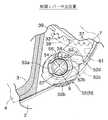
先ず図1において,符号1は自動二輪車のライダ用フルフェース型ヘルメット1を示し,その帽体2の左右両側壁には,その前壁に開口する窓3を開閉するシールド板4の左右両端部が上下方向回動可能に取り付けられる。シールド板4は両端部を含む全体が透明若しくは透光性の合成樹脂を材料として成形されている。
【0014】
図2及び図3に示すように,帽体2の左右外側面には浅い凹部6が形成されており,この凹部6底面に合成樹脂製のブラケット板7が上下二個所をビス8,9により固着される。
【0015】
図2〜図5に示すように,上記ブラケット板7の表面には支筒10が上部のビス8を囲繞するように一体に形成される。この支筒10の内壁上部には幅広の扇形凹部11が,また同支筒10の下部には幅狭の切欠12がそれぞれ設けられ,扇形凹部11の中央部上縁には庇状の仮止め突起13(図3及び図7参照)が形成される。さらに支筒10の内壁には,扇形凹部11の前端から下方へ延びる案内溝14と,切欠12の後端から上方へ延びる案内溝15とが設けられる。
【0016】
またブラケット板7には,支筒10と同心の円弧状の案内突壁16が支筒10から前方及び下方へ間隔を存して形成され,この案内突壁16の上部に切欠17が設けられる。また,この案内突壁16は,その外周面に係止溝18を備えている。
【0017】
前記支筒10及び案内突壁16間にロックレバー19が配設され,該レバー19と一体の支軸20は,前記両切欠12,17間でブラケット板7に穿設された軸孔21に回転自在に嵌合される。
【0018】
ロックレバー19は,支軸20から上方へ延びる上部腕19aと,下部後方へ延びる下部腕19bとを有して弓形をなしており,下部腕19bには支筒10の切欠12に出入する第1ロック爪23が,また上部腕19aには案内突壁16の切欠17に出入する第2ロック爪24がそれぞれ設けられる。これら第1及び第2ロック爪23,24の先端外側縁部はそれぞれ斜面23a,24a(図3)に形成される。
【0019】
下部腕19bの先端には,輪状のノブ25が,また上部腕19aの先端には案内爪26がそれぞれ形成される。
【0020】
この案内爪26は支軸20を中心とする円弧状をなしていて,ブラケット板7の,軸孔21を中心とした弧状の案内孔27に係合(図5参照)することにより,ロックレバー19のブラケット板7からの離脱を防止する。また案内爪26は,案内孔27の一端壁と他端壁とに当接することにより,ロックレバー19のロック位置Lとアンロック位置ULを規制する。而して,ロックレバー19のロック位置L(図6参照)では第1及び第2ロック爪23,24が前記切欠12,17にそれぞれ進入し,アンロック位置UL(図9参照)では第1及び第2ロック爪23,24が同切欠12,17からそれぞれ退出するようになっている。
【0021】
ブラケット板7及びロックレバー19間には,該レバー19をロック位置Lに向けて付勢するロックスプリング28(図7参照)が縮設される。
【0022】
さらにロックレバー19の離脱防止を図るために,該レバー19及び支筒10に,該レバー19がロック位置Lを占めるとき互いに係合する突起29と凹部30(図3参照)がそれぞれ形成される。
【0023】
さらにブラケット板7には,案内突壁17の前方で弾性腕31の両端が一体に結合される。この弾性腕31は中央部前面に一枚または複数枚の固定クリック歯32を備えている。
【0024】
一方,シールド板4の左右各端部内面には,前記支筒10に遊嵌する枢軸33が一体に突設される。この枢軸33の外周には,前記扇形凹部11及び切欠12を通して前記案内溝14,15に係合し得る係止爪34,35が形成され,これら係止爪34,35の外周縁部は,仮止め突起13及び第1ロック爪23の斜面23aにそれぞれ摺接し得る斜面34a,35a(図3参照)になっている。
【0025】
またシールド板4の左右各端部内面には,前記案内突壁16の切欠17を通して前記案内溝18に係合し得る係止爪36が形成され,この係止爪36の先端部一側面にも,前記第2ロック爪24の斜面24aに摺接し得る斜面36a(図3参照)が形成される。
【0026】
さらにシールド板4には,前記弾性腕31の弾性力をもって固定クリック歯32と係合する多数のクリック歯37,37…を内周面に突設した歯形壁38が一体に形成され,この歯形壁38は前記枢軸33を中心とした円弧をなしている。而して,弾性腕31及び突壁38は,シールド板4を多段の回動位置で停止させるクリックストップ機構39を構成する。
【0027】
シールド板4の全開位置は,係止爪36が前記切欠17の上端壁即ちストッパ壁40に当接することにより規制される。この全開位置がシールド板4の着脱位置であって,係止爪34が扇形凹部11に,係止爪35が切欠12に,係止爪36が切欠17に合致するようになっている。
【0028】
シールド板4を帽体2に取り付けるには,図6に示すように,シールド板4の全開位置でシールド板4の枢軸33をブラケット板7の支筒10に整合させると,枢軸33の係止爪34,35が支筒10の扇形凹部11及び切欠12への進入可能位置に,また別の係止爪36が案内突壁16の切欠17への進入可能位置にくる。
【0029】
そこで,先ずシールド板4の端部を僅かに握って係止爪34を仮止め突起13の下に潜らせながら支筒10の扇形凹部11に進入させ(図10の状態参照),次いでシールド板4の端部をブラケット板7に向って強く押圧すると,係止爪35は,その斜面35aでロックレバー19の第1ロック爪23の斜面23aを一旦押し退けながら支筒10の切欠12に進入し,残る係止爪36も,その斜面36aで第2ロック爪24の斜面24aを一旦押し退けて案内突壁16の切欠17に進入する。したがって,ロックレバー19は第1及び第2ロック爪23,24に対応する切欠12,17から一旦退出させるようにアンロック位置ULへ押しやられるが,係止爪35,36が切欠12,17に進入すると,直ちにロックスプリング28の弾発力をもって当初のロック位置Lまで戻り,第1及び第2ロック爪23,24を係止爪35,36にそれぞれ係合させる(図7及び図8参照)。この係合状態はロックレバー19をアンロック位置ULまで回動しない限り,解くことはできない。
【0030】
こうしてシールド板4が帽体2に取り付けられると,クリックストップ機構39では,固定クリック歯32,32の上部のものと可動クリック歯37,37…の最下部のものとが弾性腕31の弾性力により係合して作動状態に入る。そこで,シールド板4を枢軸33周りに下方へ回動すれば,シールド板4の3個の係止爪34,35,36はブラケット板7の3個の案内溝14,15,18に係合位置を移していくので,これら係止爪34,35,36のブラケット板7との結合状態は一層確実なものとなる。
【0031】
一方,クリックストップ機構39では,シールド板4が所定の単位角度回動する毎に,弾性腕31を撓ませながら固定及び可動クリック歯32,37の係合位置を変えて節度感を与えると共に,シールド板4をその回動位置に保持することができる。
【0032】
この場合,特に,中央部に固定クリック歯32,32を持つ弾性腕31は,両端をブラケット板7に連結していて両持ちになっているので,シールド板4の上方又は下方へと回動方向を変えたとき,可動クリック歯37の固定クリック歯32に対する押圧点が歯の一側面から他側面に移っても,その押圧点から弾性腕31の両端までの総合腕長さに変化は起こらず,したがって弾性腕31の撓み抵抗も変動しないから,常に一定した節度感を得ることができる。
【0033】
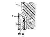
図2,図3,図11〜図13において,帽体2の一側,望ましくは左側のブラケット板7の外側面には,前記ビス9を囲繞する支筒50が一体に突設される。この支筒50は,その直径線に沿った切欠き51,51により上下一対の支筒壁50a,50bに分割されている。支筒50の外周には,合成樹脂製の制御レバー52の環状ボス52aが回転可能に嵌合され,前記切欠き51,51に係合しながら環状ボス52aの上面に対向する一対の鍔部53a,53bを有する押さえ板53が前記ビス9によりブラケット板7と共に帽体2に固着される。したがって環状ボス52aは,押さえ板53により支筒50との嵌合状態が保持される。上記ビス9及び環状ボス52aは,全閉位置を占めるシールド板4により覆われるようになっている。
【0034】
制御レバー52は,環状ボス52aの下端に連設されてシールド板4の下端縁に対向するカム52bと,このカム52bからシールド板4の外側方且つ支筒50の後方に延びる撮み52cとを備えており,中立位置N(図13参照)を中心にして,前方に向かって微開位置A(図14参照),後方に向かってロック位置B(図15参照)へと撮み52cにより回動操作されるようになっている。
【0035】
上記3位置N,A,Bに制御レバー52を保持し得るよう,上部の支筒壁50aの外周面に上記3位置N,A,Bに対応して周方向に等間隔に並ぶ3個のクリックノッチ54…が形成される一方,これらクリックノッチ54…に選択的に係合し得るクリック突起55が環状ボス52aの内周面に形成される。
【0036】
また環状ボス52aには,これに半径方向の弾性を付与すべく1個の合口56が設けられ,クリック突起55がクリックノッチ54…に弾性的に係合し得るようになっている。
【0037】
さらに,環状ボス52aの内周面には,押さえ板53の一方の鍔部53aと係合する円弧状凹部57が形成され,この凹部57の周方向両端壁に上記鍔部53aが当接することにより,制御レバー52のロック位置Bから微開位置Aまでの最大回転角度が規制されるようになっている。
【0038】
制御レバー52は,これを中立位置Nにセットするときはシールド板4の全閉を許容し,制御レバー52を中立位置Nから微開位置Aへ回動すると,カム52bがシールド板4の下端縁を僅かに押し上げてシールド板4に微小開度を付与するようになっている。このときのシールド板4の微小開度は,前記クリックストップ機構39により規制されるシールド板4の単位開度より小さく設定される。
【0039】
さて,制御レバー52とシールド板4との間には,制御レバー52をロック位置Bにセットしたとき,シールド板4を全閉位置に拘束するロック手段60が設けられる。このロック手段60は,シールド板4の内側面に形成されて,前記クリックストップ機構39の歯形壁38と一体化された当接突起61と,環状ボス52aの後部に突設されるロック爪52dとから構成され,シールド板4が全閉状態のとき,制御レバー52をロック位置Bまで回動すると,ロック爪52dが当接突起61の前面に当接して,シールド板4を全閉位置に拘束するようになっている。
【0040】
またロック爪52dの上部には斜面62が形成され,制御レバー52が先にロック位置Bにセットした後,シールド板4を全閉させると,当接突起61が上記斜面62を押圧して制御レバー52を中立位置Nに戻すようになっている。
【0041】
次に,この実施例の作用について説明する。
【0042】
制御レバー52を中立位置Nにセットした状態では,図13に示すように,そのロック爪52dがシールド板4の当接突起61の回動経路外に退去しているので,シールド板4の下端縁に指を掛けて,ロック爪52dに干渉されることなくシールド板4を全閉位置から所望の開度に回動することができる。
【0043】
シールド板4が全閉位置にあるとき,図14に示すように,制御レバー52を中立位置Nから微開位置Aへ回動すると,カム52bがシールド板4を,クリックストップ機構39により規制されるシールド板4の単位開度より小さい微小開度に開くことができ,これによりシールド板4の下方から窓3に走行風が少量供給され,帽体2内の換気を適度に図ることができる。
【0044】
図15に示すように,シールド板4を全閉状態にしてから,制御レバー52をロック位置Bにセットすると,そのロック爪52dがシールド板4内面の当接突起61の前面に当接してシールド板4の開放を阻止するので,強風や振動を受けても,シールド板4の全閉位置からの妄動を防ぐことができる。
【0045】
しかも制御レバー52によるシールド板4の拘束及び拘束解除に際しては,当接突起61及びロック爪52dは,単に相互に当接,離間するのみで,擦れ合うことがないから,長期間の使用によるも摩耗することがなく,したがって常にシールド板4の拘束及び拘束解除を的確に行うことができる。
【0046】
その上,当接突起61は,クリックストップ機構39の歯形壁38と一体にシールド板4内面に形成されるので,比較的大きい歯形壁38により効果的に補強されることになり,シールド板4の全閉位置での拘束強度を高めることができる。
【0047】
シールド板4が開放状態にあるとき,先に制御レバー52をロック位置Bにセットし,その後でシールド板4を全閉位置まで回動すると,当接突起61がロック爪52d上部の斜面62を押圧して制御レバー52を中立位置Nに戻すことができるので,ロック爪52dに邪魔されることなくシールド板4を確実に全閉状態にすることができる。その後,改めて制御レバー52をロック位置Bにセットすれば,シールド板4を全閉位置に拘束することになることは,前述の通りである。
【0048】
上記実施例においては,本発明の要旨を逸脱することなく,種々の設計変更が可能である。。
【0049】
【発明の効果】
以上のように本発明の第1の特徴によれば,帽体とそれに枢支されるシールド板との間に設けられて,シールド板を全閉位置,全開位置及び複数の中間開度位置に保持し得るクリックストップ機構と,帽体に軸支されて,帽体の全閉を許容する中立位置及び,全閉位置のシールド板を押し上げて微小開度に開く微開位置の間を回動し得る制御レバーとを備える,ヘルメットのシールド板制御装置において,前記制御レバーに,それを中立位置から微開位置と反対方向へ回動して得るロック位置を与え,シールド板の内側面に当接突起を形成する一方,前記制御レバーに,シールド板が全閉位置にあるとき該制御レバーを前記ロック位置に回動すると,前記当接突起の前面に当接してシールド板の開放を阻止するロック爪を形成したので,シールド板を全閉状態にしてから,制御レバーをロック位置にセットすると,そのロック爪がシールド板内面の当接突起の前面に当接してシールド板を全閉位置に拘束することができる。しかも制御レバーによるシールド板の拘束及び拘束解除に際しては,当接突起及びロック爪は,単に相互に当接,離間するのみで,擦れ合うことがないから,長期間の使用によるも摩耗することがなく,したがって常にシールド板の拘束及び拘束解除を的確に行うことができる。
【0050】
また本発明の第2の特徴によれば,第1の特徴に加えて,前記ロック爪には,前記制御レバーがロック位置にあるとき,シールド板を開放位置から全閉位置まで回動すると,前記当接突起に押圧されて該制御レバーを中立位置に回動させる斜面を形成したので,先に制御レバーをロック位置にセットし,次いでシールド板を全閉位置まで回動する場合でも,当接突起がロック爪上部の斜面を押圧して制御レバーを中立位置に戻すことができる,ロック爪に邪魔されることなくシールド板を確実に全閉状態にし得る。
【0051】
さらに本発明の第3の特徴によれば,第1又は第2の特徴に加えて,前記当接突起を,前記クリックストップ機構の,シールド板内面に形成されたクリック歯を有する歯形壁に一体に連設したので,当接突起は,比較的大きい歯形壁により効果的に補強されることになり,シールド板の全閉位置での拘束強度を高めることができる。
【図面の簡単な説明】
【図1】本発明のシールド板制御装置を備えたヘルメットの側面図。
【図2】図1の一部破断拡大側面図。
【図3】同ヘルメットの要部分解斜視図。
【図4】図2の4−4線断面図。
【図5】図2の5−5線断面図。
【図6】同ヘルメットの,シールド板全開状態での要部拡大側面図。
【図7】図6の7−7線断面図。
【図8】図6の8−8線断面図。
【図9】シールド板の取外し方を説明する同ヘルメットの要部拡大側面図。
【図10】図9の10−10線断面図。
【図11】図2の11−11線断面図。
【図12】図2の12−12線断面図。
【図13】図12の13−13線断面図で制御レバーの非作動状態を示す。
【図14】制御レバーによるシールド板の微開状態を示す図13との対応図。
【図15】制御レバーによるシールド板の全閉ロック状態を示す図13との対応図。
【符号の説明】
1・・・・・ヘルメット
2・・・・・帽体
4・・・・・シールド板
37・・・・クリック歯
38・・・・歯形壁
39・・・・クリックストップ機構
52・・・・制御レバー
52a・・・環状ボス
52b・・・カム
52d・・・ロック爪
61・・・・当接突起
60・・・・ロック手段
A・・・・・制御レバーの微開位置
B・・・・・制御レバーの中立位置
N・・・・・制御レバーのロック位置[0001]
[Industrial application fields]
The present invention provides a click stop mechanism that is provided between a cap body and a shield plate pivotally supported by the cap body and can hold the shield plate in a fully closed position, a fully open position, and a plurality of intermediate opening positions, and a cap body. A neutral position that allows the cap body to be fully closed, and a control lever that can be rotated between a slightly open position that pushes up the shield plate in the fully closed position and opens it to a small opening degree. The present invention relates to a shield plate control device for a helmet worn by an occupant, and more particularly to an improvement of a bag equipped with a lock means that can restrain a shield plate to a fully closed position.
[0002]
[Prior art]
Among such shield plate control devices for helmets, a device having a locking means capable of restraining the shield plate to the fully closed position has already been known as disclosed in, for example, Japanese Patent Laid-Open No. 5-214604.
[0003]
[Problems to be solved by the invention]
By the way, as disclosed in the above publication, the conventional device forms a locking hole on the inner surface of the shield plate, and engages with the locking hole to lock the shield plate in the fully closed position. Is fixed to the cap body, and when the control lever is rotated from the neutral position to the slightly opened position, the shield plate is scooped up from the inside by the cam formed on the lever, and the locking hole of the locking shield plate is formed. In such cases, each time the control lever is rotated from the neutral position to the slightly open position in order to disengage the locking hole of the locking shield plate from the locking pin of the cap body, Since the cam rubs the inner surface of the shield plate strongly, if the rubbed part wears during long-term use, it may be difficult to remove the locking hole from the lock pin.
[0004]
The present invention has been made in view of such circumstances, and by using a control lever, the shield plate can be restrained and released in the fully closed position accurately for a long period of time without having a strongly rubbing portion. An object of the present invention is to provide a helmet shield plate control device.
[0005]
[Means for Solving the Problems]
In order to achieve the above object, the present invention is provided between a cap body and a shield plate pivotally supported by the cap body, and can hold the shield plate in a fully closed position, a fully open position, and a plurality of intermediate opening positions. A click stop mechanism and a control that can be pivoted between a neutral position that is pivotally supported by the cap body and allows the cap body to be fully closed, and a fine opening position that pushes up the shield plate in the fully closed position and opens it to a small opening. In a shield plate control device for a helmet comprising a lever, the control lever is provided with a lock position obtained by rotating it from the neutral position in the direction opposite to the slightly open position, and a contact protrusion is provided on the inner surface of the shield plate. On the other hand, when the shield plate is in the fully closed position, when the control lever is rotated to the lock position, the control lever is provided with a lock claw that abuts against the front surface of the abutment protrusion and prevents the shield plate from being opened. The first special feature To.
[0006]
According to the first feature, when the control lever is set to the locked position after the shield plate is fully closed, the lock claw comes into contact with the front surface of the contact protrusion on the inner surface of the shield plate to fully close the shield plate. Can be constrained to a position. In addition, when the shield plate is restrained and released by the control lever, the abutment protrusion and the lock claw are merely abutted and separated from each other and do not rub against each other, so that they do not wear even after long-term use. Thus, the shield plate can always be properly restrained and released.
[0007]
According to the present invention, in addition to the first feature, when the shield lever is rotated from the open position to the fully closed position when the control lever is in the lock position, the lock claw is pressed by the contact protrusion. The second feature is that a slope for rotating the control lever to the neutral position is formed.
[0008]
According to the second feature, even when the control lever is first set to the lock position and then the shield plate is rotated to the fully closed position, the contact protrusion presses the slope on the upper side of the lock claw so that the control lever is Since it can return to the neutral position, the shield plate can be surely fully closed without being obstructed by the locking claw.
[0009]
Furthermore, in addition to the first or the second feature, the present invention is characterized in that the contact protrusion is integrally connected to a tooth profile wall having click teeth formed on an inner surface of the shield plate of the click stop mechanism. Three features.
[0010]
According to the third feature, the contact protrusion is effectively reinforced by the relatively large tooth profile wall, and the restraining strength at the fully closed position of the shield plate can be increased.
[0011]
DETAILED DESCRIPTION OF THE INVENTION
Embodiments of the present invention will be described below based on one embodiment of the present invention shown in the accompanying drawings.
[0012]
1 is a side view of a helmet provided with a shield plate control device of the present invention, FIG. 2 is a partially broken enlarged side view of FIG. 1, FIG. 3 is an exploded perspective view of the main part of the helmet, and FIG. 4 is a sectional view taken along line 5-5, FIG. 5 is a sectional view taken along line 5-5 in FIG. 2, FIG. 6 is an enlarged side view of the main part of the helmet in a fully opened state, and FIG. 8 is a cross-sectional view taken along line 8-8 in FIG. 6, FIG. 9 is an enlarged side view of the main part of the helmet for explaining how to remove the shield plate, FIG. 10 is a cross-sectional view taken along line 10-10 in FIG. 2 is a sectional view taken along line 11-11 in FIG. 2, FIG. 12 is a sectional view taken along line 12-12 in FIG. 2, FIG. 13 is a sectional view taken along line 13-13 in FIG. FIG. 15 is a view corresponding to FIG. 13 showing the slightly opened state of the shield plate by FIG. It is the corresponding view.
[0013]
First, in FIG. 1,
[0014]
As shown in FIGS. 2 and 3, shallow
[0015]
As shown in FIGS. 2 to 5, a
[0016]
Further, the
[0017]
A
[0018]
The
[0019]
A ring-shaped
[0020]
The
[0021]
A lock spring 28 (see FIG. 7) that biases the
[0022]
Further, in order to prevent the
[0023]
Further, both ends of the
[0024]
On the other hand, on the inner surfaces of the left and right end portions of the
[0025]
A locking
[0026]
Further, the
[0027]
The fully open position of the
[0028]
To attach the
[0029]
Therefore, first, the end of the
[0030]
When the
[0031]
On the other hand, in the
[0032]
In this case, in particular, the
[0033]
2, 3, and 11 to 13, a
[0034]
The
[0035]
In order to be able to hold the
[0036]
Further, the
[0037]
Further, an
[0038]
When the
[0039]
Now, between the
[0040]
A
[0041]
Next, the operation of this embodiment will be described.
[0042]
In the state where the
[0043]
When the
[0044]
As shown in FIG. 15, when the
[0045]
Moreover, when the
[0046]
In addition, since the
[0047]
When the
[0048]
In the embodiment described above, various design changes can be made without departing from the gist of the present invention. .
[0049]
【The invention's effect】
As described above, according to the first feature of the present invention, the shield plate is provided between the cap body and the shield plate pivotally supported by the cap body so that the shield plate is in the fully closed position, the fully open position, and the plurality of intermediate opening positions. Rotating between a click stop mechanism that can be held, a neutral position that is pivotally supported by the cap body and allows the cap body to be fully closed, and a micro-open position that opens the shield plate in the fully closed position to open a small opening In the helmet shield plate control device, the lock lever is provided with a lock position obtained by rotating the control lever from the neutral position in the direction opposite to the slight opening position, and is applied to the inner surface of the shield plate. While the contact protrusion is formed, the control lever is brought into contact with the front face of the contact protrusion to prevent the shield plate from being opened when the control lever is rotated to the lock position when the shield plate is in the fully closed position. Because the lock claw was formed, The de plate after fully closed, by setting the control lever to the lock position can be constrained in the fully closed position the shield plate the lock pawl is brought into contact with the front surface of the contact protrusion of the shield plate inner surface. In addition, when the shield plate is restrained and released by the control lever, the abutment protrusion and the lock claw are merely abutted and separated from each other and do not rub against each other, so that they do not wear even after long-term use. Thus, the shield plate can always be properly restrained and released.
[0050]
Further, according to the second feature of the present invention, in addition to the first feature, when the control lever is in the lock position, the lock claw rotates the shield plate from the open position to the fully closed position. Even when the control lever is first set to the lock position and then the shield plate is rotated to the fully closed position, the slope is formed by pressing the contact protrusion to turn the control lever to the neutral position. The contact projection can press the slope on the upper part of the lock claw to return the control lever to the neutral position. The shield plate can be surely fully closed without being obstructed by the lock claw.
[0051]
Furthermore, according to the third feature of the present invention, in addition to the first or second feature, the contact protrusion is integrated with a tooth profile wall having click teeth formed on the inner surface of the shield plate of the click stop mechanism. Therefore, the contact protrusion is effectively reinforced by a relatively large tooth profile wall, and the restraint strength at the fully closed position of the shield plate can be increased.
[Brief description of the drawings]
FIG. 1 is a side view of a helmet equipped with a shield plate control device of the present invention.
2 is a partially cutaway enlarged side view of FIG. 1. FIG.
FIG. 3 is an exploded perspective view of a main part of the helmet.
4 is a cross-sectional view taken along line 4-4 of FIG.
5 is a cross-sectional view taken along line 5-5 of FIG.
FIG. 6 is an enlarged side view of the main part of the helmet when the shield plate is fully opened.
7 is a cross-sectional view taken along line 7-7 in FIG.
8 is a cross-sectional view taken along line 8-8 in FIG.
FIG. 9 is an enlarged side view of the main part of the helmet for explaining how to remove the shield plate.
10 is a sectional view taken along line 10-10 in FIG. 9;
11 is a sectional view taken along line 11-11 in FIG.
12 is a sectional view taken along line 12-12 of FIG. 2;
13 is a cross-sectional view taken along line 13-13 in FIG. 12, showing a non-actuated state of the control lever.
14 is a view corresponding to FIG. 13 showing a slightly opened state of the shield plate by the control lever.
FIG. 15 is a view corresponding to FIG. 13 showing a fully closed lock state of the shield plate by the control lever.
[Explanation of symbols]
DESCRIPTION OF
Claims (3)
Translated fromJapanese前記制御レバー(52)に,それを中立位置(N)から微開位置(A)と反対方向へ回動して得るロック位置(B)を与え,シールド板(4)の内側面に当接突起(61)を形成する一方,前記制御レバー(52)に,シールド板(4)が全閉位置にあるとき該制御レバー(52)を前記ロック位置(B)に回動すると,前記当接突起(61)の前面に当接してシールド板(4)の開放を阻止するロック爪(52d)を形成したことを特徴とする,ヘルメットのシールド板制御装置。A click stop mechanism provided between the cap body (2) and the shield plate (4) pivotally supported by the cap body (2) and capable of holding the shield plate (4) in the fully closed position, the fully open position, and a plurality of intermediate opening positions. (39) and the neutral position (N) that is pivotally supported by the cap body (2) and allows the cap body (2) to be fully closed, and the shield plate (4) in the fully closed position is pushed up to a small opening degree. A shield plate control device for a helmet, comprising a control lever (52) capable of rotating between an open micro-open position (A),
The control lever (52) is given a lock position (B) obtained by rotating it from the neutral position (N) in the direction opposite to the slightly open position (A), and abuts against the inner surface of the shield plate (4). When the control lever (52) is rotated to the lock position (B) when the shield plate (4) is in the fully closed position while the protrusion (61) is formed, A shield plate control device for a helmet, characterized in that a lock claw (52d) is formed in contact with the front surface of the projection (61) to prevent the shield plate (4) from being opened.
前記当接突起(61)を,前記クリックストップ機構(39)の,シールド板(4)内面に形成されたクリック歯(37)を有する歯形壁(38)に一体に連設したことを特徴とする,ヘルメットのシールド板制御装置。The helmet shield plate control device according to claim 1 or 2,
The contact protrusion (61) is integrally connected to a tooth profile wall (38) having a click tooth (37) formed on the inner surface of the shield plate (4) of the click stop mechanism (39). The helmet shield plate control device.
Priority Applications (4)
| Application Number | Priority Date | Filing Date | Title |
|---|---|---|---|
| JP2001149630AJP4656756B2 (en) | 2001-05-18 | 2001-05-18 | Helmet shield plate control device |
| US10/146,664US6654969B2 (en) | 2001-05-18 | 2002-05-15 | System for controlling shield plate for helmet |
| EP02011064AEP1260148B1 (en) | 2001-05-18 | 2002-05-17 | System for controlling shield plate for helmet |
| DE60225868TDE60225868T2 (en) | 2001-05-18 | 2002-05-17 | Actuator for a helmet visor |
Applications Claiming Priority (1)
| Application Number | Priority Date | Filing Date | Title |
|---|---|---|---|
| JP2001149630AJP4656756B2 (en) | 2001-05-18 | 2001-05-18 | Helmet shield plate control device |
Publications (2)
| Publication Number | Publication Date |
|---|---|
| JP2002339142A JP2002339142A (en) | 2002-11-27 |
| JP4656756B2true JP4656756B2 (en) | 2011-03-23 |
Family
ID=18994769
Family Applications (1)
| Application Number | Title | Priority Date | Filing Date |
|---|---|---|---|
| JP2001149630AExpired - Fee RelatedJP4656756B2 (en) | 2001-05-18 | 2001-05-18 | Helmet shield plate control device |
Country Status (4)
| Country | Link |
|---|---|
| US (1) | US6654969B2 (en) |
| EP (1) | EP1260148B1 (en) |
| JP (1) | JP4656756B2 (en) |
| DE (1) | DE60225868T2 (en) |
Families Citing this family (28)
| Publication number | Priority date | Publication date | Assignee | Title |
|---|---|---|---|---|
| EP1397969B1 (en)* | 2002-09-12 | 2006-09-06 | OPTICOS S.r.l. | Device for mounting the visor onto the cap of a helmet |
| US6732380B1 (en)* | 2003-02-27 | 2004-05-11 | Long Huei Helmet Co. | Fixing device for the windshield of a safety helmet |
| US7065798B2 (en)* | 2004-11-17 | 2006-06-27 | Kin Yong Lung Industrial Co., Ltd. | Helmet shield provided with positioning and adjusting device |
| KR100568946B1 (en)* | 2004-11-25 | 2006-04-10 | 주식회사 홍진에이치제이씨 | Shield coupling device for helmet |
| TWM273977U (en)* | 2005-04-13 | 2005-09-01 | Bing-Jang Ye | Union structure of helmet lens and helmet body |
| KR100659171B1 (en)* | 2005-12-15 | 2006-12-19 | 주식회사 홍진에이치제이씨 | Opening and closing mechanism of the jaw guard for helmet |
| JP4895647B2 (en)* | 2006-03-17 | 2012-03-14 | 株式会社Shoei | helmet |
| US8069499B2 (en)* | 2006-05-15 | 2011-12-06 | Shoei Co., Ltd. | Helmet shield attaching mechanism, and helmet attached with the same |
| JP4215797B2 (en)* | 2006-12-14 | 2009-01-28 | 株式会社アライヘルメット | Shield lock mechanism in helmet |
| US8161576B2 (en) | 2007-02-01 | 2012-04-24 | Sellstrom Manufacturing Company | Protective headgear assembly |
| JP4976153B2 (en)* | 2007-02-06 | 2012-07-18 | 株式会社Shoei | How to adjust the helmet size |
| US7987525B2 (en)* | 2007-04-13 | 2011-08-02 | Klim | Helmet |
| JP5041906B2 (en)* | 2007-08-07 | 2012-10-03 | 株式会社Shoei | helmet |
| KR100951343B1 (en)* | 2008-01-21 | 2010-04-08 | 주식회사 홍진에이치제이씨 | Helmet |
| US8214920B1 (en) | 2008-02-18 | 2012-07-10 | Sperian Eye & Face Protection, Inc. | Hard hat adapter for a welding helmet |
| US8166576B2 (en)* | 2008-05-21 | 2012-05-01 | Katoh Electrical Machinery Co., Ltd. | Opening/closing device and helmet having the same |
| DE102008049023B4 (en)* | 2008-09-25 | 2014-09-25 | Long Huei Helmet Co. | Safety helmet visor adjustment |
| ITVR20090070A1 (en)* | 2009-05-19 | 2010-11-20 | Agv Spa | HANDLING DEVICE FOR A HELMET TO MOVE A FIRST ELEMENT OF THE HELMET COMPARED TO A SECOND HELMET ELEMENT |
| KR101150796B1 (en)* | 2009-07-29 | 2012-06-13 | 주식회사 홍진에이치제이씨 | Helmet |
| ITVR20120022A1 (en)* | 2012-02-20 | 2013-08-21 | Agv Spa | HANDLING DEVICE FOR A HELMET TO MOVE A FIRST ELEMENT OF THE HELMET COMPARED TO A SECOND HELMET ELEMENT. |
| JP6148538B2 (en)* | 2013-06-03 | 2017-06-14 | 株式会社Shoei | Helmet shield mounting mechanism |
| JP6259640B2 (en)* | 2013-10-31 | 2018-01-10 | 株式会社アライヘルメット | Shield for helmet |
| US10154704B1 (en)* | 2015-04-17 | 2018-12-18 | Desmark Industries, Inc. | Helmet slide assembly |
| JP7168480B2 (en)* | 2019-02-08 | 2022-11-09 | 株式会社Shoei | Visor locking mechanism and helmet |
| CN109875177B (en)* | 2019-03-04 | 2024-02-13 | 江门市鹏程头盔有限公司 | A gear-constrained helmet with variable jaw protection structure |
| JP6917487B2 (en) | 2020-01-29 | 2021-08-11 | 株式会社Shoei | Shield lock mechanism and helmet |
| US11583026B2 (en)* | 2021-02-09 | 2023-02-21 | LIFT Airborne Technologies LLC | Automatic visor locking system |
| CA3189539A1 (en)* | 2022-02-17 | 2023-08-17 | Kimpex Inc. | Visor assembly with unique plate |
Family Cites Families (11)
| Publication number | Priority date | Publication date | Assignee | Title |
|---|---|---|---|---|
| JPS63309612A (en)* | 1987-06-09 | 1988-12-16 | 新井 理夫 | Shield mount structure in helmet |
| JPH02234906A (en)* | 1989-03-08 | 1990-09-18 | Dainippon Ink & Chem Inc | Helmet |
| JPH04100910A (en)* | 1990-08-20 | 1992-04-02 | Shoei Kako Kk | Structure for installing shielding plate of helmet |
| JPH0621369B2 (en)* | 1991-02-04 | 1994-03-23 | 昭栄化工株式会社 | Shield plate opening / closing control device for helmet |
| JPH077285Y2 (en)* | 1991-02-19 | 1995-02-22 | 昭栄化工株式会社 | Helmet shield device |
| JPH05214604A (en)* | 1992-01-31 | 1993-08-24 | Shoei Kako Kk | Shield control device for helmet |
| JPH0562529U (en)* | 1992-02-03 | 1993-08-20 | 昭栄化工株式会社 | Shield plate support structure in helmet |
| JPH086202B2 (en)* | 1993-06-18 | 1996-01-24 | 昭栄化工株式会社 | Shield plate mounting structure for helmet |
| JPH08232111A (en)* | 1995-02-27 | 1996-09-10 | Shoei Kako Kk | Helmet shield plate support device |
| EP0783842B1 (en)* | 1995-12-22 | 2000-05-24 | E.D.C. Sa | Device for locking in closed position the visor of helmets for motorcyclists and the like |
| JPH10110320A (en)* | 1996-09-30 | 1998-04-28 | Koshin Crown:Kk | Device for attaching shield plate of helmet |
- 2001
- 2001-05-18JPJP2001149630Apatent/JP4656756B2/ennot_activeExpired - Fee Related
- 2002
- 2002-05-15USUS10/146,664patent/US6654969B2/ennot_activeExpired - Lifetime
- 2002-05-17DEDE60225868Tpatent/DE60225868T2/ennot_activeExpired - Lifetime
- 2002-05-17EPEP02011064Apatent/EP1260148B1/ennot_activeExpired - Lifetime
Also Published As
| Publication number | Publication date |
|---|---|
| US6654969B2 (en) | 2003-12-02 |
| EP1260148A2 (en) | 2002-11-27 |
| US20020189005A1 (en) | 2002-12-19 |
| DE60225868T2 (en) | 2009-04-09 |
| JP2002339142A (en) | 2002-11-27 |
| DE60225868D1 (en) | 2008-05-15 |
| EP1260148A3 (en) | 2005-08-24 |
| EP1260148B1 (en) | 2008-04-02 |
Similar Documents
| Publication | Publication Date | Title |
|---|---|---|
| JP4656756B2 (en) | Helmet shield plate control device | |
| EP0629357B1 (en) | Shield plate mounting structure in helmet | |
| JPH0621369B2 (en) | Shield plate opening / closing control device for helmet | |
| US4907299A (en) | Shield mounting assembly for a safety helmet | |
| US6711753B2 (en) | Shield fixing structure in helmet | |
| US20060117467A1 (en) | Shield mounting device for helmet | |
| JPH0662150U (en) | Lock handle device for drawer revolving door | |
| EP0105536B1 (en) | Bicycle pedal with foot holder | |
| GB2063988A (en) | Combination lock | |
| JPH0953352A (en) | Ignition switch | |
| JP3404250B2 (en) | Ignition switch | |
| JPH072432U (en) | Click-stop mechanism for helmet shield plate | |
| GB2087222A (en) | Device for adjusting the opening of the visors in crash helmets for motorcyclists and the like | |
| KR960001132B1 (en) | Rotation limit mechanism of rotary drive shaft for sliding roof of automobile | |
| JPS60135338A (en) | Reclining device of seat | |
| GB2404233A (en) | Adjustment mechanism | |
| GB2087220A (en) | Device for adjusting the opening of the visors in crash helmets for motorcyclists and the like | |
| JPH0723777Y2 (en) | Aperture ring lock mechanism for lens barrel | |
| JP2563244Y2 (en) | Single lever hot water mixer tap with safety button | |
| JP2668519B2 (en) | Horseshoe | |
| JPH0415896Y2 (en) | ||
| US20010026407A1 (en) | Barrier opening and closing apparatus | |
| KR100415053B1 (en) | Door lock device | |
| JP3395888B2 (en) | Helmet shield mounting structure | |
| JP2001103884A5 (en) |
Legal Events
| Date | Code | Title | Description |
|---|---|---|---|
| A621 | Written request for application examination | Free format text:JAPANESE INTERMEDIATE CODE: A621 Effective date:20080324 | |
| A977 | Report on retrieval | Free format text:JAPANESE INTERMEDIATE CODE: A971007 Effective date:20100127 | |
| TRDD | Decision of grant or rejection written | ||
| A01 | Written decision to grant a patent or to grant a registration (utility model) | Free format text:JAPANESE INTERMEDIATE CODE: A01 Effective date:20101201 | |
| A01 | Written decision to grant a patent or to grant a registration (utility model) | Free format text:JAPANESE INTERMEDIATE CODE: A01 | |
| A61 | First payment of annual fees (during grant procedure) | Free format text:JAPANESE INTERMEDIATE CODE: A61 Effective date:20101221 | |
| FPAY | Renewal fee payment (event date is renewal date of database) | Free format text:PAYMENT UNTIL: 20140107 Year of fee payment:3 | |
| R150 | Certificate of patent or registration of utility model | Free format text:JAPANESE INTERMEDIATE CODE: R150 | |
| R250 | Receipt of annual fees | Free format text:JAPANESE INTERMEDIATE CODE: R250 | |
| LAPS | Cancellation because of no payment of annual fees |