JP4656730B2 - Cassette for vacuum and steam sterilizer - Google Patents
Cassette for vacuum and steam sterilizerDownload PDFInfo
- Publication number
- JP4656730B2 JP4656730B2JP2000609113AJP2000609113AJP4656730B2JP 4656730 B2JP4656730 B2JP 4656730B2JP 2000609113 AJP2000609113 AJP 2000609113AJP 2000609113 AJP2000609113 AJP 2000609113AJP 4656730 B2JP4656730 B2JP 4656730B2
- Authority
- JP
- Japan
- Prior art keywords
- cassette
- seal
- valve
- tray
- lid
- Prior art date
- Legal status (The legal status is an assumption and is not a legal conclusion. Google has not performed a legal analysis and makes no representation as to the accuracy of the status listed.)
- Expired - Lifetime
Links
Images


Classifications
- A—HUMAN NECESSITIES
- A61—MEDICAL OR VETERINARY SCIENCE; HYGIENE
- A61L—METHODS OR APPARATUS FOR STERILISING MATERIALS OR OBJECTS IN GENERAL; DISINFECTION, STERILISATION OR DEODORISATION OF AIR; CHEMICAL ASPECTS OF BANDAGES, DRESSINGS, ABSORBENT PADS OR SURGICAL ARTICLES; MATERIALS FOR BANDAGES, DRESSINGS, ABSORBENT PADS OR SURGICAL ARTICLES
- A61L2/00—Methods or apparatus for disinfecting or sterilising materials or objects other than foodstuffs or contact lenses; Accessories therefor
- A61L2/02—Methods or apparatus for disinfecting or sterilising materials or objects other than foodstuffs or contact lenses; Accessories therefor using physical phenomena
- A61L2/04—Heat
- A61L2/06—Hot gas
- A61L2/07—Steam
- A—HUMAN NECESSITIES
- A61—MEDICAL OR VETERINARY SCIENCE; HYGIENE
- A61L—METHODS OR APPARATUS FOR STERILISING MATERIALS OR OBJECTS IN GENERAL; DISINFECTION, STERILISATION OR DEODORISATION OF AIR; CHEMICAL ASPECTS OF BANDAGES, DRESSINGS, ABSORBENT PADS OR SURGICAL ARTICLES; MATERIALS FOR BANDAGES, DRESSINGS, ABSORBENT PADS OR SURGICAL ARTICLES
- A61L2/00—Methods or apparatus for disinfecting or sterilising materials or objects other than foodstuffs or contact lenses; Accessories therefor
- A61L2/02—Methods or apparatus for disinfecting or sterilising materials or objects other than foodstuffs or contact lenses; Accessories therefor using physical phenomena
- A61L2/08—Radiation
- A—HUMAN NECESSITIES
- A61—MEDICAL OR VETERINARY SCIENCE; HYGIENE
- A61L—METHODS OR APPARATUS FOR STERILISING MATERIALS OR OBJECTS IN GENERAL; DISINFECTION, STERILISATION OR DEODORISATION OF AIR; CHEMICAL ASPECTS OF BANDAGES, DRESSINGS, ABSORBENT PADS OR SURGICAL ARTICLES; MATERIALS FOR BANDAGES, DRESSINGS, ABSORBENT PADS OR SURGICAL ARTICLES
- A61L2/00—Methods or apparatus for disinfecting or sterilising materials or objects other than foodstuffs or contact lenses; Accessories therefor
- A61L2/24—Apparatus using programmed or automatic operation
- A—HUMAN NECESSITIES
- A61—MEDICAL OR VETERINARY SCIENCE; HYGIENE
- A61L—METHODS OR APPARATUS FOR STERILISING MATERIALS OR OBJECTS IN GENERAL; DISINFECTION, STERILISATION OR DEODORISATION OF AIR; CHEMICAL ASPECTS OF BANDAGES, DRESSINGS, ABSORBENT PADS OR SURGICAL ARTICLES; MATERIALS FOR BANDAGES, DRESSINGS, ABSORBENT PADS OR SURGICAL ARTICLES
- A61L2/00—Methods or apparatus for disinfecting or sterilising materials or objects other than foodstuffs or contact lenses; Accessories therefor
- A61L2/26—Accessories or devices or components used for biocidal treatment
- A—HUMAN NECESSITIES
- A61—MEDICAL OR VETERINARY SCIENCE; HYGIENE
- A61L—METHODS OR APPARATUS FOR STERILISING MATERIALS OR OBJECTS IN GENERAL; DISINFECTION, STERILISATION OR DEODORISATION OF AIR; CHEMICAL ASPECTS OF BANDAGES, DRESSINGS, ABSORBENT PADS OR SURGICAL ARTICLES; MATERIALS FOR BANDAGES, DRESSINGS, ABSORBENT PADS OR SURGICAL ARTICLES
- A61L2202/00—Aspects relating to methods or apparatus for disinfecting or sterilising materials or objects
- A61L2202/10—Apparatus features
- A61L2202/12—Apparatus for isolating biocidal substances from the environment
- A61L2202/122—Chambers for sterilisation
- A—HUMAN NECESSITIES
- A61—MEDICAL OR VETERINARY SCIENCE; HYGIENE
- A61L—METHODS OR APPARATUS FOR STERILISING MATERIALS OR OBJECTS IN GENERAL; DISINFECTION, STERILISATION OR DEODORISATION OF AIR; CHEMICAL ASPECTS OF BANDAGES, DRESSINGS, ABSORBENT PADS OR SURGICAL ARTICLES; MATERIALS FOR BANDAGES, DRESSINGS, ABSORBENT PADS OR SURGICAL ARTICLES
- A61L2202/00—Aspects relating to methods or apparatus for disinfecting or sterilising materials or objects
- A61L2202/10—Apparatus features
- A61L2202/14—Means for controlling sterilisation processes, data processing, presentation and storage means, e.g. sensors, controllers, programs
- A—HUMAN NECESSITIES
- A61—MEDICAL OR VETERINARY SCIENCE; HYGIENE
- A61L—METHODS OR APPARATUS FOR STERILISING MATERIALS OR OBJECTS IN GENERAL; DISINFECTION, STERILISATION OR DEODORISATION OF AIR; CHEMICAL ASPECTS OF BANDAGES, DRESSINGS, ABSORBENT PADS OR SURGICAL ARTICLES; MATERIALS FOR BANDAGES, DRESSINGS, ABSORBENT PADS OR SURGICAL ARTICLES
- A61L2202/00—Aspects relating to methods or apparatus for disinfecting or sterilising materials or objects
- A61L2202/20—Targets to be treated
- A61L2202/24—Medical instruments, e.g. endoscopes, catheters, sharps
- Y—GENERAL TAGGING OF NEW TECHNOLOGICAL DEVELOPMENTS; GENERAL TAGGING OF CROSS-SECTIONAL TECHNOLOGIES SPANNING OVER SEVERAL SECTIONS OF THE IPC; TECHNICAL SUBJECTS COVERED BY FORMER USPC CROSS-REFERENCE ART COLLECTIONS [XRACs] AND DIGESTS
- Y10—TECHNICAL SUBJECTS COVERED BY FORMER USPC
- Y10T—TECHNICAL SUBJECTS COVERED BY FORMER US CLASSIFICATION
- Y10T137/00—Fluid handling
- Y10T137/9029—With coupling
Landscapes
- Health & Medical Sciences (AREA)
- Epidemiology (AREA)
- Life Sciences & Earth Sciences (AREA)
- Animal Behavior & Ethology (AREA)
- General Health & Medical Sciences (AREA)
- Public Health (AREA)
- Veterinary Medicine (AREA)
- Apparatus For Disinfection Or Sterilisation (AREA)
- Dental Tools And Instruments Or Auxiliary Dental Instruments (AREA)
Description
Translated fromJapanese【0001】
【発明の属する技術分野】
本発明は、真空および蒸気の双方を用いて器具を滅菌することができるカセット、とくに、真空および加圧の状態の間でカセットを作動可能とするシールと滅菌後、滅菌および負圧状態を維持するだけでなく、滅菌を容易とする入口および出口カップリングとを有するカセットに関する。
【0002】
【従来の技術及びその課題】
従来技術において、医療および歯科器具を滅菌する種々の方法および装置が提案されている。一般的に、これらの滅菌技術は、滅菌されるべき物品を収容するチャンバから空気をパージないし排出し、蒸気を加えて負荷を加熱して滅菌するために、蒸気および/または真空を用いる。この滅菌が実施される1の方法は、圧力釜を使用する。1の型式の圧力釜は、加圧下で所定量の沸騰水を収容する比較的大きな密封容器である。沸騰水は、容器内部から空気をパージするために使用される。他の圧力釜において、真空もパージングないし排出操作のために使用される。いずれの場合においても、不完全な空気のパージングおよび圧力釜の壁部に器具の汚染物が堆積することによって、問題が展開することがある。また、これらの圧力釜は、重い壁部および支持構造体の大きな熱容量のために、滅菌するのが本来的に遅い。
【0003】
ニューマン(Newman)に付与された米国特許第5,271,893号、第5,290,511号および第5,571,476号に開示されている装置は、従来の圧力釜の多くの欠点を解消する。これらの特許は、その記載が本明細書中において参考として採用されているが、滅菌のためにカセットを用いる蒸気をパージし、滅菌する方法および装置を開示する。カセットを使用することにより、滅菌チャンバ内部から、従来の圧力釜で必要な種類の補助搬送トレーまたはその他の滅菌後の取扱い装置への移送は必要とされない。ニューマン特許は、小規模オフィス等の環境で容易に使用することができる小さな軽量ユニットも用いる。
【0004】
ニューマン特許で教示されているカセットを使用する装置は、従来の蒸気パージング/滅菌圧力釜技術を越える大きな利点を提供するが、これらのカセットは、蒸気滅菌プロセスの一部として真空を使用することはできない。更に、これらのカセットは、滅菌済みの器具を保管する構造を有していない。
【0005】
更に、用いられる装置および方法に関係なく、より短い滅菌サイクルに対する要求が業界において絶えず増大している。
【0006】
このように、滅菌装置および方法で使用される改良された滅菌装置、とくに、より速い滅菌時間を可能とする装置が必要とされている。本発明は、真空および蒸気の双方を用いる滅菌方法および装置で使用されるカセットおよび長時間にわたって滅菌済みの器具を保管することができるカセットを提供することによりこれらの要求に応じる。
【0007】
本発明の第1の目的は、真空および加圧状態を利用する蒸気滅菌装置および方法で使用することができるカセットを提供することである。
【0008】
本発明の他の目的は、蒸気滅菌済みの器具を保管するために無菌状態を維持する構造を有するカセットを提供することである。
【0009】
本発明の更に他の目的は、滅菌方法中に、カセットが加圧および負圧状態下で作用するのを許容するシールを有するカセットを提供することである。
【0010】
本発明の他の目的および利点は、以下の種々の説明においても明らかとなるであろう。
【0011】
【課題を解決するための手段及び発明の効果】
上記目的および利点を達成するために、本発明は、ベースで支えられた器具を滅菌することができる蒸気滅菌装置のプローブに接続される入口および出口を有するトレーを備える滅菌カセットを提供する。カセットは、ベースにヒンジ止めされた蓋を有し、この蓋は蓋の周部に沿って配置されたシールを含む。蓋は、開位置と閉位置と中間位置との間を移動可能であり、蓋とシールとトレーは、蓋が閉位置および中間位置にあるときに、滅菌チャンバを形成する。
【0012】
入口および出口のそれぞれは、蒸気滅菌装置と滅菌チャンバとの間の連通を許容する第1弁を有する。第2弁が、滅菌チャンバの過剰圧を解放するためにカセットの一部として形成されている。また、第1および第2の弁は、滅菌済みの器具の保管のために滅菌チャンバをシールする。
【0013】
1の具体的構成において、シールは、蓋の周部に沿って延びる連続シールボデイを備え、第1および第2のリップがシールボデイから延び、それに枢動可能に連結される。第3のリップが、シールボデイから延び、第2のリップから離隔して、その間にチャンネルを形成する。第1および第2のリップは、チャンネルと共に、中間位置でシールを形成し、第1、第2および第2のリップは、閉位置でシールを形成する。
【0014】
出口は、チャンバ内に配置された少なくとも1の開口を有し、この少なくとも1の開口は、トレーの底部から離隔している。その一方の端部の出口にダクトを取付けることが可能であり、トレーの底部に近接して配置されたダクトの反対側端部は、器具の蒸気滅菌中、復水を回収するためのチャンネルを形成する。
【0015】
更に本発明においては、入口および出口のそれぞれは、さらに、カップリングボデイと壁部との間にシールを維持しつつ、トレーの壁部を通って可動に装荷され、滅菌装置のプローブとカップリングボデイとの間のセルフアラインメントを可能するカップリングボデイとシールとの組立体を備える。
【0016】
カセットは、カセットが除去されるときに無菌状態を維持するために独特のシールも採用する。この実施形態において、カップリングボデイの一方の端部は、滅菌チャンバの外側に配置され、第2端部は、滅菌チャンバの内側に配置される。一方の端部は、その周面にシール装置を有する。シール装置は、第1弁の開閉前に、シールが、周面とプローブの面との間に形成され、滅菌チャンバを周囲からシールするように壁部から離隔する。
【0017】
他の具体的構成において、カセットは、デュアルバルブカップリング装置を採用し、これにより、第1,第2の弁は、カップリングボデイに配置される。第1弁は、閉位置において付勢され、付勢力に抗して力がバルブフェースに加えられたときに、開くことができる。第2弁は、閉位置において付勢され、滅菌チャンバ内から力が加えられたときに、開位置に移動可能である。付勢力は、2つの弁の間に配置されたばねによって形成することができる。第1弁は、第1開口と第2弁との間を連通する孔をその中に有してもよく、これにより、滅菌チャンバが保管のために真空下にあるときに、ばね付勢力および大気圧は、第1および第2弁のそれぞれを閉位置に維持する。
【0018】
また、本発明は、滅菌カセットのための可撓性シールと蒸気および真空を用いる滅菌プロセスの一部としてカセットを使用する方法とを伴う。器具を蒸気滅菌する方法は、滅菌チャンバ内に器具を配置し、その入口および出口を蒸気滅菌装置のプローブに接続するステップを備える。器具は、加圧および負圧状態を用いる蒸気滅菌サイクルに晒される。カセットは、この後、蒸気滅菌サクル完了後に除去され、負圧状態下、カセット内で器具を保管するか、あるいは、器具は、使用のために、カセットから除去される。
【0019】
本発明は、他のカセット構造で用いることができる2重構成のデュアルバルブカップリングも含む。
【0020】
【発明の実施形態】
本発明のカセットは、医療および歯科分野で使用されるような滅菌器具の分野で優れた利点を提供する。最初に、カセットの独特のシールのために、カセットは、蒸気滅菌前にカセットから空気を除去する負圧状態と蒸気滅菌中に一般に直面する加圧状態とを用いる方法および装置で使用することができる。
【0021】
第2に、当該カセットは、滅菌済みの器具を、使用可能状態になるまで、カセット内に保管することを許容する。したがって、カセット自体は、滅菌装置としてだけでなく、滅菌された器具の保管装置としても機能する。
【0022】
第3に、カセットの構造は、滅菌装置から除去するときにカセット内側に無菌空気を維持する。
【0023】
又、本発明のカセットは、滅菌の一部として真空および蒸気の双方を使用する装置および方法で使用することができることが理解されるべきである。とくに、カセットは、トレーに対して2つの位置間を移動する蓋とシールとの組立体を有する。トレーは、カセットの内側を、滅菌プロセスの一部として真空および蒸気状態に晒すのを容易とする入口および出口カップリングを有する。
【0024】
蓋の第1位置は、閉位置であり、これにより、カセット内側は、負圧状態のとき、あるいは、滅菌状態のときに、滅菌プロセス中、あるいは、保管モードにおいて、外側からシールされる。
【0025】
蓋の第2位置は、内側が加圧され、蓋がトレーに対して持上げられたときに形成される。シールは、蓋が第1位置または閉位置にないときでも、カセット内側を外側から遮断する。
【0026】
入口および出口カップリングは、器具が滅菌された後、滅菌装置からのカセットの除去が滅菌されたカセット内側を危うくしないことを確保する構造を有する。この構造は、各カップリングに弁とシールとを用い、1組のシールがカセット外側に配置される。外側シールは、カップリングが滅菌装置の蒸気を供給する、あるいは、真空にするプローブから外されるときに、カセットの内側を遮断する。
【0027】
入口および出口カップリングは、カセット内側内の不所望な圧力の解放を可能とする圧力逃し弁も採用する。圧力逃し弁は、カップリング内の他の弁と協働して、滅菌プロセス完了後、カセット内側に負圧状態を維持する機能も果す。この状態を維持することによって、滅菌された器具は、カセット内で長時間の間保管することができる。したがって、器具は、事前に滅菌し、必要とされるまで保管することができる。
【0028】
図1は、歯科器具、医療器具等の保管のための好ましいカセットの実施形態10を示す。カセットは、2つの半片部、すなわち、以下でカセットトレー1と称される下側半片部と以下でカセット蓋3と称される上側半片部とから構成される。カセットトレー1は、底部と壁部とを有する容器であり、この壁部内に、滅菌されるべき器具が配置され、全滅菌サイクルを通して滅菌装置内で静止状態を保持する。カセット10は、その搬送位置に示されている補助ハンドル5とその休止位置に示されている前部ハンドル7とを含む。前部ハンドル7と同様な構造および構成を有し、カセット後部に配置される後部ハンドル(図示せず)も設けることができる。カセットトレーおよびカセット蓋の双方は、滅菌サイクル中、カセット収容物への熱伝達を容易とするステンレススチールまたは同様な材料から形成されるのが好ましい。他のハンドル構造を使用して、カセット10を搬送してもよいことは勿論のことである。
【0029】
本発明のカセットにおいて、以下でアーマチュアと称される枠状ないしチャンバ状の構造体を採用する滅菌装置および方法と関連して使用されたときに、組合せシステムは、歯科および医療器具の滅菌のために必要な圧力および真空の双方に耐えることができるという点にある。更に、同時に、軽量カセットは、器具の携帯性および無菌搬送/保管を提供する。滅菌システムは、カセットおよびカセットを囲むアーマチュアにより形成されるスペースの双方で真空を形成し、その結果、真空形成の全ての場合に、カセットとアーマチュアとの間の差圧が零となるために、好ましいカセットの実施形態は、真空下で機能する。カセットは、加圧中、構造的に優れたアーマチュアに、ほとんどの構造上の負荷を伝達することから、好ましいカセットの実施形態は、加圧下で機能する。したがって、滅菌サイクル中、不適当な応力が、カセット自体に作用しない。この滅菌装置は、本願出願人に係るカナダ国特許出願第2268042号に開示されている。
【0030】
カセット10は、トレー1および蓋3の双方の端部に補強部材またはバンバー6が形成されるのが好ましい。アーマチュアに接触しない領域は、カセットの上部および底部とは異なり、滅菌プロセスの加圧サイクル中、追加のサポートを有しないために、バンバー6は、これらの領域内のトレー1および蓋3に追加の構造上のサポートを提供する。バンバー6は、蓋3およびトレー1にスポット溶接されるか、あるいは、他の方法で取付けられるプレートとして図示されている。蓋およびトレーの壁部の補強リブ等のような他の形態の構造上のサポートも用いることができる。
【0031】
図2に示した上下逆転したカセット蓋3は、通常のヒンジ9を介してカセットトレー1に接続され、カセット内の圧力に応じて、カセットトレーに対して垂直方向に上下に移動することができる。ヒンジタブ11は、トレー1のフランジ12の相補的サイズのスロット8内に取付けられる(図5参照)。
【0032】
密なシールが、カセット蓋3の内側ライニングに取付けられ、エンドユーザで交換可能な両方向シールグランド13を介して、カセット蓋3とカセットトレー1との間に形成される。シール13は、蓋の周部を囲む連続した形態を有する。
【0033】
図3Aは、連続シールボデイ15と第1リップ17と第2リップ19と第3リップ21とからなる両方向シール13の断面を示す。第1リップ17と第2リップ19は、シール枢動部材23を介して、本体15に接続される。シールボデイ15は、対向壁部を有するチャンネル25内に載置され、第3リップ21は、一方の壁部27に載置される。他の壁部29は、後述のように、第1リップ17を保護する。
【0034】
カセット蓋3が図3A(開位置)に示したようにカセットトレー1から取外されたときに、第1リップ17は、その普通の位置にあり、壁部29の背部に完全に収容され、これにより、カセット蓋3を閉じるときに第1リップ17が損傷を受けるのを防止する。
【0035】
カセット蓋3を閉じるときに、図3Bに示したように、第2リップ19が、まず、カセットトレー面33に接触する。カセット蓋3がカセットトレー1に向かって下方に移動し続けるときに、第2リップ19が、シール枢動部材23を中心として上方かつ外方に回転し、第1リップ17を、カセットトレー壁35に接触して第1シール37を形成するまで、上方かつ内方に回転させる。カセット蓋3がカセットトレー1に向かって更に移動すると、第2リップ19も、カセットトレー壁35に接触して、第2シール39を形成する。最後に、第3リップ21が、カセットトレー面33に接触して、図3Cに示したように、第3の最後のシール41(閉位置)を形成する。
【0036】
図4Aに示した滅菌サイクルの加圧段階中、蒸気がカセット10内に注入され、カセット蓋3およびシール13が、滅菌装置(図示せず)のアーマチュアに位置する上部加熱板44に接触し、この加熱板によって停止するまで、上方に向けてカセットトレー1から離れる方向に移動する。第3リップ21がカセットトレーlから離れる方向に移動するときに、チャンネル43が、シールリップ21を含むシールボデイ15とトレー1の表面33と第2リップ19との間に形成される。加圧蒸気がチャンネル43に入ると、蒸気は、第2フィンガー部または加圧リップ19をカセットトレー壁35に押圧し、したがって、カセット内から外側への漏れが発生するのを防止する(中間位置)。
【0037】
加圧中のカセット蓋3の上方への移動は、ステンレススチールのカセット蓋3とアーマチュア(図示せず)に置する上部加熱板44との間とステンレススチールのカセットトレー1と下部加熱板(図示せず)との間の優れた熱接触も確保する。これは、加熱板からカセット収容物への熱伝達を容易とし、これにより、カセット収容物を滅菌温度にするのに要する時間を短縮する。
【0038】
滅菌サイクルの最後で、カセット10内の熱気は、冷却すると、その容量が減少し、これにより、図4Bに示したように、カセット内に真空を形成する。この結果、カセット蓋3は、カセットトレー1に向けて引張られる。これは、つぎに、第3リップ21をカセットトレー面33に対して圧縮し、第1リップ17をカセットトレー壁35に向けて内方に引張り、これにより、カセット10をシールし、大気がカセット10内に流入するのを防止する。
【0039】
本発明のカセットにおいては、又、蒸気滅菌プロセスの一部として、蒸気、空気等の流入および流出を可能とする入口および出口を含む。1の実施形態において、蒸気は、カセットトレー1の、以下で入口カップリング45と称されるカップリングを介してカセットに流入し、この後、カセットトレーの同一構造の、以下で出口カップリング47と称される他のカップリングを介してカセットから流出する。入口および出口カップリングは、図5に示したように、カセットトレーの後壁に装荷される。カップリング45および47は、行われている特定の滅菌サイクルに応じて、入口および出口として特徴付けられるが、双方のカップリングは、入口または出口として使用することができる。例えば、排気サイクル中、各カップリング45および47は、上述の出願人のカナダ国特許出願に記載されているように出口として使用することができる。
【0040】
図6は、滅菌システムの好ましいカップリングの実施形態と好ましい相手側プローブの実施形態とを示す。各カップリングは、カップリングフランジ51とカセットトレー1の内側後壁53との間に配置されたオーリングシール49によりカセットトレーに取付けられる。ウエーブスプリング55または同様な構造の圧縮ばねおよびねじ付ナット57が、カップリング45をトレー1に固定するために用いられる。ナット57は、カップリング45に固定されるときに、ウエーブスプリング55とオーリングシール49とを圧縮して、漏れがない取付けを形成する。同時に、この構成は、カップリング45および47のカセットトレーに対する僅かな移動を許容して、カセットをアーマチュア(図示せず)に挿入するときに、これらのカップリングとプローブ59とのセルフアラインメントを許容し、漏れのない取付けを維持する。プローブ59は、滅菌装置(図示せず)の壁部61に装荷され、トレー1の内部と滅菌装置および方法の一部として使用される種々の媒体および処理装置との間の連通を提供する。
【0041】
図7Aは、カップリングボデイ63とカップリングのオーリング64と前部ポペットバルブ65と前部ポペットバルブのオーリング67と後部ポペットバルブ69と前部ポペットフェースシール71と後部ポペットフェースシール73と圧縮ばね75とを含む、図6のカップリングの実施形態の部材を示す。その普通の状態において、圧縮ばね75は、前部ポペットバルブ65を前部ポペットフェースシール71に、後部ポペットバルブ69を後部ポペットフェースシール73に、前部ポペットバルブのオーリング67をカップリングボデイ63に付勢する。この構成は、カップリングの開口77をシールして、カセット収容物を外側から遮断する。
【0042】
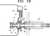
つぎに、図7Bを参照すると、カセット10をアーマチュア内に挿入するときに、カップリングのオーリング64が、最初に、各プローブボデイ59の内面79に接触して、カセット収容物と図7Aに示したシステムの他の部分との間に漏れがない管路を形成する。カセット10が更に移動することにより、テーパ状のプローブ先端81が、前部ポペットバルブ65に接触し、これにより、圧縮ばね75を圧縮することにより、それを前部ポペットフェースシール71から離れる方向に押圧する。また、カップリングの前部ポペットバルブ65の内方への移動により、カップリングボデイ63の開口77から障害物が除去される。これは、カセット内側に配置されたカップリンブ端部の開口77を介してカセット内側とカセット10外側のカップリング端部の開口端部83との間に通路を形成する(図6参照)。更に、カセット内部は、この後、蒸気滅菌、パージング、乾燥等のために、プローブ59の内側を介して滅菌システムに連通する。
【0043】
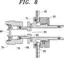
また、カップリング45は、カセット蓋3の適切な閉鎖を可能とし、停電あるいは使用者の介入があった場合に、加圧されたカセットをシステムから外すのを可能とするために、圧力逃し装置として機能する。つぎに、図8を参照すると、カセット蓋3を閉じるときに、第1リップ17がカセットトレー壁35に接触すると、シーリングが有効である(図3B参照)。カセット10内の空気は、カセット蓋3がさらに閉じるのに抗する。カップリング45の圧縮ばね75は、所定のカセット圧力を克服するように設計されている。カセット圧力が所定の限度を越えると、圧縮ばね75は、圧縮され、これにより、後部ポペットバルブ69が後部ポペットフェースシール73から離れる方向に移動するのを可能とし、したがって、カセット圧力が逃げる通路を形成する。カップリングのこの圧力逃し特性は、カセットが加圧され、障害が滅菌サイクルであった場合にも適用され、カセットの除去が望ましいとみなされる。圧力逃し装置は、カセット壁に別個の弁として、あるいは、上述のようにカップリングの一部として設けることができる。
【0044】
デュアルポペットカップリング構造も、カセット内の器具の無菌搬送および保管を許容する。滅菌サイクルが完了すると、カセットは、探触子ないしプローブ59から引離され、システムから外される。再度図7Aを参照すると、カセットがプローブ59から取外されるときに、前部ポペットバルブ65は、カップリングの開口77をシールするその普通の位置に戻り、カップリングのオーリング64は、プローブボデイ面79に係合し続ける。したがって、カセット10内の無菌環境は、カセットを除去するときに、危うくされない。カップリングのオーリング64がプローブボデイ面79から外されるときに、カセット収容物は、再汚染を防止するために、バルブ65の閉鎖動により既にシールされている。
【0045】
ステンレススチールのカセットが滅菌サイクルの最終乾燥段階中に加熱されるために、カセットは、システムから外したとき、触れたときに依然として温かい。カセットが大気温度に冷却すると、カセット内の空気の容量が減少し、その結果、カセット内に真空が徐々に蓄積される。
【0046】
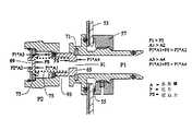
上述の両方向シールおよびカップリングは、この内部の低真空を維持する。図9は、デュアルポペットカップリングがカセットの冷却により形成される低真空をいかに維持するかを示している。カセット内の圧力が冷却のために減少すると、カセット圧力P2は、大気圧P1より小さい。前部ポペットバルブ65は、中央開口91を有しているために、前部および後部ポペットバルブ93間のスペースも圧力P1に晒される。カセットの内側に対向する後部ポペットバルブの表面積A2も、カセットの外側に対向する後部ポペットバルブの表面積A1より小さい。したがって、圧力P1により表面積A1に形成される力、即ち、P1*A1は、圧力P2により表面積A2に形成される力、即ち、P2*A2より大きい。P1*A1>P2*A2+圧縮ばねにより形成される追加の力FSで、後部ポペットルブ69は、後部ポペットフェースシール73に押圧され、そのインターフェースから空気が漏れるのを防止する。同様に、カセットに対向する前部ポペットバルブ65の表面積A3は、大気に対向する前部ポペットバルブの表面積A4より大きいために、P1*A3+FS>P1*A4である。したがって、前部ポペットバルブ65は、前部ポペットフェースシール71に押圧され、前部ポペットバルブのオーリング67は、カップリングボデイ63に押圧され、このインターフェースから空気が漏れるのを防止して、カセット内の器具の無菌保管および搬送を達成する。
【0047】
余分な熱エネルギーがサイクル中、余分な液体の水を加熱するために必要であるために、全滅菌サイクルを短縮するために、カセット内に存在する復水を有することは望ましくない。滅菌サイクル中、不適当な復水がカセット内に残らないようにするために、モジュラーカセットダクト実施形態100がカセット内に案内される。カセットダクト実施形態100は、シリコーンまたは同様な圧力釜で処理可能な材料から形成されたエルボー部材101を使用し、カップリングボデイ63の凹部105に係合する突起103により、カセットの出口カップリングに取付けられる。他の形態の取付け部材が使用可能である。フィルタ107が、エルボー部材101の底部に取付けられ、復水を除去するときに、異物がシステム内に入るのを防止することができる。ダクト100は、蒸気/水がカップリング開口77に移動する通路/チャンネルを、カセットトレー底部110に十分に近接させて、吸引を発生可能とするために、カセットトレー1の底部に接触しないが、近接するように、設計される。ダクトは、洗浄目的のために、最終使用者により取外すことが可能である。カセットダクトおよびフィルタの双方は、最終使用者により交換可能である。
【0048】
図11は、滅菌された器具の改ざんを防止する構造の好ましい改ざん防止実施形態を示す。糊の付いた、感熱紙のラベル(図示せず)が、好ましくは金属ブラケット111の前部を覆うように、スロット109内に挿入される。滅菌プロセス中、感熱紙の色が、アーマチュアの加熱板により発生する熱によって変化し、カセットが滅菌のためにチャンバ内に配置されたことを示す。操作者がカセットを開いて器具を取出すときに、開口ハンドル113が持上げられ、クロスバー115がラベルを引き裂き、カセット10が開いたことを示す。ラベルリテーナ117は、その上に関連する情報が表示されたラベルを保管することができる。カセット蓋3は、カセット収容物を電子的に体系付け、確認するために、通常のバーコード表示を含んでもよい。
【0049】
また、本発明は、両方向シール自体とパージングおよび蒸気滅菌のために真空を用いる滅菌プロセスおよび装置においてカセットを使用する方法とを含む。これらのプロセスおよび装置において、蒸気滅菌サイクルは、排出操作ないしパージングの目的のために、蒸気および真空を用いる。カセットは、真空および加圧状態の双方のときに、密封された態様で機能することができるために、本発明のカセットは、このプロセスおよび装置に適していることが理想的である。特に、本発明の方法は、カセットとこれを囲むアーマチュアスペースとを、これら2つの間の圧力平衡および空気除去のための真空形成に晒すことを含む。この後、蒸気を使用して空気をパージし、この蒸気は、真空を利用して再び除去される。カセットは、この後、加圧され、器具は、蒸気滅菌状態に晒される。カセット圧力が、この後、除去され、器具は、乾燥され、カセット内の蒸気は真空を利用して除去される。カセットは、この後、装置から除去され、器具の後の使用のために保管されるか、あるいは、器具は即座に使用される。この手順の特定の詳細が、出願人の上記カナダ国特許出願に開示されている。
【0050】
実施形態ではカセット内部への媒体の出入りを制御するポペットバルブについて開示したが、他のバルブ構造を、トレーまたは蓋との関連で使用して、滅菌、保管等中に、カセット内部に対する必要な遮断またはアクセスを提供することができる。同様に、オーリング以外のシール構造を用いて、真空モード、加圧モードおよび保管モードでのカセットの使用を許容することができる。
【0051】
又、実施形態ではカセット内部と滅菌装置との間を連通するためのカップリングボデイ63の一対の開口が図示されているが、より多数または少数の開口を用いることができる。同様に、開口はカップリングボデイ内にあるが、他の位置を用いることができる。更に、エルボー部材が復水の回収を高めるためのダクトとして開示されているが、他の構造を、カセット内部内に配置されたカップリングの開口の向きに応じて用いることができる。
【0052】
カセットトレーに対するカップリングの浮動可能とする取付けは、本発明の1の実施形態であるが、他の浮動構造を用いて、カップリングと変動配置のプローブとの間の係合を可能とすることができる。
【0053】
トレーは、入口と出口とを有するとして記載され、蓋は、開位置と閉位置と中間または加圧位置との間を移動するものとして記載されているが、トレーを、入口および出口を支える蓋と共に種々の位置の間を移動する構造とすることができる。同様に、シールは、トレーまたは蓋のいずれかに配置することができる。
【0054】
このように、上述の本発明の目的のそれぞれおよび全てを充足し、滅菌装置および方法で使用される新規かつ改良されたカセットを提供するその好ましい実施形態に関連して本発明について開示した。
【0055】
本発明の教示から種々の変更、修正および代替えが、その予定されている精神および範囲から逸脱せずに、当業者により考えることができる。本発明は、添付特許請求の範囲に関連してのみ制限されるが、実施態様に限定されるものではない。尚、本願における用語「滅菌」は「殺菌」をも含む広義に解される。
【図面の簡単な説明】
【図1】 本発明のカセットの1の実施形態の正面からの斜視図。
【図2】 明確化のために部材が省略されている、図1のカセットの蓋の斜視図。
【図3A】 開位置のカセットの蓋およびトレーの部分断面図。
【図3B】 蓋が中間または部分的に閉じた位置の図3Aの蓋およびトレーの部分断面図。
【図3C】 蓋が閉じたまたは真空/保管密封状態の図3Aの蓋およびトレーの部分断面図。
【図4A】 図1のカセットが加圧されたときのシールの構造を示す図。
【図4B】 図1のカセットが負圧状態のときのシールの構造を示す図。
【図5】 図1のカセットの後方からの斜視図。
【図6】 図5に示したカップリングの1およびカップリングとインターフェース可能な滅菌装置のプローブの断面図。
【図7A】 カセットが滅菌装置内に挿入された状態のカップリングおよび図6のプローブの断面図。
【図7B】 カセット内部とプローブ内部との間の連通を提供するように係合したプローブおよびカップリングを示す図。
【図8】 圧力逃し弁が作動状態の図6のカップリングを示す図。
【図9】 カセット使用中に存在する力および圧力の詳細を示すキーと関連して図6のカップリングを示す図。
【図10】 本発明のカップリングの他の実施形態の部分断面図。
【図11】 蓋とトレーとの間のインターロック機構を示す、図1のカセットの正面からの部分斜視図。[0001]
BACKGROUND OF THE INVENTION
The present invention is a cassette that can sterilize instruments using both vacuum and steam, and in particular, maintains a sterilization and negative pressure state after sterilization with a seal that enables the cassette to operate between vacuum and pressure conditions. It also relates to a cassette having an inlet and outlet coupling that facilitates sterilization.
[0002]
[Prior art and problems]
In the prior art, various methods and devices for sterilizing medical and dental instruments have been proposed. In general, these sterilization techniques use steam and / or vacuum to purge or evacuate air from the chamber containing the article to be sterilized and apply steam to heat and sterilize the load. One method in which this sterilization is performed uses a pressure cooker. One type of pressure cooker is a relatively large sealed container that contains a predetermined amount of boiling water under pressure. Boiling water is used to purge air from inside the vessel. In other pressure cookers, vacuum is also used for purging or evacuation operations. In either case, problems may develop due to incomplete purging of air and build-up of instrument contaminants on the pressure cooker wall. Also, these pressure cookers are inherently slow to sterilize due to the heavy wall and the large heat capacity of the support structure.
[0003]
The devices disclosed in U.S. Pat. Nos. 5,271,893, 5,290,511 and 5,571,476 to Newman overcome many of the disadvantages of conventional pressure cookers. Eliminate. These patents, which are incorporated herein by reference, disclose a method and apparatus for purging and sterilizing steam using a cassette for sterilization. By using the cassette, no transfer from the interior of the sterilization chamber to the type of auxiliary transport tray or other post-sterilization handling device required by conventional pressure cookers is required. The Newman patent also uses small lightweight units that can be easily used in environments such as small offices.
[0004]
Although the apparatus using cassettes taught in the Newman patent offers significant advantages over conventional steam purging / sterilization pressure cooker technology, these cassettes do not use vacuum as part of the steam sterilization process. Can not. Furthermore, these cassettes do not have a structure for storing sterilized instruments.
[0005]
Furthermore, regardless of the equipment and method used, the demand for shorter sterilization cycles is constantly increasing in the industry.
[0006]
Thus, there is a need for improved sterilizers used in sterilizers and methods, particularly devices that allow for faster sterilization times. The present invention meets these needs by providing cassettes used in sterilization methods and apparatus that use both vacuum and steam and cassettes that can store instruments that have been sterilized over time.
[0007]
A first object of the present invention is to provide a cassette that can be used in a steam sterilization apparatus and method utilizing vacuum and pressurized conditions.
[0008]
Another object of the present invention is to provide a cassette having a structure that maintains sterility for storing steam sterilized instruments.
[0009]
Yet another object of the present invention is to provide a cassette having a seal that allows the cassette to operate under pressure and negative pressure conditions during the sterilization process.
[0010]
Other objects and advantages of the present invention will become apparent in the various description that follows.
[0011]
[Means for Solving the Problems and Effects of the Invention]
In order to achieve the above objects and advantages, the present invention provides a sterilization cassette comprising a tray having an inlet and an outlet connected to a probe of a steam sterilizer capable of sterilizing an instrument supported on a base. The cassette has a lid hinged to the base, which includes a seal disposed along the periphery of the lid. The lid is movable between an open position, a closed position, and an intermediate position, and the lid, seal, and tray form a sterilization chamber when the lid is in the closed position and the intermediate position.
[0012]
Each of the inlet and outlet has a first valve that allows communication between the steam sterilizer and the sterilization chamber. A second valve is formed as part of the cassette to relieve overpressure in the sterilization chamber. The first and second valves also seal the sterilization chamber for storage of sterilized instruments.
[0013]
In one particular configuration, the seal includes a continuous seal body extending along the periphery of the lid, and the first and second lips extend from the seal body and are pivotally connected thereto. A third lip extends from the seal body and is spaced from the second lip to form a channel therebetween. The first and second lips together with the channel form a seal in an intermediate position, and the first, second and second lips form a seal in the closed position.
[0014]
The outlet has at least one opening disposed in the chamber, the at least one opening being spaced from the bottom of the tray. A duct can be attached to the outlet at one end, and the opposite end of the duct located close to the bottom of the tray provides a channel for collecting condensate during steam sterilization of the instrument. Form.
[0015]
Furthermore, in the present invention, each of the inlet and outlet is further movably loaded through the wall of the tray while maintaining a seal between the coupling body and the wall, and the probe and coupling of the sterilizer. A coupling body and seal assembly is provided that enables self-alignment with the body.
[0016]
The cassette also employs a unique seal to maintain sterility when the cassette is removed. In this embodiment, one end of the coupling body is located outside the sterilization chamber and the second end is located inside the sterilization chamber. One end has a sealing device on its peripheral surface. In the sealing device, before opening and closing the first valve, a seal is formed between the peripheral surface and the surface of the probe, and is separated from the wall so as to seal the sterilization chamber from the surroundings.
[0017]
In another specific configuration, the cassette employs a dual valve coupling device, whereby the first and second valves are disposed on the coupling body. The first valve is biased in the closed position and can be opened when a force is applied to the valve face against the biasing force. The second valve is biased in the closed position and is movable to the open position when a force is applied from within the sterilization chamber. The biasing force can be created by a spring disposed between the two valves. The first valve may have a hole in it that communicates between the first opening and the second valve, so that when the sterilization chamber is under vacuum for storage, the spring biasing force and Atmospheric pressure maintains each of the first and second valves in the closed position.
[0018]
The invention also involves a flexible seal for the sterilization cassette and a method of using the cassette as part of a sterilization process using steam and vacuum. A method of steam sterilizing an instrument comprises placing the instrument in a sterilization chamber and connecting its inlet and outlet to a probe of a steam sterilizer. The instrument is subjected to a steam sterilization cycle using pressurized and negative pressure conditions. The cassette is then removed after completion of the steam sterilization cycle and the instrument is stored in the cassette under negative pressure conditions or the instrument is removed from the cassette for use.
[0019]
The present invention also includes a dual configuration dual valve coupling that can be used in other cassette configurations.
[0020]
DETAILED DESCRIPTION OF THE INVENTION
The cassettes of the present invention offer excellent advantages in the field of sterilization instruments such as those used in the medical and dental fields. First, because of the cassette's unique seal, the cassette can be used in a method and apparatus that uses a negative pressure condition to remove air from the cassette prior to steam sterilization and a pressurized condition commonly encountered during steam sterilization. it can.
[0021]
Second, the cassette allows sterilized instruments to be stored in the cassette until ready for use. Therefore, the cassette itself functions not only as a sterilizer but also as a storage device for sterilized instruments.
[0022]
Third, the cassette structure maintains sterile air inside the cassette as it is removed from the sterilizer.
[0023]
It should also be understood that the cassettes of the present invention can be used in devices and methods that use both vacuum and steam as part of sterilization. In particular, the cassette has a lid and seal assembly that moves between two positions relative to the tray. The tray has inlet and outlet couplings that facilitate exposing the inside of the cassette to vacuum and steam conditions as part of the sterilization process.
[0024]
The first position of the lid is a closed position, whereby the inside of the cassette is sealed from the outside during a sterilization process or in storage mode when in a negative pressure condition or when sterilized.
[0025]
The second position of the lid is formed when the inside is pressurized and the lid is lifted against the tray. The seal blocks the inside of the cassette from the outside even when the lid is not in the first position or the closed position.
[0026]
The inlet and outlet couplings have a structure that ensures that removal of the cassette from the sterilizer does not compromise the inside of the sterilized cassette after the instrument has been sterilized. This structure uses a valve and a seal for each coupling, and a set of seals is placed outside the cassette. The outer seal blocks the inside of the cassette when the coupling is removed from the probe that supplies or vacuums the sterilizer vapor.
[0027]
The inlet and outlet couplings also employ a pressure relief valve that allows the release of unwanted pressure inside the cassette. The pressure relief valve also works with other valves in the coupling to maintain a negative pressure inside the cassette after the sterilization process is complete. By maintaining this state, the sterilized instrument can be stored in the cassette for an extended period of time. Thus, the instrument can be pre-sterilized and stored until needed.
[0028]
FIG. 1 shows a
[0029]
When used in conjunction with a sterilization apparatus and method that employs a frame-like or chamber-like structure, hereinafter referred to as an armature, in the cassette of the present invention, the combined system is for sterilization of dental and medical instruments. It can withstand both the pressure and vacuum required for Moreover, at the same time, the lightweight cassette provides instrument portability and aseptic transport / storage. The sterilization system creates a vacuum in both the cassette and the space formed by the armature surrounding the cassette, so that in all cases of vacuum formation, the differential pressure between the cassette and the armature is zero. Preferred cassette embodiments function under vacuum. Preferred cassette embodiments work under pressure because the cassette transmits most structural loads to a structurally superior armature during pressurization. Thus, inappropriate stresses do not act on the cassette itself during the sterilization cycle. This sterilizer is disclosed in Canadian Patent Application No. 2268042 to the present applicant.
[0030]
The
[0031]
2 is connected to the
[0032]
A tight seal is formed between the
[0033]
FIG. 3A shows a cross section of a
[0034]
When the
[0035]
When the
[0036]
During the pressurization phase of the sterilization cycle shown in FIG. 4A, steam is injected into the
[0037]
The upward movement of the
[0038]
At the end of the sterilization cycle, hot air in the
[0039]
The cassette of the present invention also includes inlets and outlets that allow inflow and outflow of steam, air, etc. as part of the steam sterilization process. In one embodiment, the steam flows into the cassette via a coupling in the
[0040]
FIG. 6 shows a preferred coupling embodiment and a preferred counterpart probe embodiment of the sterilization system. Each coupling is attached to the cassette tray by an O-
[0041]
FIG. 7A shows a
[0042]
Referring now to FIG. 7B, when inserting the
[0043]
The
[0044]
The dual poppet coupling structure also allows for aseptic transport and storage of the instrument in the cassette. When the sterilization cycle is complete, the cassette is pulled away from the probe or probe 59 and removed from the system. Referring again to FIG. 7A, when the cassette is removed from the
[0045]
Because the stainless steel cassette is heated during the final drying phase of the sterilization cycle, the cassette is still warm when touched when removed from the system. As the cassette cools to ambient temperature, the volume of air in the cassette decreases and as a result, a vacuum builds up gradually in the cassette.
[0046]
The bidirectional seal and coupling described above maintain this low internal vacuum. FIG. 9 shows how the dual poppet coupling maintains the low vacuum created by the cooling of the cassette. When the pressure in the cassette decreases due to cooling, the cassette pressure P2 is less than the atmospheric pressure P1. Since the
[0047]
It is not desirable to have the condensate present in the cassette to shorten the entire sterilization cycle, since extra heat energy is needed to heat excess liquid water during the cycle. Modular cassette duct embodiment 100 is guided into the cassette to prevent improper condensate from remaining in the cassette during the sterilization cycle. The cassette duct embodiment 100 uses an
[0048]
FIG. 11 shows a preferred anti-tampering embodiment of a structure that prevents tampering of sterilized instruments. A glued thermal paper label (not shown) is inserted into the
[0049]
The present invention also includes a bidirectional seal itself and a method of using the cassette in a sterilization process and apparatus that uses a vacuum for purging and steam sterilization. In these processes and equipment, the steam sterilization cycle uses steam and vacuum for the purpose of draining operations or purging. Ideally, the cassette of the present invention is suitable for this process and apparatus because the cassette can function in a sealed manner when both in vacuum and pressurized conditions. In particular, the method of the present invention involves exposing the cassette and the surrounding armature space to a pressure balance between the two and a vacuum formation for air removal. After this, air is purged using steam, which is removed again using a vacuum. The cassette is then pressurized and the instrument is exposed to steam sterilization. The cassette pressure is then removed, the instrument is dried, and the vapor in the cassette is removed using a vacuum. The cassette is then removed from the device and stored for later use of the instrument or the instrument is used immediately. Specific details of this procedure are disclosed in the applicant's Canadian patent application.
[0050]
Although embodiments have disclosed poppet valves that control the entry and exit of media into the cassette, other valve structures may be used in conjunction with trays or lids to provide the necessary blockage to the cassette interior during sterilization, storage, etc. Or access can be provided. Similarly, seal structures other than O-rings can be used to allow the cassette to be used in vacuum mode, pressure mode and storage mode.
[0051]
In the embodiment, a pair of openings of the
[0052]
The floatable attachment of the coupling to the cassette tray is one embodiment of the present invention, but other floating structures may be used to allow engagement between the coupling and the variable placement probe. Can do.
[0053]
The tray is described as having an inlet and an outlet and the lid is described as moving between an open position, a closed position, and an intermediate or pressurized position, but the tray is a lid that supports the inlet and outlet. Moreover, it can be set as the structure which moves between various positions. Similarly, the seal can be placed on either the tray or the lid.
[0054]
Thus, the present invention has been disclosed in connection with its preferred embodiment which satisfies each and all of the above-mentioned objects of the present invention and provides a new and improved cassette for use in sterilization apparatus and methods.
[0055]
Various changes, modifications and alternatives from the teachings of the invention may be devised by those skilled in the art without departing from the intended spirit and scope. The present invention is limited only in connection with the appended claims, but is not limited to the embodiments. The term “sterilization” in the present application is understood in a broad sense including “sterilization”.
[Brief description of the drawings]
FIG. 1 is a front perspective view of one embodiment of a cassette of the present invention.
FIG. 2 is a perspective view of the lid of the cassette of FIG. 1, with members omitted for clarity.
FIG. 3A is a partial cross-sectional view of the cassette lid and tray in an open position.
3B is a partial cross-sectional view of the lid and tray of FIG. 3A with the lid in the middle or partially closed position.
3C is a partial cross-sectional view of the lid and tray of FIG. 3A with the lid closed or vacuum / storage sealed.
4A is a view showing a structure of a seal when the cassette of FIG. 1 is pressurized. FIG.
4B is a view showing a seal structure when the cassette of FIG. 1 is in a negative pressure state. FIG.
FIG. 5 is a perspective view from the rear of the cassette of FIG. 1;
6 is a cross-sectional view of the
7A is a cross-sectional view of the coupling and probe of FIG. 6 with the cassette inserted into the sterilizer.
FIG. 7B shows the probe and coupling engaged to provide communication between the cassette interior and the probe interior.
8 shows the coupling of FIG. 6 with the pressure relief valve activated.
FIG. 9 shows the coupling of FIG. 6 in conjunction with a key showing details of the forces and pressures present during cassette use.
FIG. 10 is a partial cross-sectional view of another embodiment of the coupling of the present invention.
FIG. 11 is a partial perspective view from the front of the cassette of FIG. 1 showing an interlock mechanism between the lid and the tray.
Claims (20)
Translated fromJapanese(b) 前記ベースにヒンジ止めされる蓋とを備え、この蓋は、蓋の周部に沿って配置されたシールを有し、開位置と、閉位置と、中間位置との間を移動可能で、この蓋が閉位置および中間位置にあるときに、この蓋とシールとトレーとが滅菌チャンバを形成し、更に、
(c) 入口および出口のそれぞれが蒸気滅菌装置と該滅菌チャンバとの間を連通可能な第1弁と、該カセットの一部として設けられ、該滅菌チャンバの余分な圧力を解放する第2弁とを有し、これらの第1,第2弁は更に該滅菌チャンバをシールし、滅菌した器具を保管する、滅菌カセット。(A) a tray having an inlet and an outlet for connecting to a probe of a steam sterilizer for sterilizing an instrument supported on the base;
(B) a lid hinged to the base, the lid having a seal disposed along the periphery of the lid and movable between an open position, a closed position, and an intermediate position And when the lid is in the closed and intermediate positions, the lid, the seal and the tray form a sterilization chamber;
(C) a first valve capable of communicating between the steam sterilizer and the sterilization chamber, each having an inlet and an outlet, and a second valve provided as part of the cassette to release excess pressure in the sterilization chamber And the first and second valves further seal the sterilization chamber and store sterilized instruments.
i)該蓋の周部に沿って延びる連続したシールボディと、
ii)該シールボディから延びかつこれに枢動可能に連結された第1,第2リップと、
iii)前記第2リップから離隔して該シールボディから延び、その間にチャンネルを形成する第3リップと、を備え、
iv)前記第1,第2リップは前記中間位置でシールし、第3リップは前記閉位置でシールする、請求項1に記載のカセット。The seal further includes
i) a continuous seal body extending along the periphery of the lid;
ii) first and second lips extending from and pivotally connected to the seal body;
iii) a third lip extending from the seal body spaced apart from the second lip and forming a channel therebetween,
iv) said first, second lip seals in the intermediate position, the third lip seals in the closed position, the cassette according to claim1.
i)該滅菌カセットの蓋に装架可能な連続したシールボディと、
ii)該シールボディから延び、このシールボディに枢動可能に連結された第1,第2リップと、
iii)該シールボディから延び、前記第2リップから離隔してその間にチャンネルを形成する第3リップと、
iv)前記第1,第2リップは該滅菌カセットと協働して、トレーと該蓋とが第1位置にあるときにシールを形成し、前記第1,第2,第3リップは該滅菌カセットと協働して、該可撓性シールが閉位置にあるときにシールを形成することと、
よりなる可撓性シール。A flexible seal for a sterilization cassette,
i) a continuous seal body mountable on the lid of the sterilization cassette;
ii) first and second lips extending from the seal body and pivotally connected to the seal body;
iii) a third lip extending from the seal body and spaced apart from the second lip to form a channel therebetween;
iv) The first and second lips cooperate with the sterilization cassette to form a seal when the tray and the lid are in the first position, and the first, second and third lips are the sterilization Cooperating with the cassette to form a seal when the flexible seal is in a closed position;
A flexible seal.
Applications Claiming Priority (3)
| Application Number | Priority Date | Filing Date | Title |
|---|---|---|---|
| CA002268042ACA2268042A1 (en) | 1999-04-06 | 1999-04-06 | Apparatus and method for steam sterilization of medical and dental instruments |
| CA2,268,042 | 1999-04-06 | ||
| PCT/CA2000/000376WO2000059552A1 (en) | 1999-04-06 | 2000-04-06 | Cassette for vacuum and steam sterilization apparatus |
Publications (2)
| Publication Number | Publication Date |
|---|---|
| JP2002540851A JP2002540851A (en) | 2002-12-03 |
| JP4656730B2true JP4656730B2 (en) | 2011-03-23 |
Family
ID=4163436
Family Applications (2)
| Application Number | Title | Priority Date | Filing Date |
|---|---|---|---|
| JP2000609113AExpired - LifetimeJP4656730B2 (en) | 1999-04-06 | 2000-04-06 | Cassette for vacuum and steam sterilizer |
| JP2000609114AExpired - LifetimeJP4573079B2 (en) | 1999-04-06 | 2000-04-06 | Sterilizer that vents air by evacuation |
Family Applications After (1)
| Application Number | Title | Priority Date | Filing Date |
|---|---|---|---|
| JP2000609114AExpired - LifetimeJP4573079B2 (en) | 1999-04-06 | 2000-04-06 | Sterilizer that vents air by evacuation |
Country Status (6)
| Country | Link |
|---|---|
| US (2) | US7641852B1 (en) |
| EP (2) | EP1175231B1 (en) |
| JP (2) | JP4656730B2 (en) |
| CA (4) | CA2268042A1 (en) |
| DE (2) | DE60004509T2 (en) |
| WO (2) | WO2000059553A1 (en) |
Families Citing this family (55)
| Publication number | Priority date | Publication date | Assignee | Title |
|---|---|---|---|---|
| CA2268042A1 (en) | 1999-04-06 | 2000-10-06 | Scican, A Division Of Lux & Zwingenberger Ltd. | Apparatus and method for steam sterilization of medical and dental instruments |
| JP4668453B2 (en)* | 2001-04-27 | 2011-04-13 | オリンパス株式会社 | Autoclave equipment |
| US7641864B2 (en) | 2001-06-15 | 2010-01-05 | Avure Technologies Incorporated | Thermal sensor connector for pressure vessel |
| JP4257065B2 (en)* | 2002-02-28 | 2009-04-22 | オリンパス株式会社 | Sterilizer |
| JP2003260118A (en)* | 2002-03-11 | 2003-09-16 | Olympus Optical Co Ltd | Sterilization apparatus |
| ITMI20030579A1 (en)* | 2003-03-24 | 2004-09-25 | M O Com S R L | BOILER BODY FOR STEAM STERILIZERS, IN PARTICULAR STERILIZERS FOR DENTAL INSTRUMENTS, AND PROCEDURE FOR ITS REALIZATION |
| PL1853325T3 (en)* | 2005-01-25 | 2009-11-30 | Bat Holding Aps | A method and an apparatus for sterilization of an item |
| ITMI20050349A1 (en)* | 2005-03-07 | 2006-09-08 | W & H Sterilization Srl | AUTOCLAVE PERFECTED WITH A COMBINED WORKING CYCLE CONTAINER TO BE USED IN SUCH AN AUTOCLAVE AND COMPLETE STERILIZATION SYSTEM USING THIS CONTAINER |
| GB2439048A (en)* | 2006-06-15 | 2007-12-19 | Eschmann Holdings Ltd | Autoclave and sterilisation process |
| US20090081090A1 (en)* | 2007-09-26 | 2009-03-26 | Dayman Jeffrey G | Sterilizer with modular pressure housing for a sterilization chamber |
| US20090081089A1 (en)* | 2007-09-26 | 2009-03-26 | Dayman Jeffrey G | Fluid reservoir and receiver assembly |
| DE102008020586A1 (en) | 2008-04-24 | 2009-10-29 | Kaltenbach & Voigt Gmbh | Apparatus and method for disinfecting, sterilizing and / or maintaining medical, in particular dental, instruments |
| JP2008264571A (en)* | 2008-06-16 | 2008-11-06 | Olympus Corp | Sterilization container and sterilization apparatus |
| DE102010002030A1 (en) | 2009-03-20 | 2010-10-14 | Kaltenbach & Voigt Gmbh | Device for disinfecting, sterilizing and / orcare of medical, in particular dental, instruments |
| DE102010037659A1 (en)* | 2010-09-20 | 2012-03-22 | Aesculap Ag | A sterile container |
| USD668349S1 (en)* | 2011-02-25 | 2012-10-02 | Scican Ltd. | Cassette sterilizer |
| FI20115350A0 (en) | 2011-04-12 | 2011-04-12 | Steris Europe Inc | A device for separating a solid from a biowaste suspension |
| DE102011086848A1 (en)* | 2011-11-22 | 2013-05-23 | Melag Medizintechnik Ohg | Movable part with means for attaching a container for medical and dental instruments in an autoclave |
| DE102012101833A1 (en)* | 2012-03-05 | 2013-09-05 | Aesculap Ag | Surgical sterilization container pan and surgical sterilization container with a sterilization container pan |
| DE102012101832A1 (en) | 2012-03-05 | 2013-09-05 | Aesculap Ag | Surgical sterilization container and surgical fluid extraction device |
| US10760853B1 (en)* | 2012-03-15 | 2020-09-01 | Crosstex International, Inc. | Automated thermal exchange system for autoclave sterilizer |
| DE102012102370A1 (en)* | 2012-03-20 | 2013-09-26 | Aesculap Ag | Medical seal and medical sterilization container |
| US8815174B2 (en)* | 2012-08-17 | 2014-08-26 | American Sterilizer Company | Steam sterilizer |
| CN105377312B (en) | 2013-03-13 | 2018-05-22 | 史赛克公司 | Sterilization containers that provide an indication of whether the sterilized surgical instruments in the container have been properly sterilized |
| KR101451309B1 (en)* | 2013-06-21 | 2014-10-15 | 주식회사 신흥 | Storage case for sterilization |
| AU2015256267B2 (en)* | 2014-05-06 | 2017-08-10 | American Sterilizer Company | Sterilizer |
| DE102015100455A1 (en)* | 2015-01-14 | 2016-07-14 | Aesculap Ag | Medical-technical sterilization container with passive after-drying |
| DE102015100454A1 (en)* | 2015-01-14 | 2016-07-14 | Aesculap Ag | Medical-technical sterilization container with active after-drying |
| WO2016138482A1 (en)* | 2015-02-26 | 2016-09-01 | K&K Lukas LLC | Dry heat sanitizer and method of use |
| DE102015106641A1 (en)* | 2015-04-29 | 2016-11-03 | Aesculap Ag | Sterilization System, Sterilization Tank, Sterilization Tank Cradle and Sterilizer |
| KR101878459B1 (en)* | 2015-09-24 | 2018-07-13 | 유동수 | Sterilization system by high pressure steam |
| US9671167B1 (en) | 2015-11-13 | 2017-06-06 | American Sterilizer Company | Process for reducing the temperature of an effluent stream flowing out of a sterilization chamber |
| DE102016110572A1 (en)* | 2016-06-08 | 2017-12-14 | B. Braun Melsungen Ag | Medical-technical treatment chamber in lightweight construction |
| DE102016112885A1 (en) | 2016-07-13 | 2018-01-18 | Aesculap Ag | Medical container with tilted lid seal |
| IT201600131201A1 (en)* | 2016-12-27 | 2018-06-27 | W & H Sterilization Srl | PERFORMED THERMODYNAMIC CYCLE STERILIZATION SYSTEM AND RELATED METHOD |
| IT201700019118A1 (en) | 2017-02-21 | 2018-08-21 | Cefla Soc Cooperativa | MODULAR PORTATRAY FOR AUTOCLAVE |
| IT201700099949A1 (en)* | 2017-09-06 | 2019-03-06 | Fater Spa | STERILIZATION APPLIANCE, IN PARTICULAR FOR THE STERILIZATION OF POST-CONSUMPTION ABSORBENT SANITARY PRODUCTS |
| CN107470233B (en)* | 2017-09-12 | 2020-04-28 | 中国人民解放军第三军医大学第三附属医院 | Endoscope cleaning device |
| US12129065B2 (en)* | 2018-03-23 | 2024-10-29 | Log10 B.V. | Method and system for reprocessing reusable medical instruments |
| US10568485B2 (en)* | 2018-07-12 | 2020-02-25 | Marilou Johnson | Shoe disinfecting assembly |
| WO2020190459A1 (en)* | 2019-03-19 | 2020-09-24 | Medivators Inc. | Vented endoscope tray covers, systems and methods |
| EP4497409A3 (en) | 2019-06-20 | 2025-06-25 | Medivators Inc. | Endoscope storage tray having apertures and method of use |
| EP3986317B1 (en) | 2019-06-20 | 2024-09-18 | Medivators Inc. | Endoscope storage system |
| WO2020256989A1 (en) | 2019-06-20 | 2020-12-24 | Medivators Inc. | Absorbent liner, systems and methods of use |
| USD868992S1 (en) | 2019-07-17 | 2019-12-03 | Shenzhen Jienuoyi Science And Technology Co., Ltd | UVC LED sterilizer |
| CN111110883B (en)* | 2020-01-21 | 2024-06-28 | 山东新华医疗器械股份有限公司 | Clip type pulsation vacuum sterilizer |
| AU2021225770B2 (en) | 2020-02-25 | 2025-02-27 | Medivators Inc. | Stackable endoscope storage tray and method of use |
| CN111776609A (en)* | 2020-06-24 | 2020-10-16 | 天津市宝坻区人民医院 | Medical record cleaning and sterilizing device for hospital medical record management |
| CN111888492A (en)* | 2020-07-31 | 2020-11-06 | 宁波市海曙莱富医疗科技有限公司 | Sterilization device |
| CN112675321A (en)* | 2020-12-19 | 2021-04-20 | 张家港华菱医疗设备股份公司 | Steam sterilizing cabinet |
| US20220373088A1 (en)* | 2021-05-21 | 2022-11-24 | Scican Ltd. | Door seal |
| CN113209323A (en)* | 2021-05-25 | 2021-08-06 | 秦皇岛燕大源达机电科技股份有限公司 | Vacuum tube type steam sterilizer and sterilization method thereof |
| CN115300645B (en)* | 2022-08-10 | 2024-02-20 | 浙江迈亚塔菌检智能科技有限公司 | Steam sterilization device |
| EP4593893A1 (en)* | 2022-09-30 | 2025-08-06 | American Sterilizer Company | Runoff seal for hinged lid of medical device processor |
| EP4431119A1 (en) | 2023-03-14 | 2024-09-18 | MELAG Medizintechnik GmbH & Co. KG | Method for controlling the level of feedwater in a steam sterilizer and steam sterilizer |
Family Cites Families (28)
| Publication number | Priority date | Publication date | Assignee | Title |
|---|---|---|---|---|
| US1746522A (en)* | 1927-07-12 | 1930-02-11 | Robert A Carleton | Low-tension fluid-heating apparatus |
| US2258746A (en)* | 1941-02-08 | 1941-10-14 | Simon Dickman | Steam generator |
| US2868616A (en)* | 1954-04-14 | 1959-01-13 | Edward J Poitras | Steam sterilization method |
| US3086263A (en)* | 1959-07-10 | 1963-04-23 | Huber Johann | Sterilizing apparatus |
| US3834872A (en) | 1972-07-03 | 1974-09-10 | Sybron Corp | Tabletop steam sterilizer |
| US4105407A (en)* | 1975-04-24 | 1978-08-08 | Sanderson Roger S | Sterilizing and storing medical items |
| JPS5922041Y2 (en)* | 1978-08-15 | 1984-07-02 | 株式会社東芝 | airtight container |
| JPS57170258A (en)* | 1981-04-13 | 1982-10-20 | Olympus Optical Co | Therapeutic device enclosing container |
| US4759909A (en)* | 1983-02-23 | 1988-07-26 | Joslyn Valve Corp. | Methods and apparatus for steam sterilization |
| US4783321A (en) | 1984-12-18 | 1988-11-08 | Instrumed, Inc. | Sterlization container system |
| US5160700A (en)* | 1989-10-04 | 1992-11-03 | H. W. Andersen Products, Inc. | Sterilizing system and method |
| CA2029682C (en)* | 1989-11-24 | 1995-10-10 | Duncan Newman | Method and apparatus for steam sterilization of articles |
| US5271893A (en) | 1989-11-24 | 1993-12-21 | Duncan Newman | Apparatus for steam sterilization of articles |
| US5368821A (en)* | 1990-03-28 | 1994-11-29 | Mdt Corporation | Sealable sterilizer cassette |
| US5207237A (en) | 1990-07-20 | 1993-05-04 | Kew Import/Export Inc. | Ozoneated liquid system |
| US5145642A (en)* | 1991-01-31 | 1992-09-08 | Mdt Corporation | Load compensated water fill for a table top sterilizer |
| US5310524A (en) | 1992-02-11 | 1994-05-10 | Minntech Corporation | Catheter reprocessing and sterilizing system |
| EP0583465A1 (en)* | 1992-03-13 | 1994-02-23 | American Sterilizer Company | Sterilization apparatus and method for multicomponent sterilant |
| US5266275A (en) | 1992-09-04 | 1993-11-30 | Faddis Chris G | Ozone sterilization system secondary safety chamber |
| US5344622A (en) | 1993-04-03 | 1994-09-06 | Cyclo3 pss Medical Systems, Inc. | Ozone sterilization system vapor humidification component with disposable water source |
| US5364590A (en) | 1993-05-07 | 1994-11-15 | American Sterlizer Company | Method for sterilization of objects |
| US5533539A (en)* | 1993-07-15 | 1996-07-09 | Siemens Aktiengesellschaft | Apparatus for intensive cleaning of medical articles |
| DE9310601U1 (en)* | 1993-07-15 | 1993-09-02 | Siemens AG, 80333 München | Cassette for holding medical, in particular dental, instruments |
| US5759502A (en) | 1997-01-31 | 1998-06-02 | Sterilization Cassette Systems, Inc. | Instrument cassette having a mechanism to prevent lateral movement of an instrument support relative to an instrument support holder |
| US6066294A (en)* | 1997-08-21 | 2000-05-23 | Ethicon, Inc. | Multi-compartment sterilization system |
| DE19714298A1 (en) | 1997-04-07 | 1998-10-08 | Scican Division Of Lux & Zwing | Adapter for a sterilization container in the form of a cassette |
| US6010670A (en) | 1998-06-03 | 2000-01-04 | Berry, Jr.; Bernie B. | Sterilization assembly for instrument case |
| CA2268042A1 (en) | 1999-04-06 | 2000-10-06 | Scican, A Division Of Lux & Zwingenberger Ltd. | Apparatus and method for steam sterilization of medical and dental instruments |
- 1999
- 1999-04-06CACA002268042Apatent/CA2268042A1/ennot_activeAbandoned
- 2000
- 2000-04-06JPJP2000609113Apatent/JP4656730B2/ennot_activeExpired - Lifetime
- 2000-04-06CACA002365828Apatent/CA2365828C/ennot_activeExpired - Lifetime
- 2000-04-06WOPCT/CA2000/000377patent/WO2000059553A1/enactiveIP Right Grant
- 2000-04-06JPJP2000609114Apatent/JP4573079B2/ennot_activeExpired - Lifetime
- 2000-04-06CACA002365829Apatent/CA2365829C/ennot_activeExpired - Lifetime
- 2000-04-06CACA2614685Apatent/CA2614685C/ennot_activeExpired - Lifetime
- 2000-04-06WOPCT/CA2000/000376patent/WO2000059552A1/enactiveIP Right Grant
- 2000-04-06DEDE60004509Tpatent/DE60004509T2/ennot_activeExpired - Lifetime
- 2000-04-06EPEP00916720Apatent/EP1175231B1/ennot_activeExpired - Lifetime
- 2000-04-06EPEP00916719Apatent/EP1165150B1/ennot_activeExpired - Lifetime
- 2000-04-06DEDE60011879Tpatent/DE60011879T8/enactiveActive
- 2000-04-06USUS09/958,035patent/US7641852B1/ennot_activeExpired - Fee Related
- 2011
- 2011-04-29USUS13/097,230patent/US8795603B2/ennot_activeExpired - Fee Related
Also Published As
| Publication number | Publication date |
|---|---|
| CA2365829A1 (en) | 2000-10-12 |
| CA2365829C (en) | 2007-08-07 |
| JP4573079B2 (en) | 2010-11-04 |
| CA2268042A1 (en) | 2000-10-06 |
| EP1165150B1 (en) | 2004-06-30 |
| EP1165150A1 (en) | 2002-01-02 |
| CA2365828C (en) | 2008-01-29 |
| US20110262301A1 (en) | 2011-10-27 |
| CA2614685C (en) | 2010-03-16 |
| DE60004509T2 (en) | 2004-05-19 |
| US8795603B2 (en) | 2014-08-05 |
| EP1175231A1 (en) | 2002-01-30 |
| DE60011879D1 (en) | 2004-08-05 |
| US7641852B1 (en) | 2010-01-05 |
| WO2000059553A1 (en) | 2000-10-12 |
| DE60011879T2 (en) | 2005-08-25 |
| JP2002540851A (en) | 2002-12-03 |
| EP1175231B1 (en) | 2003-08-13 |
| JP2002540852A (en) | 2002-12-03 |
| DE60004509D1 (en) | 2003-09-18 |
| CA2614685A1 (en) | 2000-10-12 |
| DE60011879T8 (en) | 2005-12-15 |
| WO2000059552A1 (en) | 2000-10-12 |
| CA2365828A1 (en) | 2000-10-12 |
Similar Documents
| Publication | Publication Date | Title |
|---|---|---|
| JP4656730B2 (en) | Cassette for vacuum and steam sterilizer | |
| US4372921A (en) | Sterilized storage container | |
| US5364602A (en) | Sterilization system | |
| US4754595A (en) | Method of sterilizing and storing articles | |
| US4416417A (en) | Sterilized storage container | |
| US4498508A (en) | Container filler | |
| US4247517A (en) | Sterilized storage container | |
| US4671943A (en) | Sterilization and storage container | |
| US4583643A (en) | Sterile bag | |
| US4584182A (en) | Sterilized storage container | |
| AU2010214151B2 (en) | Sterilisation services apparatus and method of sterilisation | |
| KR920700998A (en) | Device to vacuum the plastic bag | |
| US8236253B2 (en) | Portable sterilizing apparatus for surgical and dental instruments | |
| US20130280134A1 (en) | Sterilization container | |
| CN112672769B (en) | Condensate drain valve | |
| CN106999616A (en) | Sterilization container, the method for sterilizing and bactericidal unit | |
| US5470546A (en) | Apparatus for storing and sterilizing bio-hazardous waste | |
| EP0044340B1 (en) | Pressure and temperature responsive device and apparatus for containing items to be sterilized | |
| US6048502A (en) | Water recirculating sterilization mechanism | |
| WO1979000077A1 (en) | Sterilized storage container and method | |
| US4374570A (en) | Sterilized storage container | |
| CN211610861U (en) | Card type pulsation vacuum sterilizer | |
| US20150320896A1 (en) | Sterilizer | |
| US4558632A (en) | Sterilized storage container | |
| JPH01502399A (en) | Flash sterilization container |
Legal Events
| Date | Code | Title | Description |
|---|---|---|---|
| A621 | Written request for application examination | Free format text:JAPANESE INTERMEDIATE CODE: A621 Effective date:20070406 | |
| A977 | Report on retrieval | Free format text:JAPANESE INTERMEDIATE CODE: A971007 Effective date:20081009 | |
| A131 | Notification of reasons for refusal | Free format text:JAPANESE INTERMEDIATE CODE: A131 Effective date:20081021 | |
| A601 | Written request for extension of time | Free format text:JAPANESE INTERMEDIATE CODE: A601 Effective date:20090116 | |
| A602 | Written permission of extension of time | Free format text:JAPANESE INTERMEDIATE CODE: A602 Effective date:20090123 | |
| A521 | Request for written amendment filed | Free format text:JAPANESE INTERMEDIATE CODE: A523 Effective date:20090421 | |
| A131 | Notification of reasons for refusal | Free format text:JAPANESE INTERMEDIATE CODE: A131 Effective date:20090602 | |
| A601 | Written request for extension of time | Free format text:JAPANESE INTERMEDIATE CODE: A601 Effective date:20090828 | |
| A602 | Written permission of extension of time | Free format text:JAPANESE INTERMEDIATE CODE: A602 Effective date:20090904 | |
| A521 | Request for written amendment filed | Free format text:JAPANESE INTERMEDIATE CODE: A523 Effective date:20091201 | |
| A131 | Notification of reasons for refusal | Free format text:JAPANESE INTERMEDIATE CODE: A131 Effective date:20100803 | |
| A521 | Request for written amendment filed | Free format text:JAPANESE INTERMEDIATE CODE: A523 Effective date:20101102 | |
| TRDD | Decision of grant or rejection written | ||
| A01 | Written decision to grant a patent or to grant a registration (utility model) | Free format text:JAPANESE INTERMEDIATE CODE: A01 Effective date:20101130 | |
| A01 | Written decision to grant a patent or to grant a registration (utility model) | Free format text:JAPANESE INTERMEDIATE CODE: A01 | |
| A61 | First payment of annual fees (during grant procedure) | Free format text:JAPANESE INTERMEDIATE CODE: A61 Effective date:20101221 | |
| FPAY | Renewal fee payment (event date is renewal date of database) | Free format text:PAYMENT UNTIL: 20140107 Year of fee payment:3 | |
| R150 | Certificate of patent or registration of utility model | Ref document number:4656730 Country of ref document:JP Free format text:JAPANESE INTERMEDIATE CODE: R150 Free format text:JAPANESE INTERMEDIATE CODE: R150 | |
| R250 | Receipt of annual fees | Free format text:JAPANESE INTERMEDIATE CODE: R250 | |
| R250 | Receipt of annual fees | Free format text:JAPANESE INTERMEDIATE CODE: R250 | |
| R250 | Receipt of annual fees | Free format text:JAPANESE INTERMEDIATE CODE: R250 | |
| R250 | Receipt of annual fees | Free format text:JAPANESE INTERMEDIATE CODE: R250 | |
| R250 | Receipt of annual fees | Free format text:JAPANESE INTERMEDIATE CODE: R250 | |
| R250 | Receipt of annual fees | Free format text:JAPANESE INTERMEDIATE CODE: R250 | |
| R250 | Receipt of annual fees | Free format text:JAPANESE INTERMEDIATE CODE: R250 | |
| EXPY | Cancellation because of completion of term |