JP4656456B2 - Lane marking device, lane marking detection method, and lane marking detection program - Google Patents
Lane marking device, lane marking detection method, and lane marking detection programDownload PDFInfo
- Publication number
- JP4656456B2 JP4656456B2JP2008271813AJP2008271813AJP4656456B2JP 4656456 B2JP4656456 B2JP 4656456B2JP 2008271813 AJP2008271813 AJP 2008271813AJP 2008271813 AJP2008271813 AJP 2008271813AJP 4656456 B2JP4656456 B2JP 4656456B2
- Authority
- JP
- Japan
- Prior art keywords
- image
- lane
- lane marking
- original image
- traveling body
- Prior art date
- Legal status (The legal status is an assumption and is not a legal conclusion. Google has not performed a legal analysis and makes no representation as to the accuracy of the status listed.)
- Active
Links
Images


Classifications
- G—PHYSICS
- G08—SIGNALLING
- G08G—TRAFFIC CONTROL SYSTEMS
- G08G1/00—Traffic control systems for road vehicles
- G08G1/16—Anti-collision systems
- G08G1/167—Driving aids for lane monitoring, lane changing, e.g. blind spot detection
- G—PHYSICS
- G06—COMPUTING OR CALCULATING; COUNTING
- G06T—IMAGE DATA PROCESSING OR GENERATION, IN GENERAL
- G06T7/00—Image analysis
- G06T7/70—Determining position or orientation of objects or cameras
- G—PHYSICS
- G06—COMPUTING OR CALCULATING; COUNTING
- G06V—IMAGE OR VIDEO RECOGNITION OR UNDERSTANDING
- G06V10/00—Arrangements for image or video recognition or understanding
- G06V10/20—Image preprocessing
- G06V10/22—Image preprocessing by selection of a specific region containing or referencing a pattern; Locating or processing of specific regions to guide the detection or recognition
- G—PHYSICS
- G06—COMPUTING OR CALCULATING; COUNTING
- G06V—IMAGE OR VIDEO RECOGNITION OR UNDERSTANDING
- G06V20/00—Scenes; Scene-specific elements
- G06V20/50—Context or environment of the image
- G06V20/56—Context or environment of the image exterior to a vehicle by using sensors mounted on the vehicle
- G06V20/588—Recognition of the road, e.g. of lane markings; Recognition of the vehicle driving pattern in relation to the road
- G—PHYSICS
- G06—COMPUTING OR CALCULATING; COUNTING
- G06T—IMAGE DATA PROCESSING OR GENERATION, IN GENERAL
- G06T2207/00—Indexing scheme for image analysis or image enhancement
- G06T2207/10—Image acquisition modality
- G06T2207/10016—Video; Image sequence
- G—PHYSICS
- G06—COMPUTING OR CALCULATING; COUNTING
- G06T—IMAGE DATA PROCESSING OR GENERATION, IN GENERAL
- G06T2207/00—Indexing scheme for image analysis or image enhancement
- G06T2207/30—Subject of image; Context of image processing
- G06T2207/30248—Vehicle exterior or interior
- G06T2207/30252—Vehicle exterior; Vicinity of vehicle
- G06T2207/30256—Lane; Road marking
- G—PHYSICS
- G06—COMPUTING OR CALCULATING; COUNTING
- G06V—IMAGE OR VIDEO RECOGNITION OR UNDERSTANDING
- G06V10/00—Arrangements for image or video recognition or understanding
- G06V10/10—Image acquisition
- G06V10/16—Image acquisition using multiple overlapping images; Image stitching
Landscapes
- Engineering & Computer Science (AREA)
- Physics & Mathematics (AREA)
- General Physics & Mathematics (AREA)
- Theoretical Computer Science (AREA)
- Multimedia (AREA)
- Computer Vision & Pattern Recognition (AREA)
- Traffic Control Systems (AREA)
- Image Analysis (AREA)
- Image Processing (AREA)
Description
Translated fromJapanese本発明は、車線区画線検出装置、車線区画線検出方法、及び車線区画線検出プログラムに関する。 The present invention relates to a lane marking detection device, a lane marking detection method, and a lane marking detection program.
車両の車線変更を検出する車線変更検出装置が、特許文献1(特開2007−241468)に記載されている。この車線変更検出装置は、車両の前方若しくは後方の路面を撮像する撮像手段と、当該撮像手段により撮像された画像を処理して路面の車線区分線を認識する認識手段と、車線変更の開始を検出する検出手段とを備える。前記検出手段が車線変更の開始を検出しない場合には、前記認識手段が、車両の両側に位置する車線区分線の双方を認識する。前記検出手段が車線変更の開始を検出した後は、前記認識手段が車線変更の開始時に車両の両側に位置する車線区分線のうち車線変更方向側に位置する車線区分線のみを認識する。 A lane change detection device that detects a lane change of a vehicle is described in Japanese Patent Application Laid-Open No. 2007-241468. The lane change detection device includes an imaging unit that images a road surface in front of or behind the vehicle, a recognition unit that processes an image captured by the imaging unit and recognizes a lane division line on the road surface, and starts a lane change. Detecting means for detecting. If the detection means does not detect the start of lane change, the recognition means recognizes both lane markings located on both sides of the vehicle. After the detecting means detects the start of the lane change, the recognizing means recognizes only the lane dividing line located on the lane changing direction side among the lane dividing lines located on both sides of the vehicle at the start of the lane changing.
また、関連技術として、特許文献2(特開2002−29347)には、車線変更の判断を速やかに行うことができる車両用走行区分線検出装置を提供することを課題とした技術が記載されている。 Further, as a related technique, Patent Document 2 (Japanese Patent Application Laid-Open No. 2002-29347) describes a technique that aims to provide a vehicle lane marking detection device that can quickly determine lane change. Yes.
他の関連技術として、特許文献3(特開2006−12191)には、走行区分線を精度良く正確に認識できることを課題とした技術が記載されている。 As another related technique, Patent Document 3 (Japanese Patent Application Laid-Open No. 2006-12191) describes a technique with the object of being able to accurately recognize a travel lane marking with high accuracy.
車線変更が行われたか否かは、精度良く識別されることが望まれる。しかし、撮像装置によって撮像した画面の中には、ノイズが含まれることがある。そのようなノイズにより、車線区画線が誤検出されてしまうことがある。 It is desired to accurately identify whether or not a lane change has been made. However, noise may be included in the screen imaged by the imaging device. Such noise may cause erroneous detection of lane markings.
そこで、本発明の目的は、ノイズが存在する場合でも、正確に車線区画線を検出することのできる、車線区画線検出装置、車線区画線検出方法、及び車線区画線検出プログラムを提供することにある。 Therefore, an object of the present invention is to provide a lane line detection device, a lane line detection method, and a lane line detection program capable of accurately detecting a lane line even when noise is present. is there.
本発明に係る車線区画線検出装置は、走行路を走行する走行体から前記走行路を撮像して得られた原画像を取得する、原画像取得手段と、前記原画像に基づいて、前記走行路に含まれる車線区画線の前記走行体からの相対位置を検出する車線区画線位置検出手段と、前記車線区画線位置検出手段により検出された前記相対位置に基づいて、前記走行体が前記車線区画線を超えたか否かを判断する車線変更判断手段と、時刻t0に取得された前記原画像である第1画像の部分画像を、前記原画像における撮像方向とは異なる第1方向から前記走行路を見たときの画像に変換して第1変換画像を生成し、前記時刻t0よりも過去における前記原画像である過去画像の部分画像を、前記第1方向から見たときの画像に変換して過去変換画像を生成し、前記第1変換画像と前記過去変換画像とを時刻順に画像として接続することにより第2画像を生成し、前記第2画像に基づいて前記車線変更判断手段の判断結果が正しいか否かを検定する、検定手段とを具備する。 The lane marking detection device according to the present invention acquires an original image obtained by capturing an image of the traveling road from a traveling body traveling on the traveling road, and the traveling based on the original image. A lane line position detection unit that detects a relative position of the lane line included in the road from the traveling body, and the road body is configured to detect the lane line based on the relative position detected by the lane line position detection unit. A lane change determination means for determining whether or not the lane marking has been exceeded, and a partial image of the first image that is the original image acquired at time t0 from the first direction different from the imaging direction in the original image A first converted image is generated by converting into an image when the road is viewed, and a partial image of the past image, which is the original image before the time t0, is converted into an image when viewed from the first direction. To generate past converted images A second image is generated by connecting the first converted image and the past converted image as an image in order of time, and it is verified whether the determination result of the lane change determining means is correct based on the second image. And testing means.
本発明に係るカーナビゲーションシステムは、上述の車線区画線検出装置と、前記検定手段による検定結果に基づいて、前記走行体の位置を把握する位置把握手段と、前記位置把握部により把握された位置をユーザに通知する通知手段とを具備する。 The car navigation system according to the present invention includes the above-described lane marking detection device, a position grasping means for grasping the position of the traveling body based on a test result by the test means, and a position grasped by the position grasping unit. And notifying means for notifying the user.
本発明に係るウィンカシステムは、上述の車線区画線検出装置と、前記検定手段による検定結果に基づいて、前記走行体に設けられたウィンカを制御するウィンカ制御手段とを具備する。Turn signal system according to the present invention comprises the above-described lanemarking detection device, on the basis of the test result of the test unit, and a turn signal control means for controlling the winker provided in the running body.
本発明に係る車線区画線検出方法は、走行路を走行する走行体から前記走行路を撮像して得られた原画像を取得し、前記原画像に基づいて、前記走行路に含まれる車線区画線の前記走行体からの相対位置を検出し、前記検出された前記相対位置に基づいて、前記走行体が前記車線区画線を超えたか否かを判断し、時刻t0に取得された前記原画像である第1画像の部分画像を、前記原画像における撮像方向とは異なる第1方向から前記走行路を見たときの画像に変換して第1変換画像を生成し、前記時刻t0よりも過去における前記原画像である過去画像の部分画像を、前記第1方向から見たときの画像に変換して過去変換画像を生成し、前記第1変換画像と前記過去変換画像とを時刻順に画像として接続することにより第2画像を生成し、前記第2画像に基づいて前記走行体が前記車線区画線を超えたか否かの判断結果が正しいか否かを検定する。 The lane marking detection method according to the present invention acquires an original image obtained by imaging the traveling road from a traveling body traveling on the traveling road, and based on the original image, the lane marking included in the traveling road. The relative position of the line from the traveling body is detected, and based on the detected relative position, it is determined whether or not the traveling body has exceeded the lane marking, and the original image acquired at time t0 Is converted into an image when the travel path is viewed from a first direction different from the imaging direction in the original image to generate a first converted image, and the past image from time t0. A partial image of the past image that is the original image in FIG. 4 is converted into an image when viewed from the first direction to generate a past converted image, and the first converted image and the past converted image are used as images in time order. A second image is generated by connecting, Serial determination of whether that said running body exceeds the lane line based on the second image is to test the correct or not.
本発明に係る車線区画線検出プログラムは、走行路を走行する走行体から前記走行路を撮像して得られた原画像を取得し、前記原画像に基づいて、前記走行路に含まれる車線区画線の前記走行体からの相対位置を検出し、前記検出された前記相対位置に基づいて、前記走行体が前記車線区画線を超えたか否かを判断し、時刻t0に取得された前記原画像である第1画像の部分画像を、前記原画像における撮像方向とは異なる第1方向から前記走行路を見たときの画像に変換して第1変換画像を生成し、前記時刻t0よりも過去における前記原画像である過去画像の部分画像を、前記第1方向から見たときの画像に変換して過去変換画像を生成し、前記第1変換画像と前記過去変換画像とを時刻順に画像として接続することにより第2画像を生成し、前記第2画像に基づいて前記走行体が前記車線区画線を超えたか否かの判断結果が正しいか否かを検定する車線区画線検出方法を、コンピュータに実行させるためのプログラムである。 The lane line detection program according to the present invention acquires an original image obtained by imaging the travel road from a traveling body traveling on the travel road, and based on the original image, the lane line included in the travel road The relative position of the line from the traveling body is detected, and based on the detected relative position, it is determined whether or not the traveling body has exceeded the lane marking, and the original image acquired at time t0 Is converted into an image when the travel path is viewed from a first direction different from the imaging direction in the original image to generate a first converted image, and the past image from time t0. A partial image of the past image that is the original image in FIG. 4 is converted into an image when viewed from the first direction to generate a past converted image, and the first converted image and the past converted image are used as images in time order. Create a second image by connecting And the lane marking detecting wherein said traveling body to assay whether the determination of whether the result exceeds the lane line is correct based on the second image, a program for causing a computer to execute.
本発明によれば、ノイズが存在する場合でも、正確に車線区画線を検出することのできる、車線区画線検出装置、車線区画線検出方法、及び車線区画線検出プログラムが提供される。 ADVANTAGE OF THE INVENTION According to this invention, even when noise exists, the lane line detection apparatus, the lane line detection method, and lane line detection program which can detect a lane line accurately are provided.
以下に、図面を参照しつつ、本発明の実施形態について説明する。 Hereinafter, embodiments of the present invention will be described with reference to the drawings.
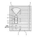
本実施形態に係る車線区画線検出装置13は、車両(走行体)が車線変更を行ったか否かを検出する装置であり、車両10に備えられる。図1は、走行路3を走行する車両10を示す概略図である。走行路3には、車線を区分けする車線区分線2が設けられている。車両10は、ウィンカ4と、カメラ1とを備えている。カメラ1は、車両10の進行方向とは反対側に向かって、走行路3を撮像する。撮像された画像は、車線区画線検出装置13に通知される。車線区画線検出装置13は、撮像された画像に基づいて車線変更が行われたか否かを検出する。車線区画線検出装置13による検出結果は、ウィンカ4の制御や、図示しないカーナビゲーションシステムに用いられる。 The lane
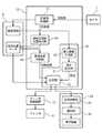
図2は、車線区画線検出装置13の構成を示すブロック図である。車線区画線検出装置13は、CPU5、RAM(Random access memory)、記憶部8、及び入出力インタフェース9を有するコンピュータにより実現される。RAMには、車線区画線検出プログラム6が格納されている。車線区画線検出プログラム6は、例えばCD−ROMなどの記憶メディアから、予めRAM6にインストールされている。車線区画線検出装置13は、車線区画線検出プログラム6がCPU5によって実行されることにより、その機能を実現する。入出力インタフェース9は、カメラ1、カーナビゲーション装置24、及びウィンカ制御装置12に接続されている。車線区画線検出装置13は、入出力インタフェース9を介して、カメラ1、カーナビゲーション装置24、及びウィンカ制御装置12との間の通信を行う。記憶部8は、ハードディスクやROM(Read Only Memory)に例示される。記憶部8には、車線区画線検出プログラム6により使用される各種データが格納される。 FIG. 2 is a block diagram illustrating a configuration of the lane
図3は、車線区画線検出装置13の機能構成を示す機能ブロック図である。車線区画線検出装置13は、原画像取得部14と、車線区画線位置検出部15と、車線変更判断部16と、検定部19とを備えている。検定部19は、第2画像生成部18と、傾き算出部21と、比較部23とを備えている。 FIG. 3 is a functional block diagram showing a functional configuration of the
記憶部8には、原画像群と、相対位置データとが、それぞれ時刻と対応付けられて格納されている。 The
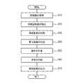
図4は、車線区画線検出装置13の動作方法を示すフローチャートである。 FIG. 4 is a flowchart showing an operation method of the
ステップS10;原画像の取得
原画像取得部14は、カメラ1により撮像されて得られた画像を、原画像28として取得する。図5は、原画像28を示す概念図である。原画像28中には、車両10から離れた領域が写された遠方領域と、車両10に近い領域が写された近傍領域とが含まれている。原画像取得部14は、所定の時間間隔で、原画像を取得する。原画像取得部14は、取得した原画像を、取得した時刻と対応付けて、記憶部8に格納する。これにより、記憶部8には、複数の原画像(原画像群)が、時刻と対応付けられて格納される。Step S <b> 10: Acquisition of Original Image The original
ステップS20;車線区画線の検出
現在時刻t0において原画像が取得されたとする。時刻t0における原画像が、以下、第1画像と記載される。車線区画線位置検出部15は、第1画像に基づいて、車線区画線2の車両10からの相対位置を検出する。車線区画線位置検出部15は、検出した相対位置に現在時刻t0を対応付け、相対位置データとして記憶部8に格納する。このような処理を所定の時間間隔で行うことにより、記憶部8には、複数の時刻のそれぞれについて、相対位置データが格納されることになる。Step S20: Detection of Lane Lanes Assume that an original image is acquired at the current time t0. The original image at time t0 is hereinafter referred to as a first image. The lane
ステップS30;車線区画線を越えたか否かの判断
車線変更判断部16は、相対位置データに基づいて、時刻t0までの相対位置を時系列的に追跡し、車線変更が行われたか否かを判断する。車線変更判断部16は、車線変更が行われたと判断した場合、その旨を判断結果として検定部19に通知する。Step S30: Judgment whether or not the vehicle has crossed the lane line The lane
ステップS30における車線変更が行われたか否かの判断は、時刻t0における相対位置が正しく検出されていることが前提となる。そこで、以下のステップS40以降の処理により、相対位置が正しく検出されているか否かが検定され、車線変更の判断結果が検定される。 The determination as to whether or not a lane change has been made in step S30 is based on the assumption that the relative position at time t0 has been correctly detected. Therefore, it is verified whether or not the relative position is correctly detected by the processing after step S40, and the determination result of the lane change is verified.
ステップS40;第2画像の生成
第2画像生成部18が、第1画像の部分画像に基づいて、第2画像を生成する。第2画像は、原画像の撮像方向とは異なる視点で走行路3を見たときの画像である。具体的には、第2画像は、原画像28に撮影されている風景を、実世界で鉛直方向下向きの視線で見た場合の画像である。第2画像は、現在時刻t0に取得された第1画像の部分画像と、過去に取得された原画像の部分画像とに基づいて得られる。図6は、本ステップにおける動作を示す概念図である。本ステップの動作について以下に詳述する。Step S40; Generation of Second Image The second
図6に示されるように、現在時刻t0において原画像28(t0)(第1画像)が取得されたとする。また、現在時刻t0よりも過去の時刻t1に、原画像28(t1)が取得されたとする。また、時刻t1において、原画像28(t1)に基づいて、第2画像27(t1)が生成されていたとする。 As shown in FIG. 6, it is assumed that the original image 28 (t0) (first image) is acquired at the current time t0. Further, it is assumed that the original image 28 (t1) is acquired at a time t1 that is past the current time t0. Further, it is assumed that the second image 27 (t1) is generated based on the original image 28 (t1) at time t1.
第2画像生成部18は、前時刻t1で生成された第2画像27(t1)の各画素を、車両10の移動距離に対応する量だけ、遠方方向に移動させ、第2画像27(t1)*を生成する。第2画像27(t1)*の車両近傍領域は、ブランクになる。The second
次に、第2画像生成部18は、第1画像28(t0)の近傍領域を、鉛直方向下向きの視線で見た場合の画像(すなわち鳥瞰画像)に変換し、第2画像27(t1)*のブランク部分に付加する。これにより、時刻t0における第2画像27(t0)が生成される。Next, the second
上述の処理は、原画像28が取得されるたびに実行される。すなわち、時刻tにて原画像28(t)が取得されるたびに、第2画像27(t)が生成されることになる。従って、時刻t1における第2画像27(t1)も、時刻t1以前に取得された原画像28の部分画像に基づいて生成された画像である。すなわち、第2画像27(t0)は、第1画像の部分画像と、時刻t0以前に取得された原画像28の部分画像とが、画像として接続されたものであるといえる。 The above-described processing is executed every time the
このようにして得られた第2画像27(t0)は、原画像28における近傍領域だけを含み、遠方領域を含んでいない。原画像28中において、遠方領域は、近傍領域よりも、ノイズが含まれている可能性が高い。従って、第2画像27では、遠方領域に起因するノイズが排除されている。 The second image 27 (t0) obtained in this way includes only the vicinity region in the
尚、第2画像27としては、原画像もしくは原画像の代わりに原画像から生成した(合成でない)鳥瞰画像、もしくはこれらにフィルタ等の処理を施した処理画像を用いることも可能である。また、第2画像27としては、画像27(t0)に対して更にフィルタ処理などが施された画像が用いられてもよい。 As the
第2画像生成部18は、生成した第2画像27を検定部19へ通知する。 The second
続いて、ステップS50以降の処理について説明する。図7は、ステップS50〜70における動作を説明する為の概念図である。 Next, processing after step S50 will be described. FIG. 7 is a conceptual diagram for explaining the operation in steps S50 to S70.
ステップS50;傾きの算出
時刻t2から時刻t0にかけて、車両10が車線変更を行ったとする。このとき、図7(a)に示されるように、時刻t2において原画像28(t2)が、時刻t1において原画像28(t1)が、時刻t0において第1画像28(t0)が、それぞれ生成される。車線変更が行われている場合、各原画像28(t2〜t0)において、車線区画線2の車両10に対する相対位置は移動する。車両10の走行速度が適当な速度であれば、図7(b)に示されるように、第2画像27(t0)内では、車線区画線2が斜めに延びるように示される。ステップS60では、傾き算出部21が、この車線区画線2の傾きを算出する。算出された傾きは、比較部23に通知される。Step S50; Calculation of Inclination Assume that the
ステップS60;矛盾があるか否かの判断
ステップS50で算出された傾きは、時刻と車線区画線2の相対位置との関係に対応するはずである。従って、比較部23は、相対位置データを参照して、算出された傾きが相対位置データと矛盾しているか否かを判定する。Step S60: Determination of whether or not there is a contradiction The inclination calculated in Step S50 should correspond to the relationship between the time and the relative position of the lane marking 2. Therefore, the
ステップS70;比較
ステップS60にて、矛盾がなければ、車線区画線位置検出部15における検出結果は、正しいと考えられる。従って、車線変更判断部16における判断結果も、正しいと考えられる。車線変更判断部16が車線変更が行われたと判断した場合であれば、比較部23は、その判断結果が正しいものであると検定する。すなわち、車線変更が行われた旨を出力する。一方、ステップS60にて矛盾があった場合には、車線区画線位置検出部15における検出結果は、誤りであると考えられる。そのため、比較部23は、車線変更判断部16における判断結果を、誤りであると検定する。比較部23は、仮に車線変更判断部16が車線変更が行われたと判断した場合であっても、車線変更は行われていないと判断する。Step S70: Comparison If there is no contradiction in step S60, the detection result in the lane marking
比較部23は、車線変更が行われたと判断した場合には、その旨をウィンカ制御装置12、及びカーナビゲーション装置24に通知する。 When the
ウィンカ制御装置12は、ウィンカ4を制御する。例えば、車線変更開始時には、通常、ウィンカ4が点滅させられる。このような場合に、ウィンカ制御装置12は、車線変更が行われた(終了した)旨の通知に応じて、ウィンカ4を消灯する。 The
カーナビゲーション装置24は、位置把握部25と、通知部26と、表示装置11(例えばディスプレイ)とを備えている。カーナビゲーション装置24では、車線変更が行われた旨が通知されると、位置把握部25が車両10の現在位置を把握する。そして、通知部26が、把握した現在位置に基づいて、表示装置11に現在位置を表示させ、ドライバーに現在位置を通知する。 The
以上説明したように、本実施形態によれば、検定部19が、第2画像27に基づいて、車線区画線位置検出部15で検出された相対位置が正しい位置であるか否かを検定する。第2画像28は、ノイズが含まれ易い遠方領域を含んでいない。従って、車線区画線位置検出部15による検出結果が遠方領域のノイズによって影響を受けていたとしても、検定部9によってそのノイズの影響を排除することができる。ノイズが存在する場合でも、正確に車線区画線2の相対位置を検出することができ、車線変更が行われたか否かを正確に判断することができる。 As described above, according to the present embodiment, the
また、本実施形態では、原画像28とは視点が異なる第2画像27に基づいて、検定が行われる。原画像28と第2画像27とでは、その性質が異なっているため、それぞれの画像において出現するノイズに起因した誤検出を抑制することができる。この点について、以下に詳述する。 In the present embodiment, the test is performed based on the
遠方領域に起因するノイズを削除する観点からは、第2画像27だけを利用して、車線区画線2の位置を検出すればよいと考えられる。しかし、第2画像27だけを利用した場合には、別の観点からノイズの影響を受けてしまい易くなることがある。例えば、図8(a)に示されるように、原画像28中における手前部分(近傍領域)に、雨滴36等が写っていたとする。このような雨滴等は、原画像28の同一位置に留まりやすい。その結果、第2画像27中においては、図8(b)に示されるように、雨滴36部分が、車線区画線2のように直線状に写ってしまいやすい。そのため、第2画像27だけを利用して車線区画線2の位置を検出した場合には、このような雨滴36等がノイズとなり、誤検出が発生しやすい。これに対して、雨滴36等によるノイズは、原画像28中では部分的なノイズであり、車線区画線2とは容易に区別される。 From the viewpoint of eliminating noise caused by the far region, it is considered that only the
すなわち、本実施形態によれば、撮像方向とは異なる方向から走行路3を見たときの画像(第2画像)を用いることにより、原画像及び第2画像のそれぞれの画像に由来する誤検出の原因を相殺することができる。その結果、ノイズが存在する場合でも、正確に車線変更が行われたか否かを検出することができる。 That is, according to the present embodiment, by using an image (second image) when the traveling
(実施例)
次に、本発明をより詳細に説明する為に、実施例について説明する。(Example)
Next, in order to describe the present invention in more detail, examples will be described.
実施の形態にて説明したように、本実施例に係る車両10には、後部に、進行方向とは逆方向を向いたカメラ1が備えられているものとする(図1参照)。本実施例に係る車線区画線検出装置13は、車線区画線2が車両10前方を相対的に横方向に通過する事象、すなわち、車両10が車線区画線2を跨ぐ事象を検出する装置である。 As described in the embodiment, it is assumed that the
本実施例に係る車両検出装置13の構成は、概略的には、実施形態に係る車両検出装置13(図3参照)と同様である。但し、本実施例では、各構成要素を、より具体的に説明する。 The configuration of the
まず、車線区画線位置検出部15及び車線変更部16の構成、動作について詳述する。 First, the configuration and operation of the lane line
図9は、車線区画線位置検出部15を具体的に示す機能構成図である。車線区画線位置検出部15は、原画像2値化部15−1と、Hough変換部15ー2と、左右自車車線区画線選択部15−3とを含んでいる。 FIG. 9 is a functional configuration diagram specifically illustrating the lane line
図10は、車線区画線位置検出部15及び車線変更判断部16における動作を詳細に示すフローチャートである。すなわち、ステップS20及びステップS30の動作を詳細に示すフローチャートである。 FIG. 10 is a flowchart showing in detail operations in the lane line
ステップS21;原画像の取得
時刻tにおいて、車線区画線位置検出部15が、処理対象の原画像28(t)を取得したとする。Step S21: Acquisition of Original Image It is assumed that the lane line
ステップS22;2値化
原画像2値化部15−1が、原画像28(t)を2値化し、原画像28(t)に含まれる各画素を、前景と背景とに分類する。例えば、原画像28(t)に含まれる各画素の階調数が256であったとする。この場合、原画像2値化部15−1は、各画素の輝度値を求め、輝度値が200以上である画素を前景に分類し、それ以外の画素を背景に分類する。Step S22: Binarization The original image binarization unit 15-1 binarizes the original image 28 (t) and classifies each pixel included in the original image 28 (t) into a foreground and a background. For example, it is assumed that the number of gradations of each pixel included in the original image 28 (t) is 256. In this case, the original image binarization unit 15-1 obtains a luminance value of each pixel, classifies pixels having a luminance value of 200 or more as the foreground, and classifies other pixels as the background.
ステップS23;Hough変換
次に、Hough変換部15−2が、前景の画素を特徴点としてHough変換を行い、直線群を検出する。Step S23: Hough Conversion Next, the Hough conversion unit 15-2 performs Hough conversion using the foreground pixels as feature points to detect a straight line group.
ステップS24;車線区画線の識別
次に、左右車線区画線選択部15−3が、検出された直線群に基づいて、車両10に対して左右の車線区画線2を識別する。例えば、左右自車車線区画線選択部15−3はHough変換部15−2により検出された直線群のうち、Hough時における投票値が多い直線を、左右の車両区画線2として識別する。又は、前時刻の左右の車線区画線2に最も近い直線を、左右の車両区画線2として識別する。そして、識別した車両区画線2の位置を、相対位置データとして、時刻tと対応付けて記憶部8に格納する。Step S24: Identification of Lane Lanes Next, the left and right lane markings selection unit 15-3 identifies the left and
車線区画線位置検出部15は、以上のステップS21〜24までの処理を、原画像取得部14によって原画像が取得されるたびに行う。 The lane line
尚、車線区画線位置検出部15の具体的構成は、上述の構成に限定されるものではない。車線区画線位置検出部15は、左右の車線区画線2らしい高輝度の線分又は直線を検出することができるように構成されていればよい。 Note that the specific configuration of the lane line
ステップS30;車線区画線を跨いだか否かの判断
現在時刻t0における処理に着目する。現在時刻t0において、車線変更判断部16は、車両10が左右どちらかの車線区画線2を跨いだか否かを判断する。具体的には、車線変更判断部16は、相対位置データを参照し、左右の車線区画線2の時刻t0までの相対位置を、時系列に把握する。車線変更判断部16は、時刻t0において、左右の車線区画線2のうちのいずれかが車両10の正面中央を含む所定の範囲(例えば、車両正面中央を中心とした±70cmの範囲)を超えた場合に、車両10が車線区画線2を跨いだと判断する。Step S30: Determination of whether or not the vehicle has crossed a lane line Pay attention to the processing at the current time t0. At the current time t0, the lane
続いて、第2画像生成部18及び傾き算出部21の構成及び動作を詳述する。 Next, the configuration and operation of the second
図11は、第2画像生成部18を具体的に示す機能構成図である。第2画像生成部18は、画素移動部18−1と、鳥瞰化部18−2と、領域付加部18−3とを含んでいる。 FIG. 11 is a functional configuration diagram specifically illustrating the second
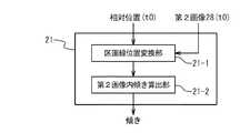
図12は、傾き算出部21を具体的に示す機能構成図である。傾き算出部21は、区画線位置変換部21−1と、第2画像内傾き算出部21−2とを含んでいる。 FIG. 12 is a functional configuration diagram specifically illustrating the
図13は、第2画像生成部18及び傾き算出部21の動作を示すフローチャートである。すなわち、ステップS40〜ステップS50の動作を示すフローチャートである。 FIG. 13 is a flowchart showing the operations of the second
ステップS41;画素の移動
時刻t0における処理に着目する。画素移動部18−1は、図6で示したように、時刻t0よりも過去の時刻t1に得られた第2画像27(t1)の各画素を、車両10の移動量に応じて、遠方に移動させる。例えば、第2画像27(t1)の最下部(車両の近傍方向端部)が、カメラ1の先端から1m離れた位置に対応するものとする。また、一つの画素が、道路面の縦5cm、横5cmに対応するものとする。また、車両10の前時刻t1からの移動量が、50cmであったとする。このような場合には、画素移動部18−1は、第2画像27(t1)中の各画素を、遠方方向側に10pixel移動させる。Step S41: Pixel Movement Attention is paid to the processing at time t0. As illustrated in FIG. 6, the pixel moving unit 18-1 moves each pixel of the second image 27 (t <b> 1) obtained at time t <b> 1 past the time t <b> 0 according to the amount of movement of the
ステップS42;鳥瞰画像化
鳥瞰化部18−2は、第1画像28(t0)の近傍領域を鳥瞰画像化する。この際、その近傍領域の範囲は、実世界における車両10の移動量に対応する範囲でなければならない。Step S42: Bird's-eye view imaging The bird's-eye view unit 18-2 converts the vicinity region of the first image 28 (t0) into a bird's-eye view image. At this time, the range of the vicinity region must be a range corresponding to the movement amount of the
以下に、鳥瞰画像化について詳述する。図14は、鳥瞰化部18−2の動作を説明する為の説明図である。 Hereinafter, the bird's-eye imaging will be described in detail. FIG. 14 is an explanatory diagram for explaining the operation of the bird's-eye view unit 18-2.
図14に示されるように、鳥瞰化部18−2は、カメラ1の撮像座標系を定める。本実施例においては、撮像の際の実世界から原画像への変換は、透視変換であるものとする。また、レンズ等の歪み等による他の変換の要因はないものとする。図14において、実世界の座標系がXYZで表され、原画像座標系がxyと表される。ここで、X軸とx軸、Y軸とy軸はそれぞれ平行である。また、透視変換における焦点距離が、fとして表される。また、道路面32は、Y軸に対して垂直な平面をなすものとする。実世界座標系の原点から道路面32までの距離が、Hとして表される。この場合、道路面32上の点(Xi、H、Xi)に対応する原画像内の座標(xi、yi)は、次式(1)により表現される。 As shown in FIG. 14, the bird's-eye view unit 18-2 determines the imaging coordinate system of the

鳥瞰画像は、道路面32を実世界で鉛直方向下向きの視線で見た場合の画像である。すなわち、道路面32上の実世界座標を、適当な間隔(例えば縦5cm、横5cm)により、量子化したものである。従って、部分画像を変換画像へ変換するために、鳥瞰化部18−1は、上式(1)により、変換画像要素内の各画素が第1画像内のどの画素に対応しているかを求める。そして、鳥瞰化部18−1は、変換画像要素内の各画素の輝度を、対応する第1画像内の画素の輝度に設定する。なお、カメラの撮像座標系において、透視変換以外の変換要因、例えばレンズの歪み等が存在する場合は、式(1)の代わりに、変換要因を考慮した変換式を用いればよい。 The bird's-eye view image is an image when the
ステップS43;ブランク部分に付加
領域付加部18−3は、鳥瞰画像を、画素が移動された第2画像27(t1)*のブランク部分に、付加する。これにより、時刻t0における第2画像27(t0)が得られる。Step S43: Addition to Blank Part The area addition unit 18-3 adds the bird's-eye view image to the blank part of the second image 27 (t1)* in which the pixels are moved. Thereby, the second image 27 (t0) at time t0 is obtained.
続いて、傾き算出部21の動作について説明する。 Next, the operation of the
ステップS51;車線区画線の位置の変換
前記区画線位置変換部21−1は、相対位置データを参照し、原画像28(t0)に基づいて得られた車線区画線2の位置(時刻t0の相対位置)を、例えば式(1)に基づき、第2画像27(t0)内における位置に変換する。Step S51: Conversion of Lane Lane Line Position The lane line position converter 21-1 refers to the relative position data, and determines the position of the lane line 2 (at time t0) obtained based on the original image 28 (t0). Relative position) is converted into a position in the second image 27 (t0) based on, for example, Expression (1).
ステップS52;車線区画線の像の角度の算出
第2画像内傾き算出部21−2は、第2画像27(t0)内での車線区画線2の傾きを算出する。以下に、第2画像内傾き算出部21−2の動作について詳述する。図15は、以下に、第2画像内傾き算出部21−2の動作を説明するための説明図である。Step S52: Calculation of the angle of the image of the lane line The second image inclination calculation unit 21-2 calculates the inclination of the
ステップS51で得られた車線区画線2の第2画像27(t0)内における位置が、原画像内車線区画線位置33と定義される。第2画像内傾き算出部21−2は、原画像内車線区画線位置33を、第2画像27(t0)における手前切片(車両近傍側端部)に設定する。第2画像内傾き算出部21−1は、位置33から延びるように、車両区画線2を設定する。第2画像内傾き算出部21−1は、第2画像27内に設定される中心軸線(車両近傍側から遠方側へ延びる線)と、設定した車線区画線2とが成す角度θを求める。ここで、角度θは、予め設定される角度範囲35内で設定される。このようにして、第2画像27(t0)内において、車線区画線2の像の位置が表現される。車線区画線2は、例えば、車線区画線2における画素値の和が最大となるように、設定される。具体的な例を挙げれば、角度範囲35が、中心軸線から±30度の範囲に設定されたとする。第2画像内傾き算出部21−1は、その角度範囲35内で、1度刻みで、車線区画線2の候補を設定する。そして、車線区画線2の候補又は車線区画線2の候補の周辺(例示;車線区画線2の候補を中心とした左右20cmの範囲)における画素値の和を、計算する。そして、設定した車線区画線2の候補のうちで、画素値の和が最大となるような線を、車線区画線2として決定し、角度θを決定する。第2画像内傾き算出部21−1は、決定した角度θを、時刻t0における傾きとして出力する。 The position in the second image 27 (t0) of the
第2画像内傾き算出部21−1は、上述の処理を、原画像28が取得されるたびに行う。尚、角度θの決定にあたって用いられる評価値としては、必ずしも画素値の和が用いられる必要はない。その評価値としては、車線区画線らしさが表現された値が用いられればよい。 The second image inclination calculation unit 21-1 performs the above-described processing every time the
続いて、比較部23の構成及び動作を詳述する。図16は、比較部23の構成を詳細に示す機能構成図である。比較部23は、傾き変換部23−1と、推定移動量検定部23−2とを備えている。また、図17は、比較部23の動作を示すフローチャートであり、ステップS70における動作を示すフローチャートである。 Next, the configuration and operation of the
ステップS61;推定移動量Dの計算
比較部23では、傾き(角度θ)に基づいて、車線区画線2の横方向への推定移動量Dが計算される。Step S61: Calculation of Estimated Travel Distance D The
現在時刻t0における処理について着目する。傾き変換部23−1は、前時間t1から現時刻t0までの単位期間(時刻t1〜t0)における車両10の走行距離をRtとして取得し、単位期間(時刻t1〜t0)における車線区画線2の相対位置の横方向への移動量Dtを、角度θを用いて、下記式(2)により計算する。Rtは、例えば、車両10に備えられた走行距離測定器から得られる。 Attention is paid to the processing at the current time t0. The slope conversion unit 23-1 acquires the travel distance of the
また、傾き変換部23−1は、相対位置データを参照し、車両区画線2の相対位置が、車両10の正面中央を含む所定の範囲(以下、第1範囲と記載する)に位置している期間を、第1期間として把握する。第1範囲は、例えば、車両10の正面中央から±70cmの範囲であり、予め記憶部8などに設定されている。次に、傾き変換部23−1は、第1期間における移動量Dtの総和を、推定移動量Dとして計算する。 Further, the inclination conversion unit 23-1 refers to the relative position data, and the relative position of the lane marking 2 is located in a predetermined range including the front center of the vehicle 10 (hereinafter referred to as a first range). For the first period. The first range is, for example, a range of ± 70 cm from the front center of the
なお、推定移動量Dの計算方法は上述の方法に限定されるものではない。例えば、角度θに代えて、第1期間における角度θの平均値又は中央値が用いられてもよい。また、角度θに代えて、何らかの方法による角度θの推定値θaが用いられてもよい。また、傾き変換部23−1は、車線区画線2が第1範囲を通過した段階で、第1期間における車両10の走行距離Rを計算し、下記式(3)に従って推定移動量Dを求めてもよい。 Note that the method of calculating the estimated movement amount D is not limited to the above-described method. For example, instead of the angle θ, an average value or a median value of the angles θ in the first period may be used. Instead of the angle θ, an estimated value θa of the angle θ by some method may be used. In addition, the inclination conversion unit 23-1 calculates the travel distance R of the
ステップS62;推定移動量の判定
推定移動量検定部23−2は、推定移動量Dを第1範囲の長さ(例えば140cm)と比較する。ステップS20にて車線区画線2の相対位置が正しく検出されていれば、推定移動量Dは第1範囲の長さに一致するはずである。従って、推定移動量検定部23−2は、推定移動量Dと第1範囲の長さとの差を求め、その差が所定の値(例えば、第1範囲の長さの20%)以内である場合には、車線区画線2の相対位置が正しく検出されていると判断する。そして、車線変更判断部16の判断結果は正しいと判断する。一方、推定移動量Dと第1範囲の長さとの差が所定の値よりも大きい場合には、車線区画線2の相対位置が誤って検出されたと判断する。この場合には、車線変更判断部16の判断結果が間違っていると判断する。Step S62: Determination of Estimated Movement Amount The estimated movement amount testing unit 23-2 compares the estimated movement amount D with the length of the first range (for example, 140 cm). If the relative position of the lane marking 2 is correctly detected in step S20, the estimated movement amount D should match the length of the first range. Therefore, the estimated movement amount test unit 23-2 obtains a difference between the estimated movement amount D and the length of the first range, and the difference is within a predetermined value (for example, 20% of the length of the first range). In this case, it is determined that the relative position of the lane marking 2 is correctly detected. And the judgment result of the lane
ステップS70;検定結果の出力
その後、比較部23は、ステップS62の結果に基づいて、車線変更判断部16における判断が正しいと判断した場合にだけ、車線変更が行われた旨を出力する。Step S70: Output of Test Result Thereafter, the
以上、本発明の実施の形態、及び実施例について説明した。ただし、上述の実施の形態及び実施例は、本発明の趣旨を逸脱しない範囲内において、様々に変更可能である。例えば、上述の実施形態、及び実施例では、検出された車線区画線2の相対位置が、車線変更が行われたか否かの判断に用いられる場合について説明した。但し、本発明は、車線変更が行われたか否かの判断を行う装置に限定されるものではない。たとえば、検出された車線区画線2の相対位置が、車線区画線2が車両から相対的に移動したことを検出するために用いられてもよい。 The embodiment and the example of the present invention have been described above. However, the above-described embodiments and examples can be variously modified without departing from the spirit of the present invention. For example, in the above-described embodiment and examples, the case has been described in which the detected relative position of the lane marking 2 is used to determine whether or not a lane change has been performed. However, the present invention is not limited to an apparatus that determines whether or not a lane change has been performed. For example, the detected relative position of the
1 カメラ
2 車線区画線
3 走行路
4 ウィンカ
5 CPU
6 車線変更検出プログラム
7 記憶メディア
8 記憶部
9 入出力インタフェース
10 走行体(車両)
11 表示装置
12 ウィンカ制御装置
13 車線変更検出装置
14 原画像取得部
15 車線区画線位置検出部
15−1 2値化部
15−2 Hough変換部
15−3 左右自車車線区画線選択部
16 車線変更判断部
18 第2画像生成部
18−1 画素移動部
18−2 鳥瞰化部
18−3 領域付加部
19 検定部
20 第1移動量算出部
21 傾き算出部
21−1 区画線位置変換部
21−2 第2画像内傾き算出部
23 比較部
23−1 傾き変換部
23−2 推定移動量検定部
24 カーナビゲーション装置
25 位置把握部
26 通知部
27 第2画像
28 原画像
28(t0) 第1画像
29 近傍画像要素
30 画像面
31 道路面の世界座標原点からの距離
32 道路面
33 原画像内車線区画線位置
34 画像内角度
35 区画線角度範囲
36 水滴1
6 Lane change detection program 7
DESCRIPTION OF SYMBOLS 11
Claims (7)
Translated fromJapanese前記原画像に基づいて、前記走行路に含まれる車線区画線の前記走行体からの相対位置を検出する車線区画線位置検出手段と、
前記車線区画線位置検出手段により検出された前記相対位置に基づいて、前記走行体が前記車線区画線を超えたか否かを判断する車線変更判断手段と、
時刻t0に取得された前記原画像である第1画像のうちの前記走行体に近い領域が写された近傍領域を、前記原画像における撮像方向とは異なる第1方向から前記走行路を見たときの画像に変換して第1変換画像を生成し、前記時刻t0よりも過去における前記原画像である過去画像のうちの前記走行体に近い領域が写された近傍領域を、前記第1方向から見たときの画像に変換して過去変換画像を生成し、前記第1変換画像と前記過去変換画像を時刻順に画像として接続することにより第2画像を生成し、前記第2画像に基づいて前記車線変更判断手段の判断結果が正しいか否かを検定する、検定手段と、
を具備する
車線区画線検出装置。Original image acquisition means for acquiring an original image obtained by imaging the travel path from a traveling body traveling on the travel path;
Lane marking position detecting means for detecting a relative position of the lane marking included in the travel path from the traveling body based on the original image;
Lane change determination means for determining whether or not the traveling body has exceeded the lane line based on the relative position detected by the lane line position detection means;
Thevicinity area where the area close to the traveling body in the first image which is the original image acquired at time t0 is viewed from the first direction different from the imaging direction in the original image. A first converted image is generated by converting the image to the time image,and a neighboring region in which a region close to the traveling body is copied in the past image that is the original image in the past from the time t0 isdefined in the first direction. A past converted image is generated by converting into an image when viewed from the above, and a second image is generated by connecting the first converted image and the past converted image as images in order of time, and based on the second image Testing means for testing whether the judgment result of the lane change judging means is correct; and
A lane marking detection device comprising:
前記検定手段は、
前記第2画像内に示される前記車線区画線の傾きを算出する傾き算出手段と、
前記傾きに基づいて、所定期間における前記車線区画線の相対位置の移動量を、推定移動量として算出する、推定移動量算出手段と、
前記推定移動量に基づいて、車線区画線位置検出手段における検出結果を検定する、比較手段とを備える
車線区画線検出装置。A lane marking detection device according to claim 1,
The test means is
An inclination calculating means for calculating an inclination of the lane marking shown in the second image;
An estimated movement amount calculating means for calculating, as an estimated movement amount, a movement amount of the relative position of the lane line in a predetermined period based on the inclination;
A lane marking detection device comprising comparison means for verifying a detection result in the lane marking position detection means based on the estimated movement amount.
前記第1方向は、前記走行路を鉛直上方向から鉛直下方向に見たときの方向である
車線区画線検出装置。A lane marking detection device according to claim 1 or 2,
The first direction is a lane marking detection device that is a direction when the traveling road is viewed from vertically upward to vertically downward.
前記検定手段による検定結果に基づいて、前記走行体の位置を把握する位置把握手段と、
前記位置把握手段により把握された位置をユーザに通知する通知手段と、
を具備する
カーナビゲーションシステム。A lane marking detection device according to any one of claims 1 to 3,
Position grasping means for grasping the position of the traveling body based on the test result by the test means;
Notification means for notifying the user of the position grasped by the position grasping means;
A car navigation system comprising:
前記検定手段による検定結果に基づいて、前記走行体に設けられたウィンカを制御するウィンカ制御手段と、
を具備する
ウィンカシステム。A lane marking detection device according to any one of claims 1 to 3,
A winker control means for controlling a winker provided in the traveling body, based on a test result by the test means,
A winker system.
前記原画像に基づいて、前記走行路に含まれる車線区画線の前記走行体からの相対位置を検出し、
前記検出された前記相対位置に基づいて、前記走行体が前記車線区画線を超えたか否かを判断し、
時刻t0に取得された前記原画像である第1画像のうちの前記走行体に近い領域が写された近傍領域を、前記原画像における撮像方向とは異なる第1方向から前記走行路を見たときの画像に変換して第1変換画像を生成し、前記時刻t0よりも過去における前記原画像である過去画像のうちの前記走行体に近い領域が写された近傍領域を、前記第1方向から見たときの画像に変換して過去変換画像を生成し、前記第1変換画像と前記過去変換画像とを時刻順に画像として接続することにより第2画像を生成し、前記第2画像に基づいて前記走行体が前記車線区画線を超えたか否かの判断結果が正しいか否かを検定する
車線区画線検出方法。Obtain an original image obtained by imaging the traveling road from a traveling body traveling on the traveling road,
Based on the original image, detect the relative position of the lane marking included in the travel path from the traveling body,
Based on the detected relative position, it is determined whether the traveling body has exceeded the lane marking,
Thevicinity area where the area close to the traveling body in the first image which is the original image acquired at time t0 is viewed from the first direction different from the imaging direction in the original image. A first converted image is generated by converting the image to the time image,and a neighboring region in which a region close to the traveling body is copied in the past image that is the original image in the past from the time t0 isdefined in the first direction. A past converted image is generated by converting into an image when viewed from above, and a second image is generated by connecting the first converted image and the past converted image as images in order of time, and based on the second image A lane marking detection method for verifying whether or not the determination result of whether or not the traveling body exceeds the lane marking is correct.
前記原画像に基づいて、前記走行路に含まれる車線区画線の前記走行体からの相対位置を検出し、
前記検出された前記相対位置に基づいて、前記走行体が前記車線区画線を超えたか否かを判断し、
時刻t0に取得された前記原画像である第1画像のうちの前記走行体に近い領域が写された近傍領域を、前記原画像における撮像方向とは異なる第1方向から前記走行路を見たときの画像に変換して第1変換画像を生成し、前記時刻t0よりも過去における前記原画像である過去画像のうちの前記走行体に近い領域が写された近傍領域を、前記第1方向から見たときの画像に変換して過去変換画像を生成し、前記第1変換画像と前記過去変換画像とを時刻順に画像として接続することにより第2画像を生成し、前記第2画像に基づいて前記走行体が前記車線区画線を超えたか否かの判断結果が正しいか否かを検定する
車線区画線検出方法を、コンピュータに実行させるための、車線区画線検出プログラム。Obtain an original image obtained by imaging the traveling road from a traveling body traveling on the traveling road,
Based on the original image, detect the relative position of the lane marking included in the travel path from the traveling body,
Based on the detected relative position, it is determined whether the traveling body has exceeded the lane marking,
Thevicinity area where the area close to the traveling body in the first image which is the original image acquired at time t0 is viewed from the first direction different from the imaging direction in the original image. A first converted image is generated by converting the image to the time image,and a neighboring region in which a region close to the traveling body is copied in the past image that is the original image in the past from the time t0 isdefined in the first direction. A past converted image is generated by converting into an image when viewed from above, and a second image is generated by connecting the first converted image and the past converted image as images in order of time, and based on the second image A lane line detection program for causing a computer to execute a lane line detection method for verifying whether or not the determination result of whether or not the traveling body has exceeded the lane line is correct.
Priority Applications (3)
| Application Number | Priority Date | Filing Date | Title |
|---|---|---|---|
| JP2008271813AJP4656456B2 (en) | 2008-10-22 | 2008-10-22 | Lane marking device, lane marking detection method, and lane marking detection program |
| PCT/JP2009/067471WO2010047226A1 (en) | 2008-10-22 | 2009-10-07 | Lane line detection device, lane line detection method, and lane line detection program |
| US13/062,765US8594380B2 (en) | 2008-10-22 | 2009-10-07 | Lane marking detection apparatus, lane marking detection method, and lane marking detection program |
Applications Claiming Priority (1)
| Application Number | Priority Date | Filing Date | Title |
|---|---|---|---|
| JP2008271813AJP4656456B2 (en) | 2008-10-22 | 2008-10-22 | Lane marking device, lane marking detection method, and lane marking detection program |
Related Child Applications (1)
| Application Number | Title | Priority Date | Filing Date |
|---|---|---|---|
| JP2010207585ADivisionJP5062316B2 (en) | 2010-09-16 | 2010-09-16 | Lane marking device, lane marking detection method, and lane marking detection program |
Publications (2)
| Publication Number | Publication Date |
|---|---|
| JP2010102427A JP2010102427A (en) | 2010-05-06 |
| JP4656456B2true JP4656456B2 (en) | 2011-03-23 |
Family
ID=42119268
Family Applications (1)
| Application Number | Title | Priority Date | Filing Date |
|---|---|---|---|
| JP2008271813AActiveJP4656456B2 (en) | 2008-10-22 | 2008-10-22 | Lane marking device, lane marking detection method, and lane marking detection program |
Country Status (3)
| Country | Link |
|---|---|
| US (1) | US8594380B2 (en) |
| JP (1) | JP4656456B2 (en) |
| WO (1) | WO2010047226A1 (en) |
Families Citing this family (13)
| Publication number | Priority date | Publication date | Assignee | Title |
|---|---|---|---|---|
| JP5786941B2 (en)* | 2011-08-25 | 2015-09-30 | 日産自動車株式会社 | Autonomous driving control system for vehicles |
| JP6214995B2 (en)* | 2013-10-11 | 2017-10-18 | 株式会社東芝 | Parked vehicle detection device, vehicle management system, control method, and control program |
| US9677898B2 (en) | 2014-06-17 | 2017-06-13 | Think Ware Corporation | Electronic apparatus and control method thereof |
| KR102255432B1 (en)* | 2014-06-17 | 2021-05-24 | 팅크웨어(주) | Electronic apparatus and control method thereof |
| EP3098753A1 (en) | 2015-05-28 | 2016-11-30 | Tata Consultancy Services Limited | Lane detection |
| US10759432B2 (en)* | 2015-07-15 | 2020-09-01 | Honda Motor Co., Ltd. | Vehicle control apparatus, vehicle control method, and vehicle control program |
| FR3047589B1 (en)* | 2016-02-10 | 2018-02-02 | Peugeot Citroen Automobiles Sa | METHOD AND DEVICE FOR ESTIMATING THE LATERAL POSITION OF A VEHICLE IN A CIRCULATION PATH |
| CA3018663C (en)* | 2016-03-24 | 2019-04-30 | Nissan Motor Co., Ltd. | Travel lane detection method and travel lane detection device |
| CN109543493B (en)* | 2017-09-22 | 2020-11-20 | 杭州海康威视数字技术股份有限公司 | A lane line detection method, device and electronic device |
| CN112258841B (en)* | 2020-10-26 | 2022-08-02 | 大连大学 | Intelligent vehicle risk assessment method based on vehicle track prediction |
| US12330639B1 (en)* | 2021-07-21 | 2025-06-17 | Mobileye Vision Technologies, Ltd. | Identifying lane markings using a trained model |
| CN114299461A (en)* | 2021-12-06 | 2022-04-08 | 江苏航天大为科技股份有限公司 | Two-stage-based vehicle illegal lane change identification method |
| WO2023233515A1 (en)* | 2022-05-31 | 2023-12-07 | 三菱電機株式会社 | Object detection device, object detection method, and object detection program |
Family Cites Families (32)
| Publication number | Priority date | Publication date | Assignee | Title |
|---|---|---|---|---|
| JP2665738B2 (en)* | 1986-07-11 | 1997-10-22 | 株式会社小松製作所 | Guidance Method of Unmanned Mobile Machine by Point Tracking Method |
| JPH0778234A (en) | 1993-06-30 | 1995-03-20 | Nissan Motor Co Ltd | Road detection device |
| JP2798349B2 (en)* | 1993-11-08 | 1998-09-17 | 松下電器産業株式会社 | Vehicle position detection device |
| JP3390289B2 (en)* | 1995-06-16 | 2003-03-24 | 富士重工業株式会社 | Alarm device |
| US5835028A (en)* | 1997-05-05 | 1998-11-10 | Bender; Lee | Lane marker position sensor and alarm |
| JP2000011298A (en)* | 1998-06-22 | 2000-01-14 | Yazaki Corp | Rear side monitoring device for vehicles |
| JP3610852B2 (en)* | 1999-12-17 | 2005-01-19 | 三菱自動車工業株式会社 | Lane departure control device |
| JP2001289654A (en)* | 2000-04-11 | 2001-10-19 | Equos Research Co Ltd | NAVIGATION DEVICE, NAVIGATION DEVICE CONTROL METHOD, AND RECORDING MEDIUM RECORDING ITS PROGRAM |
| JP2002029347A (en) | 2000-07-17 | 2002-01-29 | Honda Motor Co Ltd | Vehicle lane marking detector |
| JP3651387B2 (en)* | 2000-11-22 | 2005-05-25 | 日産自動車株式会社 | White line detector |
| JP3736346B2 (en)* | 2000-12-26 | 2006-01-18 | 日産自動車株式会社 | Lane detection device |
| KR100391442B1 (en)* | 2000-12-27 | 2003-07-12 | 현대자동차주식회사 | Image processing method for preventing a vehicle from running off the line |
| KR20020094545A (en)* | 2001-06-12 | 2002-12-18 | 현대자동차주식회사 | A method for controlling a vehicle to be kept in a lane and a method thereof |
| JP2003044978A (en)* | 2001-07-27 | 2003-02-14 | Mitsubishi Motors Corp | Travel lane recognition device |
| ES2391556T3 (en)* | 2002-05-03 | 2012-11-27 | Donnelly Corporation | Object detection system for vehicles |
| US6930593B2 (en)* | 2003-02-24 | 2005-08-16 | Iteris, Inc. | Lane tracking system employing redundant image sensing devices |
| GB0305304D0 (en)* | 2003-03-07 | 2003-04-09 | Qinetiq Ltd | Scanning apparatus and method |
| JP4066869B2 (en)* | 2003-04-08 | 2008-03-26 | トヨタ自動車株式会社 | Image processing apparatus for vehicle |
| JP3979339B2 (en)* | 2003-05-12 | 2007-09-19 | 日産自動車株式会社 | Lane departure prevention device |
| US20050031169A1 (en)* | 2003-08-09 | 2005-02-10 | Alan Shulman | Birds eye view virtual imaging for real time composited wide field of view |
| JP3898709B2 (en)* | 2004-05-19 | 2007-03-28 | 本田技研工業株式会社 | Vehicle lane marking recognition device |
| JP2006069323A (en)* | 2004-09-01 | 2006-03-16 | Mazda Motor Corp | Lane deviation warning device for vehicle |
| JP2006069322A (en)* | 2004-09-01 | 2006-03-16 | Mazda Motor Corp | Lane deviation warning device for vehicle |
| JP4229051B2 (en)* | 2004-11-26 | 2009-02-25 | 日産自動車株式会社 | Driving intention estimation device, vehicle driving assistance device, and vehicle equipped with vehicle driving assistance device |
| US7050908B1 (en)* | 2005-03-22 | 2006-05-23 | Delphi Technologies, Inc. | Lane marker projection method for a motor vehicle vision system |
| JP4603421B2 (en)* | 2005-05-27 | 2010-12-22 | 本田技研工業株式会社 | Vehicle, image processing system, image processing method, and image processing program |
| JP2006012191A (en) | 2005-09-01 | 2006-01-12 | Honda Motor Co Ltd | Vehicle lane marking recognition device |
| JP2007114020A (en)* | 2005-10-19 | 2007-05-10 | Aisin Aw Co Ltd | Vehicle moving distance detecting method and device, and current vehicle position detecting method and device |
| JP2007241468A (en)* | 2006-03-06 | 2007-09-20 | Toyota Motor Corp | Lane change detection device |
| DE102006062061B4 (en)* | 2006-12-29 | 2010-06-10 | Fraunhofer-Gesellschaft zur Förderung der angewandten Forschung e.V. | Apparatus, method and computer program for determining a position based on a camera image from a camera |
| JP2008187564A (en)* | 2007-01-31 | 2008-08-14 | Sanyo Electric Co Ltd | Camera calibration apparatus and method, and vehicle |
| JP4861850B2 (en)* | 2007-02-13 | 2012-01-25 | アイシン・エィ・ダブリュ株式会社 | Lane determination device and lane determination method |
- 2008
- 2008-10-22JPJP2008271813Apatent/JP4656456B2/enactiveActive
- 2009
- 2009-10-07WOPCT/JP2009/067471patent/WO2010047226A1/enactiveApplication Filing
- 2009-10-07USUS13/062,765patent/US8594380B2/enactiveActive
Also Published As
| Publication number | Publication date |
|---|---|
| JP2010102427A (en) | 2010-05-06 |
| US8594380B2 (en) | 2013-11-26 |
| WO2010047226A1 (en) | 2010-04-29 |
| US20110164790A1 (en) | 2011-07-07 |
Similar Documents
| Publication | Publication Date | Title |
|---|---|---|
| JP4656456B2 (en) | Lane marking device, lane marking detection method, and lane marking detection program | |
| JP6246014B2 (en) | Exterior recognition system, vehicle, and camera dirt detection method | |
| CN104584076B (en) | Image processing device and image processing method | |
| JP6184877B2 (en) | Vehicle external recognition device | |
| KR100816377B1 (en) | Parking Lot Recognition Method and Apparatus Using Hough Transformation and Parking Assistance System Using the Same | |
| JP5401257B2 (en) | Far-infrared pedestrian detection device | |
| CN104870256A (en) | Vehicle control device | |
| JP2008299458A (en) | Vehicle monitoring apparatus and vehicle monitoring method | |
| WO2019021876A1 (en) | In-vehicle camera calibration device and method | |
| US10789727B2 (en) | Information processing apparatus and non-transitory recording medium storing thereon a computer program | |
| JP5062316B2 (en) | Lane marking device, lane marking detection method, and lane marking detection program | |
| JP2012252501A (en) | Traveling path recognition device and traveling path recognition program | |
| KR101637535B1 (en) | Apparatus and method for correcting distortion in top view image | |
| JP5012522B2 (en) | Roadside boundary surface detection device | |
| JP2018073275A (en) | Image recognition device | |
| JP2016162130A (en) | Device and method for detecting pedestrian crossing and computer for pedestrian crossing detection | |
| JP4765113B2 (en) | Vehicle periphery monitoring device, vehicle, vehicle periphery monitoring program, and vehicle periphery monitoring method | |
| JP4432730B2 (en) | Road marking detection device for vehicles | |
| JP2007018451A (en) | Road marking line detection device | |
| JP4847303B2 (en) | Obstacle detection method, obstacle detection program, and obstacle detection apparatus | |
| JP5487648B2 (en) | Moving object measuring system, moving object measuring apparatus, moving object measuring method and program | |
| KR20180070125A (en) | Autonomous Emergency Braking System And Method of Driving thereof | |
| JP2007272461A (en) | Motion estimation apparatus, method, and program | |
| JP4956841B2 (en) | VEHICLE IMAGE PROCESSING DEVICE, VEHICLE, AND VEHICLE IMAGE PROCESSING PROGRAM | |
| JP2019096031A (en) | Estimation program, estimation device, and estimation method |
Legal Events
| Date | Code | Title | Description |
|---|---|---|---|
| A02 | Decision of refusal | Free format text:JAPANESE INTERMEDIATE CODE: A02 Effective date:20100623 | |
| A521 | Request for written amendment filed | Free format text:JAPANESE INTERMEDIATE CODE: A523 Effective date:20100916 | |
| A911 | Transfer to examiner for re-examination before appeal (zenchi) | Free format text:JAPANESE INTERMEDIATE CODE: A911 Effective date:20100927 | |
| TRDD | Decision of grant or rejection written | ||
| A01 | Written decision to grant a patent or to grant a registration (utility model) | Free format text:JAPANESE INTERMEDIATE CODE: A01 Effective date:20101202 | |
| A01 | Written decision to grant a patent or to grant a registration (utility model) | Free format text:JAPANESE INTERMEDIATE CODE: A01 | |
| A61 | First payment of annual fees (during grant procedure) | Free format text:JAPANESE INTERMEDIATE CODE: A61 Effective date:20101215 | |
| FPAY | Renewal fee payment (event date is renewal date of database) | Free format text:PAYMENT UNTIL: 20140107 Year of fee payment:3 | |
| R150 | Certificate of patent or registration of utility model | Ref document number:4656456 Country of ref document:JP Free format text:JAPANESE INTERMEDIATE CODE: R150 Free format text:JAPANESE INTERMEDIATE CODE: R150 |