JP4656421B2 - Bus communication system - Google Patents
Bus communication systemDownload PDFInfo
- Publication number
- JP4656421B2 JP4656421B2JP2006052358AJP2006052358AJP4656421B2JP 4656421 B2JP4656421 B2JP 4656421B2JP 2006052358 AJP2006052358 AJP 2006052358AJP 2006052358 AJP2006052358 AJP 2006052358AJP 4656421 B2JP4656421 B2JP 4656421B2
- Authority
- JP
- Japan
- Prior art keywords
- identifier
- slave
- slave device
- failure
- signal
- Prior art date
- Legal status (The legal status is an assumption and is not a legal conclusion. Google has not performed a legal analysis and makes no representation as to the accuracy of the status listed.)
- Expired - Fee Related
Links
Images


Classifications
- H—ELECTRICITY
- H04—ELECTRIC COMMUNICATION TECHNIQUE
- H04L—TRANSMISSION OF DIGITAL INFORMATION, e.g. TELEGRAPHIC COMMUNICATION
- H04L12/00—Data switching networks
- H04L12/28—Data switching networks characterised by path configuration, e.g. LAN [Local Area Networks] or WAN [Wide Area Networks]
- H04L12/40—Bus networks
- H04L12/403—Bus networks with centralised control, e.g. polling
- H—ELECTRICITY
- H04—ELECTRIC COMMUNICATION TECHNIQUE
- H04L—TRANSMISSION OF DIGITAL INFORMATION, e.g. TELEGRAPHIC COMMUNICATION
- H04L12/00—Data switching networks
- H04L12/28—Data switching networks characterised by path configuration, e.g. LAN [Local Area Networks] or WAN [Wide Area Networks]
- H04L12/40—Bus networks
- H04L12/40169—Flexible bus arrangements
- H—ELECTRICITY
- H04—ELECTRIC COMMUNICATION TECHNIQUE
- H04L—TRANSMISSION OF DIGITAL INFORMATION, e.g. TELEGRAPHIC COMMUNICATION
- H04L12/00—Data switching networks
- H04L12/28—Data switching networks characterised by path configuration, e.g. LAN [Local Area Networks] or WAN [Wide Area Networks]
- H04L12/40—Bus networks
- H04L12/40006—Architecture of a communication node
- H04L12/40032—Details regarding a bus interface enhancer
- H—ELECTRICITY
- H04—ELECTRIC COMMUNICATION TECHNIQUE
- H04L—TRANSMISSION OF DIGITAL INFORMATION, e.g. TELEGRAPHIC COMMUNICATION
- H04L12/00—Data switching networks
- H04L12/28—Data switching networks characterised by path configuration, e.g. LAN [Local Area Networks] or WAN [Wide Area Networks]
- H04L12/40—Bus networks
- H04L2012/40267—Bus for use in transportation systems
- H04L2012/40273—Bus for use in transportation systems the transportation system being a vehicle
Landscapes
- Engineering & Computer Science (AREA)
- Computer Networks & Wireless Communication (AREA)
- Signal Processing (AREA)
- Small-Scale Networks (AREA)
Description
Translated fromJapanese本発明は、マスタ装置と複数のスレーブ装置とがデイジーチェーン接続されたバス通信システムに関するものである。 The present invention relates to a bus communication system in which a master device and a plurality of slave devices are daisy chain connected.
車両衝突時に乗員を保護する車両用乗員保護装置として、例えば特許文献1に開示されたものがある。特許文献1に開示されている車両用乗員保護装置は、制御装置と、通信バスを介してデイジーチェーン接続された複数の衝突検知用センサとを備えている。 As an occupant protection device for a vehicle that protects an occupant at the time of a vehicle collision, there is one disclosed in
ところで、同一の通信バスに接続される複数の衝突検知用センサは、互いに区別するために、固有の識別子を記憶している。ただし、複数の衝突検知用センサは、部品の共通化の要請から、車両搭載後に識別子を記憶させている。つまり、初期設定の際に、制御装置によって、それぞれの衝突検知用センサにそれぞれ固有の識別子を設定する。 By the way, a plurality of collision detection sensors connected to the same communication bus store unique identifiers in order to distinguish them from each other. However, the plurality of collision detection sensors store identifiers after being mounted on the vehicle in response to a request for common parts. That is, at the time of initial setting, a unique identifier is set for each collision detection sensor by the control device.
このような車両用乗員保護装置の衝突検知用センサ5〜7は、例えば、図3に示すような構成からなる。すなわち、それぞれの衝突検知用センサ5〜7は、制御装置2(図3において「エアバッグECU」と示す)との信号授受を行う通信回路5a、6a、7aと、前段側と後段側との通信の接続遮断を行うバススイッチ5b、6b、7bと、加速度センサ5c、6c、7cと、識別子を記憶するRAM5d、6d、7dとを備えている。 The
そして、初期設定において、制御装置2が、前段側から後段側の衝突検知用センサ5〜7に対して順次に識別子付与信号を出力することと、前段側から後段側の衝突検知用センサ5〜7のそれぞれのバススイッチ5b〜7bを順次に接続させることを交互に繰り返す。つまり、まず、制御装置2が当該制御装置2に直接接続されている第1番目の衝突検知用センサ5に対して第1の識別子付与信号を出力し、第1番目の衝突検知用センサ5は第1の識別子をRAM5dに記憶する。 Then, in the initial setting, the
続いて、第1番目の衝突検知用センサ5のバススイッチ5bをオンさせて、制御装置2と第2番目の衝突検知用センサ6とを接続させる。続いて、制御装置2が第2番目の衝突検知用センサ6に対して第2の識別子付与信号を出力し、第2番目の衝突検知用センサ6は第2の識別子をRAM6dに記憶する。続いて、第2番目の衝突検知用センサ6のバススイッチ6bをオンさせて、制御装置2と第3番目の衝突検知用センサ7とを接続させる。以降、後段側の衝突検知用センサ7に対して同様の処理を行う。このようにすることで、複数の衝突検知用センサ5〜7は、それぞれ固有の識別子を取得し、記憶している。
ここで、バススイッチ5b〜7bの故障判定は、制御装置2に予め記憶されている衝突検知用センサ5〜7の数と制御装置2によって設定された識別子の数とが一致するか否かによって判断する。つまり、制御装置2によって設定された識別子の数が、制御装置2に予め記憶されている衝突検知用センサ5〜7の数と一致する場合に正常と判断し、少ない場合に故障と判断する。これは、例えば、バススイッチ5b〜7bがショート故障やオープン故障している場合には、それぞれの衝突検知用センサ5〜7に対して適切な識別子を設定することができないからである。 Here, the failure determination of the
例えば、初期設定時に図4のバススイッチ5bがショート故障している場合には、第1番目の衝突検知用センサ5に対する識別子付与信号が、第2番目の衝突検知用センサ6にも伝達される。そのため、第1、第2の衝突検知用センサ5、6に同一の識別子が設定されてしまう。その後、順次、後段側の衝突検知用センサ7に対して固有の識別子が設定されるが、制御装置2に予め記憶されている衝突検知用センサ5〜7の数と設定された識別子の数とが一致しない。つまり、制御装置2によって設定された識別子の数が、制御装置2に予め記憶されている衝突検知用センサ5〜7の数より1つ少なくなる。その結果、制御装置2は、衝突検知用センサ5〜7の何れかのバススイッチ5b〜7bにおいて故障が発生したことを判断することができる。 For example, when the
また、バススイッチ5bがオープン故障している場合には、オープン故障しているバススイッチ5bより後段側の衝突検知用センサ6、7には、信号の伝達が行われない。従って、オープン故障の場合も、設定された識別子の数が、制御装置2に予め記憶されている衝突検知用センサ5〜7の数よりも少なくなる。その結果、制御装置2は、衝突検知用センサ5〜7の何れかのバススイッチ5b〜7bにおいて故障が発生したことを判断することができる。 When the
しかし、上記のような故障判断方法では、単に故障したことを判断することができるのみで、ショート故障とオープン故障の区別をすることができない。さらに、故障位置を特定することもできない。従って、故障と判断した場合には、車両用乗員保護装置の誤動作を防止するために、全ての車両用乗員保護装置が作動しないようにしていた。 However, the failure determination method as described above can only determine that a failure has occurred, and cannot distinguish between a short failure and an open failure. In addition, the failure location cannot be specified. Therefore, when it is determined that there is a failure, all the vehicle occupant protection devices are prevented from operating in order to prevent malfunction of the vehicle occupant protection device.
本発明は、このような事情に鑑みてなされたものであり、故障判断に際して設定された識別子の数を用いるのではなく、新たな故障の判断方法を用いることで、全ての車両用乗員保護装置などのバス通信システムを作動停止するのではなく、故障していない一部分でも出来るだけ作動継続可能にすることができるバス通信システムを提供することを目的とする。 The present invention has been made in view of such circumstances, and does not use the number of identifiers set at the time of failure determination, but by using a new failure determination method, all vehicle occupant protection devices It is an object of the present invention to provide a bus communication system that does not stop operation of a bus communication system such as the above, and can continue operation as much as possible even in a part that does not fail.
本発明のバス通信システムは、マスタ装置と、通信バスを介してマスタ装置にデイジーチェーン接続される複数のスレーブ装置とを備える。そして、それぞれのスレーブ装置は、切替手段と、識別子取得手段とを備える。切替手段は、マスタ装置から出力される切替信号を入力した場合に、マスタ装置又は前段のスレーブ装置と後段のスレーブ装置との間における通信の接続遮断の切り替えを行う。識別子取得手段は、前段側のスレーブ装置の切替手段が接続された場合であって、マスタ装置から出力される識別子付与信号を入力した場合に、それぞれの識別子を取得する。さらに、この識別子取得手段は、識別子付与信号を入力した場合に、当該識別子付与信号に応じた応答電流信号をマスタ装置へ出力する。そして、マスタ装置は、識別子取得手段から出力される応答電流信号に基づき、スレーブ装置の切替手段の故障を検出する故障検出手段を備える。 The bus communication system of the present invention includes a master device and a plurality of slave devices connected in a daisy chain to the master device via a communication bus. Each slave device includes a switching unit and an identifier acquisition unit. When the switching signal output from the master device is input, the switching unit switches the communication connection between the master device or the preceding slave device and the subsequent slave device. The identifier acquisition unit acquires each identifier when the switching unit of the slave device on the preceding stage is connected and when an identifier providing signal output from the master device is input. Furthermore, when the identifier providing signal is input, the identifier acquiring unit outputs a response current signal corresponding to the identifier providing signal to the master device. The master device includes a failure detection unit that detects a failure of the switching unit of the slave device based on the response current signal output from the identifier acquisition unit.
特に、故障検出手段は、切替手段のショート故障及びオープン故障のうち少なくとも何れかを検出する。 In particular, the failure detection unit detects at least one of a short circuit failure and an open failure of the switching unit.
ここで、それぞれのスレーブ装置の識別子取得手段が、それぞれの固有の識別子を取得するための処理動作について説明する。まず、全てのスレーブ装置の切替手段は、オフ状態、すなわち、マスタ装置又は前段のスレーブ装置と後段のスレーブ装置との間における通信を遮断した状態とする。このとき、マスタ装置には、第1番目のスレーブ装置のみが接続されている。続いて、マスタ装置が第1番目の識別子付与信号を出力する。従って、この第1番目の識別子付与信号は、マスタ装置に接続されている第1番目のスレーブ装置のみが入力する。このようにして、第1番目のスレーブ装置の識別子取得手段が、第1番目の識別子を取得する。 Here, the processing operation for the identifier acquisition means of each slave device to acquire each unique identifier will be described. First, the switching means of all slave devices is in an off state, that is, a state in which communication between the master device or the preceding slave device and the succeeding slave device is cut off. At this time, only the first slave device is connected to the master device. Subsequently, the master device outputs a first identifier giving signal. Therefore, only the first slave device connected to the master device inputs this first identifier giving signal. In this way, the identifier acquisition unit of the first slave device acquires the first identifier.
続いて、この第1番目のスレーブ装置の切替手段をオン状態、すなわちマスタ装置と後段のスレーブ装置との間における通信を接続した状態とする。このとき、マスタ装置には、第1番目のスレーブ装置と、当該第1番目のスレーブ装置の後段である第2番目のスレーブ装置が接続されている。続いて、マスタ装置が第2番目の識別子付与信号を出力する。このとき、マスタ装置に接続されているスレーブ装置のうち、識別子を取得していないスレーブ装置は、第2番目のスレーブ装置のみである。従って、この第2番目の識別子付与信号は、第2番目のスレーブ装置のみが入力する。このようにして、第2番目のスレーブ装置の識別子取得手段が、第2番目の識別子を取得する。後段側のスレーブ装置に対して同様の処理を行って、後段側のスレーブ装置は、それぞれ固有の識別子を取得する。 Subsequently, the switching means of the first slave device is turned on, that is, the communication between the master device and the subsequent slave device is connected. At this time, the master device is connected to the first slave device and the second slave device, which is a subsequent stage of the first slave device. Subsequently, the master device outputs a second identifier giving signal. At this time, among the slave devices connected to the master device, the slave device that has not acquired the identifier is only the second slave device. Therefore, only the second slave device inputs this second identifier giving signal. In this way, the identifier acquisition unit of the second slave device acquires the second identifier. The same processing is performed on the slave device on the rear stage side, and each slave device on the rear stage side acquires a unique identifier.
そして、識別子取得手段は、識別子付与信号を入力した場合に、識別子付与信号に応じた応答電流信号をマスタ装置へ出力する。例えば、上記の例の場合には、第1番目のスレーブ装置の識別子取得手段は、全てのスレーブ装置の切替手段がオフ状態の場合に、マスタ装置から第1番目の識別子付与信号が出力されると、その直後に第1番目の応答電流信号をマスタ装置へ出力する。また、第2番目のスレーブ装置の識別子取得手段は、第1番目のスレーブ装置のみの切替手段がオン状態の場合に、マスタ装置から第2番目の識別子付与信号が出力されると、その直後に第2番目の応答電流信号をマスタ装置へ出力する。 And an identifier acquisition means outputs the response electric current signal according to an identifier provision signal to a master apparatus, when an identifier provision signal is input. For example, in the case of the above example, the identifier acquisition unit of the first slave device outputs the first identifier giving signal from the master device when the switching units of all the slave devices are in the OFF state. Immediately thereafter, the first response current signal is output to the master device. In addition, the identifier acquisition unit of the second slave device, when the switching unit of only the first slave device is in an ON state, immediately after the second identifier provision signal is output from the master device. The second response current signal is output to the master device.
従って、切替手段が正常な場合には、マスタ装置は、第1番目の識別子付与信号を出力した直後には第1番目の応答電流信号を入力し、第2番目の識別子付与信号を出力した直後には第2番目の応答電流信号を入力する。つまり、マスタ装置が入力する応答電流の最大値は、1個のスレーブ装置の識別子付与信号が出力した応答電流信号の最大値に相当する。 Therefore, when the switching means is normal, the master device inputs the first response current signal immediately after outputting the first identifier giving signal and immediately after outputting the second identifier giving signal. Is supplied with the second response current signal. That is, the maximum value of the response current input by the master device corresponds to the maximum value of the response current signal output by the identifier giving signal of one slave device.
しかし、例えば、第2番目のスレーブ装置の切替手段がショート故障の場合には、第2番目の識別子付与信号が、第2番目のスレーブ装置及び第3番目のスレーブ装置に入力される。つまり、この場合、マスタ装置は、第2番目の識別子付与信号を出力した直後には、第2番目のスレーブ装置及び第3番目のスレーブ装置の識別子取得手段が出力する応答電流信号が重畳された信号を入力する。このように、第2番目のスレーブ装置の切替手段がショート故障の場合に、マスタ装置が入力する応答電流信号は、正常時に比べて、最大で2倍の大きさの電流値となる。このように、応答電流信号が正常時に比べて、大きいか否かにより、切替手段のショート故障を検出できる。 However, for example, when the switching means of the second slave device has a short fault, the second identifier assignment signal is input to the second slave device and the third slave device. That is, in this case, immediately after the master device outputs the second identifier giving signal, the response current signal output by the identifier acquisition means of the second slave device and the third slave device is superimposed. Input the signal. Thus, when the switching means of the second slave device has a short-circuit failure, the response current signal input by the master device has a current value that is twice as large as that in the normal state. In this way, it is possible to detect a short-circuit failure in the switching means depending on whether or not the response current signal is larger than that in the normal state.
ここで、第一の本発明として、故障検出手段は、応答電流信号が第1の閾値を超えているか否かを判断して、応答電流信号が第1の閾値を超えている場合に、切替手段のショート故障を検出する。これにより、確実に且つ容易に、切替手段のショート故障を検出できる。Here, as the first aspect of the present invention, the failure detecting means determines whether or not the response current signal exceeds the first threshold value, and switches when the response current signal exceeds the first threshold value. Detecta short circuit failure. Thereby, it is possible to reliably and easily detect a short circuit failure of the switching means.
さらには、応答電流信号は、識別子ビットを含むデジタルデータからなる場合には、故障検出手段は、識別子ビットの電流値を用いてショート故障を検出するようにしてもよい。この識別子ビットは、識別子取得手段が取得した識別子に応じたビット値を示す。そして、切替手段がショート故障の場合には、複数の識別子取得手段が同一の識別子を取得している。つまり、これらの識別子取得手段がマスタ装置へ出力するデジタルデータの識別子ビットは、必ず同一となる。従って、切替手段がショート故障の場合には、故障検出手段が入力する識別子ビットの電流値は、必ず2倍程度となる。従って、識別子ビットの電流値を用いることで、より確実にショート故障を判断することができる。 Furthermore, when the response current signal is composed of digital data including an identifier bit, the failure detection means may detect a short failure using the current value of the identifier bit. This identifier bit indicates a bit value corresponding to the identifier acquired by the identifier acquisition means. When the switching unit has a short failure, the plurality of identifier acquisition units acquire the same identifier. That is, the identifier bits of the digital data output from these identifier acquisition means to the master device are always the same. Therefore, when the switching means has a short fault, the current value of the identifier bit input by the fault detection means is always about twice. Therefore, it is possible to more reliably determine a short circuit failure by using the current value of the identifier bit.
ここで、上述したように、1個の切替手段がショート故障の場合には、マスタ装置が入力する応答電流信号の最大値は、正常時の2倍となる。例えば、連続する2個の切替手段ショート故障の場合には、マスタ装置が入力する応答電流信号の最大値は、正常時の3倍となる。そこで、第1の閾値を複数からなるようにすることで、マスタ装置が入力する応答電流信号が第1番目の第1の閾値を超え、第2番目の第1の閾値以下の場合には、1個の切替手段がショート故障したと判断することができる。また、マスタ装置が入力する応答電流信号が第2番目の第1の閾値を越え、第3番目の第1の閾値以下の場合には、2個の切替手段がショート故障したと判断することができる。このように、ショート故障の切替手段の連続数を確実に検出することができる。 Here, as described above, when one switching means has a short-circuit failure, the maximum value of the response current signal input by the master device is twice that in the normal state. For example, in the case of two consecutive switching means short-circuit faults, the maximum value of the response current signal input by the master device is three times the normal value. Therefore, by making the first threshold value plural, when the response current signal input by the master device exceeds the first first threshold value and is equal to or lower than the second first threshold value, It can be determined that one switching means has a short circuit failure. Further, when the response current signal input by the master device exceeds the second first threshold and is equal to or lower than the third first threshold, it may be determined that the two switching units have a short circuit failure. it can. In this way, it is possible to reliably detect the continuous number of short failure switching means.
さらに、第一の本発明において、故障検出手段は、応答電流信号に基づいて切替手段のショート故障位置を特定している。例えば、故障検出手段は、応答電流信号が第1の閾値を越えている場合における当該応答電流信号を出力した識別子取得手段を備えるスレーブ装置の切替手段をショート故障位置とする。すなわち、マスタ装置が、第1番目の識別子付与信号を出力した直後に入力する応答電流信号が、第1の閾値を越えている場合には、第1番目のスレーブ装置の切替手段がショート故障したと判断することができる。Furthermore, inthe first aspect of the present invention, the failure detection means specifies the short failure position of the switching means based on the response current signal. For example, the failure detection means sets the switching means of the slave device including the identifier acquisition means that outputs the response current signal when the response current signal exceeds the first threshold as the short failure position. That is, when the response current signal input immediately after the master device outputs the first identifier assigning signal exceeds the first threshold, the switching means of the first slave device has a short circuit failure. It can be judged.
さらに、第一の本発明において、マスタ装置は、ショート故障位置である切替手段を備えるスレーブ装置に対する使用禁止処理を行う使用禁止処理手段を備える。つまり、ショート故障位置の切替手段に影響を受けるスレーブ装置のみを使用せずに、影響を受けないスレーブ装置は、そのまま継続して使用し続ける。従って、従来のように、全てのスレーブ装置の作動を停止するのではなく、一部のスレーブ装置のみの作動を停止することで足りる。このように、一部のスレーブ装置は作動し続けることができるので、従来に比べて、バス通信システムの機能をより効果的に発揮させることができる。さらに、ショート故障位置を特定できると、修理を行う際に、非常に容易となる。Further, in the first aspect of the present invention, the master device includes use prohibition processing means for performing use prohibition processing for the slave device including switching means that is a short-circuit failure position. In other words, without using only the slave device affected by the short failure position switching means, the slave device that is not affected continues to be used as it is. Therefore, it is sufficient to stop the operation of only some of the slave devices, rather than stopping the operation of all the slave devices as in the prior art. As described above, since some of the slave devices can continue to operate, the functions of the bus communication system can be exhibited more effectively than in the past. Further, if the short fault location can be specified, it is very easy to perform repair.
また、第二の本発明として、例えば、第2番目のスレーブ装置の切替手段がオープン故障の場合には、第2番目のスレーブ装置と第3番目のスレーブ装置とが通信できない状態となる。従って、マスタ装置から出力される第3番目の識別子付与信号が、第3番目のスレーブ装置に伝送されない。つまり、第3番目のスレーブ装置の識別子取得手段は、第3番目の識別子付与信号を入力できないので、当該第3番目の識別子付与信号に応じた応答電流信号をマスタ装置へ出力することはない。そこで、マスタ装置に適切な応答電流信号が入力されない場合に、切替手段のオープン故障を検出できる。As asecond aspect of the present invention, for example, when the switching means of the second slave device has an open failure, the second slave device and the third slave device cannot communicate. Therefore, the third identifier providing signal output from the master device is not transmitted to the third slave device. That is, since the identifier acquisition unit of the third slave device cannot input the third identifier provision signal, it does not output a response current signal corresponding to the third identifier provision signal to the master device. Thus, when an appropriate response current signal is not input to the master device, an open failure of the switching means can be detected.
さらに、第二の発明において、故障検出手段は、応答電流信号に基づいて切替手段のオープン故障位置を特定する。例えば、応答電流信号が一定時間入力されない場合に、当該応答電流信号を出力すべき識別子取得手段を備えるスレーブ装置を出力スレーブ装置とした場合に、故障検出手段は、出力スレーブ装置の前段のスレーブ装置の切替手段をオープン故障位置とする。Furthermore, inthe second invention, the failure detection means specifiesan open failure position of the switching means based on the response current signal. For example, when the response device is not input for a certain period of time, and the slave device including the identifier acquisition unit that should output the response current signal is an output slave device, the failure detection unit is the slave device in the previous stage of the output slave device. The switching means is an open failure position.
このように、オープン故障位置を特定できた場合には、マスタ装置は、オープン故障位置である切替手段を備えるスレーブ装置の後段側のスレーブ装置に対する使用禁止処理を行う使用禁止処理手段を備えるようにしてもよい。つまり、オープン故障位置の切替手段に影響を受けるスレーブ装置のみを使用せずに、影響を受けないスレーブ装置は、そのまま継続して使用し続ける。従って、従来のように、全てのスレーブ装置の作動を停止するのではなく、一部のスレーブ装置のみの作動を停止することで足りる。このように、一部のスレーブ装置は作動し続けることができるので、従来に比べて、バス通信システムの機能をより効果的に発揮させることができる。さらに、オープン故障位置を特定できると、修理を行う際に、非常に容易となる。 As described above, when the open failure position can be identified, the master device includes use prohibition processing means for performing use prohibition processing for the slave device on the rear stage side of the slave device including the switching means that is the open failure position. May be. That is, without using only the slave device that is affected by the open failure position switching means, the slave device that is not affected continues to be used as it is. Therefore, it is sufficient to stop the operation of only some of the slave devices, rather than stopping the operation of all the slave devices as in the prior art. As described above, since some of the slave devices can continue to operate, the functions of the bus communication system can be exhibited more effectively than in the past. Furthermore, if an open failure location can be specified, it will be very easy to perform repairs.
そして、上述したバス通信システムは、車両用乗員保護装置としてもよい。この場合、スレーブ装置は、車両用乗員保護装置の衝突検知用センサとなる。特に、複数のエアバッグなどの車両用乗員保護デバイスを有する車両用乗員保護装置の場合には、一部の衝突検知用センサが故障したときには、使用できる車両用乗員保護デバイスは使用し続けたいという要請がある。そこで、本発明のバス通信システムを車両用乗員保護装置とすることで、故障に影響を受けない車両用乗員保護デバイスの使用を継続することができる。 The bus communication system described above may be a vehicle occupant protection device. In this case, the slave device serves as a collision detection sensor of the vehicle occupant protection device. In particular, in the case of a vehicle occupant protection device having a vehicle occupant protection device such as a plurality of airbags, when some of the collision detection sensors fail, it is desired to continue using the vehicle occupant protection device that can be used. There is a request. Therefore, by using the bus communication system of the present invention as the vehicle occupant protection device, the use of the vehicle occupant protection device that is not affected by the failure can be continued.
本発明のバス通信システムによれば、故障判断に際して設定された識別子の数を用いるのではなく、新たな故障の判断方法を用いることで、全ての車両用乗員保護装置などのバス通信システムを作動停止するのではなく、故障していない一部分でも出来るだけ作動継続可能にすることができる。 According to the bus communication system of the present invention, bus communication systems such as all vehicle occupant protection devices are operated by using a new failure determination method instead of using the number of identifiers set at the time of failure determination. Rather than stopping, it is possible to continue operation as much as possible even in a part where there is no failure.
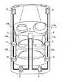
次に、実施形態を挙げ、本発明をより詳しく説明する。本実施形態は、本発明のバス通信システムを車両の乗員を保護するエアバッグ装置に適用した場合を例に挙げて説明する。まず、本実施形態のエアバッグ装置の全体構成について、図1を参照して説明する。図1は、本実施形態のエアバッグ装置1の全体構成の模式図を示す。 Next, the present invention will be described in more detail with reference to embodiments. In the present embodiment, a case where the bus communication system of the present invention is applied to an airbag device that protects a vehicle occupant will be described as an example. First, the whole structure of the airbag apparatus of this embodiment is demonstrated with reference to FIG. FIG. 1 shows a schematic diagram of the overall configuration of an
図1に示すように、エアバッグ装置1(本発明におけるバス通信システム)は、エアバッグECU2(本発明におけるマスタ装置)と、通信バス3、4と、スレーブセンサ5〜12(本発明におけるスレーブ装置)と、運転席用フロントエアバッグ13aと、助手席用フロントエアバッグ13bと、サイドエアバッグ13c、13d、カーテンエアバッグ13e、13fとから構成されている。 As shown in FIG. 1, an airbag device 1 (bus communication system in the present invention) includes an airbag ECU 2 (master device in the present invention),
エアバッグECU2は、後述する内部に設置されたセンサ23と、スレーブセンサ5〜12の検出した加速度に基づいて、エアバッグ13a〜13fを展開させる装置である。このエアバッグECU2は、車両のほぼ中央部に配置されている。 The
通信バス3は、エアバッグECU2からスレーブセンサ5〜8に、電圧を供給すると共に、エアバッグECU2とスレーブセンサ5〜8の間で、識別子信号、指令信号、及び、データなどの送受信をするための信号線である。通信バス4は、エアバッグECU2からスレーブセンサ9〜12に、電圧を供給すると共に、エアバッグECU2とスレーブセンサ9〜12の間で、識別子信号、指令信号、及び、データなどの送受信をするための信号線である。 The
スレーブセンサ5〜12は、車両各部の加速度を検出し、エアバッグECU2からのデータ送信要求指令信号に応じて、通信バス3、4を介して検出結果を送信するセンサである。 The
スレーブセンサ5は、車両の右側後方に配置され、車両の前後方向の加速度を検出する。このスレーブセンサ5は、エアバッグECU2に直接的に接続されている。スレーブセンサ6は、車両の右側Cピラー近傍に配置され、車両の左右方向の加速度を検出する。このスレーブセンサ6は、スレーブセンサ5を介してエアバッグECU2に接続されている。スレーブセンサ7は、車両の右側Bピラー近傍に配置され、車両の左右方向の加速度を検出する。このスレーブセンサ7は、スレーブセンサ5、6を介してエアバッグECU2に接続されている。スレーブセンサ8は、車両の右側前方に配置され、車両の前後方向の加速度を検出する。このスレーブセンサ8は、スレーブセンサ5〜7を介してエアバッグECU2に接続されている。つまり、スレーブセンサ5〜8は、エアバッグECU2にデイジーチェーン接続されている。 The
スレーブセンサ9は、車両の左側後方に配置され、車両の前後方向の加速度を検出する。このスレーブセンサ9は、エアバッグECU2に直接的に接続されている。スレーブセンサ10は、車両の左側Cピラー近傍に配置され、車両の左右方向の加速度を検出する。このスレーブセンサ10は、スレーブセンサ9を介してエアバッグECU2に接続されている。スレーブセンサ11は、車両の左側Bピラー近傍に配置され、車両の左右方向の加速度を検出する。このスレーブセンサ11は、スレーブセンサ9、10を介してエアバッグECU2に接続されている。スレーブセンサ12は、車両の左側前方に配置され、車両の前後方向の加速度を検出する。このスレーブセンサ12は、スレーブセンサ9〜11を介してエアバッグECU2に接続されている。つまり、スレーブセンサ9〜11は、エアバッグECU2にデイジーチェーン接続されている。 The
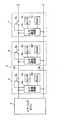
次に、エアバッグ装置1の詳細なブロック構成について図2を参照して説明する。図2は、エアバッグ装置1のブロック図を示す。図2に示すように、エアバッグECU2は、電源回路20と、センター制御回路21と、ECU通信回路22と、センサ23と、点火回路24とから構成されている。 Next, a detailed block configuration of the
電源回路20は、イグニッションスイッチ14を介して供給されるバッテリ15の出力電圧を、センター制御回路21、ECU通信回路22、及びセンサ23の作動に適した電源電圧に変換して供給する回路である。電源回路20の入力端子は、イグニッションスイッチ14を介してバッテリ15の正極端子に接続されている。また、電源回路20の出力端子は、センター制御回路21、ECU通信回路22、及びセンサ23の電源端子にそれぞれ接続されている。なお、バッテリ15の負極端子は車体に接地されている。 The
センター制御回路21は、識別子付与部211と、衝突処理部212と、故障検出部213とから構成される。 The
識別子付与部211は、作動開始直後の初期設定時、すなわち、イグニッションスイッチ14のオン直後に、スレーブセンサ5〜12のそれぞれに対して固有の識別子を付与する。この識別子付与部211の詳細な処理については、後述する。 The
衝突処理部212は、ECU通信回路22及び通信バス3、4を介してスレーブセンサ5〜12の加速度データ、及び、センサ23の加速度データを収集する。そして、衝突処理部212は、これらの加速度データに基づいて、各エアバッグ13a〜13fを展開するか否かを判定する。以下、この判定を衝突判定という。そして、この衝突判定の結果に基づいて、点火回路24を制御する。この衝突処理部212は、故障検出部213による故障禁止処理により、スレーブセンサ5〜12のうち何れの加速度データを用いて衝突判定を行うようにしている。この衝突処理部212の詳細な処理については、後述する。 The
故障検出部213は、スレーブセンサ5〜12のバススイッチがショート故障又はオープン故障であるか否かを検出する。この故障検出部213の詳細な処理については、後述する。 The
ECU通信回路22は、通信バス3、4を介してスレーブセンサ5〜12に電源電圧を供給する。さらに、ECU通信回路22は、スレーブセンサ5〜12との間で、識別子付与信号、識別子取得信号I(本発明における応答電流信号)、データ送信要求指令信号及び加速度データ信号などの各種信号を送受信する回路である。ここで、ECU通信回路22がスレーブセンサ5〜12へ送信する各種信号は、電圧デジタル信号からなる。一方、ECU通信回路22がスレーブセンサ5〜12から受信する各種信号は、電流デジタル信号からなる。このように、電圧デジタル信号を送信側に用いて、電流デジタル信号を受信側に用いることで、信号の送受信を並行して行うことができる。 The
センサ23は、エアバッグECU2内に設置され、車両の前後方向の加速度を検出し、この加速度データをセンター制御回路21の衝突処理部212に出力する。点火回路24は、センター制御回路21の衝突処理部212から出力される点火信号に基づいて、各エアバッグ13a〜13fから選択されたものを展開させる回路である。通信バス3、4は、ECU通信回路22から電圧デジタル信号が送信されるハイサイド通信バス3a、4aと、各スレーブセンサ5〜12からECU通信回路22へ電流デジタル信号が送信されるローサイド通信バス3b、4bとから構成されている。 The
次に、スレーブセンサ5〜12の詳細な構成について、図3を参照して説明する。図3は、特にスレーブセンサ5〜7のブロック図を示す。ここで、スレーブセンサ5〜12は、何れも同じ構成であるため、ここでは、スレーブセンサ5のみについて説明する。 Next, a detailed configuration of the
図3に示すように、スレーブセンサ5は、センサ通信回路5a(本発明における識別子取得手段)と、バススイッチ5b(本発明における切替手段)と、センサ5cと、RAM5dとから構成される。 As shown in FIG. 3, the
センサ通信回路5aの上端側が、ハイサイド通信バス3aに接続されている。一方、センサ通信回路5aの下端側が、ローサイド通信バス3bに接続されている。そして、このセンサ通信回路5aは、ハイサイド通信バス3aを介して、ECU通信回路22から供給される電源電圧をセンサ5cなどに供給する。さらに、センサ通信回路5aは、ECU通信回路22からハイサイド通信バス3aを介して、識別子付与信号を入力した場合には、当該識別子を後述するRAM5dに記憶させると共に、識別子取得信号IをECU通信回路22へ送信する。また、センサ通信回路22は、ECU通信回路22からデータ送信要求指令信号を入力した場合には、センサ5cから加速度データを入力し、当該加速度データをローサイド通信バス3bを介してECU通信回路22へ送信する。さらに、センサ通信回路5aは、ECU通信回路22から入力される信号に基づいて、バススイッチ5bのオン/オフの切り替えを行う。 The upper end side of the sensor communication circuit 5a is connected to the high
バススイッチ5bの一端側(図3の左側)は、ECU通信回路22に直接接続されているハイサイド通信バス3aに接続されている。一方、バススイッチ5bの他端側(図3の右側)は、当該スレーブセンサ5とその後段側に位置するスレーブセンサ6との間を接続するハイサイド通信バス3aに接続されている。つまり、バススイッチ5bは、前段側に位置するECU通信回路22と後段側に位置するスレーブセンサ6とを接続するスイッチである。また、バススイッチ5bの一端側には、上述したセンサ通信回路5aの上端側が接続されている。従って、スレーブセンサ5のバススイッチ5bは、ECU通信回路22と後段のスレーブセンサ6のセンサ通信回路6aとの通信を可能とするスイッチでもある。このバススイッチ5bは、センサ通信回路5aの指示に従って、オン/オフの切り替えを行う。 One end side (the left side in FIG. 3) of the
センサ5cは、加速度を検出し、検出した加速度データをセンサ通信回路5aに出力する。RAM5dは、センサ通信回路5aが識別子付与信号を入力した場合に、センサ通信回路5aにより付与された識別子を記憶する。 The
なお、スレーブセンサ5の後段には、同様の構成であるスレーブセンサ6がハイサイド通信バス3a及びローサイド通信バス3bを介して接続されている。このスレーブセンサ6の後段には、同様の構成であるスレーブセンサ7がハイサイド通信バス3a及びローサイド通信バス3bを介して接続されている。このスレーブセンサ7の後段には、同様の構成であるスレーブセンサ8がハイサイド通信バス3a及びローサイド通信バス3bを介して接続されている。また、スレーブセンサ9〜12についても、スレーブセンサ5〜8と同様であるので、説明を省略する。 A
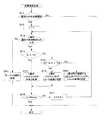
次に、図2〜図7を参照して、エアバッグ装置1の動作について説明する。ここで、図4は、識別子付与部211による識別子付与処理を示すフローチャートである。図5は、識別子取得信号Iを説明する図である。図6は、故障検出部213による故障検出処理を示すフローチャートである。図7は、衝突処理部212による衝突処理を示すフローチャートである。 Next, the operation of the
まず、図2において、イグニッションスイッチ14がオンすると、電源回路20は、バッテリ15の出力電圧を、センター制御回路21、ECU通信回路22、及びセンサ23の作動に適した電源電圧に変換して供給する。このとき、スレーブセンサ5〜12のバススイッチ5b、・・・、12bは全てオフしている。 First, in FIG. 2, when the
続いて、センター制御回路21の識別子付与部211が、スレーブセンサ5〜12に対して識別子付与処理を行う。この識別子付与処理について、図4を参照して説明する。 Subsequently, the
図4に示すように、まず、カウンタnを1に初期化する(ステップS1)。続いて、識別子付与部211は、n番の識別子の付与信号をECU通信回路22のCH1及びハイサイド通信バス3aを介して、スレーブセンサ5〜8側へ出力する(ステップS2)。このとき、スレーブセンサ5〜12のバススイッチ5b、・・・、12bは全てオフしているので、識別子付与部211から出力される1番の識別子付与信号は、スレーブセンサ5のみに伝送される。そうすると、スレーブセンサ5のセンサ通信回路5aは、1番の識別子を取得するので、RAM5dに1番の識別子を記憶させる。さらに、センサ通信回路5aは、1番の識別子を取得した識別子取得信号I1をローサイド通信バス3bを介してECU通信回路22へ出力する。 As shown in FIG. 4, first, the counter n is initialized to 1 (step S1). Subsequently, the
ここで、識別子取得信号Iについて、図5を参照して説明する。図5の最上段に示すように、スレーブセンサ5のセンサ通信回路5aは、例えば8ビットの電流デジタル信号からなる識別子取得信号I1をECU通信回路22へ出力する。ここで、識別子取得信号Iの上位3ビットは識別子ビットとし、下位5ビットはデータビットとしている。そして、第1の識別子取得信号I1は、図5の第1段目に示すように、識別子ビットが「001」となり、データビットが「00001」となる。 Here, the identifier acquisition signal I will be described with reference to FIG. As shown in the uppermost part of FIG. 5, the sensor communication circuit 5 a of the
続いて、識別子付与部211は、n番の識別子取得信号Inを入力したか否かを判定する(ステップS3)。ここでは、スレーブセンサ5から1番の識別子取得信号I1を入力する。そして、識別子付与部211がn番の識別子取得信号Inを入力した場合には(ステップS3:Yes)、カウンタnが同じ通信バス3a、3bにデイジーチェーン接続されているスレーブセンサ5〜8の数Nmaxに等しいか否かを判断する(ステップS4)。ここでは、カウンタnは、1であるので、Nmaxに等しくない。 Subsequently, the
従って、次は、識別子付与信号211は、スレーブセンサ5〜8に対して、n番のバススイッチ5b、・・・、8bのスイッチオン信号を出力する(ステップS5)。まずは、カウンタnが1であるので、1番の識別子を有するスレーブセンサ5のバススイッチ5bがオンする。続いて、カウンタnを1加算して(ステップS6)、ステップS2へ移動する。 Therefore, next, the
つまり、カウンタnが2となると、ステップS2において、識別子付与部211は、2番の識別子の付与信号を出力する。このとき、スレーブセンサ5〜8のうちバススイッチ5bのみがオンされているので、ECU通信回路22のCH1には、スレーブセンサ5、6が接続されていることになる。そして、スレーブセンサ5のRAM5dには1番の識別子が記憶されているので、2番の識別子付与信号は、スレーブセンサ6へ伝送される。そうすると、スレーブセンサ6のセンサ通信回路6aは、2番の識別子を取得するので、RAM6dに2番の識別子を記憶させる。さらに、センサ通信回路6aは、2番の識別子を取得した識別子取得信号I2をローサイド通信バス3bを介してECU通信回路22へ出力する。ここで、2番の識別子取得信号I2の識別子ビットは、「010」となり、データビットは「00001」となる。 That is, when the counter n becomes 2, in step S2, the
このようにして、全てのスレーブセンサ5〜12に対して固有の識別子を設定した場合には、ステップS4において、カウンタnがNmaxとなり、処理を終了する。ところで、ステップS3において、識別子付与部211がn番の識別子取得信号Inを入力しない場合にも(ステップS3:No)、処理は終了する。識別子付与部211がn番の識別子取得信号Inを入力しない場合とは、例えば、バススイッチ5bなどがオープン故障した場合やショート故障した場合などである。 When unique identifiers are set for all the
ここで、例えば、バススイッチ5bがオープン故障した場合の識別子付与処理の流れについて説明する。 Here, for example, the flow of identifier assignment processing when the
この場合、スレーブセンサ5は、上述と同様に、1番の識別子を取得し、識別子取得信号I1を識別子付与部211へ出力する。続いて、ステップS5において、1番のバススイッチ5bのオン信号が出力されたとしても、当該バススイッチ5bはオープン故障であるため、オンされない。そのまま次のステップS2へ進み、識別子付与部211が2番の識別子付与信号を出力する。しかし、バススイッチ5bがオンされないため、ECU通信回路22とスレーブセンサ6とは、通信ができない状態となる。従って、識別子付与部211は、2番の識別子付与信号に対する識別子取得信号I2を入力しない。つまり、ステップS3において、2番の識別子付与信号を出力したにも関わらず、2番の識別子取得信号I2を入力しないので(ステップS3:No)、識別子付与処理は終了する。 In this case, the
また、スレーブセンサ5のバススイッチ5bがショート故障した場合の識別子付与処理の流れについて説明する。 In addition, the flow of the identifier assigning process when the
この場合、スレーブセンサ5は、上述と同様に、1番の識別子を取得し、識別子取得信号I1を識別子付与部211へ出力する。ここで、バススイッチ5bがショート故障しているので、ECU通信回路22には、スレーブセンサ5及びスレーブセンサ6が通信可能な状態となっている。従って、識別子付与部211が出力した1番目の識別子付与信号は、スレーブセンサ5のみならず、スレーブセンサ6へ入力される。従って、スレーブセンサ6は、1番目の識別子を取得し、1番の識別子をRAM6dに記憶し、1番の識別子取得信号I1を識別子付与部211へ出力する。つまり、1番の識別子は、スレーブセンサ5とスレーブセンサ6に設定されることになる。 In this case, the
続いて、2番以降の識別子は、スレーブセンサ7以降に設定される。そうすると、識別子付与部211は、最後に4番の識別子付与信号を出力したとしても、その識別子取得信号I4を入力しない。従って、ステップS3において、4番の識別子付与信号を出力したにもかかわらず、4番の識別子取得信号I4を入力しないので(ステップS3:No)、識別子付与処理は終了する。 Subsequently, the second and subsequent identifiers are set after the
ここで、識別子付与処理と同時に、故障検出部213による故障検出処理が行われる。この故障検出処理について、図5及び図6を参照して説明する。 Here, a failure detection process by the
まず、図5を参照して、スレーブセンサ5のバススイッチ5bがショート故障している場合において、故障検出部213が入力する識別子取得信号Iの最大電流値について説明する。図5の第1段目のビットデータは、スレーブセンサ5のセンサ通信回路5aが出力した識別子取得信号Iである。そして、スレーブセンサ5のバススイッチ5bがショート故障している場合には、スレーブセンサ6のセンサ通信回路6aが出力する識別子取得信号Iは、図5の第2段目のビットデータとなる。つまり、スレーブセンサ5のバススイッチ5bがショート故障している場合には、センサ通信回路5aとセンサ通信回路6aの出力する識別子取得信号Iは同一データとなる。 First, the maximum current value of the identifier acquisition signal I input by the
このとき、故障検出部213が入力する識別子取得信号Iは、センサ通信回路5aとセンサ通信回路6aが出力する識別子取得信号Iを合成したデータとなる。これは、識別子取得信号Iが電流信号であるためである。故障検出部213が入力する識別子取得信号Iは、図5の最下段に示すように、上位から3ビット目と最下位ビットが、センサ通信回路5aのみが出力する識別子取得信号Iの2倍の電流値を示すことになる。
このことを踏まえて、故障検出部213による故障検出処理について説明する。図6に示すように、まず、識別子付与処理が開始されたか否かを判定する(ステップS11)。識別子付与処理が開始されていないのであれば、そのまま処理を終了する。識別子付与処理が開始された場合には(ステップS11:Yes)、カウンタnを1に初期化する(ステップS12)。続いて、故障検出部213は、n番の識別子取得信号Inをスレーブセンサ5〜12から入力したか否かを判定する(ステップS13)。At this time, the identifier acquisition signal I input by the
Based on this, the failure detection processing by the
続いて、入力された識別子取得信号Iが、第1閾値Th1より小さいか否かを判定する(ステップS14)。ここで、識別子取得信号Iは、上述したように、電流デジタル信号からなる。そして、第1閾値Th1は、図5に示すように、1つのセンサ通信回路5aが出力する識別子取得信号Iの最大電流値よりも大きな値としている。ただし、1つのセンサ通信回路5aが出力する識別子取得信号Iの最大電流値の2倍よりも小さな値としている。ここで、識別子取得信号Iのうち特に識別子ビットの電流値と第1閾値Th1とを比較するようにするとよい。これは、同一の識別子が付与されたスレーブセンサ5〜12が出力する識別子取得信号Iのうち識別子ビットは、確実に同一のデータとなるためである。 Subsequently, it is determined whether or not the input identifier acquisition signal I is smaller than the first threshold Th1 (step S14). Here, the identifier acquisition signal I is a current digital signal as described above. As shown in FIG. 5, the first threshold value Th1 is set to a value larger than the maximum current value of the identifier acquisition signal I output from one sensor communication circuit 5a. However, the value is smaller than twice the maximum current value of the identifier acquisition signal I output from one sensor communication circuit 5a. Here, the current value of the identifier bit in the identifier acquisition signal I and the first threshold value Th1 may be compared. This is because the identifier bits in the identifier acquisition signal I output from the
そして、故障検出部213に入力された識別子取得信号Iが、第1閾値Th1より小さい場合には、n番のバススイッチは、正常と判定する(ステップS15)。ここでは、カウンタnが1であるので、1番のバススイッチ5bは正常と判定されることになる。続いて、カウンタnが同じ通信バス3a、3bにデイジーチェーン接続されているスレーブセンサ5〜8の数Nmaxに等しいか否かを判断する(ステップS16)。ここでは、カウンタnは、1であるので、Nmaxに等しくない。 If the identifier acquisition signal I input to the
従って、次は、カウンタnを1加算して(ステップS17)、ステップS13へ移動する。そして、故障検出部213は、順次、全ての識別子取得信号Iを入力し、且つ、全ての識別子取得信号Iが第1閾値Th1よりも小さい場合には、全てのバススイッチが正常であると判定し、処理を終了する。 Therefore, next, the counter n is incremented by 1 (step S17), and the process proceeds to step S13. Then, the
一方、ステップS14において、故障検出部213が入力した識別子取得信号Iが第1閾値Th1以上の場合には(ステップS14:No)、さらに、当該識別子取得信号Iが第2閾値Th2より小さいか否かを判定する(ステップS18)。ここで、第2閾値Th2は、図5に示すように、1つのセンサ通信回路5aが出力する識別子取得信号Iの最大電流値の2倍よりも大きな値であって、3倍よりも小さな値としている。そして、故障検出部213が入力した識別子取得信号Iが第1閾値Th1以上第2閾値Th2未満の場合には(ステップS18:Yes)、n番のバススイッチがショート故障であると判定する(ステップS19)。そして、ステップS16に進み、全てのバススイッチについて故障検出処理を行う。 On the other hand, if the identifier acquisition signal I input by the
また、故障検出部213が入力した識別子取得信号Iが第2閾値以上の場合には(ステップS18:No)、n番以降の連続するバススイッチがショート故障であると判定する(ステップS20)。そして、ステップS16に進み、全てのバススイッチについて故障検出処理を行う。 If the identifier acquisition signal I input by the
また、故障検出部213が、ステップS13において、n番の識別子取得信号Inを入力しない場合には、(n−1)番のバススイッチがオープン故障であると判定し(ステップS21)、処理を終了する。なお、n番の識別子取得信号Inを入力しないか否かについては、例えば、識別子付与信号を出力してから所定時間内に故障検出部213が入力する識別子取得信号Iが零であることにより判定することができる。 If the
このように、故障検出部213は、バススイッチがショート故障又はオープン故障であるかを検出することができることに加えて、ショート故障位置及びオープン故障位置を特定することができる。 As described above, the
次に、衝突処理部212による衝突処理について図7を参照して説明する。衝突処理は、まずイグニッションスイッチ14がオンされた直後か否かを判断する(ステップS31)。そして、イグニッションスイッチ14がオンされた直後である場合には(ステップS31:Yes)、故障検出部213により故障と判定されたか否かを判定する(ステップS32)。故障と判定された場合には(ステップS32:Yes)、さらに、ショート故障であるかオープン故障であるかを判定する(ステップS33)。そして、ショート故障の場合には、ショート故障禁止処理を行う(ステップS34)。一方、オープン故障の場合には、オープン故障禁止処理を行う(ステップS35)。 Next, collision processing by the
ここで、ショート故障禁止処理は、ショート故障位置であるバススイッチを備えるスレーブセンサ、及び、当該スレーブセンサの後段のスレーブセンサの使用を禁止する処理である。より詳細には、n番のバススイッチのみがショート故障の場合には、n番のスレーブセンサ及び(n+1)番のスレーブセンサを使用禁止とする。また、n番及び(n+1)番のバススイッチが連続してショート故障の場合には、n番から(n+2)番のスレーブセンサを使用禁止とする。つまり、使用禁止とされるスレーブセンサ以外のスレーブセンサは、使用可能な状態とする。そして、衝突処理部212において、ショート故障により使用禁止とされるスレーブセンサについて記憶する。 Here, the short failure prohibiting process is a process for prohibiting the use of a slave sensor including a bus switch at a short fault position and a slave sensor in the subsequent stage of the slave sensor. More specifically, when only the nth bus switch has a short circuit failure, the nth slave sensor and the (n + 1) th slave sensor are prohibited from being used. In addition, when the nth and (n + 1) th bus switches are continuously short-circuited, use of the nth to (n + 2) th slave sensors is prohibited. In other words, slave sensors other than the slave sensors whose use is prohibited are set in a usable state. Then, the
また、オープン故障禁止処理は、オープン故障位置であるバススイッチを備えるスレーブセンサの後段側に位置するスレーブセンサを使用禁止とする処理である。例えば、1番のバススイッチがオープン故障位置である場合には、2番以降のスレーブセンサを使用禁止とする。つまり、1番のスレーブセンサは使用可能な状態とする。そして、衝突処理部212において、オープン故障により使用禁止とされるスレーブセンサについて記憶する。 The open failure prohibition process is a process for prohibiting the use of a slave sensor located on the rear stage side of a slave sensor having a bus switch at an open failure position. For example, when the first bus switch is in the open failure position, the second and subsequent slave sensors are prohibited. That is, the first slave sensor is in a usable state. Then, the
そして、ショート故障禁止処理が終了した場合(ステップS34)、オープン故障禁止処理が終了した場合(ステップS35)、ステップS32において正常と判定された場合(ステップS32:No)、イグニッションスイッチ14がオンされた直後ではない場合(ステップS31:No)には、スレーブセンサ5〜12に対して、加速度データ送信要求指令信号を出力する(ステップS36)。 When the short failure prohibition process is completed (step S34), the open failure prohibition process is completed (step S35), or when it is determined normal in step S32 (step S32: No), the
そして、スレーブセンサ5のセンサ通信回路5aは、ハイサイド通信バス3aを介して加速度データ送信要求指令信号を入力する。そうすると、センサ通信回路5aは、ローサイド通信バス3bを介して、センサ5cにより検出された加速度データに識別子情報を加えた加速度データ信号を衝突処理部212へ出力する。他のスレーブセンサ6〜12についても同様に行われる。ただし、使用禁止として記憶されたスレーブセンサに対しては、加速度データ送信要求指令信号を出力することはない。つまり、衝突処理部212は、使用可能とされているスレーブセンサに対してのみ、加速度データ送信要求指令信号を出力する。 The sensor communication circuit 5a of the
そうすると、衝突処理部212は、使用可能とされているそれぞれのスレーブセンサ5〜12からそれぞれの識別子情報を含む加速度データ信号を入力する(ステップS37)。続いて、入力された加速度データ信号に基づいて、衝突したか否かを判定する(ステップS38)。そして、衝突していないと判定された場合には(ステップS38:No)、そのまま処理を終了する。一方、衝突したと判定された場合には(ステップS38:Yes)、点火信号を点火回路24へ出力する(ステップS39)。 Then, the
1:エアバッグ装置、 2:エアバッグECU、 3、4:通信バス、
5〜12:スレーブセンサ1: airbag device, 2: airbag ECU, 3, 4: communication bus,
5-12: Slave sensor
Claims (7)
Translated fromJapanese通信バスを介して前記マスタ装置にデイジーチェーン接続される複数のスレーブ装置と、
を備え、
それぞれの前記スレーブ装置は、
前記マスタ装置から出力される切替信号を入力した場合に、前記マスタ装置又は前段の前記スレーブ装置と後段の前記スレーブ装置との間における通信の接続遮断の切り替えを行う切替手段と、
前段側の前記スレーブ装置の前記切替手段が接続された場合であって、前記マスタ装置から出力される識別子付与信号を入力した場合に、それぞれの識別子を取得する識別子取得手段と、
を備えるバス通信システムであって、
前記識別子取得手段は、前記識別子付与信号を入力した場合に、当該識別子付与信号に応じた応答電流信号を前記マスタ装置へ出力し、
前記マスタ装置は、前記識別子取得手段から出力される前記応答電流信号が第1の閾値を超えている場合に前記スレーブ装置の前記切替手段のショート故障位置を特定する故障検出手段と、前記ショート故障位置である前記切替手段を備える前記スレーブ装置に対する使用禁止処理を行う使用禁止処理手段とを備えることを特徴とするバス通信システム。A master device;
A plurality of slave devices daisy chained to the master device via a communication bus;
With
Each said slave device is
When a switching signal output from the master device is input, switching means for switching communication disconnection between the master device or the previous slave device and the subsequent slave device;
When the switching unit of the slave device on the previous stage side is connected, and when an identifier giving signal output from the master device is input, an identifier acquisition unit that acquires each identifier;
A bus communication system comprising:
The identifier acquisition means, when the identifier giving signal is input, outputs a response current signal corresponding to the identifier giving signal to the master device,
The master device includesa failure detection unitthat identifies a short-circuit failure position of the switching unit of the slave devicewhen the response current signal output from the identifier acquisition unitexceeds a first threshold,and the short-circuit failure A bus communication systemcomprising: use prohibition processing means for performing use prohibition processing on the slave device including the switching means that is a position .
前記故障検出手段は、ショート故障の前記切替手段の連続数を検出する請求項1記載のバス通信システム。The first threshold includes a plurality of values,
2. The bus communication system according toclaim 1 , wherein the failure detection means detects a continuous number of the switching means having a short circuit failure.
前記故障検出手段は、前記識別子ビットの電流値を用いて前記ショート故障を検出する請求項1〜3の何れか一項に記載のバス通信システム。The response current signal is composed of digital data including an identifier bit,
The bus communication system according to any one ofclaims 1 to 3 , wherein the failure detection unit detects the short-circuit failure using a current value of the identifier bit.
通信バスを介して前記マスタ装置にデイジーチェーン接続される複数のスレーブ装置と、
を備え、
それぞれの前記スレーブ装置は、
前記マスタ装置から出力される切替信号を入力した場合に、前記マスタ装置又は前段の前記スレーブ装置と後段の前記スレーブ装置との間における通信の接続遮断の切り替えを行う切替手段と、
前段側の前記スレーブ装置の前記切替手段が接続された場合であって、前記マスタ装置から出力される識別子付与信号を入力した場合に、それぞれの識別子を取得する識別子取得手段と、
を備えるバス通信システムであって、
前記識別子取得手段は、前記識別子付与信号を入力した場合に、当該識別子付与信号に応じた応答電流信号を前記マスタ装置へ出力し、
前記マスタ装置は、前記識別子取得手段から出力される前記応答電流信号に基づき前記スレーブ装置の前記切替手段のオープン故障位置を特定する故障検出手段と、前記オープン故障位置である前記切替手段を備える前記スレーブ装置の後段側の前記スレーブ装置に対する使用禁止処理を行う使用禁止処理手段とを備えることを特徴とするバス通信システム。A master device;
A plurality of slave devices daisy chained to the master device via a communication bus;
With
Each said slave device is
When a switching signal output from the master device is input, switching means for switching communication disconnection between the master device or the previous slave device and the subsequent slave device;
When the switching unit of the slave device on the previous stage side is connected, and when an identifier giving signal output from the master device is input, an identifier acquisition unit that acquires each identifier;
A bus communication system comprising:
The identifier acquisition means, when the identifier giving signal is input, outputs a response current signal corresponding to the identifier giving signal to the master device,
The master device includes failure detection meansfor specifying an open failure position of the switching means of the slave device based on the response current signal output from the identifier acquisition means,and the switching means that is the open failure position. A bus communication systemcomprising: use prohibition processing means for performing use prohibition processing for the slave device on the rear stage side of the slave device .
Priority Applications (3)
| Application Number | Priority Date | Filing Date | Title |
|---|---|---|---|
| JP2006052358AJP4656421B2 (en) | 2006-02-28 | 2006-02-28 | Bus communication system |
| DE102007009042ADE102007009042B4 (en) | 2006-02-28 | 2007-02-23 | bus communication |
| US11/711,180US7523239B2 (en) | 2006-02-28 | 2007-02-26 | Bus communication system |
Applications Claiming Priority (1)
| Application Number | Priority Date | Filing Date | Title |
|---|---|---|---|
| JP2006052358AJP4656421B2 (en) | 2006-02-28 | 2006-02-28 | Bus communication system |
Publications (2)
| Publication Number | Publication Date |
|---|---|
| JP2007235347A JP2007235347A (en) | 2007-09-13 |
| JP4656421B2true JP4656421B2 (en) | 2011-03-23 |
Family
ID=38320087
Family Applications (1)
| Application Number | Title | Priority Date | Filing Date |
|---|---|---|---|
| JP2006052358AExpired - Fee RelatedJP4656421B2 (en) | 2006-02-28 | 2006-02-28 | Bus communication system |
Country Status (3)
| Country | Link |
|---|---|
| US (1) | US7523239B2 (en) |
| JP (1) | JP4656421B2 (en) |
| DE (1) | DE102007009042B4 (en) |
Families Citing this family (31)
| Publication number | Priority date | Publication date | Assignee | Title |
|---|---|---|---|---|
| JP5055046B2 (en)* | 2007-07-06 | 2012-10-24 | 株式会社日立超エル・エス・アイ・システムズ | Vending machine and serial bus system suitable for this |
| KR100968865B1 (en)* | 2007-12-17 | 2010-07-09 | 주식회사 애트랩 | Serial communication system and its ID method |
| DE102008050102B4 (en)* | 2008-10-06 | 2010-11-04 | Phoenix Contact Gmbh & Co. Kg | Communication entity for communication via a bus-oriented communication network |
| EP2359237A4 (en)* | 2008-11-28 | 2012-04-25 | Siemens Ag | AUTOMATIC CONTROL SYSTEM AND METHOD FOR EXECUTING A PARALLEL CONTROL PROGRAM |
| JP2010215163A (en)* | 2009-03-18 | 2010-09-30 | Sanden Corp | On-vehicle equipment control system, and identifier setting method in the same system |
| AT509035B1 (en)* | 2009-11-11 | 2013-07-15 | Illumination Network Systems Gmbh | LIGHTING DEVICE AND LIGHTING SYSTEM |
| US8195857B2 (en)* | 2009-12-18 | 2012-06-05 | Infineon Technologies Ag | Coupling devices, system comprising a coupling device and method for use in a system comprising a coupling device |
| JP4957813B2 (en)* | 2010-01-26 | 2012-06-20 | 株式会社デンソー | Communication slave and communication network system |
| CN102236630A (en)* | 2010-04-29 | 2011-11-09 | 鸿富锦精密工业(深圳)有限公司 | Multi-equipment connecting system |
| JP5120486B2 (en) | 2010-11-25 | 2013-01-16 | 株式会社デンソー | Communication device for occupant protection system |
| US9231906B2 (en)* | 2011-10-07 | 2016-01-05 | Defond Components Limited | Method of assigning identification codes to devices in a network |
| US9946675B2 (en)* | 2013-03-13 | 2018-04-17 | Atieva, Inc. | Fault-tolerant loop for a communication bus |
| JP6166586B2 (en)* | 2013-05-17 | 2017-07-19 | 日本特殊陶業株式会社 | In-vehicle sensor and in-vehicle sensor system |
| JP6397725B2 (en)* | 2013-11-21 | 2018-09-26 | 日本特殊陶業株式会社 | In-vehicle sensor, in-vehicle sensor system, and in-vehicle sensor identifier setting method in in-vehicle sensor system |
| JP6115478B2 (en)* | 2014-01-08 | 2017-04-19 | 株式会社デンソー | Communications system |
| JP6391373B2 (en)* | 2014-09-03 | 2018-09-19 | 古河電気工業株式会社 | Master / slave network device |
| EP3015933B1 (en)* | 2014-10-27 | 2019-10-02 | Robert Bosch Gmbh | Transport system |
| DE102015222248A1 (en)* | 2015-11-11 | 2017-05-11 | Robert Bosch Gmbh | Method and control unit for commissioning a sensor series circuit designed in a daisy-chain topology, sensor series circuit in daisy-chain topology and restraint means |
| DE102015121745A1 (en)* | 2015-12-14 | 2017-06-14 | Osram Gmbh | Method for remote management of terminals on a bus, terminal, terminal system and computer program product |
| CN106891848B (en)* | 2015-12-17 | 2019-03-12 | 上海汽车集团股份有限公司 | Expansible airbag control device and method |
| JPWO2017169756A1 (en)* | 2016-03-29 | 2019-02-07 | ソニー株式会社 | Electronic device, driving method, and slave element |
| EP3229388B1 (en)* | 2016-04-06 | 2019-03-27 | Aros Electronics AB | Optical bus |
| EP3301858A1 (en)* | 2016-09-30 | 2018-04-04 | Siemens Aktiengesellschaft | Method and drive device |
| JP7046700B2 (en)* | 2018-04-25 | 2022-04-04 | 矢崎総業株式会社 | Communications system |
| JP6905499B2 (en)* | 2018-10-18 | 2021-07-21 | 矢崎総業株式会社 | Communications system |
| FR3094810B1 (en)* | 2019-04-03 | 2023-01-13 | Thales Sa | System on chip comprising a plurality of master resources |
| US10795845B1 (en)* | 2019-08-23 | 2020-10-06 | Texas Instruments Incorporated | Method and system for auto-addressing nodes on a communication bus |
| JP2023023071A (en)* | 2021-08-04 | 2023-02-16 | 日本電産サンキョー株式会社 | Communication systems and robots |
| CN116155861B (en)* | 2023-04-20 | 2023-07-11 | 杭州视芯科技股份有限公司 | Wired communication system and configuration method of device ID thereof |
| US20240422025A1 (en)* | 2023-06-14 | 2024-12-19 | Lindsay Corporation | System and method for automatically assigning an identification number to a plurality of node controllers in an irrigation system |
| CN120353741B (en)* | 2025-06-24 | 2025-09-05 | 苏州元脑智能科技有限公司 | Integrated circuit bus system, data processing method and programmable logic unit |
Family Cites Families (17)
| Publication number | Priority date | Publication date | Assignee | Title |
|---|---|---|---|---|
| JPS56109055A (en)* | 1980-02-01 | 1981-08-29 | Hitachi Ltd | Data transmitter |
| JPS59112741A (en)* | 1982-11-15 | 1984-06-29 | Matsushita Electric Works Ltd | Remote monitoring device |
| US5333675C1 (en)* | 1986-02-25 | 2001-05-01 | Perkin Elmer Corp | Apparatus and method for performing automated amplification of nucleic acid sequences and assays using heating and cooling steps |
| JP2510221B2 (en)* | 1987-11-19 | 1996-06-26 | 富士通株式会社 | Network node address setting method |
| US5076375A (en)* | 1987-11-30 | 1991-12-31 | Mettler-Toledo, Inc. | Load cell |
| US5245331A (en)* | 1991-02-22 | 1993-09-14 | Allen-Bradley Company, Inc. | Multiple adapter response detection circuit |
| JP3480518B2 (en)* | 1994-09-01 | 2003-12-22 | ダイハツ工業株式会社 | Anti-skid device failure detection method |
| DE19647668A1 (en)* | 1996-11-19 | 1998-05-28 | Bosch Gmbh Robert | Slave station, master station, BUS system and method for operating a BUS system |
| JP3371202B2 (en)* | 1997-01-21 | 2003-01-27 | ニッタン株式会社 | Transmission system |
| DE19813922A1 (en)* | 1998-03-28 | 1999-09-30 | Telefunken Microelectron | Method for operating a restraint system networked via a bus line in the event of a short circuit |
| US6744376B1 (en)* | 1998-08-26 | 2004-06-01 | The Johns Hopkins University | Remote input/output (RIO) smart sensor analog-digital chip |
| US6745270B1 (en)* | 2001-01-31 | 2004-06-01 | International Business Machines Corporation | Dynamically allocating I2C addresses using self bus switching device |
| JP2004084655A (en)* | 2002-06-28 | 2004-03-18 | Denso Corp | Engine starting control device |
| JP2004284382A (en) | 2003-03-19 | 2004-10-14 | Denso Corp | Occupant protective device |
| US7085863B2 (en)* | 2003-10-30 | 2006-08-01 | International Business Machines Corporation | I2C device including bus switches and programmable address |
| US7304566B2 (en)* | 2003-11-19 | 2007-12-04 | Honda Motor Co., Ltd. | Collision detection sensor for vehicle and collision detection device for vehicle |
| JP2006304069A (en) | 2005-04-22 | 2006-11-02 | Denso Corp | Communication equipment |
- 2006
- 2006-02-28JPJP2006052358Apatent/JP4656421B2/ennot_activeExpired - Fee Related
- 2007
- 2007-02-23DEDE102007009042Apatent/DE102007009042B4/ennot_activeExpired - Fee Related
- 2007-02-26USUS11/711,180patent/US7523239B2/ennot_activeExpired - Fee Related
Also Published As
| Publication number | Publication date |
|---|---|
| US20070204082A1 (en) | 2007-08-30 |
| DE102007009042A1 (en) | 2007-08-30 |
| US7523239B2 (en) | 2009-04-21 |
| DE102007009042B4 (en) | 2011-09-22 |
| JP2007235347A (en) | 2007-09-13 |
Similar Documents
| Publication | Publication Date | Title |
|---|---|---|
| JP4656421B2 (en) | Bus communication system | |
| JP4650690B2 (en) | Bus communication system | |
| US5835873A (en) | Vehicle safety system with safety device controllers | |
| JP4591383B2 (en) | Bus communication system | |
| US6449545B1 (en) | Method for data transfer in a restraint system connected to a bus line | |
| JP5626248B2 (en) | Collision determination device | |
| JP3608044B2 (en) | Start-up control device for airbag device | |
| JP2007215102A (en) | Communication device | |
| KR101006094B1 (en) | Airbag control unit | |
| JP3438217B2 (en) | Method and apparatus for controlling data transmission between two modules provided in a motor vehicle | |
| US11167710B2 (en) | Airbag driving apparatus for vehicle and control method thereof | |
| US6295494B1 (en) | Data transfer method in a restraint system connected to a bus line | |
| US20080046148A1 (en) | Control Apparatus for Occupant Restraint Device | |
| JP3714111B2 (en) | Vehicle occupant protection system | |
| KR20010034709A (en) | Device For Controlling Restraint Devices In An Automobile Using Similarly Constructed Data Processing Units | |
| JP3719371B2 (en) | Vehicle occupant protection system | |
| JP2006304069A (en) | Communication equipment | |
| EP2316694A2 (en) | Vehicle collision sensing system, and a method of operating same | |
| JP4306474B2 (en) | Vehicle occupant protection system | |
| JP3798695B2 (en) | Method and apparatus for igniting at least one ignition element against a restraining means of a motor vehicle | |
| JP2012111370A (en) | Communication device for occupant protection system | |
| JP2004268719A (en) | Multiplex-communication system and occupant protection device using it | |
| JPH1117716A (en) | Data communication circuit | |
| JP4380547B2 (en) | Activation control device and activation method for occupant protection device | |
| JPH09269247A (en) | Multiplex communication circuit |
Legal Events
| Date | Code | Title | Description |
|---|---|---|---|
| A621 | Written request for application examination | Free format text:JAPANESE INTERMEDIATE CODE: A621 Effective date:20080401 | |
| A977 | Report on retrieval | Free format text:JAPANESE INTERMEDIATE CODE: A971007 Effective date:20100901 | |
| A131 | Notification of reasons for refusal | Free format text:JAPANESE INTERMEDIATE CODE: A131 Effective date:20100909 | |
| A521 | Request for written amendment filed | Free format text:JAPANESE INTERMEDIATE CODE: A523 Effective date:20101108 | |
| TRDD | Decision of grant or rejection written | ||
| A01 | Written decision to grant a patent or to grant a registration (utility model) | Free format text:JAPANESE INTERMEDIATE CODE: A01 Effective date:20101202 | |
| A01 | Written decision to grant a patent or to grant a registration (utility model) | Free format text:JAPANESE INTERMEDIATE CODE: A01 | |
| A61 | First payment of annual fees (during grant procedure) | Free format text:JAPANESE INTERMEDIATE CODE: A61 Effective date:20101215 | |
| FPAY | Renewal fee payment (event date is renewal date of database) | Free format text:PAYMENT UNTIL: 20140107 Year of fee payment:3 | |
| FPAY | Renewal fee payment (event date is renewal date of database) | Free format text:PAYMENT UNTIL: 20140107 Year of fee payment:3 | |
| R250 | Receipt of annual fees | Free format text:JAPANESE INTERMEDIATE CODE: R250 | |
| R250 | Receipt of annual fees | Free format text:JAPANESE INTERMEDIATE CODE: R250 | |
| LAPS | Cancellation because of no payment of annual fees |