JP4655836B2 - Cell design program and apparatus for optimal placement of base stations on railroad tracks - Google Patents
Cell design program and apparatus for optimal placement of base stations on railroad tracksDownload PDFInfo
- Publication number
- JP4655836B2 JP4655836B2JP2005258004AJP2005258004AJP4655836B2JP 4655836 B2JP4655836 B2JP 4655836B2JP 2005258004 AJP2005258004 AJP 2005258004AJP 2005258004 AJP2005258004 AJP 2005258004AJP 4655836 B2JP4655836 B2JP 4655836B2
- Authority
- JP
- Japan
- Prior art keywords
- section
- base station
- train
- terminal
- cell design
- Prior art date
- Legal status (The legal status is an assumption and is not a legal conclusion. Google has not performed a legal analysis and makes no representation as to the accuracy of the status listed.)
- Expired - Fee Related
Links
Images


Landscapes
- Mobile Radio Communication Systems (AREA)
Description
Translated fromJapanese本発明は、鉄道線路に基地局を最適配置するためのセル設計プログラム及び装置に関する。 The present invention relates to a cell design program and apparatus for optimally arranging base stations on a railroad track.
近年、電車内の多くの乗客が、無線通信機能を有する端末(又は携帯電話機)を用いて、メール又はコンテンツの送受信をするようになってきている。これら端末は、鉄道線路上(又は少し離れて)に配置された無線基地局と通信する。一般に、電車内から接続できる基地局は、鉄道線路を走行する電車内の端末に専用に設置されたものではない。即ち、基地局は、その基地局がカバーするエリア内に存在する全ての端末との間で通信を実現する。 In recent years, many passengers in trains have been using a terminal (or mobile phone) having a wireless communication function to send and receive e-mails or contents. These terminals communicate with a radio base station arranged on the railroad track (or a little away). In general, a base station that can be connected from within a train is not dedicated to a terminal in a train traveling on a railroad track. That is, the base station realizes communication with all terminals existing in the area covered by the base station.
一方で、今後、コンテンツの多様化又は通信料の低廉化によって、無線通信機能を有する端末を用いて送受信される通信トラヒックは、爆発的に増加する可能性がある。これは、電車内の乗客が操作する端末においても同様である。 On the other hand, communication traffic transmitted and received using a terminal having a wireless communication function may increase explosively in the future due to diversification of contents or reduction in communication charges. The same applies to terminals operated by passengers on the train.
電車外に存在する基地局において、電車内の端末との通信は、通信トラヒック源が集団で移動するために、トラヒックの集団移動モデルとして、一般の端末とは別に考える必要がある。電車内の端末の回線品質は、電車の移動速度だけでなく、接続可能な基地局の変化により電車内の端末の回線品質は、時間とともに大きく変動する。特に、CDMA(Code Division Multiple Access)系のシステムでは、端末数の増減も干渉量に大きく影響を与える。 In a base station that exists outside the train, communication with terminals in the train needs to be considered separately from general terminals as a collective movement model of traffic because communication traffic sources move in groups. The line quality of the terminals in the train varies greatly not only with the moving speed of the train but also with the change of connectable base stations. In particular, in a Code Division Multiple Access (CDMA) system, an increase or decrease in the number of terminals greatly affects the amount of interference.
例えば、駅周辺の基地局では、通勤時などの利用者が多い時間帯では、当該基地局に対する同時接続端末数が増えるため、干渉量が大きくなる。また、電車の発着に応じても、同時接続端末数の急激な変動が生じる。一方、駅から離れた場所に設置された基地局においては、電車の往来により、同時接続端末数の変動が生じ、干渉量も大きく変動する。このような状況の下、従来の基地局の配置方法では、電車内の端末が十分な回線品質を確保することが難しく、電車内の端末との通信を主とする基地局は、別途、鉄道線路上に配置する必要もある。 For example, in a base station around a station, in a time zone where there are many users, such as when commuting, the number of simultaneously connected terminals to the base station increases, and the amount of interference increases. In addition, the number of terminals connected at the same time varies rapidly depending on the arrival and departure of the train. On the other hand, in a base station installed at a location distant from the station, the number of simultaneously connected terminals varies due to the arrival and departure of a train, and the amount of interference also varies greatly. Under these circumstances, it is difficult for the terminals in the train to ensure sufficient line quality in the conventional base station arrangement method, and the base station mainly communicating with the terminals in the train It is also necessary to place it on the track.
従って、本発明は、各基地局が収容する端末数に応じて変動する干渉量を考慮すると共に、電車内の端末に対する回線品質が所望値を満たすように、鉄道線路に基地局を最適配置するためのセル設計プログラム及び装置を提供することを目的とする。 Therefore, the present invention considers the amount of interference that varies depending on the number of terminals accommodated by each base station, and optimally arranges the base stations on the railway track so that the line quality for the terminals in the train satisfies a desired value. An object of the present invention is to provide a cell design program and apparatus for the above.
本発明によれば、
鉄道線路における所定の始点から終点までの直線を等間隔の区間i(i=1〜I)に分割し、基地局の最適配置のために、区間jに配置された基地局が、区間iに存在する端末を収容するか否かh(i,j)(=1,0)を決定するように、コンピュータを実行させるセル設計プログラムであって、
目的関数として、基地局数Σj=1If(j)を最小にするために、
制約条件として、区間iに存在する電車内の1端末が基地局jから受信する所望波受信電力に対して、区間iに対する全ての基地局からの干渉量と区間iに存在する電車内の他の全ての端末による干渉量との和との比が、電車内の端末が要求する最低回線品質Q以上となるように、線形計画法を用いて算出するステップを有するようにコンピュータを実行させることを特徴とする。According to the present invention,
A straight line from a predetermined start point to an end point on a railway track is divided into equally spaced sections i (i = 1 to I), and the base station arranged in section j is changed to section i for optimal placement of base stations. A cell design program for causing a computer to execute so as to determine whether or not h (i, j) (= 1,0) to accommodate an existing terminal,
In order to minimize the number of base stations Σj = 1I f (j) as an objective function,
As constraints, for the desired wave received power received from base station j by one terminal in the train existing in section i, the amount of interference from all base stations for section i and other in the train existing in section i The computer is executed so as to have a step of calculating using linear programming so that the ratio of the sum of the interference to the sum of all the terminals is equal to or higher than the minimum channel quality Q required by the terminals in the train. It is characterized by.
本発明における他の実施形態によれば、
制約条件は、
dist(i)≦|i-j+1|+α(1-f(j))、|i-j|≦α
によって算出され、
Qは、電車内の端末が要求する最低回線品質(電力対雑音密度比)であり、
g(i,j)は、区間jに配置された基地局から区間iへの伝搬損失であり、
p(j)は、区間jに配置された基地局から1端末への送信電力であり、
n(k)は、区間kにおける同時接続端末数であり、
Nは、電車内の同時接続端末数であり、
Gは、拡散利得であり、
dist(i)は、区間iに存在する電車内の端末と接続する基地局との距離であり、
αは、基地局と端末とが接続可能な最大距離であり、
分子式は、区間iに存在する電車内の1端末が、区間jに配置された基地局から受信する所望波受信電力であり、
分母左辺式は、区間iに存在する電車内の1端末が受信する、電車外のトラヒックからの干渉電力の総和であり、
分母右辺式は、区間iに存在する電車内の1端末が受信する、電車内の他の端末のトラヒックからの干渉電力の総和である
ようにコンピュータを実行させることも好ましい。According to another embodiment of the invention,
The constraints are
dist (i) ≦ | i-j + 1 | + α (1-f (j)), | ij | ≦ α
Calculated by
Q is the minimum line quality (power-to-noise density ratio) required by the terminal in the train.
g (i, j) is a propagation loss from the base station arranged in section j to section i,
p (j) is the transmission power from the base station arranged in section j to one terminal,
n (k) is the number of simultaneously connected terminals in section k,
N is the number of simultaneously connected terminals in the train,
G is the diffusion gain,
dist (i) is the distance from the base station connected to the terminal in the train existing in section i,
α is the maximum distance that the base station and the terminal can be connected,
The molecular formula is the desired wave received power that one terminal in the train existing in the section i receives from the base station arranged in the section j.
The denominator left-side expression is the sum of the interference power from traffic outside the train that is received by one terminal in the train that exists in section i.
It is also preferable to cause the computer to execute so that the right-hand side expression of the denominator is the sum of interference power from traffic of other terminals in the train received by one terminal in the train existing in the section i.
また、本発明によれば、
鉄道線路における所定の始点から終点までの直線を等間隔の区間i(i=1〜I)に分割し、電車は始点の出発時間t=0から終点の到着時間t=Tまで走行したとして、基地局の最適配置のために、区間iに基地局f(j)(=1,0)を配置するか否かを決定するように、コンピュータを実行させるセル設計プログラムであって、
目的関数として、基地局数Σ1If(j)を最小にするために、
制約条件として、時間tについて電車内の1端末が区間iの基地局から受信した所望波受信電力r(t,i)に対する、時間tにおける区間iの基地局以外の基地局からの干渉量の比が、電車内の端末が要求する最低回線品質Q以上となるように、線形計画法を用いて算出するステップを有するようにコンピュータを実行させることを特徴とする。Moreover, according to the present invention,
Dividing the straight line from the predetermined start point to the end point on the railway track into equally spaced sections i (i = 1 to I), A cell design program that causes a computer to execute whether or not to arrange a base station f (j) (= 1,0) in a section i for optimal arrangement of base stations,
As an objective function, to the base station number sigma1I f the (j) to a minimum,
As a constraint, the amount of interference from a base station other than the base station in section i at time t with respect to the desired wave received power r (t, i) received by one terminal in the train from the base station in section i at time t. The computer is executed so as to have a step of calculating using linear programming so that the ratio is equal to or higher than the minimum line quality Q required by the terminal in the train.
本発明における他の実施形態によれば、
線形計画法を用いて算出するステップについて、時間tにおける区間iの基地局以外の基地局からの干渉量は、
Q'は、電車内の端末が要求する最低回線品質(電力対雑音密度比)であり、
n(t,i)は、時間tについて区間iの基地局との同時接続端末数であり、
m(t)は、時間tについて電車内の端末が接続する基地局が存在する区間であり、
r(t、m(t))は、時間tについて電車内の1端末が、区間m(t)に存在する基地局から受信する電力であり、
分母式は、全ての基地局からの受信電力から、当該端末の前記所望波受信電力r(t,i)を差し引いた量である
ようにコンピュータを実行させることも好ましい。According to another embodiment of the invention,
For the step of calculating using linear programming, the amount of interference from base stations other than the base station in section i at time t is
Q ′ is the minimum line quality (power-to-noise density ratio) required by the terminal in the train,
n (t, i) is the number of simultaneously connected terminals with the base station in section i for time t,
m (t) is a section where a base station to which a terminal in the train is connected at time t exists,
r (t, m (t)) is the power received by one terminal in the train from the base station existing in the section m (t) at time t,
It is also preferable that the denominator is executed by the computer so that the denominator is an amount obtained by subtracting the desired wave received power r (t, i) of the terminal from the received power from all base stations.
更に、本発明における他の実施形態によれば、CDMA方式に基づく基地局を配置するためのものであることも好ましい。 Furthermore, according to another embodiment of the present invention, it is also preferable to arrange a base station based on the CDMA scheme.
更に、本発明によれば、コンピュータを搭載したセル設計シミュレーション装置であって、前述したセル設計プログラムを、コンピュータによって実行させることを特徴とする。 Furthermore, according to the present invention, a cell design simulation apparatus equipped with a computer is characterized in that the above-described cell design program is executed by a computer.
本発明によれば、各基地局が収容する端末数に応じて変動する干渉量を考慮すると共に、電車内の端末に対する回線品質が所望値を満たすように、鉄道線路に最小数の基地局を最適配置することができる。 According to the present invention, a minimum number of base stations are provided on the railway line so that the amount of interference that varies depending on the number of terminals accommodated by each base station is taken into account, and the line quality for the terminals in the train satisfies a desired value. Optimal placement can be achieved.
本発明によれば、鉄道線路における所定の始点から終点までの直線を等間隔の区間に分割し、1次元モデルとして基地局の最適配置を導出することができる。1次元モデルとして扱うことにより、複雑且つ多様な情報量を考慮することなく、線形計画法によって比較的少ない計算量で導出することができる。 According to the present invention, it is possible to divide a straight line from a predetermined start point to an end point on a railway track into equally spaced sections and derive an optimal arrangement of base stations as a one-dimensional model. By treating it as a one-dimensional model, it can be derived with a relatively small amount of calculation by linear programming without considering complicated and diverse information amounts.
以下では、図面を用いて、本発明を実施するための最良の形態について詳細に説明する。 Hereinafter, the best mode for carrying out the present invention will be described in detail with reference to the drawings.
図1は、基地局及びセルの第1の配置構成図である。 FIG. 1 is a first arrangement configuration diagram of base stations and cells.
図1によれば、電車1が、鉄道線路2を走行する。鉄道線路2の周辺には、複数の基地局3が配置されており、電車内の端末がこれら基地局と通信をすることができる。鉄道線路における所定の始点から終点までの直線は、等間隔の区間i(i=1〜I)に分割される。図1によれば、I=18として18区間に分割されている。また、その鉄道線路の沿線付近には、走行する電車内の端末が無線で通信するための複数の基地局が配置されているとする。 According to FIG. 1, a
区間jに基地局が配置されているか否かをf(j)で表す。1つの区間には、最大1つの基地局が配置されるか(f(j)=1)、又は基地局が配置されないか(f(j)=0)のいずれかである。図1によれば、区間3、区間7、区間12及び区間17に基地局が配置されており、以下のようになる。
f(3)=f(7)=f(12)=f(17)=1
f(1)=f(2)=f(4)=f(5)=f(6)=f(8)=f(9)=f(10)=f(11)=
f(13)=f(14)=f(15)=f(16)=f(18)=0Whether or not a base station is arranged in the section j is represented by f (j). Either one base station is arranged at maximum (f (j) = 1) or no base station is arranged (f (j) = 0) in one section. According to FIG. 1, base stations are arranged in
f (3) = f (7) = f (12) = f (17) = 1
f (1) = f (2) = f (4) = f (5) = f (6) = f (8) = f (9) = f (10) = f (11) =
f (13) = f (14) = f (15) = f (16) = f (18) = 0
図2は、本発明における区間jに配置された基地局が収容する区間iを表す説明図である。 FIG. 2 is an explanatory diagram showing a section i accommodated by a base station arranged in a section j in the present invention.
図2によれば、横軸が区間i=1〜I(I=18)を表し、縦軸は基地局が配置された区間j(j=3,7,12,17)を表す。区間jに配置された基地局が、区間iに存在する端末を収容するか(h(i,j)=1)、又は収容しないか(h(i,j)=0)のいずれかである。図2によれば、以下のようになる。図2の表は、線形計画法を解くための行列として表される。
区間j=3に配置された基地局が、区間i=1,2,3,4を収容するとする。
h(1,3)=h(2,3)=h(3,3)=h(4,3)=1
区間j=7に配置された基地局が、区間i=5,6,7,8,9を収容するとする。
h(5,7)=h(6,7)=h(7,7)=h(8,7)=h(9,7)=1
区間j=12に配置された基地局が、区間i=10,11,12,13,14を収容するとする。
h(10,12)=h(11,12)=h(12,12)=h(13,12)=h(14,12)=1
区間j=17に配置された基地局が、区間i=15,16,17,18を収容するとする。
h(15,17)=h(16,17)=h(17,17)=h(18,17)=1
その他のh(i,j)は、0となる。According to FIG. 2, the horizontal axis represents the interval i = 1 to I (I = 18), and the vertical axis represents the interval j (j = 3, 7, 12, 17) in which the base station is arranged. Whether the base station arranged in section j accommodates terminals existing in section i (h (i, j) = 1) or does not accommodate terminals (h (i, j) = 0) . According to FIG. The table of FIG. 2 is represented as a matrix for solving linear programming.
Assume that the base station arranged in section j = 3 accommodates sections i = 1, 2, 3, and 4.
h (1,3) = h (2,3) = h (3,3) = h (4,3) = 1
Assume that the base station arranged in the section j = 7 accommodates the section i = 5, 6, 7, 8, 9.
h (5,7) = h (6,7) = h (7,7) = h (8,7) = h (9,7) = 1
It is assumed that the base station arranged in the section j = 12 accommodates the section i = 10, 11, 12, 13, 14.
h (10,12) = h (11,12) = h (12,12) = h (13,12) = h (14,12) = 1
Assume that the base station arranged in the section j = 17 accommodates the sections i = 15, 16, 17, and 18.
h (15,17) = h (16,17) = h (17,17) = h (18,17) = 1
The other h (i, j) is 0.
図3は、本発明における第1のフローチャートである。 FIG. 3 is a first flowchart in the present invention.
(S301)始点から終点までの直線を、等間隔の区間iに分割する。本発明は、1次元モデルについて基地局の最適配置を導出する。(S301) The straight line from the start point to the end point is divided into equally spaced sections i. The present invention derives an optimal arrangement of base stations for a one-dimensional model.
(S302)全てについてf(j)=0、h(i,j)=0とする。
(S303)既存の基地局を考慮するか否かを判定する。区間jに既に配置された基地局を固定することにより、別途設置すべき基地局の配置のみを決定することができる。
(S304)既存の基地局を考慮する場合、配置された基地局の区間について、f(j)=1、h(i,j)=1とする。(S302) f (j) = 0 and h (i, j) = 0 for all.
(S303) It is determined whether to consider an existing base station. By fixing the base stations already arranged in the section j, it is possible to determine only the arrangement of base stations to be separately installed.
(S304) When considering an existing base station, f (j) = 1 and h (i, j) = 1 are set for the section of the arranged base station.
(S305)線形計画法を解くためのパラメータとして、p(j)、g(i,j)、n(k)を予め決定する。
g(i,j)は、区間jに配置された基地局から区間iへの伝搬損失である。
p(j)は、区間jに配置された基地局から1端末への送信電力である。
n(k)は、区間kにおける同時接続端末数である。(S305) p (j), g (i, j), and n (k) are determined in advance as parameters for solving the linear programming.
g (i, j) is a propagation loss from the base station arranged in section j to section i.
p (j) is the transmission power from the base station arranged in section j to one terminal.
n (k) is the number of simultaneously connected terminals in the interval k.
基地局の設置場所が決まれば、その位置から当該区間までの伝搬損失g(i,j)は、実測又は所定計算式により導出することができる。電車内の端末が基地局から受信する受信電力は、区間jに配置された基地局の送信電力p(j)と、その基地局が配置された区間jから区間iまでの伝搬損失g(i,j)との乗算によって導出される。 If the installation location of the base station is determined, the propagation loss g (i, j) from the position to the section can be derived by actual measurement or a predetermined calculation formula. The received power received by the terminal in the train from the base station is the transmission power p (j) of the base station arranged in the section j and the propagation loss g (i from the section j to the section i in which the base station is arranged. , j).
更に、当該基地局が収容する区間kにおける同時接続端末数も考慮する。同時接続端末数は、干渉量に影響を与えるため、セル設計において重要なパラメータである。例えば、駅周辺の基地局では、通勤時などの利用者が多い時間帯では、当該基地局に対する同時接続端末数が増えるため、干渉量が大きくなる。また、電車の発着に応じても、同時接続端末数の急激な変動が生じる。一方、駅から離れた場所に設置された基地局においては、電車の往来により、同時接続端末数の変動が生じ、干渉量も大きく変動する。従って、区間kにおけるトラヒック量は、将来的に増加するであろう電車内の通信トラヒックを考慮して、シミュレーション的に決定することができる。 Furthermore, the number of simultaneously connected terminals in section k accommodated by the base station is also considered. Since the number of simultaneously connected terminals affects the amount of interference, it is an important parameter in cell design. For example, in a base station around a station, in a time zone where there are many users, such as when commuting, the number of simultaneously connected terminals to the base station increases, and the amount of interference increases. In addition, the number of terminals connected at the same time varies rapidly depending on the arrival and departure of the train. On the other hand, in a base station installed at a location distant from the station, the number of simultaneously connected terminals varies due to the arrival and departure of a train, and the amount of interference also varies greatly. Therefore, the traffic volume in the section k can be determined by simulation in consideration of communication traffic in the train that will increase in the future.
(S306)線形計画法を解いて、基地局数Σj=1If(j)が最小となるように、基地局を配置する区間を決定する。
(S307)最終的に、鉄道線路における基地局の最適配置のためのf(j)及びh(i,j)が導出される。本発明によって導出される新たな基地局の設置場所は、将来増加する電車内の通信トラヒックを収容することを目的としているため、沿線付近を対象とする。(S306) The linear programming method is solved, and the interval in which the base station is arranged is determined so that the number of base stations Σj = 1I f (j) is minimized.
(S307) Finally, f (j) and h (i, j) for optimal arrangement of base stations on the railway track are derived. Since the installation location of the new base station derived by the present invention is intended to accommodate communication traffic in the train that will increase in the future, it is targeted for the vicinity of the railway line.
本発明によれば、ユーザの操作する端末が電車内にあり、電車が何れの区間に存在していても、所定以上の品質の電波を受信することができる。その上で、設置する基地局数を最小とすることを目的とする。尚、端末は、最寄りの基地局を利用することを前提とし、離れた基地局を利用することはないとする。また、1つの端末は1つの基地局とのみ通信し、複数の基地局と同時に通信をすることは考慮しない。 According to the present invention, a terminal operated by a user is in a train, and it is possible to receive radio waves having a quality of a predetermined level or higher regardless of which section the train is in. In addition, the purpose is to minimize the number of base stations to be installed. It is assumed that the terminal uses the nearest base station and does not use a remote base station. Also, one terminal communicates with only one base station and does not consider communicating with a plurality of base stations simultaneously.
以下では、線形計画法について詳細に説明する。 In the following, the linear programming will be described in detail.
目的関数は、以下のように決定される。
Minimize Σ1If(j)The objective function is determined as follows.
Minimize Σ1I f (j)
目的関数は、鉄道線路全域に渡って基地局数Σj=1If(j)を最小にすることを目的とする。例えば、図1によれば、基地局数をΣ118f(j)=4とし、図2のように基地局が収容する区間が決定されている。Objective function aims to minimize the base station numberΣ j = 1 I f (j ) over the railway tracks throughout. For example, according to FIG. 1, the number of base stations is Σ118 f (j) = 4, and the section accommodated by the base station is determined as shown in FIG.
制約条件は、以下のようになる。目的関数のように最小の基地局数であって、且つ、全区間において電車内の端末の回線品質が所望値を満足するように、基地局の設置要否を判定する。
Qは、電車内の端末が要求する最低回線品質(電力対雑音密度比)である。
Nは、電車内の同時接続端末数である。
Gは、拡散利得である。
dist(i)は、区間iに存在する電車内の端末と接続する基地局との距離である。
αは、基地局と端末とが接続可能な最大距離(区間数)である。例えばα=4とする。Q is the minimum line quality (power-to-noise density ratio) required by the terminal in the train.
N is the number of simultaneously connected terminals in the train.
G is a diffusion gain.
dist (i) is the distance from the base station connected to the terminal in the train existing in section i.
α is the maximum distance (number of sections) at which the base station and the terminal can be connected. For example, α = 4.
Σj=1If(j)≧1は、基地局は必ず1つ以上存在することを意味する。
Σj=i-αi+αh(i,j)=1は、1つの区間には、基地局を多くとも1つしか設置しないことを意味する。
h(i,j)≦f(j)、i-α≦j≦i+αは、1つの区間をカバーするのは1つの基地局のみであることを意味する。Σj = 1I f (j) ≧ 1 means that there is always at least one base station.
Σj = i−αi + α h (i, j) = 1 means that at most one base station is installed in one section.
h (i, j) ≦ f (j), i−α ≦ j ≦ i + α means that only one base station covers one section.
以下の分子式は、区間iに存在する電車内の1端末が、区間jに配置された基地局から受信する所望波受信電力である。
例えば、区間i=2に存在する電車内の1端末が受信する、所望基地局からの所望波受信電力を考える。α=4とすると、区間j=(2−4)〜(2+4)=1〜6に配置された基地局が対象となる。また、区間3に配置された基地局が、区間1〜4を収容するとするならば、以下のようになる。
h(2,3)=1
h(2,1)=h(2,2)=h(2,4)=h(2,5)=h(2,6)=0For example, consider the desired wave received power from the desired base station received by one terminal in the train existing in the section i = 2. If α = 4, base stations arranged in the section j = (2-4) to (2 + 4) = 1 to 6 are targeted. Further, if the base station arranged in the
h (2,3) = 1
h (2,1) = h (2,2) = h (2,4) = h (2,5) = h (2,6) = 0
そうすると、分子式は、以下のようになる。
G・{h(2,1)p(1)g(2,1)+h(2,2)p(2)g(2,2)+h(2,3)p(3)g(2,3)+
h(2,4)p(4)g(2,4)+h(2,5)p(5)g(2,5)+h(2,6)p(6)g(2,6)}
=G・{h(2,3)p(3)g(2,3)}
=G・p(3)g(2,3)Then, the molecular formula is as follows.
G · {h (2,1) p (1) g (2,1) + h (2,2) p (2) g (2,2) + h (2,3) p (3) g (2,3 ) +
h (2,4) p (4) g (2,4) + h (2,5) p (5) g (2,5) + h (2,6) p (6) g (2,6)}
= G · {h (2,3) p (3) g (2,3)}
= G ・ p (3) g (2,3)
p(3)は、区間3に配置された基地局から1端末への送信電力を意味する。g(2,3)は、区間3から区間2までの間の伝搬損失を意味する。そうすると、p(3)g(2,3)は、区間2に存在する電車内の1端末が、区間3に配置された基地局から受けた所望波受信電力を意味する。 p (3) means transmission power from the base station arranged in
Gは、拡散利得を意味する。拡散符号化通信方式(CDMA)においては、拡散符号化により過度な干渉を受けない。従って、電車内の1端末の受信電力に、拡散利得Gを乗算することにより、分母式の干渉量に対する耐性を高めて端末の通信品質を算出することができる。 G means diffusion gain. In spread coded communication (CDMA), excessive interference is not caused by spread coding. Therefore, by multiplying the received power of one terminal in the train by the spreading gain G, it is possible to increase the tolerance against the denominator interference amount and calculate the communication quality of the terminal.
以下の分母左辺式は、区間iに存在する電車内の1端末が受信する、電車外のトラヒックからの干渉電力の総和である。
分母左辺式におけるp(j)g(i,j)は、区間iにおける基地局jからの受信電力を表す。α=4とすると、k=(3−4)〜(3+4)=1〜7の区間が対象となる。また、区間3に配置された基地局が、区間1〜4を収容するとするならば、以下のようになる。
h(1,3)=h(2,3)=h(3,3)=h(4,3)=1
h(5,3)=h(6,3)=h(7,3)=0P (j) g (i, j) in the denominator left side expression represents the received power from the base station j in the section i. When α = 4, the section of k = (3-4) to (3 + 4) = 1 to 7 is targeted. Further, if the base station arranged in the
h (1,3) = h (2,3) = h (3,3) = h (4,3) = 1
h (5,3) = h (6,3) = h (7,3) = 0
そうすると、基地局への同時接続端末数は、以下のようになる。
h(1,3)n(1)+h(2,3)n(2)+h(3,3)n(3)+h(4,3)n(4)+h(5,3)n(5)+h(6,3)n(6)+h(7,3)n(3)
=h(1,3)n(1)+h(2,3)n(2)+h(3,3)n(3)+h(4,3)n(4)Then, the number of simultaneously connected terminals to the base station is as follows.
h (1,3) n (1) + h (2,3) n (2) + h (3,3) n (3) + h (4,3) n (4) + h (5,3) n (5) + H (6,3) n (6) + h (7,3) n (3)
= H (1,3) n (1) + h (2,3) n (2) + h (3,3) n (3) + h (4,3) n (4)
区間iにおける基地局jからの受信電力に、同時接続端末数を乗算することにより、区間iに存在する電車内の端末が受ける干渉電力を表す。例えば、区間3に配置された基地局から区間2までの受信電力p(3)g(2,3)を乗算する。
p(3)g(2,3)h(1,3)n(1)+p(3)g(2,3)h(2,3)n(2)+p(3)g(2,3)h(3,3)n(3)+p(3)g(2,3)h(4,3)n(4)By multiplying the received power from the base station j in the section i by the number of simultaneously connected terminals, the interference power received by the terminals in the train existing in the section i is represented. For example, the received power p (3) g (2,3) from the base station arranged in
p (3) g (2,3) h (1,3) n (1) + p (3) g (2,3) h (2,3) n (2) + p (3) g (2,3) h (3,3) n (3) + p (3) g (2,3) h (4,3) n (4)
分母右辺式は、区間iに存在する電車内の1端末が受信する、電車内の他の端末のトラヒックからの干渉電力の総和である。
Nは、電車内のトラヒック量(同時接続端末数)を表す。N−1は、電車内のトラヒック量から当該1端末に対するトラヒックを削除したものである。即ち、電車内の他の端末のトラヒッックによる干渉量を導出する。 N represents the traffic volume in the train (the number of simultaneously connected terminals). N-1 is obtained by deleting the traffic for the one terminal from the traffic volume in the train. That is, the amount of interference due to traffic from other terminals in the train is derived.
区間i=2について検討する。α=4とすると、j=(2−4)〜(2+4)=1〜6となる。
(N−1)・{
h(2,1)p(1)g(2,1)+h(2,2)p(2)g(2,2)+h(2,3)p(3)g(2,3)+h(2,4)p(4)g(2,4)+h(2,5)p(5)g(2,5)+h(2,6)p(6)g(2,6)}
=(N−1)・{h(2,3)p(3)g(2,3)}
=(N−1)・p(3)g(2,3)Consider interval i = 2. When α = 4, j = (2−4) to (2 + 4) = 1 to 6.
(N-1) ・ {
h (2,1) p (1) g (2,1) + h (2,2) p (2) g (2,2) + h (2,3) p (3) g (2,3) + h ( 2,4) p (4) g (2,4) + h (2,5) p (5) g (2,5) + h (2,6) p (6) g (2,6)}
= (N-1). {H (2,3) p (3) g (2,3)}
= (N-1) .p (3) g (2,3)
dist(i)≦|i-j+1|+α(1-f(j))、|i-j|≦αは、最寄りに存在する基地局を無視して、それよりも遠い基地局と通信することはないことを意味する。|i-j+1|は、基地局が存在する区間は1となり、その距離が離れるほど大きい値となる。α(1-f(j))は、基地局が存在するならば0となり、基地局が存在しないならばαとなる。基地局と端末との間の距離は、接続可能な最大距離αよりも短い。 dist (i) ≦ | i-j + 1 | + α (1-f (j)), | ij | ≦ α is to ignore the nearest base station and communicate with a base station farther than that Means no. | I-j + 1 | is 1 in the section where the base station exists, and becomes larger as the distance increases. α (1-f (j)) is 0 if a base station exists, and α if no base station exists. The distance between the base station and the terminal is shorter than the maximum connectable distance α.
前述した第1の実施形態は、電車の走行時間tを考慮することなく、各基地局が収容する端末数に応じて変動する干渉量を考慮すると共に、電車内の端末に対する回線品質が所望値を満たすように、鉄道線路に基地局の最適配置の場所を、区間単位で導出することができる。 The first embodiment described above considers the amount of interference that fluctuates according to the number of terminals accommodated by each base station without considering the train travel time t, and the line quality for the terminals in the train is a desired value. The location of the optimal arrangement of the base stations on the railroad track can be derived in section units so as to satisfy the above.
図4は、基地局及びセルの第2の配置構成図である。 FIG. 4 is a second arrangement configuration diagram of base stations and cells.
図1と比較して、図4は、電車の発車時刻からの経過時間0<t<Tを考慮している。m(t)は、時間tにおける電車内の端末が通信可能な基地局が存在する区間を表す。 Compared with FIG. 1, FIG. 4 considers the elapsed
図4によれば、電車は、現在時間tに区間11を走行中であるとする。その電車内に存在する端末は、時間tにおいて区間12に配置された基地局Cからの受信電力r(t、12)を、所望波受信電力とする。一方、その端末は、基地局A、B及びDからの受信電力は、干渉電力として作用する。 According to FIG. 4, it is assumed that the train is traveling in the
時間tにおいて区間7に配置された基地局Bからの干渉電力は、当該基地局Bからの受信電力r(t、12)と、基地局Bに同時接続される端末数n(t,7)との乗算から算出される。また、時間tにおいて区間17に配置された基地局Dからの干渉電力は、当該基地局Dからの受信電力r(t、17)と、基地局Dに同時接続される端末数n(t,17)との乗算から算出される。更に、時間tにおいて区間3に配置された基地局Aからの干渉電力は、当該基地局Aからの受信電力r(t、3)と、基地局Aに同時接続される端末数n(t,3)との乗算から算出される。 The interference power from the base station B arranged in the
図5は、本発明における第2のフローチャートである。 FIG. 5 is a second flowchart in the present invention.
(S501)始点から終点までの直線を、等間隔の区間iに分割する。本発明は、1次元モデルについて基地局の最適配置を導出する。(S501) The straight line from the start point to the end point is divided into equally spaced sections i. The present invention derives an optimal arrangement of base stations for a one-dimensional model.
(S502)全てについてf(i)=0とする。
(S503)既存の基地局を考慮するか否かを判定する。区間iに既に配置された基地局を固定することにより、別途設置すべき基地局の配置のみを決定することができる。
(S504)既存の基地局を考慮する場合、配置された基地局の区間について、f(i)=1とする。(S502) f (i) = 0 is set for all.
(S503) It is determined whether to consider an existing base station. By fixing the base stations already arranged in the section i, it is possible to determine only the arrangement of base stations to be separately installed.
(S504) When considering an existing base station, f (i) = 1 is set for the section of the arranged base station.
(S505)線形計画法を解くためのパラメータとして、r(t,i)及びn(t,i)を予め決定する。
r(t,i)は、時間tにおいて区間iに配置された基地局から、電車内の1端末が受信する受信電力を表す。
n(t,i)は、時間tにおいて区間iに配置された基地局と接続している端末数を表す。
これらパラメータは、実測値であってもよいし、所定計算式から導出されるシミュレーション値であってもよい。(S505) r (t, i) and n (t, i) are determined in advance as parameters for solving the linear programming.
r (t, i) represents the received power received by one terminal in the train from the base station arranged in section i at time t.
n (t, i) represents the number of terminals connected to the base station arranged in section i at time t.
These parameters may be actual measurement values or simulation values derived from a predetermined calculation formula.
(S506)線形計画法を解いて、基地局数Σj=1If(i)を最小にするように、基地局を配置する区間を決定する。
(S507)最終的に、鉄道線路における基地局の最適配置のためのf(i)が導出される。(S506) by solving the linear programming, a base station number Σj = 1I f (i) is to minimize, to determine the period of placing the base station.
(S507) Finally, f (i) for optimal arrangement of base stations on the railway track is derived.
以下では、線形計画法について詳細に説明する。 In the following, the linear programming will be described in detail.
目的関数は、以下のように決定される。
Minimize Σ1If(i) f(i)={0,1}、1≦j≦IThe objective function is determined as follows.
Minimize Σ1I f (i) f (i) = {0,1}, 1 ≦ j ≦ I
目的関数の左辺式は、鉄道線路全域に渡って基地局数Σj=1If(i)を最小にすることを目的とする。Left-side expression of the objective function aims to minimize the base station numberΣ j = 1 I f (i ) over the railway tracks throughout.
電車は、始点をスタートしてT時間後に終点に到達する。電車内の端末の回線品質は、搬送波電力(Carrier)対干渉電力(Interference)比(C/I値)で表す。その制約条件は、以下のようになる。目的関数のように最小の基地局数であって、且つ、全区間において電車内の端末の回線品質が所望値を満足するように、基地局の設置の要否を判定する。 The train starts from the start point and reaches the end point after T time. The line quality of a terminal in a train is represented by a carrier power (Carrier) to interference power (Interference) ratio (C / I value). The constraint conditions are as follows. Whether or not it is necessary to install a base station is determined so that the number of base stations is the minimum as in the objective function and the line quality of the terminals in the train satisfies a desired value in all sections.
Q':電車内の端末が要求する回線品質(C/I値)
m(t):時間tにおいて電車内の端末が通信する基地局が存在する区間
n(t,i):時間tにおいて区間iの基地局が同時接続している端末数
r(t,i):時間tにおいて、電車内の1端末が区間iの基地局から受信した受信電力
r(t,m(t)):時間tにおいて、電車内の1端末が区間m(t)に配置されている基地局から受信した受信電力Q ': Line quality required by the terminal in the train (C / I value)
m (t): section in which a base station with which terminals in the train communicate at time t exists n (t, i): number of terminals to which base stations in section i are simultaneously connected at time t r (t, i) : Received power received by one terminal in the train from the base station in section i at time t r (t, m (t)): At time t, one terminal in the train is placed in section m (t) Received power received from existing base stations
分母式は、時間tにおける所望波を送信する基地局以外の他の基地局からの干渉量を表す。
区間iに配置された基地局から1端末に対する受信電力に、当該基地局に同時接続された端末数を乗算した値を、当該基地局からの干渉量とする。分母左辺式は、全ての基地局からの干渉量の和を算出する。
f(3)r(t,3)n(t,3)+f(7)r(t,7)n(t,7)+f(12)r(t,12)n(t,12)+f(17)r(t,17)n(t,17)
分母式は、全ての基地局からの干渉量を示す分母左辺式から、時間tにおける当該所望波受信電力を差し引いたものを、所望基地局以外の他の基地局からの干渉量とする。A value obtained by multiplying the reception power of one terminal from the base station arranged in the section i by the number of terminals simultaneously connected to the base station is set as an interference amount from the base station. The denominator left-side expression calculates the sum of interference amounts from all base stations.
f (3) r (t, 3) n (t, 3) + f (7) r (t, 7) n (t, 7) + f (12) r (t, 12) n (t, 12) + f ( 17) r (t, 17) n (t, 17)
In the denominator equation, the amount of interference from other base stations other than the desired base station is obtained by subtracting the received power of the desired wave at time t from the denominator left side equation indicating the amount of interference from all base stations.
前述した第2の実施形態は、電車の走行時間tを考慮し、各基地局が収容する端末数に応じて変動する干渉量を考慮すると共に、電車内の端末に対する回線品質が所望値を満たすように、鉄道線路に基地局の最適配置の場所を、区間単位で導出することができる。 In the second embodiment described above, the travel time t of the train is considered, the amount of interference that varies depending on the number of terminals accommodated by each base station is taken into account, and the line quality for the terminals in the train satisfies a desired value. Thus, the location of the optimal arrangement of the base stations on the railroad track can be derived on a section basis.
最後に、前述した第1の実施形態におけるシミュレーション結果について説明する。以下のような条件の下で、3つのパターンについてシミュレーションをした。
線路長:5km
区間間隔:100m
α:1km
p(j):30dBm 30dBm=10logx
logx=30/10
x=1030/10=1000
g(i,j):
Q:7dB 7dB=100.7=5.012Finally, the simulation result in the first embodiment described above will be described. Three patterns were simulated under the following conditions.
Track length: 5km
Section interval: 100m
α: 1 km
p (j): 30
logx = 30/10
x = 1030/10 = 1000
g (i, j):
Q: 7
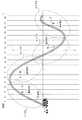
図6は、N=10人、n(k)=2人とした場合のシミュレーション結果である。図6によれば、最小の基地局数は26本であり、その計算時間に51分を要した。 FIG. 6 shows a simulation result when N = 10 people and n (k) = 2 people. According to FIG. 6, the minimum number of base stations is 26, and the calculation time required 51 minutes.
図7は、N=1人、n(k)=2人とした場合のシミュレーション結果である。図7によれば、最小の基地局数は10本であり、その計算時間に21分を要した。 FIG. 7 shows the simulation results when N = 1 and n (k) = 2. According to FIG. 7, the minimum number of base stations is 10, and the calculation time required 21 minutes.
図8は、N=1人、n(k)=1km毎に16人、それ以外の区間は0人(全96人)とした場合のシミュレーション結果である。図8によれば、最小の基地局数は11本であり、その計算時間に3分を要した。 FIG. 8 shows a simulation result when N = 1 person, 16 persons per n (k) = 1 km, and 0 persons (96 persons in total) in other sections. According to FIG. 8, the minimum number of base stations is 11, and the calculation time required 3 minutes.
図6〜8について、I=50区間とし、基地局が配置された区間には*が記載されている。また、---によって、1つの基地局がカバーする範囲が表されている。全てのqが7dB(5.012)以上となり、全ての区間において電車内の端末が要求する最低回線品質を満たしていることが把握できる。 6 to 8, I = 50 section, and * is described in the section where the base station is arranged. In addition, a range covered by one base station is represented by ---. All the q values are 7 dB (5.012) or more, and it can be understood that the minimum line quality required by the terminals in the train is satisfied in all sections.
前述した本発明における種々の実施形態によれば、本発明の技術思想及び見地の範囲の種々の変更、修正及び省略を、当業者は容易に行うことができる。前述の説明はあくまで例であって、何ら制約しようとするものではない。本発明は、特許請求の範囲及びその均等物として限定するものにのみ制約される。 According to the above-described various embodiments of the present invention, those skilled in the art can easily make various changes, modifications, and omissions in the technical idea and scope of the present invention. The above description is merely an example, and is not intended to be restrictive. The invention is limited only as defined in the following claims and the equivalents thereto.
1 電車
2 鉄道線路
3 基地局1
Claims (4)
Translated fromJapanese目的関数として、基地局数Σj=1If(j)を最小にするために、
制約条件として、
dist(i)≦|i-j+1|+α(1-f(j))、|i-j|≦α
Qは、電車内の端末が要求する最低回線品質(電力対雑音密度比)であり、
g(i,j)は、区間jに配置された基地局から区間iへの伝搬損失であり、
p(j)は、区間jに配置された基地局から1端末への送信電力であり、
n(k)は、区間kにおける同時接続端末数であり、
Nは、電車内の同時接続端末数であり、
Gは、拡散利得であり、
dist(i)は、区間iに存在する電車内の端末と接続する基地局との距離であり、
αは、基地局と端末とが接続可能な最大距離であり、
分子式は、区間iに存在する電車内の1端末が、区間jに配置された基地局から受信する所望波受信電力であり、
分母左辺式は、区間iに存在する電車内の1端末が受信する、電車外のトラヒックからの干渉電力の総和であり、
分母右辺式は、区間iに存在する電車内の1端末が受信する、電車内の他の端末のトラヒックからの干渉電力の総和であり、
となるように、線形計画法を用いて算出するステップを有するようにコンピュータを実行させることを特徴とするセル設計プログラム。A straight line from a predetermined start point to an end point on a railway track is divided into equally spaced sections i (I = 1 to I), and the base station arranged in section j is changed to section i for optimal placement of base stations. A cell design program for causing a computer to execute so as to determine whether or not h (i, j) (= 1,0) to accommodate an existing terminal,
In order to minimize the number of base stations Σj = 1I f (j) as an objective function,
As a constraint,
dist (i) ≦ | i-j + 1 | + α (1-f (j)), | ij | ≦ α
Q is the minimum line quality (power-to-noise density ratio) required by the terminal in the train.
g (i, j) is a propagation loss from the base station arranged in section j to section i,
p (j) is the transmission power from the base station arranged in section j to one terminal,
n (k) is the number of simultaneously connected terminals in section k,
N is the number of simultaneously connected terminals in the train,
G is the diffusion gain,
dist (i) is the distance from the base station connected to the terminal in the train existing in section i,
α is the maximum distance that the base station and the terminal can be connected,
The molecular formula is the desired wave received power that one terminal in the train existing in the section i receives from the base station arranged in the section j.
The denominator left-side expression is the sum of the interference power from traffic outside the train that is received by one terminal in the train that exists in section i.
The denominator right-hand side expression is the sum of interference power from traffic of other terminals in the train received by one terminal in the train existing in the section i,
A cell design program for causing a computer to have a step of calculating using linear programming.
目的関数として、基地局数Σ1If(j)を最小にするために、
制約条件として、
n(t,i)は、時間tについて区間iの基地局との同時接続端末数であり、
m(t)は、時間tについて電車内の端末が接続する基地局が存在する区間であり、
r(t、m(t))は、時間tについて電車内の1端末が、区間m(t)に存在する基地局から受信する電力であり、
分母式は、全ての基地局からの受信電力から、当該端末の前記所望波受信電力r(t,i)を差し引いた量であり、
となるように、線形計画法を用いて算出するステップを有するようにコンピュータを実行させることを特徴とするセル設計プログラム。Dividing the straight line from the predetermined start point to the end point on the railway track into equally spaced sections i (I = 1 to I), A cell design program that causes a computer to execute whether or not to arrange a base station f (j) (= 1,0) in a section i for optimal arrangement of base stations,
As an objective function, to the base station number sigma1I f the (j) to a minimum,
As a constraint,
n (t, i) is the number of simultaneously connected terminals with the base station in section i for time t,
m (t) is a section where a base station to which a terminal in the train is connected at time t exists,
r (t, m (t)) is the power received by one terminal in the train from the base station existing in the section m (t) at time t,
The denominator formula is an amount obtained by subtracting the desired wave received power r (t, i) of the terminal from the received power from all base stations,
A cell design program for causing a computer to have a step of calculating using linear programming.
Priority Applications (1)
| Application Number | Priority Date | Filing Date | Title |
|---|---|---|---|
| JP2005258004AJP4655836B2 (en) | 2005-09-06 | 2005-09-06 | Cell design program and apparatus for optimal placement of base stations on railroad tracks |
Applications Claiming Priority (1)
| Application Number | Priority Date | Filing Date | Title |
|---|---|---|---|
| JP2005258004AJP4655836B2 (en) | 2005-09-06 | 2005-09-06 | Cell design program and apparatus for optimal placement of base stations on railroad tracks |
Publications (2)
| Publication Number | Publication Date |
|---|---|
| JP2007074241A JP2007074241A (en) | 2007-03-22 |
| JP4655836B2true JP4655836B2 (en) | 2011-03-23 |
Family
ID=37935328
Family Applications (1)
| Application Number | Title | Priority Date | Filing Date |
|---|---|---|---|
| JP2005258004AExpired - Fee RelatedJP4655836B2 (en) | 2005-09-06 | 2005-09-06 | Cell design program and apparatus for optimal placement of base stations on railroad tracks |
Country Status (1)
| Country | Link |
|---|---|
| JP (1) | JP4655836B2 (en) |
Cited By (1)
| Publication number | Priority date | Publication date | Assignee | Title |
|---|---|---|---|---|
| CN109548034A (en)* | 2019-01-11 | 2019-03-29 | 中国联合网络通信集团有限公司 | A kind of method and device for disposing base station for high-speed rail |
Families Citing this family (4)
| Publication number | Priority date | Publication date | Assignee | Title |
|---|---|---|---|---|
| US8897269B2 (en) | 2008-01-30 | 2014-11-25 | Qualcomm Incorporated | Method and apparatus for mitigating pilot pollution in a wireless network |
| JP4944822B2 (en)* | 2008-03-25 | 2012-06-06 | 公益財団法人鉄道総合技術研究所 | Wireless LAN system |
| CN109714779B (en)* | 2017-10-25 | 2022-05-17 | 中国电信股份有限公司 | Network coverage identification method and device for railway |
| CN109842885A (en)* | 2019-01-03 | 2019-06-04 | 中国联合网络通信集团有限公司 | A kind of Equipments Choosing Method and device based on scene |
Family Cites Families (3)
| Publication number | Priority date | Publication date | Assignee | Title |
|---|---|---|---|---|
| JP3439396B2 (en)* | 1999-09-24 | 2003-08-25 | 日本電信電話株式会社 | Electromagnetic environment design method and recording medium storing design program |
| JP4819303B2 (en)* | 2002-10-23 | 2011-11-24 | 日本電気株式会社 | Base station installation design method, base station installation design apparatus and program in mobile communication system |
| JP2005081558A (en)* | 2003-09-04 | 2005-03-31 | Fuji Photo Film Co Ltd | Method and apparatus for manufacturing inkjet recording paper sheet |
- 2005
- 2005-09-06JPJP2005258004Apatent/JP4655836B2/ennot_activeExpired - Fee Related
Cited By (2)
| Publication number | Priority date | Publication date | Assignee | Title |
|---|---|---|---|---|
| CN109548034A (en)* | 2019-01-11 | 2019-03-29 | 中国联合网络通信集团有限公司 | A kind of method and device for disposing base station for high-speed rail |
| CN109548034B (en)* | 2019-01-11 | 2021-09-28 | 中国联合网络通信集团有限公司 | Method and device for deploying base station for high-speed rail |
Also Published As
| Publication number | Publication date |
|---|---|
| JP2007074241A (en) | 2007-03-22 |
Similar Documents
| Publication | Publication Date | Title |
|---|---|---|
| Qiu et al. | A methodology for studying 802.11 p VANET broadcasting performance with practical vehicle distribution | |
| Bu et al. | Performance improved methods for communication-based train control systems with random packet drops | |
| TW200629801A (en) | Wireless local area network radio resource management admission control | |
| Wen et al. | Access point deployment optimization in CBTC data communication system | |
| Sarker et al. | Connectivity maintenance for next-generation decentralized vehicle platoon networks | |
| TWI268342B (en) | System and method for planning route | |
| CN112465205A (en) | Single-line multi-station cooperative current limiting rail transit train running density optimization method | |
| JP4655836B2 (en) | Cell design program and apparatus for optimal placement of base stations on railroad tracks | |
| Sierpiński et al. | Use of GSM Technology as the Support to Manage the Modal Distribution in the Cities | |
| JP2018081650A (en) | Boarding guidance device, boarding guidance program, and boarding guidance method | |
| IL171825A (en) | Management of resources in a point-to-multipoint-or multipoint-to-multipoint-type communication network, using two allocation levels | |
| Gu et al. | Resource reservation coordination for vehicle platooning in c-v2x networks | |
| CN111859718A (en) | Method and system for calculating congestion coefficient of regional multi-standard rail transit station | |
| Kobayashi et al. | Vehicle mobility characterization based on measurements and its application to cellular communication systems | |
| Kuruvatti et al. | Mobility prediction of diurnal users for enabling context aware resource allocation | |
| Wen et al. | A practical access point deployment optimization strategy in communication-based train control systems | |
| Ferretti et al. | Enhancing LoRaWAN-Based Railway Signalling Systems for Secondary Lines: A Probabilistic Analysis of Multi-Hop Localization | |
| Sun et al. | Adaptive beaconing for collision avoidance and tracking accuracy in vehicular networks | |
| CN111931386B (en) | Method and system for calculating congestion coefficient of regional multi-standard rail traffic interval | |
| CN111859717B (en) | Method and system for minimizing regional multi-standard rail transit passenger congestion coefficient | |
| Schneps-Schneppe et al. | Mesh network for railways | |
| JPWO2020194698A1 (en) | Receiving terminal, transmission / reception system, wireless transmission device, reception method and transmission / reception method | |
| Sroka et al. | Distributed learning for vehicular dynamic spectrum access in autonomous driving | |
| Chen et al. | Park-and-ride network design in a bi-modal transport network to prompt public transport mode share | |
| CN113784308B (en) | Content sharing method and device based on coding cache |
Legal Events
| Date | Code | Title | Description |
|---|---|---|---|
| A621 | Written request for application examination | Free format text:JAPANESE INTERMEDIATE CODE: A621 Effective date:20080623 | |
| A131 | Notification of reasons for refusal | Free format text:JAPANESE INTERMEDIATE CODE: A131 Effective date:20100907 | |
| A521 | Request for written amendment filed | Free format text:JAPANESE INTERMEDIATE CODE: A523 Effective date:20101102 | |
| TRDD | Decision of grant or rejection written | ||
| A01 | Written decision to grant a patent or to grant a registration (utility model) | Free format text:JAPANESE INTERMEDIATE CODE: A01 Effective date:20101130 | |
| A01 | Written decision to grant a patent or to grant a registration (utility model) | Free format text:JAPANESE INTERMEDIATE CODE: A01 | |
| A61 | First payment of annual fees (during grant procedure) | Free format text:JAPANESE INTERMEDIATE CODE: A61 Effective date:20101213 | |
| FPAY | Renewal fee payment (event date is renewal date of database) | Free format text:PAYMENT UNTIL: 20140107 Year of fee payment:3 | |
| R150 | Certificate of patent or registration of utility model | Free format text:JAPANESE INTERMEDIATE CODE: R150 | |
| LAPS | Cancellation because of no payment of annual fees |