JP4655210B2 - Density correction curve generation method and density correction curve generation module - Google Patents
Density correction curve generation method and density correction curve generation moduleDownload PDFInfo
- Publication number
- JP4655210B2 JP4655210B2JP2005196341AJP2005196341AJP4655210B2JP 4655210 B2JP4655210 B2JP 4655210B2JP 2005196341 AJP2005196341 AJP 2005196341AJP 2005196341 AJP2005196341 AJP 2005196341AJP 4655210 B2JP4655210 B2JP 4655210B2
- Authority
- JP
- Japan
- Prior art keywords
- face
- density correction
- density
- correction coefficient
- dependent
- Prior art date
- Legal status (The legal status is an assumption and is not a legal conclusion. Google has not performed a legal analysis and makes no representation as to the accuracy of the status listed.)
- Expired - Fee Related
Links
Images


Landscapes
- Image Processing (AREA)
- Facsimile Image Signal Circuits (AREA)
- Image Analysis (AREA)
Description
Translated fromJapanese本発明は、顔領域を含む入力撮影画像の濃度補正に用いられる濃度補正曲線を生成する技術に関する。 The present invention relates to a technique for generating a density correction curve used for density correction of an input photographed image including a face area.
現在、写真プリント業界では、写真フィルムに形成された撮影画像をフィルムスキャナを用いてデジタル化して得られた撮影画像データや、デジタルカメラなどのデジタル撮影機器によって直接撮影画像をデジタル化して得られた撮影画像データに(以下単に撮影画像と略称する)濃度補正や色補正などの画像処理を施した後これをプリントデータに変換し、このプリントデータに基づいてプリント露光ユニットを駆動して、撮影画像を感光材料(印画紙)に焼き付けるデジタル写真処理技術が、主流である。 At present, in the photographic printing industry, it has been obtained by digitizing a photographed image data obtained by digitizing a photographed image formed on a photographic film using a film scanner or a digital photographing device such as a digital camera. The captured image data (hereinafter simply referred to as a captured image) is subjected to image processing such as density correction and color correction, then converted to print data, and the print exposure unit is driven based on the print data to capture the captured image. The mainstream is digital photographic processing technology that prints on a photosensitive material (photographic paper).
このようなデジタル写真処理技術の分野では、例えば、撮像素子により写真フィルムを測光して得られるコマごとのR(赤)・G(緑)・B(青)の撮影画像に基づいて画質の良好な画像を印画紙に焼き付けるため、入力された撮影画像の濃度を補正する処理が行われている。濃度補正方法としては、濃度補正曲線(ガンマ補正)による濃度補正が一般的である。つまり、入力撮影画像の濃度階調に対して印画紙が発色する濃度階調は一致しないので、印画紙が発色する濃度階調が人間の視覚特性に適したものになるように設定された濃度補正曲線を用いて入力画像データを補正し、この補正された出力画像データに基づいて最終的に得られる写真プリント(印画紙)上で発色している濃度階調が人間の視覚特性に応じたものになるようにしている。濃度補正曲線としては、理論的かつ経験的な知識に基づいて作成されたベースとなる濃度補正曲線がよく知られており、以前からこのようなベースとなる濃度補正曲線を濃度補正係数によって調整しながら用いられている。しかしながら、撮影画像の被写体状況や撮影環境状況は千差万別であり、単純に補正された濃度補正曲線では、入力された撮影画像データの撮像シーンによっては、適切な出力画像データを得られないという問題が生じている。例えば、オーバー/アンダー露出(露光過多/露光過少)で撮影された写真フィルムから取り込んだ撮影画像データを補正する場合は、撮影画像データを構成する各画素の輝度が低輝度(シャドウ部)または高輝度(ハイライト部)に偏り過ぎているのに対して、基本的な濃度補正曲線におけるシャドウ部およびハイライト部の傾斜率は緩やかになっているため、入力濃度に対して出力濃度が極めて弱くなるように補正されてしまう。とくに、撮影画像に人物画像、つまり顔領域が含まれている場合、顔領域の補正が適正に行われず、人物写真の品質を高めることは困難であった。 In the field of digital photographic processing technology, for example, good image quality is obtained based on R (red), G (green), and B (blue) captured images for each frame obtained by photometry of a photographic film with an image sensor. In order to print a simple image on photographic paper, a process for correcting the density of the input captured image is performed. As a density correction method, density correction by a density correction curve (gamma correction) is generally used. In other words, since the density gradation that the photographic paper develops does not match the density gradation of the input photographed image, the density gradation that the photographic paper develops is set to be suitable for human visual characteristics. The input image data is corrected using the correction curve, and the density gradation that is colored on the photographic print (printing paper) finally obtained based on the corrected output image data corresponds to the human visual characteristics. I try to be something. As a density correction curve, a base density correction curve created based on theoretical and empirical knowledge is well known, and such a base density correction curve is adjusted by a density correction coefficient. While being used. However, the subject situation and the shooting environment situation of the shot image are various, and appropriate output image data cannot be obtained depending on the shooting scene of the input shot image data with the simply corrected density correction curve. The problem has arisen. For example, when correcting photographic image data captured from photographic film taken with over / under exposure (overexposure / underexposure), the brightness of each pixel constituting the photographic image data is low (shadow) or high. The output density is very weak with respect to the input density because the slope of the shadow part and highlight part in the basic density correction curve is moderate, while the brightness (highlight part) is too biased. Will be corrected. In particular, when a photographed image includes a person image, that is, a face area, the face area is not properly corrected, and it is difficult to improve the quality of the person photograph.
そのような顔領域が含まれている人物撮影画像に対する適正な濃度補正を行うために、人物の肌色に相当する色相を有する画素のRGBデータの特徴量と人物が含まれている可能性の高い領域の画素のRGBデータの特徴量とに基づいて濃度補正曲線を修正することにより、人物の濃度が適正に補正されるように工夫されたものもある(特許文献1参照。)。この技術では、ある程度の確率をもって人物撮影画像の改善が得られるが、肌色画素が一義的に人物を規定するものではないので、被写体によっては不適当な濃度補正が施されることになる。 In order to perform appropriate density correction on a human photographed image including such a face area, it is highly likely that a person has a feature amount of RGB data of a pixel having a hue corresponding to the skin color of the person. Some have been devised so that the density of a person is appropriately corrected by correcting the density correction curve based on the feature values of the RGB data of the pixels in the region (see Patent Document 1). Although this technique can improve a person-photographed image with a certain degree of probability, the skin color pixels do not uniquely define a person, so that an inappropriate density correction is performed depending on the subject.
撮影画像データからオペレータが顔領域を指定して、その顔領域に基づいた濃度補正を行う技術も知られているが(例えば特許文献2、特許文献3参照。)、単純に人物の顔に濃度を合わせるような修正を基本濃度補正曲線に施して濃度補正した場合、人物の顔とそれ以外の背景とのバランスが崩れてしまって不自然な写真プリントを出力してしまうことも少なくない。 A technique is also known in which an operator designates a face area from captured image data and performs density correction based on the face area (see, for example, Patent Document 2 and Patent Document 3). When the density correction is performed by correcting the basic density correction curve so as to match, the balance between the human face and the other background is often lost and an unnatural photo print is output.
また、入力撮影画像から検出された顔領域の顔平均濃度値に基づいて生成された顔依存濃度特性曲線(顔依存濃度補正曲線)と基本濃度特性曲線(基本濃度補正曲線)との差から第1補正値を決定し、この第1補正値に基づいて基本濃度補正曲線を修正する技術も知られている(特許文献4参照。)。この従来技術では、最終的に濃度補正に用いられる濃度補正曲線が、基本濃度補正曲線と顔依存濃度補正曲線との間の調和のとれた特性をもつことができる場合に、良好な人物写真プリントを出力することができるが、高い信頼性をもって基本濃度補正曲線と顔依存濃度補正曲線との間の調和を図ることになお課題がある。 Further, the difference between the face-dependent density characteristic curve (face-dependent density correction curve) generated based on the face average density value of the face area detected from the input photographed image and the basic density characteristic curve (basic density correction curve) There is also known a technique for determining one correction value and correcting a basic density correction curve based on the first correction value (see Patent Document 4). In this prior art, when a density correction curve finally used for density correction can have a harmonious characteristic between a basic density correction curve and a face-dependent density correction curve, a good person photo print However, there is still a problem in achieving harmony between the basic density correction curve and the face-dependent density correction curve with high reliability.
上記実状に鑑み、本発明の課題は、基本濃度補正曲線と顔依存濃度補正曲線との間の調和を図ることで人物の顔を含む撮影画像に対して最適な濃度補正を施すことができる適正な濃度補正曲線を生成する技術を提供することである。 In view of the above situation, an object of the present invention is to make it possible to perform optimum density correction on a captured image including a human face by achieving harmony between a basic density correction curve and a face-dependent density correction curve. It is to provide a technique for generating a simple density correction curve.
上記課題を解決するために、顔領域を含む入力撮影画像の濃度補正に用いられる濃度補正曲線を生成するための濃度補正曲線生成方法において、本発明による方法は、前記入力撮影画像全体のヒストグラムから得られる代表値に基づいて基本濃度補正係数を決定するステップと、前記顔領域の平均濃度値である顔平均濃度値を算出するステップと、顔平均濃度と濃度補正係数の適正な関係を表す予め設定されたモデル式を用いて前記顔平均濃度値に対応する顔依存濃度補正係数を決定するステップと、前記基本濃度補正係数と前記顔依存補正係数とを比較してその適合度を評価するステップと、前記適合度に応じて前記顔依存補正係数を修正するステップと、修正された前記顔依存補正係数と前記基本濃度補正係数とを所定の融合率で融合して前記濃度補正曲線を生成するステップとからなる。 In order to solve the above problem, in a density correction curve generation method for generating a density correction curve used for density correction of an input photographed image including a face region, the method according to the present invention is based on a histogram of the entire input photographed image. A step of determining a basic density correction coefficient based on the obtained representative value, a step of calculating a face average density value that is an average density value of the face area, and an appropriate relationship between the face average density and the density correction coefficient in advance Determining a face-dependent density correction coefficient corresponding to the face average density value using the set model formula, and comparing the basic density correction coefficient and the face-dependent correction coefficient to evaluate their suitability A step of correcting the face-dependent correction coefficient in accordance with the fitness, and fusing the corrected face-dependent correction coefficient and the basic density correction coefficient at a predetermined fusion rate. Comprising a step of generating the density correction curve.
この濃度補正曲線生成方法では、顔平均濃度と濃度補正係数の適正な関係を表す予め設定されたモデル式を用いて、入力撮影画像における顔領域の顔平均濃度値に対応する顔依存濃度補正係数を決定し、この顔依存濃度補正係数を入力撮影画像全体のヒストグラムから得られる代表値に基づいて決定される基本濃度補正係数と比較してその適合度、つまり両者の相違度を評価して、その適合度に応じて顔依存濃度補正係数を撮影画像全体と顔領域との調和をできるだけ維持するように修正し、このように修正された顔依存補正係数と本来の基本濃度補正係数とを所定の融合率で融合して最終的に生成された濃度補正曲線を用いて入力撮影画像が濃度補正されるので、顔と背景との調和のとれた濃度補正が実現する。 In this density correction curve generation method, a face-dependent density correction coefficient corresponding to the face average density value of the face area in the input photographed image is used by using a preset model formula representing an appropriate relationship between the face average density and the density correction coefficient. This face-dependent density correction coefficient is compared with the basic density correction coefficient determined based on the representative value obtained from the histogram of the entire input photographed image, and its fitness, that is, the degree of difference between the two is evaluated. The face-dependent density correction coefficient is modified to maintain the harmony between the entire captured image and the face area as much as possible in accordance with the degree of fitness, and the face-dependent correction coefficient thus corrected and the original basic density correction coefficient are determined in advance. Since the input photographed image is subjected to density correction using the density correction curve finally generated by fusing at the fusion rate, density correction in harmony between the face and the background is realized.
顔領域を含む人物撮影画像においてその撮影シーンが逆光、順光、トップ光などによっても顔と背景との調和のしかたは異なってくる。このため、本発明による好適な実施形態の1つでは、前記顔依存補正係数が、前記顔領域と前記顔領域以外の入力撮影画像の濃度比較により決定される顔と背景の輝度バランスと入力撮影画像から得られる撮影シーン情報に基づいてさらに修正される。入力撮影画像から撮影シーン情報を得る方法は、濃度(輝度)の分布などから求めることができるが、入力撮影画像がその属性情報(exifデータなど)として撮影シーンに関する情報を有する場合は、それを利用することも可能である。 In a person-captured image including a face area, the manner in which the face and the background are harmonized also differs depending on whether the scene is backlit, forward light, top light, or the like. Therefore, in one preferred embodiment according to the present invention, the face-dependent correction coefficient is determined by comparing the density of the face area and the input captured image other than the face area, and the brightness balance between the face and the background and the input shooting. Further correction is made based on the shooting scene information obtained from the image. A method for obtaining shooting scene information from an input shot image can be obtained from a density (brightness) distribution or the like. If the input shot image has information about a shooting scene as its attribute information (exif data, etc.), It can also be used.
人物撮影におけるさらに特異な撮影シーンとして、顔領域にスポット光が存在しているようなシーンがあり、このようなシーンは顔領域の濃度分布から検知可能であるから、顔にスポット光が存在している確度であるスポット光存在度に応じて顔依存補正係数を修正あすることも好適な実施形態の1つとして提案される。 There is a scene where spot light exists in the face area as a more specific shooting scene in human photography. Since such a scene can be detected from the density distribution of the face area, there is spot light on the face. It is also proposed as one of the preferred embodiments to correct the face-dependent correction coefficient in accordance with the degree of presence of the spot light that is the certainty.
単に人物写真といっても、当然、全体に示す顔の割合によって顔の重要度が異なる。顔領域の示す割合が大きい撮影画像の場合、特に顔領域にできるだけ限定した濃度補正が要求される。このため、本発明の好適な実施形態の1つでは、前記入力撮影画像に占める前記顔領域の割合から前記融合率が調整されるように構成されている。 Naturally, even if it is simply a portrait, the importance of the face differs depending on the overall face ratio. In the case of a captured image in which the ratio indicated by the face area is large, density correction that is limited to the face area is required. For this reason, in one suitable embodiment of the present invention, it is constituted so that the fusion rate may be adjusted from the ratio of the face area to the input photographed image.
本発明では、上述した濃度補正曲線生成方法をコンピュータに実行させるプログラムやそのプログラムを記録した媒体も権利の対象とするものである。 In the present invention, a program for causing a computer to execute the above-described density correction curve generation method and a medium on which the program is recorded are also subject to rights.
さらに、本発明では、上述した濃度補正曲線生成方法を実施する濃度補正曲線生成モジュールも権利の対象としており、そのような濃度補正曲線生成モジュールは、入力撮影画像全体のヒストグラムから得られる代表値に基づいて基本濃度補正係数を決定する基本濃度補正係数決定部と、入力撮影画像に含まれている顔領域の平均濃度値である顔平均濃度値を算出する顔平均濃度算出部と、顔平均濃度と濃度補正係数の適正な関係を表す予め設定されたモデル式を用いて前記顔平均濃度値に対応する顔依存濃度補正係数を決定する顔依存濃度補正係数決定部と、前記基本濃度補正係数と前記顔依存補正係数とを比較してその適合度を評価するとともに前記適合度に応じて前記顔依存補正係数を修正する顔依存補正係数修正部と、修正された前記顔依存補正係数と前記基本濃度補正係数とを所定の融合率で融合して前記濃度補正曲線を生成する濃度補正曲線生成部とから構成されている。当然ながら、このような濃度補正曲線生成モジュールも上述した濃度補正曲線生成方法で述べたすべての作用効果を得ることができ、さらに上述した好適な実施形態を組み込むことも可能である。 Furthermore, in the present invention, a density correction curve generation module that implements the above-described density correction curve generation method is also subject to rights, and such a density correction curve generation module has a representative value obtained from a histogram of the entire input photographed image. A basic density correction coefficient determination unit that determines a basic density correction coefficient based on the image, a face average density calculation unit that calculates a face average density value that is an average density value of a face area included in the input captured image, and a face average density A face-dependent density correction coefficient determining unit that determines a face-dependent density correction coefficient corresponding to the face average density value using a preset model expression representing an appropriate relationship between the density correction coefficient and the basic density correction coefficient; A face-dependent correction coefficient correcting unit that compares the face-dependent correction coefficient and evaluates its suitability and modifies the face-dependent correction coefficient according to the suitability; The face dependent correction coefficient by fusing the basic density correction coefficient at a predetermined fusion rate is composed of a density correction curve generator for generating the density correction curve. Naturally, such a density correction curve generation module can also obtain all the effects described in the above-described density correction curve generation method, and can also incorporate the above-described preferred embodiment.
なお、顔依存補正係数と本来の基本濃度補正係数とを所定の融合率で融合して最終的な濃度補正曲線を生成するとの表現は、直接双方の補正係数を融合して最終的な濃度補正曲線を生成すること以外に、修正された顔依存補正係数によって規定される顔依存補正曲線と本来の基本濃度補正係数によって規定される基本濃度補正曲線とを所定の融合率で融合して最終的な濃度補正曲線を生成することも意味している。
また、ここで使われている濃度補正曲線なる用語は数学的な補正曲線に限定して解釈されるのではなく、その実体は、離散的な補正曲線であってもよいし、ソフトウエアにおいてよく用いられるテーブル化された抽出可能なデータ群で定義されるものであってもよいし、ソフトウエア的に又はハードウエア的にあるいはその両方の意味において入力濃度を出力濃度に変換する濃度特性を特定する全てのデータ構造体を意味するものである。
本発明によるその他の特徴及び利点は、以下図面を用いた実施形態の説明により明らかになるだろう。Note that the expression of fusing the face-dependent correction coefficient and the original basic density correction coefficient at a predetermined fusion rate to generate the final density correction curve is the result of directly fusing both correction coefficients and final density correction. In addition to generating a curve, the face-dependent correction curve defined by the modified face-dependent correction coefficient and the basic density correction curve defined by the original basic density correction coefficient are merged at a predetermined fusion rate, and finally It also means that a simple density correction curve is generated.
Also, the term density correction curve used here is not limited to a mathematical correction curve, but the entity may be a discrete correction curve or often used in software. It may be defined by the tabulated extractable data used, and it specifies a density characteristic that converts input density to output density in the sense of software and / or hardware. Means all data structures.
Other features and advantages of the present invention will become apparent from the following description of embodiments using the drawings.
本発明による、顔領域を含む撮影画像の濃度を補正する際に用いられる適正な濃度補正曲線を生成技術の実施形態について、図面に基づいて説明する。
図1は本発明による濃度補正曲線生成技術を採用した写真プリント装置を示す外観図であり、この写真プリント装置は、印画紙Pに対して露光処理と現像処理とを行う写真プリンタとしてのプリントステーション1Bと、現像済み写真フィルム2aやデジタルカメラ用メモリカード2bなどの画像入力メディアから取り込んだ撮影画像を処理してプリントステーション1Bで使用されるプリントデータの生成・転送などを行う操作ステーション1Aとから構成されている。An embodiment of a technique for generating an appropriate density correction curve used when correcting the density of a captured image including a face area according to the present invention will be described with reference to the drawings.
FIG. 1 is an external view showing a photographic printing apparatus employing a density correction curve generation technique according to the present invention. This photographic printing apparatus is a printing station as a photographic printer that performs exposure processing and development processing on photographic paper P. 1B and an
この写真プリント装置はデジタルミニラボとも称せられるものであり、図2からよく理解できるように、プリントステーション1Bは2つの印画紙マガジン11に納めたロール状の印画紙Pを引き出してシートカッター12でプリントサイズに切断すると共に、このように切断された印画紙Pに対し、バックプリント部13で色補正情報やコマ番号などのプリント処理情報を印画紙Pの裏面に印字するとともに、プリント露光部14で印画紙Pの表面に撮影画像の露光を行い、この露光後の印画紙Pを複数の現像処理槽を有した処理槽ユニット15に送り込んで現像処理する。乾燥の後に装置上部の横送りコンベア16からソータ17に送られた印画紙P、つまり写真プリントPは、このソータ17の複数のトレイにオーダ単位で仕分けられた状態で集積される(図1参照)。 This photo printing apparatus is also called a digital minilab. As can be understood from FIG. 2, the
上述した印画紙Pに対する各種処理に合わせた搬送速度で印画紙Pを搬送するために印画紙搬送機構18が敷設されている。印画紙搬送機構18は、印画紙搬送方向に関してプリント露光部14の前後に配置されたチャッカー式印画紙搬送ユニット18aを含む複数の挟持搬送ローラ対から構成されている。 A photographic
プリント露光部14には、副走査方向に搬送される印画紙Pに対して、主走査方向に沿って操作ステーション1Aからのプリントデータに基づいてR(赤)、G(緑)、B(青)の3原色のレーザ光線の照射を行うライン露光ヘッドが設けられている。処理槽ユニット15は、発色現像処理液を貯留する発色現像槽15aと、漂白定着処理液を貯留する漂白定着槽15bと、安定処理液を貯留する安定槽15cを備えている。 The
前記操作ステーション1Aのデスク状コンソールの上部位置には、写真フィルム2aの撮影画像コマから撮影画像データ(以下単に画像データと略称する)を取得するフィルムスキャナ20が配置されており、デジタルカメラ等に装着される撮影画像記録媒体2bとして用いられている各種半導体メモリやCD−Rなどから画像データとしての撮影画像を取得するメディアリーダ21は、この写真プリント装置のコントローラ3として機能する汎用パソコンに組み込まれている。この汎用パソコンには、さらに各種情報を表示するモニタ23、各種設定や調整を行う際に用いる操作入力部として利用されるポインティングデバイスとしてのキーボード24やマウス25も接続されている。 A
この写真プリント装置のコントローラ3は、CPUを中核部材として、写真プリント装置の種々の動作を行うための機能部をハードウエア又はソフトウエアあるいはその両方で構築しているが、図3に示されているように、本発明に特に関係する機能部としては、スキャナ20やメディアリーダ21によって読み取られた撮影画像を取り込んで次の処理のために必要な前処理を行う画像入力部31と、各種ウインドウや各種操作ボタンなどを含むグラフィック操作画面の作成やそのようなグラフィック操作画面を通じてのユーザ操作入力(キーボード24やマウス25などによる)から制御コマンドを生成するグラフィックユーザインターフェース(以下GUIと略称する)を構築するGUI部33と、GUI部33から送られてきた制御コマンドや直接キーボード24等から入力された操作命令に基づいて所望のプリントデータを生成するために画像入力部31からメモリ30に転送された撮影画像に対する濃度補正や色補正さらにはフォトレタッチ処理等を行う画像管理部32と、色補正等のプレジャッジプリント作業時にプリントソース画像や予想仕上がりプリント画像としてのシミュレート画像さらにはGUI部33から送られてきたグラフィックデータをモニタ23に表示させるためのビデオ信号を生成するビデオ制御部35と、画像処理が完了した処理済み画像データに基づいてプリントステーション1Bに装備されているプリント露光部14に適したプリントデータを生成するプリントデータ生成部36と、顧客の要望に応じて元の撮影画像や画像処理が完了した撮影画像を画像データとしてCD−Rに書き込むための形式にフォーマットするフォーマッタ部37などが挙げられる。 The controller 3 of this photographic printing apparatus uses a CPU as a core member and constructs a functional unit for performing various operations of the photographic printing apparatus by hardware and / or software, as shown in FIG. As described above, the functional unit particularly related to the present invention includes an
画像入力部31は、撮影画像記録媒体がフィルム2aの場合プレスキャンモードと本スキャンモードとのスキャンデータを別々にメモリ30に送り込み、それぞれの目的に合わせた前処理を行う。また、撮影画像記録媒体がメモリカード2bの場合取り込んだ撮影画像の画像データにサムネイル画像データ(低解像度データ)が含まれている場合はこのデータをモニタ23での一覧表示などの目的で使用するため撮影画像の本データ(高解像度データ)とは別にメモリ30に送り込むが、もしサムネイル画像データが含まれていない場合は本データから縮小画像を作り出して低解像度画像データとしてメモリ30に送り込む。 When the photographic image recording medium is the
画像管理部32は、メモリ30に展開された低解像度の撮影画像から顔検出アルゴリズムを用いて検出された顔領域の位置やサイズを含む顔検出情報を出力する顔検出モジュール40、メモリ30に展開された高解像度の撮影画像に対して濃度補正を施す濃度補正モジュール50、この濃度補正モジュール50が濃度補正処理の際に用いる濃度補正曲線を撮影画像に含まれている顔領域の特性に基づいて適正に生成する濃度補正曲線生成モジュール60、濃度補正された撮影画像に対して色補正やフィルタリング(ぼかしやシャープネスなど)などの画像処理を施す画像処理モジュール70を備えている。 The
顔検出モジュール40は汎用的なものを使用することが可能であり、ここでは、顔検出アルゴリズムに基づいて撮影画像中の顔と見なされる領域を検出し、その顔位置やサイズ(顔位置を基点とした矩形画素領域の縦横サイズ)などの顔検出情報を出力するものが使われている。画像データから顔を検出する顔検出アルゴリズムは数多く知られているが、例えば、特開平11−339084号公報、特開2000−99722号公報、特開2000−22929号公報が参照される。また、この顔検出を自動的に行うのではなく、オペレータによって手動で行ってもよく、この場合顔検出モジュール40は顔検出アルゴリズムを持たず、オペレータの操作入力に基づく顔検出情報を出力するだけの構成となる。 The
図4に示すように、濃度補正モジュール50は、濃度補正曲線を撮影画像の画像特性に基づいて濃度補正曲線生成モジュール60によって設定調整された適正な濃度補正曲線を設定格納している濃度補正曲線テーブル52を用いて高解像度の撮影画像に対する濃度補正を実行する濃度補正部51からなる。一般的に、濃度補正部51はプログラムによって実現されており、濃度補正曲線テーブル52はルックアップテーブルといったデータ構造体によって実現されるが、本発明はこれに限定しているわけではない。 As shown in FIG. 4, the
同様に濃度補正曲線生成モジュール60も、プログラムによって実現されている。この濃度補正曲線生成モジュール60は、図4に示すように、基本濃度補正係数決定部61、顔領域設定部62、顔平均濃度算出部63、モデル式格納部64、顔依存濃度補正係数決定部65、顔依存濃度補正係数修正部66、濃度補正曲線生成部67、融合率設定部68、撮影シーン評価部69を備えている。 Similarly, the density correction
基本濃度補正係数決定部61は、入力された撮影画像の統計学的代表値、例えば撮影画像全体のヒストグラムから得られる最小値、最大値、平均値などをパラメータとして基本濃度係数を決定する。この基本濃度係数は基本濃度補正曲線を規定するものであり、予め定められている基準となる濃度変換特性(形状)を有する濃度補正曲線をベースとして、基本濃度係数に応じて変化することで入力された撮影画像に適した基本濃度補正曲線が決定される。 The basic density correction
顔領域設定部62は、顔検出モジュール40から出力された顔検出情報によって規定される入力撮影画像における顔領域位置からそのアドレス情報を求め、顔領域の画素を取り扱う処理部に顔領域の画像データ(画素値)を転送する。顔平均濃度算出部63は、顔領域設定部62からの転送データに基づいて顔領域(単一でも複数でもよい)の平均濃度値を算出する。この輝度を表現することにもなる平均濃度値の演算のために、ここでは各画素を構成するR・G・B濃度値の算術平均値を平均演算要素としてさらに顔領域全体を算術平均することにより算出している。もちろん、それ以外の平均濃度値の算出として、例えばR・G・B濃度値から輝度・色差値Y・C・Cに変換された輝度Yを用いて顔平均輝度(濃度)算出してもよい。つまり、ここでは、平均濃度値:(R+G+B)/3は、Y・C・C信号における輝度:Yと同様に扱われるものであり、本願での平均濃度値なる用語には平均輝度(Y)値も含まれている。 The face
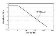
顔依存濃度補正係数決定部65は、モデル式格納部64に格納されているモデル式を用いて顔平均濃度値から顔依存濃度補正係数を決定するものであり、このモデル式は、種々の撮影条件下で取得された多数の撮影画像をサンプルとし、各サンプルの顔平均濃度値と濃度補正係数の分布を考察することによって得られた、顔平均濃度値と適正な顔領域を含む撮影画像に変換することができる濃度補正係数としての顔依存濃度補正係数との関係を示す関係式である。このモデル式によって表されるグラフの一例が図5に示されている。図5では、このモデル式は、顔平均濃度値をFave、顔依存濃度補正係数をγfとして、γf=M(Fave)で示されており、顔依存濃度補正係数が、顔平均濃度値の低域では高いレベルで変動が少なく、顔平均濃度値の高域では低いレベルで変動が少なく、顔平均濃度値の中間域では前記高いレベルから前記低いレベルに減少する特性を有している。 The face-dependent density correction
顔依存濃度補正係数決定部65によって決定された顔依存濃度補正係数と、基本濃度補正係数決定部61によって決定された基本濃度補正係数がほぼ等しければ、どちらの濃度補正係数を使っても作成される濃度補正曲線に実質的な違いがないので問題はないが、ある程度以上の差があると、顔依存濃度補正係数を修正しておく必要がある。例えば、顔領域の輝度が高いにもかかわらずその顔領域の画素をさらに明るくするような特性を示す濃度補正係数ならば、顔領域の画素を明るくしないような方向に顔依存濃度補正係数を修正する必要がある。このような顔依存濃度補正係数と基本濃度補正係数との間の適合度(相違度)に基づく修正が、顔依存濃度補正係数修正部66によって行われる。 If the face-dependent density correction coefficient determined by the face-dependent density correction
この濃度補正曲線生成部67は、顔依存濃度補正係数修正部66から出力された顔依存濃度補正係数と基本濃度補正係数決定部61から出力された基本濃度補正係数とを融合率設定部68で設定された融合率を用いて融合して最終的に濃度補正に用いられる適正な濃度補正曲線を生成するが、顔依存濃度補正係数修正部66から出力された顔依存濃度補正係数によって規定される顔依存濃度補正曲線と基本濃度補正係数決定部61から出力された基本濃度補正係数によって規定される基本濃度補正曲線を融合率設定部68で設定された融合率を用いて融合して最終的に濃度補正に用いられる適正な濃度補正曲線を生成するとも表現できる。融合率設定部68は、例えば、入力撮影画像に占める顔領域の割合が大きいほど顔依存濃度補正曲線に重みをおくように融合率を設定すると好都合である。 The density correction
撮影シーン評価部69は、顔領域と顔領域以外の入力撮影画像の濃度比較により逆光シーン度を決定したり、顔領域の濃度分布から顔領域におけるスポット光の存在強度を示すスポット光存在度を決定したりするものであり、この撮影シーン評価部69によって評価された撮影シーン情報に応じて、顔依存濃度補正係数修正部66が顔依存補正係数を修正することで、さらに顔依存濃度補正係数の精度が向上する。また、撮影シーン評価部69は、Exifデータなどから撮影シーン情報を取得することも可能である。 The shooting
上述したような濃度補正曲線生成モジュールによる濃度補正曲線生成の典型的な処理の流れを図6のフローチャートを用いて説明する。
撮影画像が入力されると(#01)、この入力撮影画像に対して顔検出モジュール40による顔検出処理(#02)と、基本濃度補正係数決定部61による基本濃度補正係数決定処理(#03)とが実行される。入力撮影画像に顔領域が含まれていない場合(#04No分岐)、従来通りに、基本濃度補正係数を用いて基本濃度補正曲線が生成され(#05)、この基本濃度補正曲線を最終的な濃度補正曲線として濃度補正処理が実行される(#20)。A typical process flow of density correction curve generation by the density correction curve generation module as described above will be described with reference to the flowchart of FIG.
When a captured image is input (# 01), a face detection process (# 02) by the
入力撮影画像に顔領域が含まれている場合(#04Yes分岐)、顔領域の平均濃度を顔平均濃度算出部が顔平均濃度値として算出する(#06)。顔平均濃度値が算出されると、顔依存濃度補正係数決定部65が、図5に示すようなモデル式(関係式)を用いてこの顔平均濃度値に適応する濃度補正係数(ガンマ係数)としての顔依存濃度補正係数を決定する(#07)。ここで、基本濃度補正係数決定部61によって決定された基本濃度補正係数と顔依存濃度補正係数決定部65によって決定された顔依存濃度補正係数を比較して大きな違いがないかどうか、つまり決定された顔依存濃度補正係数が基本濃度補正係数に適合しているかどうかの適合度が評価される(#08)。その適合度が許容範囲に入っており顔依存濃度補正係数が適切であるかどうか判定される(#09)。適合度の評価においては、単純な数値の比較以外に、例えば、元々の顔領域の輝度が高いにもかかわらず、顔依存濃度補正係数がさらに明るくなるような補正を示している場合その適合度が低く不適切であるといった評価判定もなされる。ステップ#09の適合度の判定で不適切とみなされた場合、通常基本濃度補正係数に近づく方向に顔依存濃度補正係数を補正する(#10)。 When a face area is included in the input captured image (# 04 Yes branch), the face area average density calculation unit calculates the average density of the face area as the face average density value (# 06). When the face average density value is calculated, the face-dependent density correction
続いて、顔と背景とのバランスを考慮した修正が必要かどうか判定される(#11)。例えば、逆光シーンではないが背景に白っぽく明るいものが存在しているとともに顔の輝度が低い場合その顔依存濃度補正係数が顔を過剰に明るくすることにならないような修正が必要であるし、逆光シーンである可能性が高い場合その顔依存濃度補正係数が顔を過剰に明るくするものであることが好ましいことになる。また、顔領域にスポット光が存在しているようなシーンがあり、このようなシーンは顔領域の濃度分布から検知可能であるから、顔にスポット光が存在している確度であるスポット光存在度に応じて顔依存補正係数を修正する必要があるかどうかも判定される。顔領域にスポット光が存在している場合にはそのようなスポット光に過剰に影響されない濃度補正が重要である。いずれにせよ、そのような顔と背景とのバランスを考慮した修正が必要な場合だけさらに顔依存濃度補正係数をわずかに修正する(#12)。なお、逆光シーンなどの撮影シーンに関する情報は撮影シーン評価部69から得ることができる。 Subsequently, it is determined whether or not correction in consideration of the balance between the face and the background is necessary (# 11). For example, if a scene is not a backlight scene but is white and bright and the face brightness is low, the face-dependent density correction coefficient must be corrected so that the face does not become excessively bright. When there is a high possibility of being a scene, it is preferable that the face-dependent density correction coefficient makes the face excessively bright. Also, there are scenes where spot light exists in the face area, and such scenes can be detected from the density distribution of the face area, so there is spot light presence that is the probability that spot light exists on the face. It is also determined whether the face-dependent correction coefficient needs to be corrected according to the degree. When spot light is present in the face area, density correction that is not excessively affected by such spot light is important. In any case, the face-dependent density correction coefficient is further slightly corrected only when such correction considering the balance between the face and the background is necessary (# 12). Information relating to a shooting scene such as a backlight scene can be obtained from the shooting
修正のあるなしにかかわらず最終的な顔依存濃度補正係数が決定されると、この顔依存濃度補正係数と基本濃度補正係数とが融合率設定部68によって設定された融合率で融合され、その融合された融合補正係数によって最終的な濃度補正曲線が生成される。このことを濃度補正曲線の融合という観点から表現すると、最終的に決定された顔依存濃度補正係数で規定される顔依存濃度補正曲線と、基本濃度補正係数で規定される基本濃度補正曲線が濃度補正曲線生成部67で生成される(#13)、生成された顔依存濃度補正曲線と基本濃度補正曲線は融合率設定部68によって設定された融合率(#14)で最終的な濃度補正曲線に融合される(#15)、ということになる。 When the final face-dependent density correction coefficient is determined regardless of whether the correction is made or not, the face-dependent density correction coefficient and the basic density correction coefficient are fused at the fusion rate set by the fusion
続いて、この最終的な基本濃度補正曲線として濃度補正処理が実行される(#20)。なお、融合率設定部68による融合率の設定は、入力撮影画像に占める顔領域の割合に基づいて、つまり顔領域の占有率が高いほど顔依存濃度補正曲線の重みが大きくなるように設定することが好都合である。もちろん、融合率設定部68が予め求められている一定の融合率を設定するようにしてもよい。 Subsequently, density correction processing is executed as the final basic density correction curve (# 20). Note that the fusion rate is set by the fusion
上述した実施の形態では、プリントステーション1Bは、印画紙Pに対し、露光エンジンを備えたプリント露光部14で撮影画像の露光を行い、この露光後の印画紙Pを複数の現像処理する、いわゆる銀塩写真プリント方式を採用していたが、もちろん、本発明による濃度補正曲線決定技術を用いているプリントステーション1Bは、このような方式に限定されるわけではなく、例えば、フィルムや紙にインクを吐出して画像を形成するインクジェットプリント方式や感熱転写シートを用いた熱転写方式など、種々の写真プリント方式を採用可能である。 In the above-described embodiment, the
30:メモリ
40:顔検出モジュール
50:濃度補正モジュール
51:濃度補正部
52:濃度補正曲線テーブル
60:濃度補正曲線生成モジュール
61:基本濃度補正係数決定部
62:顔領域設定部
63:顔平均濃度算出部
64:モデル式格納部
65:顔依存濃度補正係数決定部
66:顔依存濃度補正係数修正部
67:濃度補正曲線生成部
68:融合率設定部
69:撮影シーン評価部
30: Memory 40: Face detection module 50: Density correction module 51: Density correction unit 52: Density correction curve table 60: Density correction curve generation module 61: Basic density correction coefficient determination unit 62: Face area setting unit 63: Face average density Calculation unit 64: Model formula storage unit 65: Face-dependent density correction coefficient determination unit 66: Face-dependent density correction coefficient correction unit 67: Density correction curve generation unit 68: Fusion rate setting unit 69: Shooting scene evaluation unit
Claims (6)
Translated fromJapanese前記入力撮影画像全体のヒストグラムから得られる代表値に基づいて基本濃度補正係数を決定するステップと、
前記顔領域の平均濃度値である顔平均濃度値を算出するステップと、
顔平均濃度と濃度補正係数の適正な関係を表す予め設定されたモデル式を用いて前記顔平均濃度値に対応する顔依存濃度補正係数を決定するステップと、
前記基本濃度補正係数と前記顔依存補正係数とを比較してその適合度を評価するステップと、
前記適合度に応じて前記顔依存補正係数を修正するステップと、
修正された前記顔依存補正係数と前記基本濃度補正係数とを所定の融合率で融合して前記濃度補正曲線を生成するステップと、
からなることを特徴とする濃度補正曲線生成方法。In a density correction curve generation method for generating a density correction curve used for density correction of an input photographed image including a face area,
Determining a basic density correction coefficient based on a representative value obtained from a histogram of the entire input photographed image;
Calculating a face average density value which is an average density value of the face region;
Determining a face-dependent density correction coefficient corresponding to the face average density value using a preset model formula representing an appropriate relationship between the face average density and the density correction coefficient;
Comparing the basic density correction coefficient with the face-dependent correction coefficient and evaluating its fitness;
Modifying the face-dependent correction coefficient according to the fitness,
Fusing the modified face-dependent correction coefficient and the basic density correction coefficient at a predetermined fusion rate to generate the density correction curve;
A density correction curve generation method comprising:
前記入力撮影画像全体のヒストグラムから得られる代表値に基づいて基本濃度補正係数を決定する基本濃度補正係数決定部と、
前記顔領域の平均濃度値である顔平均濃度値を算出する顔平均濃度算出部と、
顔平均濃度と濃度補正係数の適正な関係を表す予め設定されたモデル式を用いて前記顔平均濃度値に対応する顔依存濃度補正係数を決定する顔依存濃度補正係数決定部と、
前記基本濃度補正係数と前記顔依存補正係数とを比較してその適合度を評価するとともに前記適合度に応じて前記顔依存補正係数を修正する顔依存補正係数修正部と、
修正された前記顔依存補正係数と前記基本濃度補正係数とを所定の融合率で融合して前記濃度補正曲線を生成する濃度補正曲線生成部とからなることを特徴とする濃度補正曲線生成モジュール。In a density correction curve generation module for generating a density correction curve used for density correction of an input captured image including a face area,
A basic density correction coefficient determination unit that determines a basic density correction coefficient based on a representative value obtained from a histogram of the entire input photographed image;
A face average density calculating unit that calculates a face average density value that is an average density value of the face region;
A face-dependent density correction coefficient determination unit that determines a face-dependent density correction coefficient corresponding to the face average density value using a preset model formula that represents an appropriate relationship between the face average density and the density correction coefficient;
Comparing the basic density correction coefficient and the face-dependent correction coefficient to evaluate their suitability and correcting the face-dependent correction coefficient according to the suitability;
A density correction curve generation module comprising: a density correction curve generation unit that generates the density correction curve by fusing the corrected face-dependent correction coefficient and the basic density correction coefficient at a predetermined fusion rate.
Priority Applications (1)
| Application Number | Priority Date | Filing Date | Title |
|---|---|---|---|
| JP2005196341AJP4655210B2 (en) | 2005-07-05 | 2005-07-05 | Density correction curve generation method and density correction curve generation module |
Applications Claiming Priority (1)
| Application Number | Priority Date | Filing Date | Title |
|---|---|---|---|
| JP2005196341AJP4655210B2 (en) | 2005-07-05 | 2005-07-05 | Density correction curve generation method and density correction curve generation module |
Publications (2)
| Publication Number | Publication Date |
|---|---|
| JP2007018073A JP2007018073A (en) | 2007-01-25 |
| JP4655210B2true JP4655210B2 (en) | 2011-03-23 |
Family
ID=37755213
Family Applications (1)
| Application Number | Title | Priority Date | Filing Date |
|---|---|---|---|
| JP2005196341AExpired - Fee RelatedJP4655210B2 (en) | 2005-07-05 | 2005-07-05 | Density correction curve generation method and density correction curve generation module |
Country Status (1)
| Country | Link |
|---|---|
| JP (1) | JP4655210B2 (en) |
Families Citing this family (6)
| Publication number | Priority date | Publication date | Assignee | Title |
|---|---|---|---|---|
| JP4934326B2 (en)* | 2005-09-29 | 2012-05-16 | 富士フイルム株式会社 | Image processing apparatus and processing method thereof |
| JP4823979B2 (en)* | 2007-07-23 | 2011-11-24 | 富士フイルム株式会社 | Image processing apparatus and method, and program |
| JP4906627B2 (en)* | 2007-07-31 | 2012-03-28 | キヤノン株式会社 | Image processing apparatus, image processing method, computer program, and storage medium |
| JP4600448B2 (en) | 2007-08-31 | 2010-12-15 | カシオ計算機株式会社 | Gradation correction apparatus, gradation correction method, and program |
| JP4525719B2 (en) | 2007-08-31 | 2010-08-18 | カシオ計算機株式会社 | Gradation correction apparatus, gradation correction method, and program |
| JP5031877B2 (en)* | 2010-01-06 | 2012-09-26 | キヤノン株式会社 | Image processing apparatus and image processing method |
Family Cites Families (6)
| Publication number | Priority date | Publication date | Assignee | Title |
|---|---|---|---|---|
| JPH06103927B2 (en)* | 1989-10-25 | 1994-12-14 | 大日本スクリーン製造株式会社 | Tone curve setting method |
| JP2682753B2 (en)* | 1991-03-14 | 1997-11-26 | 富士写真フイルム株式会社 | Pictorial hard copy device |
| JP3378601B2 (en)* | 1993-01-14 | 2003-02-17 | 三洋電機株式会社 | Image processing device |
| JP4057147B2 (en)* | 1998-06-16 | 2008-03-05 | コニカミノルタビジネステクノロジーズ株式会社 | Backlight scene determination method, computer-readable storage medium storing a backlight scene determination method program, and image processing apparatus having a backlight scene determination function |
| JP4415488B2 (en)* | 2000-12-14 | 2010-02-17 | ノーリツ鋼機株式会社 | Image forming apparatus, image data processing method, and recording medium recording image data processing program |
| JP2005159387A (en)* | 2003-11-20 | 2005-06-16 | Noritsu Koki Co Ltd | Method for determining density characteristic curve and density correction management apparatus for implementing this method |
- 2005
- 2005-07-05JPJP2005196341Apatent/JP4655210B2/ennot_activeExpired - Fee Related
Also Published As
| Publication number | Publication date |
|---|---|
| JP2007018073A (en) | 2007-01-25 |
Similar Documents
| Publication | Publication Date | Title |
|---|---|---|
| JP4780374B2 (en) | Image processing method and program for suppressing granular noise, and granular suppression processing module for implementing the method | |
| JP2005141477A (en) | Image sharpening processing method and image processing apparatus for implementing the method | |
| JP4496465B2 (en) | Red-eye correction method, program, and apparatus for implementing the method | |
| JP4655210B2 (en) | Density correction curve generation method and density correction curve generation module | |
| JP4798446B2 (en) | Photographed image correction method and photographed image correction module | |
| JP4591784B2 (en) | Method for creating conversion table for photographed image correction and photo printing apparatus for implementing this method | |
| JP2005148915A (en) | Appropriate face discrimination method and apparatus for carrying out this method | |
| JP4366634B2 (en) | Noise pixel map creation method, apparatus and program for implementing the method, and photo print apparatus | |
| JP2005159387A (en) | Method for determining density characteristic curve and density correction management apparatus for implementing this method | |
| JP4441853B2 (en) | Face selection method for density correction and apparatus for carrying out this method | |
| JP4441876B2 (en) | Photographed image processing method, photographed image processing program, and photographed image processing apparatus | |
| JP4731202B2 (en) | Color correction processing method and color correction processing apparatus using the same | |
| JP4284604B2 (en) | Contrast adjustment method and contrast adjustment apparatus for implementing the method | |
| JP2009004887A (en) | Image correction method and image correction apparatus | |
| JP2009027254A (en) | Image correction method and image correction apparatus | |
| JP4793648B2 (en) | Image correction unit and image correction program | |
| JP4655211B2 (en) | Generation method, generation program and generation module of correction characteristics used for contrast correction | |
| JP2004297439A (en) | Image correction method, apparatus, and program | |
| JP2006072743A (en) | Catchlight synthesis method and apparatus | |
| JP2008160704A (en) | Density correction curve generation method and density correction curve generation module | |
| JP2008153756A (en) | Density correction curve generation method and density correction curve generation module | |
| JP2006059162A (en) | Tooth image correction method and apparatus | |
| JP4835900B2 (en) | Image processing method and image processing apparatus for image data from a digital camera | |
| JP2008079196A (en) | Image correction method, image correction program, and image correction module | |
| JP2008306365A (en) | Image correction method and image correction apparatus |
Legal Events
| Date | Code | Title | Description |
|---|---|---|---|
| A621 | Written request for application examination | Free format text:JAPANESE INTERMEDIATE CODE: A621 Effective date:20080317 | |
| A977 | Report on retrieval | Free format text:JAPANESE INTERMEDIATE CODE: A971007 Effective date:20101117 | |
| TRDD | Decision of grant or rejection written | ||
| A01 | Written decision to grant a patent or to grant a registration (utility model) | Free format text:JAPANESE INTERMEDIATE CODE: A01 Effective date:20101125 | |
| A01 | Written decision to grant a patent or to grant a registration (utility model) | Free format text:JAPANESE INTERMEDIATE CODE: A01 | |
| A61 | First payment of annual fees (during grant procedure) | Free format text:JAPANESE INTERMEDIATE CODE: A61 Effective date:20101208 | |
| FPAY | Renewal fee payment (event date is renewal date of database) | Free format text:PAYMENT UNTIL: 20140107 Year of fee payment:3 | |
| R150 | Certificate of patent or registration of utility model | Ref document number:4655210 Country of ref document:JP Free format text:JAPANESE INTERMEDIATE CODE: R150 Free format text:JAPANESE INTERMEDIATE CODE: R150 | |
| S111 | Request for change of ownership or part of ownership | Free format text:JAPANESE INTERMEDIATE CODE: R313111 | |
| FPAY | Renewal fee payment (event date is renewal date of database) | Free format text:PAYMENT UNTIL: 20140107 Year of fee payment:3 | |
| R350 | Written notification of registration of transfer | Free format text:JAPANESE INTERMEDIATE CODE: R350 | |
| R250 | Receipt of annual fees | Free format text:JAPANESE INTERMEDIATE CODE: R250 | |
| R250 | Receipt of annual fees | Free format text:JAPANESE INTERMEDIATE CODE: R250 | |
| R250 | Receipt of annual fees | Free format text:JAPANESE INTERMEDIATE CODE: R250 | |
| S533 | Written request for registration of change of name | Free format text:JAPANESE INTERMEDIATE CODE: R313533 | |
| R350 | Written notification of registration of transfer | Free format text:JAPANESE INTERMEDIATE CODE: R350 | |
| R250 | Receipt of annual fees | Free format text:JAPANESE INTERMEDIATE CODE: R250 | |
| R250 | Receipt of annual fees | Free format text:JAPANESE INTERMEDIATE CODE: R250 | |
| R250 | Receipt of annual fees | Free format text:JAPANESE INTERMEDIATE CODE: R250 | |
| R250 | Receipt of annual fees | Free format text:JAPANESE INTERMEDIATE CODE: R250 | |
| R250 | Receipt of annual fees | Free format text:JAPANESE INTERMEDIATE CODE: R250 | |
| R250 | Receipt of annual fees | Free format text:JAPANESE INTERMEDIATE CODE: R250 | |
| R250 | Receipt of annual fees | Free format text:JAPANESE INTERMEDIATE CODE: R250 | |
| R250 | Receipt of annual fees | Free format text:JAPANESE INTERMEDIATE CODE: R250 | |
| LAPS | Cancellation because of no payment of annual fees |