JP4654484B2 - Fuel cell system and electric vehicle - Google Patents
Fuel cell system and electric vehicleDownload PDFInfo
- Publication number
- JP4654484B2 JP4654484B2JP2000120830AJP2000120830AJP4654484B2JP 4654484 B2JP4654484 B2JP 4654484B2JP 2000120830 AJP2000120830 AJP 2000120830AJP 2000120830 AJP2000120830 AJP 2000120830AJP 4654484 B2JP4654484 B2JP 4654484B2
- Authority
- JP
- Japan
- Prior art keywords
- fuel cell
- load
- cell system
- power
- power supply
- Prior art date
- Legal status (The legal status is an assumption and is not a legal conclusion. Google has not performed a legal analysis and makes no representation as to the accuracy of the status listed.)
- Expired - Fee Related
Links
Images


Classifications
- Y—GENERAL TAGGING OF NEW TECHNOLOGICAL DEVELOPMENTS; GENERAL TAGGING OF CROSS-SECTIONAL TECHNOLOGIES SPANNING OVER SEVERAL SECTIONS OF THE IPC; TECHNICAL SUBJECTS COVERED BY FORMER USPC CROSS-REFERENCE ART COLLECTIONS [XRACs] AND DIGESTS
- Y02—TECHNOLOGIES OR APPLICATIONS FOR MITIGATION OR ADAPTATION AGAINST CLIMATE CHANGE
- Y02E—REDUCTION OF GREENHOUSE GAS [GHG] EMISSIONS, RELATED TO ENERGY GENERATION, TRANSMISSION OR DISTRIBUTION
- Y02E60/00—Enabling technologies; Technologies with a potential or indirect contribution to GHG emissions mitigation
- Y02E60/30—Hydrogen technology
- Y02E60/50—Fuel cells
Landscapes
- Arrangement Or Mounting Of Propulsion Units For Vehicles (AREA)
- Electric Propulsion And Braking For Vehicles (AREA)
- Fuel Cell (AREA)
Description
Translated fromJapanese【0001】
【発明の属する技術分野】
本発明は、燃料電池システムおよび電気自動車に関し、詳しくは燃料電池と2次電池とを備えた燃料電池システムと、この燃料電池システムを搭載した電気自動車に関する。
【0002】
【従来の技術】
従来、この種の燃料電池システムとして、燃料電池と2次電池とを電源として備え、この両電池からモータ等の負荷に電力を供給するものが提案されている(例えば特開平7−240212号公報など)。この燃料電池システムは、負荷の増減に応じて単純に燃料電池の出力を制御するのではなく、燃料電池を、その用いる燃料の変換効率が高い範囲で運転するようにして、システムの変換効率を高い範囲で維持するようにしている。
【0003】
【発明が解決しようとする課題】
上記した従来の燃料電池システムでは、負荷に供給が必要とされる電力の大小に拘わらず、燃料電池では高い変換効率のまま運転されることになる。したがって、負荷が小さい場合でも燃料電池は高変換効率範囲での運転を継続することになるため、燃料電池の発電が無駄になることもあった。
【0004】
本発明は、上記問題点を解決するためになされ、燃料電池での発電の無駄を削減し、燃料電池と2次電池を有するシステム全体としての効率向上を図ることを目的とする。
【0005】
【課題を解決するための手段およびその作用・効果】
かかる課題の少なくとも一部を解決するため、本発明の燃料電池システムは、
並列に接続された燃料電池と2次電池と、
負荷に対して前記両電池から前記負荷への電力の供給を行なう電力供給手段とを有する燃料電池システムであって、
前記電力供給手段は、
接続される負荷の大きさを検出する検出手段と、
前記燃料電池の発電運転中に検出負荷が所定の低負荷領域である場合には、前記燃料電池の発電運転を停止して前記燃料電池からの電力供給を停止する停止手段と
を備えることをその要旨とする。
【0006】
上記構成を有する本発明の燃料電池システムでは、負荷の大きさが所定の低負荷領域である場合には、燃料電池の発電運転を停止してその燃料電池からの電力供給を停止する。そして、この場合には、電力制御手段により、2次電池から負荷に電力の供給を行なう。このため、低負荷領域では、燃料電池の発電運転を要しないので、燃料電池の発電が無駄になるようなことがなくシステム全体としての効率を向上できる。
この低負荷領域としては、燃料電池の電力供給能力の約10%以下の領域とすることができる。
【0007】
また、上記の負荷には、燃料電池で得られた発電電力を燃料電池システム外に供給する場合の第1の負荷のみならず、燃料電池システムの維持に関与する第2の負荷(即ち、燃料電池システム内での負荷)が含まれる。そして、第2の負荷の大きさが上記低負荷領域であるとすると、2次電池からの電力供給によりシステム維持を図る。
【0008】
この場合、接続される負荷の大きさによる場合と同様に、燃料電池システムのシステム効率が所定値以下であると、燃料電池の発電運転を停止して燃料電池からの電力供給を停止するようにすることもできる。こうしても、システム効率が低いときには、2次電池から電力供給を行なって、燃料電池の発電を無駄にしないようにできる。
【0009】
上記の構成を有する本発明の燃料電池システムは、以下の態様を採ることもできる。即ち、前記停止手段を、前記発電運転に関与する燃料電池補機の運転を停止する手段を有するものとすることができる。
こうすれば、これら燃料電池補機の運転に要するエネルギも使わないようにできるので、よりシステム効率を向上できる。
【0010】
また、前記電力供給手段を、
前記2次電池の残存容量を検出する手段を備え、
前記検出残存容量で前記低負荷領域の場合の前記検出負荷を賄えるときには、前記停止手段の動作を実行するものとすることができる。
【0012】
また、本発明の電気自動車は、
電気エネルギによってモータを回転させ、該モータの回転力を車軸に伝えることによって駆動力を得る電気自動車であって、
並列に接続された燃料電池と2次電池と、負荷に対して前記両電池から前記負荷への電力の供給を行なう電力供給手段とを有する燃料電池システムを搭載し、
前記燃料電池システムの前記電力供給手段は、
接続される負荷の大きさを検出する検出手段と、
前記燃料電池の発電運転中に検出負荷が所定の低負荷領域である場合には、前記燃料電池の発電運転を停止して前記燃料電池からの電力供給を停止する停止手段とを備え、
前記モータは、前記燃料電池システムから電力の供給を受ける
ことをその要旨とする。
【0013】
上記構成を有する本発明の電気自動車では、車両駆動に求められるモータの回転力が小さい所定の領域(低負荷領域)である場合には、燃料電池を発電運転することなく、2次電池からモータに電力の供給を行なう。このため、低負荷領域では、燃料電池の発電運転を要しないので、燃料電池の発電が無駄になるようなことがなく電気自動車としてシステム効率を向上できる。
【0014】
そして、この電気自動車において、燃料電池の発電運転に則して燃料電池補機の運転を停止するようにすれば、これら燃料電池補機の運転に要するエネルギも使わないようにできるので、よりシステム効率を向上できる。
【0015】
また、低負荷領域であってそのときの検出負荷(求められるモータ回転力)を2次電池の残存容量で賄えないときには、燃料電池の発電運転を行うようにすることもできる。こうすれば、燃料電池の発電運転により得られた電力をモータに供給してこれを回転させるので、モータ停止といった事態を招かずモータ停止による車両挙動を起こさない。よって、モータを回転させて車両を駆動させるための操作を行う運転者に、モータ停止による車両挙動に伴なう違和感を与えないようにできる。
【0016】
更に、接続される負荷が低負荷領域の場合と同様に、燃料電池システムのシステム効率が所定値以下であると、燃料電池の発電運転を停止して燃料電池からの電力供給を停止するようにすることもできる。こうしても、システム効率が低いときの車両走行に際しては、2次電池から電力供給を行なって走行し、燃料電池の発電を無駄にしないようにできる。
【0017】
【発明の実施の形態】
以上説明した本発明の構成・作用を一層明らかにするために、以下本発明の実施の形態を実施例に基づき説明する。図1は、本発明の好適な一実施例である燃料電池システム10を搭載した電気自動車の構成の概略を表すブロック図である。本実施例の燃料電池システム10は、車両に搭載されて車両駆動用の電源として働く。燃料電池システム10は、燃料電池20、2次電池30、車両駆動用のモータ32、補機類34、DC/DCコンバータ36、残存容量モニタ46、制御部50、インバータ80、電流センサ90を主な構成要素とする。以下、燃料電池システム10の各構成要素について説明する。
【0018】
燃料電池20は、固体高分子電解質型の燃料電池であり、構成単位である単セル28を複数積層したスタック構造を有している。燃料電池20は、陰極側に水素を含有する燃料ガスの供給を受け、陽極側には酸素を含有する酸化ガスの供給を受けて以下に示す電気化学反応によって起電力を得る。
【0019】
H2 → 2H++2e- …(1)
(1/2)O2+2H++2e- → H2O …(2)
H2 +(1/2)O2 → H2O …(3)
【0020】
(1)式は陰極側における反応、(2)式は陽極側における反応を示し、(3)式は電池全体で起こる反応を表わす。図2は、この燃料電池20を構成する単セル28の構成を例示する断面図である。単セル28は、電解質膜21と、アノード22およびカソード23と、セパレータ24,25とから構成されている。
【0021】
アノード22およびカソード23は、電解質膜21を両側から挟んでサンドイッチ構造を成すガス拡散電極である。セパレータ24,25は、このサンドイッチ構造をさらに両側から挟みつつ、アノード22およびカソード23との間に、燃料ガスおよび酸化ガスの流路を形成する。アノード22とセパレータ24との間には燃料ガス流路24Pが形成されており、カソード23とセパレータ25との間には酸化ガス流路25Pが形成されている。セパレータ24,25は、図2ではそれぞれ片面にのみ流路を形成しているが、実際にはその両面にリブが形成されており、片面はアノード22との間で燃料ガス流路24Pを形成し、他面は隣接する単セルが備えるカソード23との間で酸化ガス流路25Pを形成する。このように、セパレータ24,25は、ガス拡散電極との間でガス流路を形成するとともに、隣接する単セル間で燃料ガスと酸化ガスの流れを分離する役割を果たしている。もとより、単セル28を積層してスタック構造を形成する際、スタック構造の両端に位置する2枚のセパレータは、ガス拡散電極と接する片面にだけリブを形成することとしてもよい。
【0022】
ここで、電解質膜21は、固体高分子材料、例えばフッ素系樹脂により形成されたプロトン伝導性のイオン交換膜であり、湿潤状態で良好な電気伝導性を示す。本実施例では、ナフィオン膜(デュポン社製)を使用した。電解質膜21の表面には、触媒としての白金または白金と他の金属からなる合金が塗布されている。触媒を塗布する方法としては、白金または白金と他の金属からなる合金を担持したカーボン粉を作製し、この触媒を担持したカーボン粉を適当な有機溶剤に分散させ、電解質溶液(例えば、Aldrich Chemical社、Nafion Solution)を適量添加してペースト化し、電解質膜21上にスクリーン印刷するという方法をとった。あるいは、上記触媒を担持したカーボン粉を含有するペーストを膜成形してシートを作製し、このシートを電解質膜21上にプレスする構成も好適である。また、白金などの触媒は、電解質膜21ではなく、電解質膜21を接するアノード22およびカソード23側に塗布することとしてもよい。
【0023】
アノード22およびカソード23は、共に炭素繊維からなる糸で織成したカーボンクロスにより形成されている。なお、本実施例では、アノード22およびカソード23をカーボンクロスにより形成したが、炭素繊維からなるカーボンペーパまたはカーボンフエルトにより形成する構成も好適である。
【0024】
セパレータ24,25は、ガス不透過の導電性部材、例えば、カーボンを圧縮してガス不透過とした緻密質カーボンにより形成されている。セパレータ24,25はその両面に、平行に配置された複数のリブを形成しており、既述したように、アノード22の表面とで燃料ガス流路24Pを形成し、隣接する単セルのカソード23の表面とで酸化ガス流路25Pを形成する。ここで、各セパレータの表面に形成されたリブは、両面ともに平行に形成する必要はなく、面毎に直行するなど所定の角度をなすこととしてもよい。また、リブの形状は平行な溝状である必要はなく、ガス拡散電極に対して燃料ガスまたは酸化ガスを供給可能であればよい。
【0025】
以上、燃料電池20の基本構造である単セル28の構成について説明した。実際に燃料電池20として組み立てるときには、セパレータ24、アノード22、電解質膜21、カソード23、セパレータ25の順序で構成される単セル28を複数組積層し(本実施例では100組)、その両端に緻密質カーボンや銅板などにより形成される集電板26,27を配置することによって、スタック構造を構成する。
【0026】
図1のブロック図では図示しなかったが、実際に燃料電池を用いて発電を行なうには、上記スタック構造を有する燃料電池本体の他に所定の周辺装置(燃料電池補機)を必要とする。図3は、燃料電池20とその周辺装置とからなる燃料電池部60の構成を例示するブロック図である。燃料電池部60は、上記燃料電池20と、メタノールタンク61および水タンク62と、改質器64と、エアコンプレッサ66とを主な構成要素とするほか、メタノールと水をタンクから流出供給させるためのポンプ61a、62aを有する。
【0027】
改質器64は、メタノールタンク61および水タンク62から、メタノールおよび水の供給を受ける。改質器64では、供給されたメタノールを原燃料として水蒸気改質法による改質を行ない、水素リッチな燃料ガスを生成する。以下に、改質器64で行なわれる改質反応を示す。
【0028】
CH3OH → CO+2H2 …(4)
CO+H2O → CO2+H2 …(5)
CH3OH+H2O → CO2+3H2 …(6)
【0029】
改質器64で行なわれるメタノールの改質反応は、(4)式で表わされるメタノールの分解反応と(5)式で表わされる一酸化炭素の変成反応とが同時に進行し、全体として(6)式の反応が起きる。このような改質反応は全体として吸熱反応である。改質器64で生成された水素リッチな燃料ガスは燃料供給路68を介して燃料電池20に供給され、燃料電池20内では各単セル28において、前記燃料ガス流路24Pに導かれてアノード22における電池反応に供される。アノード22で行なわれる反応は記述した(1)式で表わされるが、この反応で必要な水を補って電解質膜21の乾燥を防ぐために、燃料供給路68に加湿器を設け、燃料ガスを加湿した後に燃料電池20に供給することとしてもよい。なお、このように加湿器を設けた場合は、この加湿器も上記した周辺機器に含まれる。
【0030】
また、エアコンプレッサ66は、外部から取り込んだ空気を燃料電池20に加圧供給する。エアコンプレッサ66に取り込まれて加圧された空気は、空気供給路69を介して燃料電池20に供給され、燃料電池20内では各単セル28において、前記酸化ガス流路25Pに導かれてカソード23における電池反応に供される。一般に燃料電池では、両極に供給されるガスの圧力が増大するほど反応速度が上昇するため電池性能が向上する。そこで、カソード23に供給する空気は、このようにエアコンプレッサ66によって加圧を行なっている。なお、アノード22に供給する燃料ガスの圧力は、記述した燃料供給路68に設けたマスフロコントローラの電磁バルブ67の開閉状態を制御することによって容易に調節可能である。
【0031】
燃料電池20内のアノード22で電池反応に使用された後の燃料排ガスと、エアコンプレッサ66によって圧縮された空気の一部とは改質器64に供給される。既述したように、改質器64における改質反応は吸熱反応であって外部から熱の供給が必要であるため、改質器64内部には図示しないバーナが加熱用に備えられている。上記燃料ガスと圧縮空気とは、このバーナの燃焼のために用いられる。燃料電池20の陽極側から排出された燃料排ガスは燃料排出路71によって改質器64に導かれ、圧縮空気は空気供給路69から分岐する分岐空気路70によって改質器64に導かれる。燃料排ガスに残存する水素と圧縮空気中の酸素とはバーナの燃焼に用いられ、改質反応に必要な熱量を供給する。
【0032】
このような燃料電池20は、接続される負荷の大きさに応じて燃料ガス量および酸化ガス量を調節することによって出力を制御することができる。この出力の制御は制御部50によって行なわれる。すなわち、既述したエアコンプレッサ66や燃料供給路68に設けた電磁バルブ67に対して制御部50からの駆動信号を出力し、その駆動量や開閉状態を調節することで供給ガス量を制御して燃料電池20の出力を調節している。
【0033】
以上説明した燃料電池20は、図1に示すように、2次電池30、モータ32および補機類34と接続している。この燃料電池20は、モータ32および補機類34に対して電力の供給を行なうと共に、これら負荷の状態に応じて2次電池30の充電を行なう。この場合、燃料電池20は、モータ32および補機類34とスイッチ20aを介して接続されており、制御部50によるこのスイッチ20aや2次電池側のスイッチ30aの開閉制御を経て、モータ32や補機類34への電力供給、2次電池30の充電が実行される。
【0034】
図1に戻って各部の構成について更に説明する。
2次電池30は、上記燃料電池20とともにモータ32および補機類34に電力を供給する電源装置である。本実施例では鉛蓄電池を用いたが、ニッケル−カドミウム蓄電池、ニッケル−水素蓄電池、リチウム2次電池など他種の2次電池を用いることもできる。この2次電池30の容量は、燃料電池システム10を搭載する車両の大きさやこの車両の想定される走行条件、あるいは要求される車両の性能(最高速度や走行距離など)などによって決定される。
【0035】
モータ32は、三相同期モータである。燃料電池20や2次電池30が出力する直流電流は、後述するインバータ80によって三相交流に変換されてモータ32に供給される。このような電力の供給を受けてモータ32は回転駆動力を発生し、この回転駆動力は、燃料電池システム10を搭載する車両における車軸を介して、車両の前輪および/または後輪に伝えられ、車両を走行させる動力となる。このモータ32は、制御装置33の制御を受ける。制御装置33は、アクセルペダル33aの操作量を検出するアクセルペダルポジションセンサ33bなどとも接続されている。また、制御装置33は、制御部50とも接続されており、この制御部50との間でモータ32の駆動などに関する種々の情報をやり取りしている。
【0036】
補機類34は、燃料電池システム10における燃料電池20の稼働中に所定範囲内の電力を消費する負荷である。例えば、周辺装置として既述したエアコンプレッサ66や、メタノール・水の各ポンプ61a、62aのほか、マスフロコントローラや図示しないウオータポンプなどがこの補機類に相当する。エアコンプレッサ66は、既述したように、燃料電池20に供給する酸化ガス圧を調節するものである。また、ウオータポンプは、冷却水を加圧して燃料電池20内を循環させるものであり、このように冷却水を循環させて燃料電池20内で熱交換を行なわせることによって、燃料電池20の内部温度を所定の温度以下に制御する。マスフロコントローラは、既述したように燃料電池20に供給する燃料ガスの圧力と流量を調節する。従って、図1のブロック図では燃料電池20と補機類34とは独立して表わされているが、これら燃料電池20の運転状態の制御に関わる機器については燃料電池20の周辺機器ということもできる。このような補機類34の電力消費量は、モータ32の消費電力に比べて少ないものの、燃料電池20の発電量が多くなるほど多くなる。また、この補機類は、燃料電池20が発電運転している状況下では、発電量の大小に拘わらず運転される。この点について説明する。
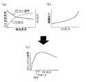
【0037】
図4は燃料電池20としての効率を説明するための説明図であり、図4(a)は電流密度と単セル単体の効率、電池(FC)出力との関係を表す説明図、図4(b)は補機動力とFC出力との関係を表す説明図、図4(c)はFC出力とFCシステム効率との関係を表す説明図である。単セルでは、発電のための燃料ガス(酸素、改質ガス)は、電流密度を高めて発電量を増やそうとする際、それに応じて増量供給される。このようにガス供給が増えると、既述した陰陽での電極反応に供することなく単セルを通過するガス量も増え、発電に未関与のガス量が増えることになる。よって、単セル効率を供給ガス量当たりの発電量(電流密度)と規定すると、図4(a)に示すように、電流密度が増えると単セル効率は低下する。なお、単セルの集合である燃料電池20としては、その出力(FC出力)は、図中点線で示すように、電流密度が大きくなるほど大きくなる。
【0038】
一方、上記したエアコンプレッサ66等の周辺装置は、供給ガス量の増加(即ち、FC出力)に応じてほぼ増加する動力を必要とし、FC出力が低い場合であっても所定の動力を必要とする(図4(b)参照)。これらの結果、燃料電池20としてのシステム効率(例えば、発電量から補機駆動に要する電力を差し引いた電力をガス供給量で除算した値)は、図4(c)に示すように、FC出力が小さいほど低下する。
【0039】
DC/DCコンバータ36は、燃料電池20および2次電池30が出力する電気エネルギの電圧を変換して補機類34に供給する。モータ32を駆動するのに必要な電圧は、通常200V〜300V程度であり、燃料電池20および2次電池30からはこれに見合った電圧が出力されている。しかしながら、既述したウオータポンプなどの補機類34を駆動するときの電圧は12V程度であり、燃料電池20および2次電池30から出力される電圧をそのままの状態で供給することはできない。したがって、DC/DCコンバータ36によって電圧を降下させている。
【0040】
上記した燃料電池側のスイッチ20aや2次電池側のスイッチ30aを切り替えることによって、燃料電池20および2次電池30とモータ32とを接続したり切り離したりすることができる。上記各スイッチの接続状態は、制御部50によって制御されている。
【0041】
残存容量モニタ46は、2次電池30の残存容量を検出するものであり、ここではSOCメータによって構成されている。SOCメータは2次電池30における充電・放電の電流値と時間とを積算するものであり、この値を基に制御部50は2次電池30の残存容量を演算する。ここで残存容量モニタ46は、SOCメータの代わりに電圧センサによって構成することとしてもよい。2次電池30は、その残存容量が少なくなるにつれて電圧値が低下するため、この性質を利用して電圧を測定することによって2次電池30の残存容量を検出することができる。このような電圧センサは制御部50に接続させるものであり、制御部50に予め電圧センサにおける電圧値と残存容量との関係を記憶しておくことによって、電圧センサから入力される測定値を基に制御部50は2次電池30の残存容量を求めることができる。あるいは、残存容量モニタ46は、2次電池30の電解液の比重を測定して残存容量を検出する構成としてもよい。
【0042】
制御部50は、マイクロコンピュータを中心とした論理回路として構成され、CPU52、ROM54、RAM56および入出力ポート58からなる。CPU52は、予め設定された制御プログラムに従って所定の演算などを実行する。ROM54には、CPU52で各種演算処理を実行するのに必要な制御プログラムや制御データなどが予め格納されており、RAM56には、同じくCPU52で各種演算処理を実行するのに必要な各種データが一時的に読み書きされる。入出力ポート58は、残存容量モニタ46など各種センサからの検出信号などを入力すると共に、CPU52での演算結果に応じて、インバータ80などに駆動信号を出力して燃料電池システムの各部の駆動状態を制御する。
【0043】
図1では、制御部50に関しては、残存容量モニタ46からの検出信号および電流センサ90からの信号の入力と、インバータ80の駆動信号の出力と、制御装置33との間の信号のやり取りのみを示したが、制御部50はこの他にも燃料電池システムにおける種々の制御を行なっている。制御部50による図示しない制御の中で主要なものとしては、燃料電池20の運転状態の制御を挙げることができる。既述したように、エアコンプレッサ66やマスフロコントローラに駆動信号を出力して酸化ガス量や燃料ガス量を制御したり、改質器64に供給するメタノールおよび水の量を制御したり、燃料電池20の温度管理や改質器64の温度管理も制御部50が行なっている。
【0044】
インバータ80は、燃料電池20や2次電池30から供給される直流電流を、3相交流電流に変換してモータ32に供給する。ここでは、制御部50からの指示に基づいて、モータ32に供給する3相交流の振幅(実際にはパルス幅)および周波数を調節することによって、モータ32で発生する駆動力を制御可能となっている。このインバータ80は、6個のスイッチング素子(例えば、バイポーラ形MOSFET(IGBT))を主回路素子として構成されており、これらのスイッチング素子のスイッチング動作により燃料電池20および2次電池30から供給される直流電流を任意の振幅および周波数の三相交流に変換する。インバータ80が備える各スイッチング素子は、導電ラインにより制御部50に接続されており、制御部50からの駆動信号によりそのスイッチングのタイミングの制御を受ける。
【0045】
このインバータ80と燃料電池20或いは2次電池30との接続状態は上記のスイッチ20a、30aの制御により決定される。つまり、インバータ80と燃料電池20との接続のほか、インバータ80と2次電池30の接続や、インバータ80への燃料電池20と2次電池30の同時接続が可能である。そして、これらの接続状態を採る間において、燃料電池20の出力制御(発電運転制御)を任意に実行でき、また、2次電池30の出力制御(出力ON・出力OFFの制御)も任意に実行できる。これに対し、既述した特開平7−240212号ではその構成から燃料電池や2次電池を任意に出力調整できないので、本実施例では、この特開平7−240212号のシステムに対して有利である。
【0046】
電流センサ90は、2次電池30からの出力電流を検出する。2次電池30の出力状態は放電の場合も充電の場合もあるが、以後、充放電両方の場合について出力電流という。この電流センサ90は制御部50と接続しており、電流センサ90によって検出された電流値は制御部50に入力される。入力された電流値は、2次電池30における充放電状態を判断する際に用いられる。
【0047】
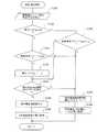
次に、上記した構成を有する燃料電池システム10が実行する燃料電池制御について説明する。図5はこの燃料電池制御の処理の内容を表すフローチャートである。この燃料電池制御は、燃料電池システム10を搭載する車両において、この燃料電池システムを始動させる所定のスタートスイッチがオン状態になったときから、CPU52によって所定時間ごと、例えば10μsecごとに実行される。
【0048】
本ルーチンが実行されると、まず、本システムを搭載した電気自動車の運転者がアクセル操作を介して要求する駆動要求パワーの読み込みと、2次電池30の残存容量Qの読み込みを実行する(ステップS100)。この駆動要求パワーは、車両を運転者の要求に応じてモータ32を回転させるためのパワー(電力)であり、燃料電池20の発電電力と2次電池30の放電電力で賄われる。この場合、駆動要求パワーは、アクセルペダル33aの操作量(アクセルペダルポジションセンサ33bの出力)を制御装置33を経て入力することで読み込み演算される。また、2次電池30の残存容量Qは残存容量モニタ46の出力値から読み込み演算される。これら読み込み演算に続いては、燃料電池20を間欠的に運転する間欠運転モードである旨を示す間欠フラグfkのセット状態を判定する(ステップS110)。この間欠フラグfkは、後述の処理にてセット・リセットされ、セット状態であれば燃料電池20を間欠運転させることを、リセット状態であれば燃料電池20を連続運転させることを表す。
【0049】
ここで、間欠フラグfk=0(リセット状態;連続運転)であると判定した場合は、駆動要求パワーが所定の閾値パワーXpwより小さいか否かの判定を行う(ステップS120)。閾値パワーXpwは、図4(c)に示すように、燃料電池20の出力が低いためにシステム効率が低くなっている領域の値(燃料電池出力)であり、本実施例では、燃料電池20の発電能力(電力供給能力)の約10%に設定されている。なお、この閾値パワーXpwは、2次電池30の充放電能力やステップS100で読み込んだ残存容量Q等に応じて種々設定することが可能であり、上記したものに限られるわけではない。
【0050】
このステップS120で肯定判定した場合は、ステップS110での判定(fk=0)を受けて燃料電池20を連続運転させる状況ではあるものの、駆動要求パワーが閾値パワーXpwより小さいことになる。よって、この場合は、燃料電池20の運転モードを連続運転モードから間欠運転モードに移行する旨を示すよう、間欠フラグfkに値1を入れてこれをセットする(ステップS130)。次に、ステップS100で読み取った残存容量Qと駆動要求パワーとを対比し、2次電池30の残存容量Qだけの電力でモータ32を駆動要求パワー通りに回転させることができるか否かを判定する(ステップS140)。つまり、残存容量Qで駆動要求パワーを充足できるかを判定する。
【0051】
このステップS140で、残存容量Qで駆動要求パワーを充足できると判定した場合は、低い発電領域での燃料電池20と上記したエアコンプレッサ66等の燃料電池周辺装置を含む燃料電池機器群の運転を実際に停止する(ステップS150)。続いて、2次電池30から残存容量Qの電力をモータ32に供給して(ステップS160)、一旦本ルーチンを終了する。これにより、モータ32は2次電池30のみからの電力供給により回転し、車両は駆動要求パワーで駆動する。
【0052】
一方、ステップS140で、残存容量Qだけでは駆動要求パワーを充足できないと判定した場合は、2次電池30と燃料電池20を併用すべく、上記の燃料電池機器群を発電運転させると共に、燃料電池20の連続運転モードに移行する旨を示すよう、間欠フラグfkに値0「ゼロ」を入れてこれをリセットする(ステップS170)。これにより、2次電池30の残存容量Qの電力と燃料電池20が発電した電力とで、モータ32の回転並びに駆動要求パワーでの車両駆動が可能となる。
【0053】
このステップS170に続いては、駆動要求パワーが2次電池30の残存容量Qの電力と燃料電池20が発電した電力とで賄えるよう、2次電池30と燃料電池20とからモータ32に電力を供給して(ステップS180)、一旦本ルーチンを終了する。より詳しく説明すると、駆動要求パワーと残存容量QはステップS100での読み込みにより既知であることから、この両者から、燃料電池20で発電すべき電力は定まる。よって、この定まった電力を発電するための既述した燃料ガス供給量を演算し、その結果に応じて上記の周辺装置を運転し、上記定まった電力を燃料電池20で発電する。これにより、モータ32は2次電池30と燃料電池20とからの電力供給により回転し、車両は駆動要求パワーで駆動する。
【0054】
また、ステップS120で駆動要求パワーが閾値パワーXpw以上であると判定した場合は、駆動要求パワーを得るには燃料電池20をシステム効率が高い状況で発電運転をすればよいと言える。よって、駆動要求パワーを2次電池30の電力と燃料電池20の発電電力で賄うべくステップS170に移行する。これにより、モータ32は2次電池30と燃料電池20とからの電力供給により回転し、車両は駆動要求パワーで駆動する。
【0055】
一方、既述したステップS110で、間欠フラグfk=1(セット状態;間欠運転)であると判定した場合は、駆動要求パワーが閾値パワーXpw+αより大きいか否かの判定を行う(ステップS190)。ここで、肯定判定した場合は、ステップS110での判定(fk=1)を受けて燃料電池20を間欠運転させる状況ではあるものの、駆動要求パワーが閾値パワーXpw+αより大きいことになる。よって、この大きな駆動要求パワーを2次電池30の電力と燃料電池20の発電電力で賄うべく、ステップS170に移行する。これにより、モータ32は2次電池30と燃料電池20とからの電力供給により回転し、車両は駆動要求パワーで駆動する。
【0056】
また、ステップS190で否定判定した場合は、駆動要求パワーはまだ小さいままである。よって、燃料電池20とその周辺装置を含む燃料電池機器群を停止したままこの駆動要求パワーを2次電池30の残存容量Qで賄うべく、ステップS140に移行して、既述したそれ以降の処理を実行する。これにより、燃料電池システム10は、燃料電池機器群の停止状況下で(ステップS150)、2次電池30の残存容量Qによりモータ32を回転させて(ステップS160)、車両を駆動要求パワーで駆動する。また、残存容量Qでは不足の場合は(ステップS140;否定判定)、2次電池30と燃料電池20とからの電力供給によりモータ32を回転させて(ステップS170、180)、車両を駆動要求パワーで駆動する。
【0057】
以上説明したように本実施例の燃料電池システム10は、アクセルペダル33aの踏込操作を介して運転者が要求する車両の駆動要求パワーの大きさにより、燃料電池20とその周辺装置を含む燃料電池機器群の運転・停止を定める。即ち、この駆動要求パワーが燃料電池20にとって高負荷領域の発電運転で得られるものである場合には(ステップS120;否定判定)、燃料電池機器群を運転して燃料電池20で発電を起こし(ステップS170)、この電力と2次電池30の電力でモータ32を回転させて車両を駆動する(ステップS180)。よって、この場合は、燃料電池20を高負荷領域で効率よく発電運転でき、燃料電池システム10、延いてはこれを搭載した電気自動車としてシステム効率を向上することができる。
【0058】
一方、駆動要求パワーが燃料電池20にとって低負荷領域の発電運転で得られるものである場合には(ステップS120;肯定判定)、2次電池30の残存容量Qでモータ回転を賄うことができれば(ステップS140;肯定判定)、燃料電池20とその周辺装置を含む燃料電池機器群を停止させ(ステップS150)、2次電池30単独でその残存容量Qによりモータ32を回転させて(ステップS160)、車両を駆動要求パワーで駆動する。よって、燃料電池20を低負荷領域で発電運転しないようにできるので、燃料電池20の無駄な発電を起こすことが無くなり燃料電池システム10、延いてはこれを搭載した電気自動車としてシステム効率を向上することができる。しかも、燃料電池20の運転停止と併せてエアコンプレッサ66等の周辺装置の運転も停止するので、これら装置の運転に要するエネルギも使わないようにしてシステム効率をより向上することができる。
【0059】
また、駆動要求パワーが低負荷領域のものであっても、2次電池30の残存容量Qがモータ回転に不足する場合は(ステップS140;否定判定)、燃料電池機器群を運転させて、2次電池30と燃料電池20との電力でモータ32を回転させて(ステップS170、180)、車両を駆動要求パワーで駆動する。このため、運転者が意図する駆動状態で車両を駆動できるので、運転者に違和感を与えない。
【0060】
また、本実施例では、駆動要求パワーが閾値パワーXpw以下であるために燃料電池20を停止させた状況から、駆動要求パワーが増加したために燃料電池20の運転を行う際には、この駆動要求パワーが閾値パワーXpw+αより大きくなるまで燃料電池20を停止させたままとした(ステップS190)。よって、駆動要求パワーが閾値パワーXpwの周辺で増減しても、燃料電池20の運転・停止を繰り返すようなハンチングを回避できる。このため、ハンチングによる不具合、例えば、燃料電池20の周辺装置であるポンプ等の異音発生等を回避できる。
【0061】
以上本発明の実施例について説明したが、本発明は上記の実施例や実施形態になんら限定されるものではなく、本発明の要旨を逸脱しない範囲において種々なる態様で実施し得ることは勿論である。
【0062】
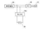
例えば、燃料電池20の出力制御(発電運転制御)と2次電池30の出力制御を任意に実行できるようにするに当たり、次のようにすることもできる。図6は変形例の要部の構成を説明するためのブロック図である。この図6に示す変形例では、DC/DCコンバータ30bを介在させて、2次電池30を燃料電池20に並列に接続した。こうすれば、DC/DCコンバータ30bにより2次電池30の出力調整をした上で、当該出力(電力)をモータ32に供給できる。
【0063】
また、上記実施例では、燃料電池20と補機類34を含む燃料電池スタックが一つである場合について説明したが、複数の燃料電池スタックを有するシステムについても適用できる。この場合は、各燃料電池スタックごとに、負荷の大きさに基づいて、燃料電池発電停止や補記類までを含めた運転停止を実行するようにすることができ、こうすれば、各燃料電池スタックでの発電を無駄にすることがない。
【図面の簡単な説明】
【図1】本発明の好適な一実施例である燃料電池システム10を搭載した電気自動車の概略構成を表すブロック図である。
【図2】燃料電池20を構成する単セル28の構成を表す断面模式図である。
【図3】燃料電池20とその周辺装置とからなる燃料電池部60の構成を表すブロック図である。
【図4】燃料電池20としての効率を説明するための説明図である。
【図5】燃料電池20を運転制御する燃料電池制御の処理の内容を表すフローチャートである。
【図6】変形例の要部の構成を説明するためのブロック図である。
【符号の説明】
10…燃料電池システム
20…燃料電池
21…電解質膜
22…アノード
23…カソード
24,25…セパレータ
24P…燃料ガス流路
25P…酸化ガス流路
26,27…集電板
28…単セル
30…2次電池
32…モータ
33…制御装置
33a…アクセルペダル
33b…アクセルペダルポジションセンサ
34…補機類
36…DC/DCコンバータ
46…残存容量モニタ
50…制御部
60…燃料電池部
61a,62a…ポンプ
61…メタノールタンク
62…水タンク
64…改質器
66…エアコンプレッサ
67…電磁バルブ
68…燃料供給路
69…空気供給路
70…分岐空気路
71…燃料排出路
80…インバータ
90…電流センサ[0001]
BACKGROUND OF THE INVENTION
The present invention relates to a fuel cell system and an electric vehicle, and more particularly to a fuel cell system including a fuel cell and a secondary battery, and an electric vehicle equipped with the fuel cell system.
[0002]
[Prior art]
Conventionally, as this type of fuel cell system, there has been proposed a fuel cell system including a fuel cell and a secondary battery as power sources and supplying electric power from both the batteries to a load such as a motor (for example, Japanese Patent Laid-Open No. 7-240212). Such). This fuel cell system does not simply control the output of the fuel cell according to the increase or decrease of the load, but operates the fuel cell in a range where the conversion efficiency of the fuel used is high, thereby improving the conversion efficiency of the system. I try to keep it in a high range.
[0003]
[Problems to be solved by the invention]
In the above-described conventional fuel cell system, the fuel cell is operated with high conversion efficiency regardless of the amount of power required to be supplied to the load. Therefore, even when the load is small, the fuel cell continues to operate in the high conversion efficiency range, and the power generation of the fuel cell may be wasted.
[0004]
The present invention has been made to solve the above problems, and aims to reduce the waste of power generation in a fuel cell and to improve the efficiency of the entire system including the fuel cell and the secondary battery.
[0005]
[Means for solving the problems and their functions and effects]
In order to solve at least a part of the problem, the fuel cell system of the present invention includes:
A fuel cell and a secondary battery connected in parallel;
A fuel cell system having power supply means for supplying power to the load from both the batteries to the load,
The power supply means
Detection means for detecting the magnitude of the connected load;
Detected during power generation operation of the fuel cell.Stop means for stopping the power generation operation of the fuel cell and stopping power supply from the fuel cell when the output load is in a predetermined low load region;
The gist is to provide
[0006]
In the fuel cell system of the present invention having the above configuration, when the load is in a predetermined low load region, the power generation operation of the fuel cell is stopped and the power supply from the fuel cell is stopped. In this case, power is supplied from the secondary battery to the load by the power control means. For this reason, since the power generation operation of the fuel cell is not required in the low load region, the power generation of the fuel cell is not wasted and the efficiency of the entire system can be improved.
The low load region can be a region of about 10% or less of the power supply capacity of the fuel cell.
[0007]
In addition to the first load when the generated power obtained by the fuel cell is supplied to the outside of the fuel cell system, the above-described load includes not only the first load but also the second load involved in maintaining the fuel cell system (that is, the fuel). Load in the battery system). And if the magnitude | size of 2nd load is the said low load area | region, a system maintenance will be aimed at by the electric power supply from a secondary battery.
[0008]
In this case, as in the case of the size of the connected load, if the system efficiency of the fuel cell system is below a predetermined value, the power generation operation of the fuel cell is stopped and the power supply from the fuel cell is stopped. You can also Even in this case, when the system efficiency is low, power can be supplied from the secondary battery so that the power generation of the fuel cell is not wasted.
[0009]
The fuel cell system of the present invention having the above configuration can also take the following aspects. In other words, the stopping means may include means for stopping the operation of the fuel cell auxiliary machine involved in the power generation operation.
In this way, the energy required to operate these fuel cell auxiliary machines can be prevented from being used, and the system efficiency can be further improved.
[0010]
The power supply means may be
A hand for detecting the remaining capacity of the secondary batteryWith steps,
When the detected remaining capacity can cover the detected load in the low load region, the operation of the stopping meansRunCan be.
[0012]
The electric vehicle of the present invention is
An electric vehicle that obtains driving force by rotating a motor with electric energy and transmitting the rotational force of the motor to an axle,
A fuel cell system having a fuel cell and a secondary battery connected in parallel, and a power supply means for supplying power to the load from the two batteries to the load;
The power supply means of the fuel cell system includes:
Detection means for detecting the magnitude of the connected load;
Detected during power generation operation of the fuel cell.When the output load is a predetermined low load region, the power supply operation of the fuel cell is stopped to stop the power supply from the fuel cell,
The motor is supplied with electric power from the fuel cell system.
This is the gist.
[0013]
In the electric vehicle of the present invention having the above configuration, when the rotational force of the motor required for driving the vehicle is in a predetermined region (low load region), the motor is operated from the secondary battery without generating the fuel cell. Supply power to For this reason, in the low load region, since the power generation operation of the fuel cell is not required, the power generation of the fuel cell is not wasted and the system efficiency can be improved as an electric vehicle.
[0014]
In this electric vehicle, if the operation of the fuel cell auxiliary machine is stopped in accordance with the power generation operation of the fuel cell, the energy required for the operation of the fuel cell auxiliary machine can be prevented from being used. Efficiency can be improved.
[0015]
Further, when the load is low and the detected load at that time (required motor rotational force) cannot be covered by the remaining capacity of the secondary battery, the power generation operation of the fuel cell can be performed. By doing so, the electric power obtained by the power generation operation of the fuel cell is supplied to the motor and rotated, so that a situation such as motor stoppage does not occur and vehicle behavior due to motor stoppage does not occur. Therefore, it is possible to prevent the driver who performs the operation for driving the vehicle by rotating the motor from being given an uncomfortable feeling due to the vehicle behavior due to the motor stop.
[0016]
Further, as in the case where the connected load is in the low load region, when the system efficiency of the fuel cell system is below a predetermined value, the power generation operation of the fuel cell is stopped and the power supply from the fuel cell is stopped. You can also Even in this case, when the vehicle travels when the system efficiency is low, it is possible to travel by supplying power from the secondary battery so that the power generation of the fuel cell is not wasted.
[0017]
DETAILED DESCRIPTION OF THE INVENTION
In order to further clarify the configuration and operation of the present invention described above, embodiments of the present invention will be described based on examples. FIG. 1 is a block diagram showing an outline of the configuration of an electric vehicle equipped with a
[0018]
The
[0019]
H2 → 2H++ 2e- ... (1)
(1/2) O2+ 2H++ 2e- → H2O ... (2)
H2 + (1/2) O2 → H2O ... (3)
[0020]
Equation (1) represents the reaction on the cathode side, Equation (2) represents the reaction on the anode side, and Equation (3) represents the reaction occurring in the entire battery. FIG. 2 is a cross-sectional view illustrating the configuration of the
[0021]
The
[0022]
Here, the
[0023]
Both the
[0024]
The
[0025]
The configuration of the
[0026]
Although not shown in the block diagram of FIG. 1, in order to actually generate power using a fuel cell, a predetermined peripheral device (fuel cell auxiliary device) is required in addition to the fuel cell body having the stack structure. . FIG. 3 is a block diagram illustrating the configuration of the
[0027]
The
[0028]
CHThreeOH → CO + 2H2 ... (4)
CO + H2O → CO2+ H2 ... (5)
CHThreeOH + H2O → CO2+ 3H2 (6)
[0029]
In the reforming reaction of methanol performed in the
[0030]
The
[0031]
The fuel exhaust gas after being used for the cell reaction at the
[0032]
Such a
[0033]
The
[0034]
Returning to FIG. 1, the configuration of each unit will be further described.
The
[0035]
The
[0036]
The
[0037]
FIG. 4 is an explanatory diagram for explaining the efficiency of the
[0038]
On the other hand, peripheral devices such as the above-described
[0039]
The DC /
[0040]
By switching the
[0041]
The remaining capacity monitor 46 detects the remaining capacity of the
[0042]
The
[0043]
In FIG. 1, with respect to the
[0044]
The
[0045]
The connection state between the
[0046]
The
[0047]
Next, fuel cell control executed by the
[0048]
When this routine is executed, first, reading of the drive request power requested by the driver of the electric vehicle equipped with this system through the accelerator operation and reading of the remaining capacity Q of the
[0049]
Here, when it is determined that the intermittent flag fk = 0 (reset state; continuous operation), it is determined whether or not the drive request power is smaller than a predetermined threshold power Xpw (step S120). As shown in FIG. 4C, the threshold power Xpw is a value (fuel cell output) in a region where the system efficiency is low because the output of the
[0050]
If an affirmative determination is made in step S120, the drive request power is smaller than the threshold power Xpw although the
[0051]
When it is determined in this step S140 that the required drive power can be satisfied with the remaining capacity Q, the operation of the fuel cell device group including the
[0052]
On the other hand, step S140When it is determined that the required drive power cannot be satisfied with the remaining capacity Q alone, the fuel cell device group is operated to generate power and the
[0053]
Subsequent to step S170, power is supplied from the
[0054]
If it is determined in step S120 that the required drive power is equal to or higher than the threshold power Xpw, it can be said that the
[0055]
On the other hand, if it is determined in step S110 described above that the intermittent flag fk = 1 (set state; intermittent operation), it is determined whether or not the drive request power is greater than the threshold power Xpw + α (step S190). Here, when the determination is affirmative, although the
[0056]
Further, when a negative determination is made in step S190, the drive request power is still small. Therefore, in order to cover the required power for driving with the remaining capacity Q of the
[0057]
As described above, the
[0058]
On the other hand, if the required drive power is obtained by the power generation operation in the low load region for the fuel cell 20 (step S120; affirmative determination), if the remaining capacity Q of the
[0059]
Even if the required drive power is in the low load region, if the remaining capacity Q of the
[0060]
Further, in this embodiment, when the
[0061]
Although the embodiments of the present invention have been described above, the present invention is not limited to the above-described embodiments and embodiments, and can of course be implemented in various modes without departing from the gist of the present invention. is there.
[0062]
For example, in order to be able to arbitrarily execute the output control (power generation operation control) of the
[0063]
Moreover, although the said Example demonstrated the case where there was one fuel cell stack containing the
[Brief description of the drawings]
FIG. 1 is a block diagram showing a schematic configuration of an electric vehicle equipped with a
2 is a schematic cross-sectional view showing a configuration of a
FIG. 3 is a block diagram showing a configuration of a
FIG. 4 is an explanatory diagram for explaining the efficiency of the
FIG. 5 is a flowchart showing the contents of a fuel cell control process for controlling the operation of the
FIG. 6 is a block diagram for explaining a configuration of a main part of a modified example.
[Explanation of symbols]
10. Fuel cell system
20 ... Fuel cell
21 ... electrolyte membrane
22 ... Anode
23 ... Cathode
24, 25 ... separator
24P ... Fuel gas flow path
25P ... Oxidizing gas flow path
26, 27 ... current collector
28 ... Single cell
30 ... Secondary battery
32 ... Motor
33 ... Control device
33a ... Accelerator pedal
33b ... accelerator pedal position sensor
34 ... Auxiliary machinery
36 ... DC / DC converter
46 ... Remaining capacity monitor
50. Control unit
60 ... Fuel cell section
61a, 62a ... pump
61 ... Methanol tank
62 ... Water tank
64 ... reformer
66 ... Air compressor
67 ... Electromagnetic valve
68 ... Fuel supply passage
69 ... Air supply path
70: Branch air passage
71 ... Fuel discharge path
80 ... Inverter
90 ... Current sensor
Claims (12)
Translated fromJapanese負荷に対して前記両電池から前記負荷への電力の供給を行なう電力供給手段とを有する燃料電池システムであって、
前記電力供給手段は、
接続される負荷の大きさを検出する検出手段と、
前記燃料電池の発電運転中に検出負荷が所定の低負荷領域である場合には、前記燃料電池の発電運転を停止して前記燃料電池からの電力供給を停止する停止手段と
を備えた燃料電池システム。A fuel cell and a secondary battery connected in parallel;
A fuel cell system having power supply means for supplying power from both the batteries to the load with respect to a load,
The power supply means
Detection means for detecting the magnitude of the connected load;
Fueldetection loadduring power generation operation of the fuel cell when a predetermined low load region, that includes a stopping means for stopping the power supply from the fuel cell to stop power generation operation of the fuel cell Battery system.
前記停止手段は、前記発電運転に関与する燃料電池補機の運転を停止する手段を有する、燃料電池システム。The fuel cell system according to claim 1, wherein
The fuel cell system, wherein the stopping means includes means for stopping the operation of a fuel cell auxiliary machine involved in the power generation operation.
前記電力供給手段は、
前記2次電池の残存容量を検出する手段を備え、
前記検出残存容量で前記低負荷領域の場合の前記検出負荷を賄えるときには、前記停止手段の動作を実行する、燃料電池システム。The fuel cell system according to claim 1 or 2,
The power supply means
Comprising a means to detect the remaining capacity of the secondarybattery,
When it can cover the load detected in the case of the low load region by the detecting remaining capacity,that perform operation of the stop means, the fuel cell system.
前記低負荷領域は、前記燃料電池の電力供給能力の約10%以下の領域とされている、燃料電池システム。A fuel cell system according to any one of claims 1 to 3,
The fuel cell system, wherein the low load region is a region of about 10% or less of the power supply capacity of the fuel cell.
前記接続される負荷は、燃料電池システム外への電力供給先である第1の負荷と、燃料電池システム内への電力供給先である第2の負荷とからなる、燃料電池システム。The fuel cell system according to claim 1, wherein
The connected load includes a first load that is a power supply destination to the outside of the fuel cell system and a second load that is a power supply destination to the inside of the fuel cell system.
負荷に対して前記両電池から前記負荷への電力の供給を行なう電力供給手段とを有する燃料電池システムであって、
前記電力供給手段は、
燃料電池システムのシステム効率が所定値以下である場合には、前記燃料電池の発電運転を停止して前記燃料電池からの電力供給を停止する停止手段を備えた燃料電池システム。A fuel cell and a secondary battery connected in parallel;
A fuel cell system having power supply means for supplying power from both the batteries to the load with respect to a load,
The power supply means
A fuel cell system comprising stop means for stopping power generation operation of the fuel cell and stopping power supply from the fuel cell when the system efficiency of the fuel cell system is equal to or less than a predetermined value.
並列に接続された燃料電池と2次電池と、負荷に対して前記両電池から前記負荷への電力の供給を行なう電力供給手段とを有する燃料電池システムを搭載し、
前記燃料電池システムの前記電力供給手段は、
接続される負荷の大きさを検出する検出手段と、
前記燃料電池の発電運転中に検出負荷が所定の低負荷領域である場合には、前記燃料電池の発電運転を停止して前記燃料電池からの電力供給を停止する停止手段とを備え、
前記モータは、前記燃料電池システムから電力の供給を受ける、電気自動車。An electric vehicle that obtains driving force by rotating a motor with electric energy and transmitting the rotational force of the motor to an axle,
A fuel cell system having a fuel cell and a secondary battery connected in parallel, and a power supply means for supplying power to the load from the two batteries to the load;
The power supply means of the fuel cell system includes:
Detection means for detecting the magnitude of the connected load;
Whendetection loadduring power generation operation of the fuel cell is a predetermined low-load region, and a stop means for stopping the power supply from the fuel cell to stop power generation operation of the fuel cell,
The motor is an electric vehicle that is supplied with electric power from the fuel cell system.
前記接続される負荷は、燃料電池システム外への電力供給先である第1の負荷と、燃料電池システム内への電力供給先である第2の負荷とからなる、電気自動車。The electric vehicle according to claim 7,
The connected load is an electric vehicle including a first load that is a power supply destination to the outside of the fuel cell system and a second load that is a power supply destination to the inside of the fuel cell system.
並列に接続された燃料電池と2次電池と、負荷に対して前記両電池から前記負荷への電力の供給を行なう電力供給手段とを有する燃料電池システムを搭載し、
前記燃料電池システムの前記電力供給手段は、
燃料電池システムのシステム効率が所定値以下である場合には、前記燃料電池の発電運転を停止して前記燃料電池からの電力供給を停止する停止手段を備え、
前記モータは、前記燃料電池システムから電力の供給を受ける、電気自動車。An electric vehicle that obtains driving force by rotating a motor with electric energy and transmitting the rotational force of the motor to an axle,
A fuel cell system having a fuel cell and a secondary battery connected in parallel, and a power supply means for supplying power to the load from the two batteries to the load;
The power supply means of the fuel cell system includes:
When the system efficiency of the fuel cell system is equal to or lower than a predetermined value, the fuel cell system includes stop means for stopping the power generation operation of the fuel cell and stopping the power supply from the fuel cell,
The motor is an electric vehicle that is supplied with electric power from the fuel cell system.
前記両電池から前記負荷への電力の供給を行なう電力供給手段とを有する燃料電池システムであって、
前記電力供給手段は、
接続される前記負荷の大きさを検出する検出手段と、
前記燃料電池の発電運転中に検出負荷が所定の低負荷領域である場合には、前記燃料電池へのガス供給を停止して前記燃料電池からの電力供給を停止する停止手段と
を備えた燃料電池システム。A fuel cell and a secondary battery connected in parallel to the load;
A fuel cell system having power supply means for supplying power from both the batteries to the load,
The power supply means
Detecting means for detecting the magnitude of the load connected;
Whendetection loadduring power generation operation of the fuel cell is a predetermined low-load region, and a stop means for stopping the power supply from the fuel cell to stop gas supply to the fuel cell Fuel cell system.
前記停止手段は、前記燃料電池のカソードへのガス供給を停止する、燃料電池システム。The fuel cell system according to claim 10, wherein
The fuel cell system, wherein the stop means stops gas supply to the cathode of the fuel cell.
前記両電池から前記モータへの電力供給を行なう電力供給手段とを有する燃料電池システムであって、
前記電力供給手段は、
前記モータに求められる負荷の大きさを検出する検出手段と、
前記燃料電池の発電運転中に検出負荷が所定の低負荷領域である場合には、前記2次電池のみから前記モータに電力を供給する手段と
を備えた燃料電池システム。A fuel cell and a secondary battery connected in parallel to a motor that rotates by receiving power and transmits the rotational force to the axle;
A fuel cell system having power supply means for supplying power from both the batteries to the motor,
The power supply means
Detecting means for detecting the magnitude of the load required for the motor;
A fuel cell system including awherein whendetection loadduring the power generation operation of the fuel cell is a predetermined low-load region, means for supplying electric power to the motor only the secondary battery.
Priority Applications (1)
| Application Number | Priority Date | Filing Date | Title |
|---|---|---|---|
| JP2000120830AJP4654484B2 (en) | 2000-04-21 | 2000-04-21 | Fuel cell system and electric vehicle |
Applications Claiming Priority (1)
| Application Number | Priority Date | Filing Date | Title |
|---|---|---|---|
| JP2000120830AJP4654484B2 (en) | 2000-04-21 | 2000-04-21 | Fuel cell system and electric vehicle |
Publications (3)
| Publication Number | Publication Date |
|---|---|
| JP2001307758A JP2001307758A (en) | 2001-11-02 |
| JP2001307758A5 JP2001307758A5 (en) | 2007-06-07 |
| JP4654484B2true JP4654484B2 (en) | 2011-03-23 |
Family
ID=18631581
Family Applications (1)
| Application Number | Title | Priority Date | Filing Date |
|---|---|---|---|
| JP2000120830AExpired - Fee RelatedJP4654484B2 (en) | 2000-04-21 | 2000-04-21 | Fuel cell system and electric vehicle |
Country Status (1)
| Country | Link |
|---|---|
| JP (1) | JP4654484B2 (en) |
Families Citing this family (24)
| Publication number | Priority date | Publication date | Assignee | Title |
|---|---|---|---|---|
| JP3719229B2 (en) | 2001-12-19 | 2005-11-24 | トヨタ自動車株式会社 | Power supply |
| JP3911435B2 (en) | 2002-04-11 | 2007-05-09 | トヨタ自動車株式会社 | Power supply system and control method thereof |
| JP4185708B2 (en)* | 2002-06-04 | 2008-11-26 | トヨタ自動車株式会社 | Power supply |
| ES2320924T3 (en) | 2002-06-10 | 2009-05-29 | Toyota Jidosha Kabushiki Kaisha | FUEL BATTERY VEHICLE. |
| JP4725534B2 (en)* | 2002-06-10 | 2011-07-13 | トヨタ自動車株式会社 | Vehicle with fuel cell |
| JP2004056868A (en) | 2002-07-17 | 2004-02-19 | Honda Motor Co Ltd | Idle control device for fuel cell vehicle |
| JP3879635B2 (en) | 2002-09-06 | 2007-02-14 | 日産自動車株式会社 | Mobile fuel cell power plant system |
| JP4904661B2 (en)* | 2002-11-21 | 2012-03-28 | 株式会社デンソー | Fuel cell system |
| JP4182732B2 (en) | 2002-11-22 | 2008-11-19 | トヨタ自動車株式会社 | FUEL CELL SYSTEM, MOBILE BODY MOUNTING THE SAME, AND METHOD FOR CONTROLLING FUEL CELL SYSTEM |
| JP4034194B2 (en)* | 2003-01-17 | 2008-01-16 | 株式会社日本総合研究所 | Power supply system and housing complex |
| JP4525008B2 (en) | 2003-07-02 | 2010-08-18 | トヨタ自動車株式会社 | Energy output device and method for controlling energy output device |
| US7518262B2 (en) | 2003-07-23 | 2009-04-14 | The Japan Research Insitute, Limited | Power supply system, multiple dwelling, and computer program |
| JP4982938B2 (en)* | 2003-07-31 | 2012-07-25 | 株式会社エクォス・リサーチ | Fuel cell system |
| JP4811626B2 (en) | 2003-08-25 | 2011-11-09 | トヨタ自動車株式会社 | Fuel cell system for vehicle and electric vehicle |
| JP4534122B2 (en)* | 2003-12-26 | 2010-09-01 | トヨタ自動車株式会社 | Hybrid system |
| JP4993240B2 (en) | 2004-03-17 | 2012-08-08 | トヨタ自動車株式会社 | Control device |
| JP5002893B2 (en)* | 2004-12-27 | 2012-08-15 | 株式会社デンソー | Fuel cell current measurement device |
| JP4529948B2 (en)* | 2006-06-07 | 2010-08-25 | 日産自動車株式会社 | Control device for fuel cell system |
| JP2008016256A (en)* | 2006-07-04 | 2008-01-24 | Suzuki Motor Corp | Vehicular control device |
| JP4525837B2 (en)* | 2009-08-31 | 2010-08-18 | トヨタ自動車株式会社 | Energy output device and method for controlling energy output device |
| WO2011070746A1 (en)* | 2009-12-10 | 2011-06-16 | パナソニック株式会社 | Fuel cell system, and electronic device |
| US9403444B2 (en) | 2010-09-15 | 2016-08-02 | Audi Ag | In-service fuel cell performance recovery |
| JP5427832B2 (en) | 2011-05-18 | 2014-02-26 | 本田技研工業株式会社 | Fuel cell vehicle |
| CN108134112A (en)* | 2017-12-25 | 2018-06-08 | 东风农业装备(襄阳)有限公司 | Fuel cell system and its application |
Family Cites Families (8)
| Publication number | Priority date | Publication date | Assignee | Title |
|---|---|---|---|---|
| JPH02168802A (en)* | 1988-12-22 | 1990-06-28 | Toyota Autom Loom Works Ltd | Electric vehicle |
| JPH05182675A (en)* | 1991-07-04 | 1993-07-23 | Shimizu Corp | Fuel cell output control method |
| JP3349742B2 (en)* | 1993-01-28 | 2002-11-25 | マツダ株式会社 | Fuel cell vehicle |
| JP3599773B2 (en)* | 1994-02-24 | 2004-12-08 | 株式会社エクォス・リサーチ | Hybrid power supply |
| JPH11164402A (en)* | 1997-11-28 | 1999-06-18 | Aisin Aw Co Ltd | Controller and controlling method for hybrid vehicle |
| JP2000032606A (en)* | 1998-07-14 | 2000-01-28 | Toyota Motor Corp | Vehicle |
| JP2000110602A (en)* | 1998-09-30 | 2000-04-18 | Mazda Motor Corp | Hybrid automobile |
| JP2001143735A (en)* | 1999-11-12 | 2001-05-25 | Isuzu Motors Ltd | Fuel cell system for vehicles |
- 2000
- 2000-04-21JPJP2000120830Apatent/JP4654484B2/ennot_activeExpired - Fee Related
Also Published As
| Publication number | Publication date |
|---|---|
| JP2001307758A (en) | 2001-11-02 |
Similar Documents
| Publication | Publication Date | Title |
|---|---|---|
| JP4654484B2 (en) | Fuel cell system and electric vehicle | |
| JP4372235B2 (en) | Fuel cell system and electric vehicle | |
| JP4049833B2 (en) | Power supply device and electric vehicle | |
| JP3608017B2 (en) | Power system | |
| JP4811626B2 (en) | Fuel cell system for vehicle and electric vehicle | |
| CN102655239B (en) | Fuel cell system | |
| JP4591721B2 (en) | Fuel cell system | |
| JPH10271706A (en) | Power supply and electric vehicle | |
| US8420268B2 (en) | Fuel cell system | |
| US8236460B2 (en) | Fuel cell system | |
| US8053123B2 (en) | Fuel cell system with a scavenging device and AC impedance measuring unit | |
| JPH09231991A (en) | Fuel cell system | |
| JP2009151997A (en) | Fuel cell system | |
| JP4031555B2 (en) | Gas supply device | |
| JP2021057128A (en) | Fuel cell system, control method for fuel cell system, and program | |
| CN101454934A (en) | Fuel cell system | |
| JP5146639B2 (en) | Fuel cell system | |
| JP5803686B2 (en) | Fuel cell system and vehicle equipped with the same | |
| JP2007250216A (en) | Fuel cell system and operation method thereof | |
| JP5030013B2 (en) | Fuel cell system | |
| JP2007227278A (en) | Fuel cell device | |
| JP2004235009A (en) | Fuel cell system and mobile device | |
| JP2021061104A (en) | System, control method for system, and program | |
| KR101084078B1 (en) | Fuel cell system and its driving method | |
| JP2008171660A (en) | Fuel cell system |
Legal Events
| Date | Code | Title | Description |
|---|---|---|---|
| A621 | Written request for application examination | Free format text:JAPANESE INTERMEDIATE CODE: A621 Effective date:20070406 | |
| A521 | Request for written amendment filed | Free format text:JAPANESE INTERMEDIATE CODE: A523 Effective date:20070413 | |
| A977 | Report on retrieval | Free format text:JAPANESE INTERMEDIATE CODE: A971007 Effective date:20100204 | |
| A131 | Notification of reasons for refusal | Free format text:JAPANESE INTERMEDIATE CODE: A131 Effective date:20100413 | |
| A521 | Request for written amendment filed | Free format text:JAPANESE INTERMEDIATE CODE: A523 Effective date:20100610 | |
| TRDD | Decision of grant or rejection written | ||
| A01 | Written decision to grant a patent or to grant a registration (utility model) | Free format text:JAPANESE INTERMEDIATE CODE: A01 Effective date:20101124 | |
| A01 | Written decision to grant a patent or to grant a registration (utility model) | Free format text:JAPANESE INTERMEDIATE CODE: A01 | |
| A61 | First payment of annual fees (during grant procedure) | Free format text:JAPANESE INTERMEDIATE CODE: A61 Effective date:20101207 | |
| FPAY | Renewal fee payment (event date is renewal date of database) | Free format text:PAYMENT UNTIL: 20140107 Year of fee payment:3 | |
| FPAY | Renewal fee payment (event date is renewal date of database) | Free format text:PAYMENT UNTIL: 20140107 Year of fee payment:3 | |
| LAPS | Cancellation because of no payment of annual fees |