JP4653965B2 - How to manage I/O interface modules - Google Patents
How to manage I/O interface modulesDownload PDFInfo
- Publication number
- JP4653965B2 JP4653965B2JP2004114011AJP2004114011AJP4653965B2JP 4653965 B2JP4653965 B2JP 4653965B2JP 2004114011 AJP2004114011 AJP 2004114011AJP 2004114011 AJP2004114011 AJP 2004114011AJP 4653965 B2JP4653965 B2JP 4653965B2
- Authority
- JP
- Japan
- Prior art keywords
- input
- output interface
- interface module
- management server
- output
- Prior art date
- Legal status (The legal status is an assumption and is not a legal conclusion. Google has not performed a legal analysis and makes no representation as to the accuracy of the status listed.)
- Expired - Fee Related
Links
Images


Classifications
- G—PHYSICS
- G06—COMPUTING OR CALCULATING; COUNTING
- G06F—ELECTRIC DIGITAL DATA PROCESSING
- G06F3/00—Input arrangements for transferring data to be processed into a form capable of being handled by the computer; Output arrangements for transferring data from processing unit to output unit, e.g. interface arrangements
- G06F3/06—Digital input from, or digital output to, record carriers, e.g. RAID, emulated record carriers or networked record carriers
- G06F3/0601—Interfaces specially adapted for storage systems
- G06F3/0628—Interfaces specially adapted for storage systems making use of a particular technique
- G06F3/0629—Configuration or reconfiguration of storage systems
- G06F3/0635—Configuration or reconfiguration of storage systems by changing the path, e.g. traffic rerouting, path reconfiguration
- G—PHYSICS
- G06—COMPUTING OR CALCULATING; COUNTING
- G06F—ELECTRIC DIGITAL DATA PROCESSING
- G06F3/00—Input arrangements for transferring data to be processed into a form capable of being handled by the computer; Output arrangements for transferring data from processing unit to output unit, e.g. interface arrangements
- G06F3/06—Digital input from, or digital output to, record carriers, e.g. RAID, emulated record carriers or networked record carriers
- G06F3/0601—Interfaces specially adapted for storage systems
- G06F3/0602—Interfaces specially adapted for storage systems specifically adapted to achieve a particular effect
- G06F3/0604—Improving or facilitating administration, e.g. storage management
- G06F3/0605—Improving or facilitating administration, e.g. storage management by facilitating the interaction with a user or administrator
- G—PHYSICS
- G06—COMPUTING OR CALCULATING; COUNTING
- G06F—ELECTRIC DIGITAL DATA PROCESSING
- G06F3/00—Input arrangements for transferring data to be processed into a form capable of being handled by the computer; Output arrangements for transferring data from processing unit to output unit, e.g. interface arrangements
- G06F3/06—Digital input from, or digital output to, record carriers, e.g. RAID, emulated record carriers or networked record carriers
- G06F3/0601—Interfaces specially adapted for storage systems
- G06F3/0628—Interfaces specially adapted for storage systems making use of a particular technique
- G06F3/0629—Configuration or reconfiguration of storage systems
- G06F3/0631—Configuration or reconfiguration of storage systems by allocating resources to storage systems
- G—PHYSICS
- G06—COMPUTING OR CALCULATING; COUNTING
- G06F—ELECTRIC DIGITAL DATA PROCESSING
- G06F3/00—Input arrangements for transferring data to be processed into a form capable of being handled by the computer; Output arrangements for transferring data from processing unit to output unit, e.g. interface arrangements
- G06F3/06—Digital input from, or digital output to, record carriers, e.g. RAID, emulated record carriers or networked record carriers
- G06F3/0601—Interfaces specially adapted for storage systems
- G06F3/0668—Interfaces specially adapted for storage systems adopting a particular infrastructure
- G06F3/067—Distributed or networked storage systems, e.g. storage area networks [SAN], network attached storage [NAS]
Landscapes
- Engineering & Computer Science (AREA)
- Theoretical Computer Science (AREA)
- Human Computer Interaction (AREA)
- Physics & Mathematics (AREA)
- General Engineering & Computer Science (AREA)
- General Physics & Mathematics (AREA)
- Computer Networks & Wireless Communication (AREA)
- Multi Processors (AREA)
Description
Translated fromJapanese本発明は、計算機システムにおける管理技術に関し、特に、複合型計算機装置におけるプロセッサモジュールと入出力インタフェースモジュールとの管理に適用して有効な技術に関するものである。The present invention relates to management technology for computer systems, and in particular to technology that is effective when applied to the management of processor modules and input/output interface modules in a multi-computer device.
たとえば、基幹業務システムなどの基幹サーバとして、複合型計算機システム、いわゆるモジュラー型サーバが知られている。このモジュラー型サーバは、ネットワーク、サーバ、およびストレージなどが融合したものである。For example, a multi-computer system, or so-called modular server, is known as a core server for a core business system. This modular server is a combination of a network, server, storage, etc.
モジュラー型サーバは、複数のCPU(プロセッサ)、ネットワーク、複数のI/O(入出力インタフェース)、I/Oスイッチ、および管理サーバの各モジュールがラックなどに取り付け可能なエンクロージャに装着された構成からなる。A modular server is configured with multiple CPUs (processors), a network, multiple I/O (input/output interfaces), an I/O switch, and a management server modules all mounted in an enclosure that can be mounted on a rack or similar.
そして、管理サーバは、管理テーブルに基づいて、I/Oスイッチの制御を行い、複数のCPU、ならびに複数のI/Oの各モジュールの組み合わせを該I/Oスイッチによって任意に変更する。The management server then controls the I/O switches based on the management table, and arbitrarily changes the combination of multiple CPUs and multiple I/O modules using the I/O switches.
管理テーブルは、たとえば、CPUとI/Oとの接続状態を示すI/Oスイッチ管理テーブル、および各CPUに接続されているI/O、入出力装置の構成を示す構成テーブルから構成されている。The management table is composed of, for example, an I/O switch management table that indicates the connection status between the CPU and I/O, and a configuration table that indicates the configuration of the I/O and input/output devices connected to each CPU.
たとえば、特開2002−229967号公報(特許文献1)には、複合型計算機システムにおける構成について記載されている。For example, JP 2002-229967 A (Patent Document 1) describes the configuration of a multi-computer system.
また、特開平11−328093号公報(特許文献2)には、複合型計算機システムにおいて、複数の計算機と入出力装置の接続を管理テーブルを用いて一括管理する管理システムの技術についてが記載されている。
ところが、上記のような複合型計算機システムにおける管理テーブルを用いた接続管理技術では、次のような問題点があることが本発明者により見い出された。However, the inventors have discovered that the connection management technology using a management table in a multi-computer system as described above has the following problems:
すなわち、管理サーバが、統合管理ソフトウェアの要求(ポリシー)によって、あるCPUに未接続(unassigned)のI/Oを割り当てる場合、管理テーブルによる情報では、I/Oスイッチに接続されたI/Oの種別のみの情報だけであるので、要求された入出力装置への接続を行うために、未接続(unassigned)のI/Oのうち、いずれのI/Oを選択すればよいかの判断ができない。In other words, when the management server assigns unassigned I/O to a certain CPU in response to a request (policy) from the integrated management software, the information in the management table only contains information about the type of I/O connected to the I/O switch, so it is not possible to determine which of the unassigned I/O should be selected to connect to the requested input/output device.
また、あるCPUに対して、該CPUに接続されている入出力装置と同じ構成の入出力装置を接続するように統合管理ソフトウェアの要求(ポリシー)があった場合、管理テーブルに基づいてCPUへの未接続のI/Oを検出することは可能である。In addition, if there is a requirement (policy) from the integrated management software to connect an I/O device with the same configuration as the I/O device connected to a certain CPU, it is possible to detect I/O that is not connected to the CPU based on the management table.
しかし、管理テーブルには、各I/Oが、どの入出力装置に接続されているかの情報や各入出力装置に関する仕様などの情報がなく、それら検出したI/Oのうち、どのI/Oを選択すれば、前述した同じ構成の入出力装置に接続されることになるのかを判断することができない。However, the management table does not contain information about which I/O device each I/O is connected to, or the specifications of each I/O device, so it is not possible to determine which of the detected I/O should be selected to connect to an I/O device with the same configuration as described above.
よって、複合型計算機システムにおける接続管理は、該システムの保守要員などの管理者が手動によって切り替え管理を行っており、コスト、ならびに工数が大幅に大きくなってしまうという問題がある。Therefore, in a multi-computer system, connection management is performed manually by an administrator, such as a maintenance staff member for the system, which results in a significant increase in costs and labor.
本発明の目的は、管理テーブルを用いることにより、プロセッサモジュールと入出力インタフェースモジュールとの対応の決定を効率よく行い、コストを大幅に低減することのできる技術を提供することにある。The objective of the present invention is to provide a technology that can efficiently determine the correspondence between processor modules and I/O interface modules by using a management table, thereby significantly reducing costs.
本発明の前記ならびにその他の目的と新規な特徴は、本明細書の記述および添付図面から明らかになるであろう。The above and other objects and novel features of the present invention will become apparent from the description of this specification and the accompanying drawings.
本願において開示される発明のうち、代表的なものの概要を簡単に説明すれば、次のとおりである。A brief summary of the representative inventions disclosed in this application is as follows:
本発明は、2つ以上のプロセッサを搭載するプロセッサモジュールと、1つ以上の入出力インタフェースモジュールと、2つ以上のプロセッサと1つ以上の入出力インタフェースモジュールとを接続可能とし、入出力インタフェースモジュールとプロセッサモジュールとの接続関係を任意に決める入出力インタフェーススイッチと、該入出力インタフェーススイッチの制御を行い、入出力インタフェースとプロセッサとの接続関係を管理する管理サーバ部とよりなる複合型計算機装置と、
管理サーバに接続され、複合型計算機装置の構成を決定する統合管理ソフトウェアが動作する統合管理サーバと、入出力インタフェースモジュールに直接、またはネットワークを介して接続される入出力装置とを備えた計算機システムを用いた入出力インタフェースモジュールの管理方法であって、管理サーバは、入出力インタフェースの仕様、および接続状態をそれぞれ管理する構成管理テーブルを有し、統合管理サーバからの入出力装置接続指示に対して入出力インタフェースを選択する際に、統合管理サーバから取得した入出力装置接続指示から接続する入出力装置、入出力インタフェースの種別、仕様、および通信プロトコルからなる条件リストを作成し、構成管理テーブルを参照し、該条件リストに適合する入出力インタフェースを選択し、入出力インタフェーススイッチへプロセッサと入出力インタフェースとの接続変更を指示し、その接続変更の情報に基づいて構成管理テーブルの更新を行うものである。 The present invention provides a composite computer system including a processor module having two or more processors mounted thereon, one or more input/output interface modules, an input/output interface switch that allows two or more processors to be connected to the one or more input/output interface modules and arbitrarily determines a connection relationship between the input/output interface module and the processor module, and a management server unit that controls the input/output interface switch and manages the connection relationship between the input/output interface and the processor;
A method for managing an input/output interface module using a computer system including an integrated management server that is connected to the management server and runs integrated management software that determines the configuration of a multi-computer system, and an input/output device that is connected to the input/output interface module directly or via a network, wherein the management server has a configuration management table that manages the specifications and connection status of the input/output interfaces, and when selecting an input/output interface in response to an input/output device connection instruction from the integrated management server, creates a condition list consisting of the input/output device to be connected, the type, specifications, and communication protocol of the input/output interface from the input/output device connection instruction obtained from the integrated management server, refers to the configuration management table, selects an input/output interface that matches the condition list, instructs an input/output interface switch to change the connection between the processor and the input/output interface, and updates the configuration management table based on the information on the connection change.
本願において開示される発明のうち、代表的なものによって得られる効果を簡単に説明すれば以下のとおりである。The effects achieved by the representative inventions disclosed in this application can be briefly explained as follows:
(1)入出力インタフェースの構成を省力化することができる。(1) The input/output interface configuration can be simplified.
(2)入出力インタフェースにおける接続管理のサポートを不要にすることができる。(2) It is possible to eliminate the need for connection management support in the input/output interface.
(3)上記(1)、(2)により、計算機システムの管理コスト、および管理工数を大幅に削減することができる。(3) As a result of (1) and (2) above, the management costs and labor required for computer systems can be significantly reduced.
以下、本発明の実施の形態を図面に基づいて詳細に説明する。なお、実施の形態を説明するための全図において、同一の部材には原則として同一の符号を付し、その繰り返しの説明は省略する。The following describes in detail an embodiment of the present invention with reference to the drawings. In all drawings used to explain the embodiment, the same components are generally designated by the same reference numerals, and repeated explanations will be omitted.
図1は、本発明の一実施の形態による計算機システムのブロック図、図2は、図1の計算機システムに用いられる入出力インタフェーススイッチ構成テーブルの一例を示す説明図、図3は、図1の計算機システムに用いられるサーバ構成管理テーブルの一例を示す説明図、図4は、図1の計算機システムに用いられるunassigned状態入出力インタフェースモジュール管理テーブルの一例を示す説明図、図5は、図1の計算機システムに用いられる仕様管理テーブルの一例を示す説明図、図6は、図1の計算機システムに設けられた複合型計算機装置における接続変更時の管理動作を示すフローチャート、図7は、図6のunassigned状態入出力インタフェースモジュール管理テーブルに示された入出力インタフェースモジュールの接続関係を示す説明図、図8は、図1の計算機システムに設けられた複合型計算機装置における入出力インタフェースモジュールの状態遷移図、図9は、図1の計算機システムに設けられた複合型計算機装置における入出力インタフェースの状態遷移図、図10は、図8の状態J1に遷移する際のフローチャート、図11は、図8の状態J4に遷移する際のフローチャート、図12は、図9の状態J5に遷移する際のフローチャート、図13は、図9の状態J6に遷移する際のフローチャート、図14は、図8の状態J2に遷移する際のフローチャート、図15は、図8の状態J3に遷移する際のフローチャート、図16は、図1の計算機システムに設けられた管理サーバによる条件リストの作成方法を示した説明図、図17は、図16の条件リストの作成時に用いられる入出力インタフェースモジュール互換性テーブルの一例を示す説明図、図18は、図1の計算機システムに設けられた統合管理サーバから管理サーバに対する要求を送信する際の要求データのプロトコルを示す説明図、図19は、図1の複合型計算機装置の他の構成例を示すブロック図である。FIG. 1 is a block diagram of a computer system according to an embodiment of the present invention; FIG. 2 is an explanatory diagram showing an example of an I/O interface switch configuration table used in the computer system of FIG. 1; FIG. 3 is an explanatory diagram showing an example of a server configuration management table used in the computer system of FIG. 1; FIG. 4 is an explanatory diagram showing an example of an unassigned state I/O interface module management table used in the computer system of FIG. 1; FIG. 5 is an explanatory diagram showing an example of a specification management table used in the computer system of FIG. 1; FIG. 6 is a flowchart showing management operations when a connection is changed in a composite computer device provided in the computer system of FIG. 1; FIG. 7 is an explanatory diagram showing the connection relationship of the I/O interface modules shown in the unassigned state I/O interface module management table of FIG. 6; FIG. 8 is a state transition diagram of the I/O interface modules in the composite computer device provided in the computer system of FIG. 1; 10 is a state transition diagram of an input/output interface in a composite computer device provided in the computer system of FIG. 8; FIG. 11 is a flowchart for transitioning to state J4 of FIG. 8; FIG. 12 is a flowchart for transitioning to state J5 of FIG. 9; FIG. 13 is a flowchart for transitioning to state J6 of FIG. 9; FIG. 14 is a flowchart for transitioning to state J2 of FIG. 8; FIG. 15 is a flowchart for transitioning to state J3 of FIG. 8; FIG. 16 is an explanatory diagram showing a method for creating a condition list by a management server provided in the computer system of FIG. 1; FIG. 17 is an explanatory diagram showing an example of an input/output interface module compatibility table used when creating the condition list of FIG. 16; FIG. 18 is an explanatory diagram showing the protocol of request data when a request is sent from an integrated management server provided in the computer system of FIG. 1 to a management server; and FIG. 19 is a block diagram showing another configuration example of the composite computer device of FIG. 1.
本実施の形態において、計算機システム1は、図1に示すように、統合管理サーバ2、複合型計算機装置3、および複数の入出力装置41〜4Nから構成されている。複合型計算機装置3は、管理サーバ5、プロセッサモジュール6、入出力インタフェーススイッチ7、ならびに入出力インタフェースモジュール8から構成されている。 1, a
プロセッサモジュール6は、複数のプロセッサ61〜6Nからなるモジュールによって構成されている。入出力インタフェースモジュール8は、複数の入出力インタフェース81〜8Nから構成されており、たとえば、NIC(Network Interface Card)、FC(Fiber Channel)カード、ならびにSCSI(Small Computer System Interface)カードなどの各モジュールからなる。 The processor module 6 is made up of a module consisting of a plurality of processors61 to6N . The input/
入出力装置41〜4Nは、たとえば、VLAN(Virtual Local Area Network)などのネットワークや、HDD(Hard Disc Drive)、およびディスクアレイ装置などのストレージモジュールからなる。 The input/
入出力装置41〜4Nは、LANやSAN(Storage Area Network)などのネットワークNt1〜Nt3を介して任意の入出力インタフェース81〜8Nにそれぞれ接続されている。 The input/output devices41 to4N are connected to arbitrary input/output interfaces81 to8N , respectively, via networks Nt1 to Nt3 such as a LAN or a SAN (Storage Area Network).
統合管理サーバ2は、複合型計算機装置3の管理サーバ5に接続されており、該統合管理サーバ2に格納されている統合管理ソフトウェアに基づいて、複合型計算機装置3の制御を司る。The integrated
管理サーバ5は、統合管理サーバ2からの要求(ポリシー)があると、該管理サーバ5に格納されている構成管理テーブルKTを参照し、入出力インタフェーススイッチ7の接続制御を行う。When a request (policy) is received from the integrated
入出力インタフェーススイッチ7は、たとえば、12個のポートP1〜P12を備えており、ポートP1〜P6には、入出力インタフェースモジュール8がそれぞれ接続されており、ポートP7〜P12には、プロセッサモジュール6がそれぞれ接続されている。そして、これらプロセッサモジュール6と入出力インタフェースモジュール8とは、入出力インタフェーススイッチ7を介して相互に接続される。The input/
構成管理テーブルKTは、入出力インタフェーススイッチ構成テーブルIFT、サーバ構成管理テーブルST、unassigned状態入出力インタフェースモジュール管理テーブルUNT、および仕様管理テーブルSPTから構成されている。The configuration management table KT is composed of an I/O interface switch configuration table IFT, a server configuration management table ST, an unassigned state I/O interface module management table UNT, and a specification management table SPT.
入出力インタフェーススイッチ構成テーブルIFTは、図2に示すように、接続される入出力インタフェーススイッチ7の’ポート番号’、NIC、FCカード、あるいはSCSIカードなどの入出力インタフェースの’種別’、個々の入出力インタフェースの’仕様’、個々の入出力インタフェースの’識別子’、接続(use)か未接続(unassigned)かの’状態’、および入出力インタフェーススイッチ7に接続されたプロセッサのポート番号を示す’接続プロセッサポート番号’から構成されている。As shown in FIG. 2, the I/O interface switch configuration table IFT is composed of the 'port number' of the connected I/
サーバ構成管理テーブルSTは、図3に示すように、個々のプロセッサの番号を示す’サーバ番号’、入出力インタフェーススイッチ7に接続されたプロセッサのポート番号を示す’接続プロセッサポート番号’、入出力インタフェーススイッチ7に接続された入出力インタフェースのポート番号を示す’接続入出力インタフェースポート番号’、接続された入出力インタフェースの種別を示す’接続入出力インタフェース種別’、HDD、およびディスクアレイ装置などの’接続装置’、および’プロトコル’から構成されている。As shown in FIG. 3, the server configuration management table ST is composed of a 'server number' indicating the number of each processor, a 'connected processor port number' indicating the port number of the processor connected to the I/
unassigned状態入出力インタフェースモジュール管理テーブルUNTは、図4に示すように、入出力インタフェースにおける’種別’、’スロット番号’、’仕様’、’接続装置’、ならびに’プロトコル’から構成されている。The unassigned state I/O interface module management table UNT is composed of the 'type', 'slot number', 'specification', 'connected device', and 'protocol' of the I/O interface, as shown in Figure 4.
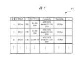
仕様管理テーブルSPTは、図5に示すように、入出力インタフェースにおける’仕様番号’、’製品名’、’メーカ’、’FCプロトコル’、’コマンドセット(Command Set)’、ならびに’トランスファレート(Transfer Rate)’から構成されている。As shown in Figure 5, the specification management table SPT is composed of the 'specification number', 'product name', 'manufacturer', 'FC protocol', 'command set', and 'transfer rate' for the input/output interface.
次に、本実施の形態における複合型計算機装置3の作用について説明する。Next, we will explain the operation of the
始めに、入出力インタフェーススイッチ7における接続変更時の管理技術について、図6のフローチャートを用いて説明する。First, the management technology used when changing connections in the input/
まず、統合管理サーバ2から出力された入出力インタフェースモジュール8の接続指示を管理サーバ5が受信する(ステップS101)。管理サーバ5は、統合管理サーバ2からの指示に基づいて、入出力インタフェーススイッチ構成テーブルIFT、およびサーバ構成管理テーブルSTを参照し、入出力インタフェースモジュール8に要求された条件リストJL(図6の右側上方の条件リストを参照)を作成する(ステップS102)。First, the
その後、unassigned状態入出力インタフェースモジュール管理テーブルUNT(図6の右側下方のテーブルを参照)から条件リストJLと同じ種別(たとえば、FC)の入出力インタフェースを選択する(ステップS103)。Then, an I/O interface of the same type (e.g., FC) as the condition list JL is selected from the unassigned state I/O interface module management table UNT (see the table in the lower right of Figure 6) (step S103).
続いて、unassigned状態入出力インタフェースモジュール管理テーブルUNTから条件リストJLと同じ仕様(たとえば、仕様’15’)の入出力インタフェースを選択し(ステップS104)、同様に、unassigned状態入出力インタフェースモジュール管理テーブルUNTから条件リストJLと同じプロトコル(たとえば、プロトコル’FC’)の入出力インタフェースを選択する(ステップS105)。Next, an I/O interface with the same specifications as the condition list JL (e.g., specification '15') is selected from the unassigned state I/O interface module management table UNT (step S104), and similarly, an I/O interface with the same protocol as the condition list JL (e.g., protocol 'FC') is selected from the unassigned state I/O interface module management table UNT (step S105).
そして、unassigned状態入出力インタフェースモジュール管理テーブルUNTから条件リストJLと同じ入出力装置が接続される入出力インタフェース(たとえば、ディスクアレイ装置1:図1のディスクアレイ装置42)を選択する(ステップS106)。 Then, an I/O interface (for example, disk array device 1:
ここで、図6の右側下方のunassigned状態入出力インタフェースモジュール管理テーブルUNTに示された入出力インタフェースモジュール8の接続関係は、図7に示すようになる。Here, the connection relationship of the I/
続いて、管理サーバ5は、入出力インタフェーススイッチ7に対して、選択された入出力インタフェースとプロセッサとの接続を指示する(ステップS107)。管理サーバ5は、入出力装置管理サーバ、およびネットワーク管理サーバに対し、選択した入出力インタフェースを用いた接続の設定を指示し(ステップS108)、unassigned続状態入出力インタフェースモジュール管理テーブル、および仕様管理テーブルSPTを更新する(ステップS109)。Then, the
ここで、入出力装置管理サーバは、入出力装置41〜4Nを管理するサーバであり、該入出力装置管理サーバは、入出力装置41〜4Nにそれぞれ接続されている。また、ネットワーク管理サーバは、ネットワークNt1〜Nt3を管理するサーバであり、ネットワークNt1〜Nt3にそれぞれ接続されている。 Here, the I/O device management server is a server that manages the I/O devices41 to4N and is connected to each of the I/O devices41 to4N . Also, the network management server is a server that manages the networks Nt1 to Nt3 and is connected to each of the networks Nt1 to Nt3.
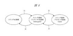
図8は、複合型計算機装置3における入出力インタフェースモジュール8の状態遷移図である。Figure 8 shows a state transition diagram of the input/
図8において、状態J1は、入出力インタフェースモジュール8の入出力インタフェースをはずしている状態から、入出力インタフェースを入出力インタフェーススイッチ7のポートに接続しているが、プロセッサモジュール6には未接続(unassigned)の状態に遷移した場合を示している。状態J2は、状態J1から、入出力インタフェースをプロセッサモジュール6に接続(use)した状態に遷移した場合を示している。In FIG. 8, state J1 shows a transition from a state in which the I/O interface of the I/
状態J3は、状態J2から、入出力インタフェースがプロセッサモジュール6と未接続(unassigned)の状態に遷移した場合を示しており、状態J4は、状態J3から、入出力インタフェースをモジュールからはずした状態に遷移した場合を示している。State J3 shows a transition from state J2 to a state in which the I/O interface is unassigned to the processor module 6, and state J4 shows a transition from state J3 to a state in which the I/O interface is disconnected from the module.
図9は、入出力インタフェース81〜8Nにおける状態遷移図である。 FIG. 9 is a state transition diagram in the input/
状態J5は、入出力インタフェースが複合型計算機装置2に未接続の状態から接続された状態に遷移したことを示し、状態J6は、入出力インタフェースが複合型計算機装置2に接続された状態から未接続の状態に遷移したことを示している。State J5 indicates that the input/output interface has transitioned from a state in which it is not connected to the
次に、図8、図9に示した状態J1〜J6における複合型計算機装置2の動作について、図10〜図15を用いて説明する。Next, the operation of the
図10は、図8の状態J1に遷移する際のフローチャートである。Figure 10 is a flowchart showing the transition to state J1 in Figure 8.
まず、新規の入出力インタフェースが入出力インタフェーススイッチ7に接続されると(ステップS201)、入出力インタフェーススイッチ7は、接続された入出力インタフェースの種別、スロット位置、識別子(MACアドレス、WWNなど)などの情報を収集し、それら収集した情報と管理サーバ5に新規の入出力インタフェースが接続されたこととを通知する(ステップS202)。First, when a new I/O interface is connected to the I/O interface switch 7 (step S201), the I/
続いて、管理サーバ5は、入出力インタフェーススイッチ7から接続された入出力インタフェースの固有情報を取得する(ステップS203)。管理サーバ5は、図5の仕様管理テーブルSPTを参照し、仕様識別子を取得する(ステップS204)。Then, the
その後、管理サーバ5は、入出力装置管理サーバ、およびネットワーク管理サーバから、入出力インタフェースモジュール8に接続可能な入出力装置の情報を取得する(ステップS205)。Then, the
そして、管理サーバ4は、新規に接続された入出力インタフェースを、図2の入出力インタフェーススイッチ構成テーブルIFTに追加する(ステップS206)。Then, the
図11は、図8の状態J4に遷移する際のフローチャートである。Figure 11 is a flowchart showing the transition to state J4 in Figure 8.
まず、入出力インタフェースが入出力インタフェーススイッチ7から外されると(ステップS301)、該入出力インタフェーススイッチ7は、管理サーバ5に入出力インタフェースの削除を通知する(ステップS302)。First, when an input/output interface is removed from the input/output interface switch 7 (step S301), the input/
その後、管理サーバ5は、外された入出力インタフェースを、図2の入出力インタフェーススイッチ構成テーブルIFTから削除し(ステップS303)、続いて、該入出力インタフェースを、図4のunassigned状態入出力インタフェースモジュール管理テーブルUNTから削除する(ステップS304)。Then, the
図12は、図9の状態J5に遷移する際のフローチャートである。Figure 12 is a flowchart showing the transition to state J5 in Figure 9.
新規の入出力装置が追加されると(ステップS401)、ネットワーク管理サーバ、または入出力管理サーバが管理サーバ5に対して新規の入出力装置が接続されてことを通知する(ステップS402)。When a new I/O device is added (step S401), the network management server or the I/O management server notifies the
管理サーバ5は、入出力装置管理サーバ、およびネットワーク管理サーバから新規の入出力装置に接続することができる入出力インタフェースの情報を取得し(ステップS403)、該入出力装置に接続可能な入出力インタフェースをunassigned状態入出力インタフェースモジュール管理テーブルUNT(図4)に追加する(ステップS404)。The
図13は、図9の状態J6に遷移する際のフローチャートである。Figure 13 is a flowchart showing the transition to state J6 in Figure 9.
入出力装置が取り外されると(ステップS501)、ネットワーク管理サーバ、あるいは入出力装置管理サーバは、管理サーバ5に対して入出力装置が削除されたことを通知する(ステップS502)。When the I/O device is removed (step S501), the network management server or the I/O device management server notifies the
続いて、管理サーバ5a、unassigned状態入出力インタフェースモジュール管理テーブルUNT(図4)から削除された入出力装置の項目の削除を行う(ステップS503)。Then, the management server 5a deletes the item of the deleted I/O device from the unassigned state I/O interface module management table UNT (Figure 4) (step S503).
図14は、図8の状態J2に遷移する際のフローチャートである。Figure 14 is a flowchart showing the transition to state J2 in Figure 8.
未接続の入出力インタフェースとプロセッサとが接続されると(ステップS601)、管理サーバ5は、その新しい接続関係の情報を入出力インタフェーススイッチ構成テーブルIFT(図2)に更新する(ステップS602)。When an unconnected I/O interface is connected to the processor (step S601), the
続いて、管理サーバ5は、新しく接続された入出力インタフェースに関する項目を図3のサーバ構成管理テーブルSTに追加し、更新し(ステップS603)、該当する入出力インタフェースに関する項目をunassigned状態入出力インタフェースモジュール管理テーブルUNT(図4)から削除する(ステップS604)。Then, the
図15は、図8の状態J3に遷移する際のフローチャートである。Figure 15 is a flowchart showing the transition to state J3 in Figure 8.
プロセッサから入出力インタフェースが切り離されると(ステップS701)、その新しい接続関係を入出力インタフェーススイッチ構成テーブルIFT(図2)に更新する(ステップS702)。When an I/O interface is disconnected from the processor (step S701), the new connection relationship is updated in the I/O interface switch configuration table IFT (Figure 2) (step S702).
続いて、管理サーバ5は、切り離し/接続された入出力インタフェースに関する項目をサーバ構成管理テーブルST(図3)に追加する(ステップS703)。その後、管理サーバ5は、入出力装置管理サーバ、およびネットワーク管理サーバから切り離された入出力インタフェースに接続可能な入出力装置の情報を取得し(ステップS704)、切り離された入出力インタフェースをunassigned状態入出力インタフェースモジュール管理テーブルUNTに追加する(ステップS705)。Then, the
図16は、管理サーバ5による図6に示した条件リストJLの作成方法を示した説明図である。Figure 16 is an explanatory diagram showing how the
条件リストJLは、図示するように、サーバ構成管理テーブルST、および入出力インタフェーススイッチ構成テーブルIFTから作成される。The condition list JL is created from the server configuration management table ST and the input/output interface switch configuration table IFT, as shown in the figure.
たとえば、ある入出力インタフェースに障害が発生すると、統合管理サーバ2からは、該入出力インタフェースの代替となる入出力インタフェースを選択するように要求がある。For example, if a failure occurs in a certain I/O interface, the
管理サーバ5は、この要求を受けると、サーバ構成管理テーブルST、および入出力インタフェーススイッチ構成テーブルIFTを参照し、障害が発生した入出力インタフェースと同じ条件となる入出力装置、入出力インタフェースの種別、仕様、および通信のプロトコルを必要な条件リストJLとして作成する。When the
なお、ここでは、ある入出力インタフェースに障害が発生した場合に条件リストJLを作成する場合について記載したが、たとえば、統合管理サーバ2から冗長ペアを要求された場合に条件リストJLを作成し、該条件リストJLに基づいて、冗長構成を構築するようにしてもよい。Note that, although the above describes the case where a condition list JL is created when a failure occurs in a certain input/output interface, it is also possible to create a condition list JL when a redundant pair is requested from the integrated
図17は、管理サーバ5による条件リストJLの作成時に用いられる入出力インタフェースモジュール互換性テーブルGTの一例を示す。Figure 17 shows an example of an I/O interface module compatibility table GT used when the
図16においては、条件リストJLを作成する際に仕様が同じ入出力インタフェースのみが条件リストJLにリストアップされているが、たとえば、図17に示すように、入出力インタフェースモジュール互換性テーブルGTを参照し、互換性のある仕様を有する入出力インタフェースの選択も行うようにしてもよい。In FIG. 16, when the condition list JL is created, only input/output interfaces with the same specifications are listed in the condition list JL. However, for example, as shown in FIG. 17, it is also possible to refer to the input/output interface module compatibility table GT and select input/output interfaces with compatible specifications.
図18は、統合管理サーバ2から、管理サーバ5に対する要求を送信する際の要求データのプロトコルを示す説明図である。Figure 18 is an explanatory diagram showing the protocol of the request data when sending a request from the integrated
要求データは、たとえば、テキスト形式によって送信され、構成変更、構成変更内容、およびシナリオ実行条件から構成されている。The request data is sent, for example, in text format and consists of configuration changes, configuration change details, and scenario execution conditions.
構成変更は、’config’などの接続構成を変更するコマンドであり、構成変更内容は、障害によるバスの切り替えなどの構成変更内容を示す。シナリオ実行条件は、たとえば、互換性のある入出力インタフェースの使用の良否などの各種の実行条件を示している。A configuration change is a command such as 'config' that changes the connection configuration, and the configuration change content indicates the configuration change content such as bus switching due to a failure. A scenario execution condition indicates various execution conditions, such as whether or not a compatible I/O interface is available.
図19は、複合型計算機装置3の他の構成例を示すブロック図である。Figure 19 is a block diagram showing another example configuration of a
この場合、複合型計算機装置3は、スイッチ管理CPU7aが新たに設けられており、その他の構成については、図1と同様となっている。In this case, the
スイッチ管理CPU7aは、管理サーバ5、および入出力インタフェーススイッチ7にそれぞれ接続されている。スイッチ管理CPU7aは、プロセッサと接続されていない入出力インタフェースとの接続を行い、該入出力インタフェースの識別子(図2)、仕様(図2)を決定するための固有のコンフィグレーション情報などを取得し、管理サーバ5にそれら取得した情報を送信する。The
それにより、本実施の形態によれば、入出力インタフェースモジュール8における管理のサポートが不要となり、管理コスト、および管理工数を大幅に省力化することができる。As a result, according to this embodiment, management support in the input/
また、障害時の代替の入出力インタフェースを複数のプロセッサによって共有することができるので、予備で持つ入出力インタフェースなどのハードウェアリソースを削減することができる。In addition, since an alternative I/O interface in the event of a failure can be shared by multiple processors, hardware resources such as spare I/O interfaces can be reduced.
以上、本発明者によってなされた発明を実施の形態に基づき具体的に説明したが、本発明は前記実施の形態に限定されるものではなく、その要旨を逸脱しない範囲で種々変更可能であることはいうまでもない。The invention made by the inventor has been specifically described above based on the embodiment, but it goes without saying that the invention is not limited to the above embodiment and can be modified in various ways without departing from the gist of the invention.
本発明の計算機システムにおける入出力インタフェースモジュールの管理方法は、複合型計算機装置における運用管理の省力化技術に適している。The method for managing input/output interface modules in a computer system of the present invention is suitable as a labor-saving technology for operational management in a multi-computer device.
1 計算機システム
2 統合管理サーバ
3 複合型計算機装置
41〜4N 入出力装置
5 管理サーバ
6 プロセッサモジュール
61〜6N プロセッサ
7 入出力インタフェーススイッチ
8 入出力インタフェースモジュール
81〜8N 入出力インタフェース
Nt1〜Nt3 ネットワーク
KT 構成管理テーブル
IFT 入出力インタフェーススイッチ構成テーブル
ST サーバ管理構成テーブル
UNT unassigned状態入出力インタフェースモジュール管理テーブル
SPT 仕様管理テーブル
JL 条件リスト
GT 入出力インタフェースモジュール互換性テーブルREFERENCE SIGNS
Claims (11)
Translated fromJapanese前記管理サーバは、
少なくとも前記入出力インタフェーススイッチにて接続された前記プロセッサモジュールと前記入出力インタフェースモジュールとの接続関係を管理する入出力インタフェーススイッチ構成テーブルと、
少なくとも個々のプロセッサと入出力装置の接続関係を含む前記複合型計算機装置の構成を管理するサーバ構成テーブルと、
少なくともいずれのプロセッサモジュールとも未接続である入出力インタフェースモジュールについての、接続対象とする入出力装置、入出力インタフェースの種別、仕様、および通信プロトコルを有する入出力インタフェースモジュール管理テーブルと、
少なくとも入出力インタフェースの種別毎の仕様を管理する仕様管理テーブルとを有し、
前記統合管理サーバからの入出力装置接続指示により、あるプロセッサモジュールに新たに接続する前記入出力インタフェースモジュールを選択する際に、前記統合管理サーバから取得した入出力装置接続指示に基づいて前記入出力インタフェーススイッチ構成テーブルと前記サーバ構成テーブルとを参照して接続する入出力装置、入出力インタフェースの種別、仕様、および通信プロトコルからなる条件リストを作成し、前記入出力インタフェースモジュール管理テーブルを参照して、前記入出力インタフェースモジュール管理テーブルにおける前記接続対象とする入出力装置、入出力インタフェースの種別、仕様、および通信プロトコルが前記条件リストに適合する入出力インタフェースモジュールを選択し、入出力インタフェーススイッチへプロセッサモジュールと入出力インタフェースモジュールとの接続変更を指示し、その接続変更の情報に基づいて前記入出力インタフェーススイッチ構成テーブルの更新を行うことを特徴とする入出力インタフェースモジュールの管理方法。 A method for managing an input/output interface module using a computer system including a composite computer device comprising a plurality of processor modules each equipped with a processor, a plurality of input/output interface modules, an input/output interface switch that enables connection between the processor modules and the input/output interface modules and arbitrarily determines a connection relationship between the input/output interface modules and the processor modules, and a managementserver that controls the input/output interface switch and manages the connection relationship between the input/output interface modules and the processors, an integrated management server connected to the management server and running integrated management software that determines a configuration of the composite computer device, and input/output devices connected directly to the input/output interface modules or via a network,
The management server includes:
an input/output interface switch configuration table for managing a connection relationship between the processor module and the input/output interface module connected at least by the input/output interface switch;
a server configuration table for managing the configuration of the composite computer system including at least the connection relationships between the individual processors and the input/output devices;
an I/O interface module management tablehaving, for an I/O interface module that is not connected to at least any processor module, an I/O device to be connected, an I/O interface type, a specification, and a communication protocol ;
a specification management table for managing at least the specifications for each type of input/output interface;
a management method for an input/output interface module, characterized in that, when selecting an input/output interface module to be newly connected to a processor module in response to an input/output device connection instruction from the integrated management server, the method refers tothe input/output interface switch configuration table and the server configuration table based on the input/output device connection instruction obtained from the integrated management server to create a condition list consisting of the input/output device to be connected, the type, specifications,and communication protocol of the input/output interface, refers to the input/output interface module management table to select an input/output interface module in the input/output interface module management table whose input/output device to be connected, the type, specifications, and communication protocol of the input/output interface conform to the condition list, instructs an input/output interface switch to change the connection between the processor module and the input/output interface module, and updates the input/output interface switch configuration table based on information about the connection change.
1つの前記入出力インタフェースモジュールが、前記入出力インタフェーススイッチへ新規に追加された場合、前記入出力インタフェーススイッチが前記入出力インタフェースモジュールの接続を認識して前記管理サーバへ通知し、
前記管理サーバは、
前記入出力インタフェースモジュールの新規接続を認識した際に、前記入出力インタフェーススイッチから前記入出力インタフェースモジュールの種別、仕様、識別子、電源状態などの情報を取得し、新規の前記入出力インタフェースモジュールを前記入出力インタフェーススイッチ構成テーブルに追加し、前記入出力インタフェースモジュールの仕様により仕様IDを選択して前記入出力インタフェーススイッチ構成テーブルに記録し、前記ネットワークの管理を行うネットワーク管理サーバ、および前記入出力装置の管理を行う入出力装置管理サーバから、前記入出力インタフェースモジュールに接続可能な前記入出力装置の情報を入手し、前記入出力インタフェースモジュール管理テーブルに記録することを特徴とする入出力インタフェースモジュールの管理方法。 2. The method for managing an input/output interface module according to claim 1, further comprising:
When one of the I/O interface modules is newly added to the I/O interface switch, the I/O interface switch recognizes the connection of the I/O interface module and notifies the management server;
The management server includes:
a management method for an input/output interface module, when a new connection of the input/output interface module is recognized, obtaining information such as the type, specifications, identifier, and power state of the input/output interface module from the input/output interface switch, adding the new input/output interface module to the input/output interface switch configuration table, selecting a specification ID based on the specifications of the input/output interface module and recording it in the input/output interface switch configuration table, obtaining information on the input/output devices that can be connected to the input/output interface module from a network management server that manages the network and an input/output device management server that manages the input/output devices, and recording the information in the input/output interface module management table.
前記入出力インタフェーススイッチに接続された1つの前記入出力インタフェースモジュールが前記入出力インタフェーススイッチから外された場合、
前記入出力インタフェーススイッチは、
前記入出力インタフェースモジュールの削除されたことを認識して前記管理サーバへ通知し、
前記管理サーバは、
前記入出力インタフェースモジュールの削除を認識すると、前記入出力インタフェーススイッチ構成テーブル、および前記入出力インタフェースモジュール管理テーブルから削除された前記入出力インタフェースモジュールの項目を削除することを特徴とする入出力インタフェースモジュールの管理方法。 3. The method for managing an input/output interface module according to claim 2, further comprising:
When one of the I/O interface modules connected to the I/O interface switch is removed from the I/O interface switch,
The input/output interface switch includes:
Recognizing that the input/output interface module has been deleted and notifying the management server;
The management server includes:
a management method for an input/output interface module, characterized in that, when the deletion of the input/output interface module is recognized, the entry of the deleted input/output interface module is deleted from the input/output interface switch configuration table and the input/output interface module management table.
1つの前記入出力装置が追加された場合、
前記管理サーバは、
前記ネットワーク管理サーバ、または前記入出力装置管理サーバから新しく追加された入出力装置に接続可能な入出力インタフェースモジュールの情報を取得し、前記入出力インタフェースモジュール管理テーブルに記録することを特徴とする入出力インタフェースモジュールの管理方法。 3. The method for managing an input/output interface module according to claim 1, further comprising:
When one of the I/O devices is added,
The management server includes:
A method for managing an input/output interface module, comprising obtaining information on an input/output interface module connectable to a newly added input/output device from the network management server or the input/output device management server, and recording the information in the input/output interface module management table.
1つの前記入出力装置が取り外された場合、
前記管理サーバは、
前記ネットワーク管理サーバ、および前記入出力装置管理サーバから削除された入出力装置の情報を取得し、削除された前記入出力装置に関する項目を前記入出力インタフェースモジュール管理テーブルから削除することを特徴とする入出力インタフェースモジュールの管理方法。 5. The method for managing an input/output interface module according to claim 2, further comprising:
When one of the I/O devices is removed,
The management server includes:
A method for managing an input/output interface module, comprising the steps of: obtaining information on a deleted input/output device from the network management server and the input/output device management server; and deleting an item relating to the deleted input/output device from the input/output interface module management table.
前記入出力インタフェーススイッチの接続変更において、前記プロセッサモジュールに未接続の入出力インタフェースモジュールとプロセッサとが接続された場合、
前記管理サーバは、
接続の変更に従って前記入出力インタフェーススイッチ構成テーブルを更新し、前記入出力インタフェースモジュール、および接続される前記入出力装置の項目について前記サーバ構成テーブルを更新し、前記入出力インタフェースモジュール管理テーブルから対象の入出力インタフェースモジュールを削除し、
前記プロセッサモジュールに接続されている入出力インタフェースモジュールを切り離す場合、
前記管理サーバは、
接続の変更に従って前記入出力インタフェーススイッチ構成テーブルを更新し、前記入出力インタフェースモジュール、および接続されている前記入出力装置の項目について前記サーバ構成テーブルを更新し、切り離された前記入出力インタフェースモジュールの接続可能な入出力装置の情報を収集し、変更を前記入出力インタフェースモジュール管理テーブルに追加することを特徴とする入出力インタフェースモジュールの管理方法。 6. The method for managing an input/output interface module according to claim 2, further comprising:
When the connection of the input/output interface switch is changed, an input/output interface module that is not connected to the processor module is connected to the processor,
The management server includes:
updating the I/O interface switch configuration table according to the change in connection, updating the server configuration table with respect to the entries of the I/O interface module and the connected I/O device, and deleting the target I/O interface module from the I/O interface module management table;
When an input/output interface module connected to the processor module is disconnected,
The management server includes:
A method for managing an I/O interface module, comprising: updating the I/O interface switch configuration table according to a change in connection; updating the server configuration table for entries of the I/O interface module and the connected I/O device; collecting information on connectable I/O devices of the disconnected I/O interface module; and adding the changes to the I/O interface module management table.
入出力インタフェースモジュールに障害が起きた場合、前記統合管理サーバは、前記管理サーバに対して、代替の入出力インタフェースモジュールをプロセッサに接続するというシナリオを要求し、
前記管理サーバは、
受け取ったシナリオを基に、障害が起きた入出力インタフェースモジュールと同じ入出力装置、および入出力インタフェースモジュールの種別、仕様、通信プロトコルを必要な条件リストとしてそれぞれ作成することを特徴とする入出力インタフェースモジュールの管理方法。 7. The method for managing an input/output interface module according to claim 2, further comprising:
When a failure occurs in an I/O interface module, the integrated management server requests the management server for a scenario in which an alternative I/O interface module is connected to a processor;
The management server includes:
A method for managing an I/O interface module, comprising the steps of: creating, based on a received scenario, a required condition list for an I/O device identical to that of the faulty I/O interface module, and the type, specifications, and communication protocol of the I/O interface module.
システム信頼性向上のために冗長構成をとるシステムを構築する際に、前記統合管理サーバは、前記管理サーバに対して、冗長ペアが構成できる入出力インタフェースモジュールをプロセッサに接続するというシナリオを要求し、
前記管理サーバは、
受け取ったシナリオを基に、入出力装置、ならびに入出力インタフェースモジュールの種別、仕様、通信プロトコルを必要な条件リストとしてそれぞれ作成することを特徴とする入出力インタフェースモジュールの管理方法。 8. The method for managing an input/output interface module according to claim 2, further comprising:
When constructing a system having a redundant configuration to improve system reliability, the integrated management server requests the management server for a scenario in which an I/O interface module capable of forming a redundant pair is connected to a processor;
The management server includes:
A method for managing an input/output interface module, comprising the steps of: creating a list of required conditions for the input/output device and the type, specifications, and communication protocol of the input/output interface module based on the received scenario.
前記管理サーバは、
予めすべての前記入出力インタフェースモジュールの互換性についての情報が記載された入出力インタフェースモジュール互換性テーブルを有し、前記入出力インタフェースモジュールを選択する際に、前記管理サーバが前記入出力インタフェースモジュール互換性テーブルを参照し、前記入出力インタフェースモジュールにおける仕様の情報から、異なる型式や異なるベンダであっても互換性がある前記入出力インタフェースモジュールであれば選択することを特徴とする入出力インタフェースモジュールの管理方法。 9. The method for managing an input/output interface module according to claim 2, further comprising:
The management server includes:
A method for managing input/output interface modules, comprising: an input/output interface module compatibility table in which information regarding the compatibility of all of the input/output interface modules is recorded in advance; and when selecting an input/output interface module, the management server refers to the input/output interface module compatibility table and selects an input/output interface module that is compatible based on specification information of the input/output interface module, even if it is a different model or a different vendor.
前記入出力インタフェースモジュールの識別子や固有のコンフィグレーション情報を取得する場合に、前記入出力インタフェーススイッチの制御により、前記入出力インタフェーススイッチに付属するスイッチ制御用プロセッサに前記入出力インタフェースモジュールを接続し、コンフィグレーション空間の情報、および半導体メモリに書き込まれた識別子の情報を取得し、前記管理サーバへ取得した情報を送付し、情報取得後は、前記入出力インタフェーススイッチの制御により、前記入出力インタフェースモジュールを未接続状態に戻すことを特徴とする入出力インタフェースモジュールの管理方法。 10. The method for managing an input/output interface module according to claim 2, further comprising:
A method for managing an input/output interface module, characterized in that, when obtaining an identifier and unique configuration information of the input/output interface module, the input/output interface module is connected to a switch control processor attached to the input/output interface switch under the control of the input/output interface switch, information on the configuration space and information on the identifier written in a semiconductor memory are obtained, the obtained information is sent to the management server, and after the information is obtained, the input/output interface module is returned to an unconnected state under the control of the input/output interface switch.
前記統合管理サーバから前記管理サーバへ送信されるシナリオの指示は、テキスト形式のインタフェースであることを特徴とする入出力インタフェースモジュールの管理方法。 11. The method for managing an input/output interface module according to claim 2, further comprising:
2. A method for managing an input/output interface module, wherein the scenario instructions transmitted from the integrated management server to the management server are in a text format interface.
Priority Applications (2)
| Application Number | Priority Date | Filing Date | Title |
|---|---|---|---|
| JP2004114011AJP4653965B2 (en) | 2004-04-08 | 2004-04-08 | How to manage I/O interface modules |
| US11/053,260US7389367B2 (en) | 2004-04-08 | 2005-02-09 | Method of managing I/O interface modules in a computer system |
Applications Claiming Priority (1)
| Application Number | Priority Date | Filing Date | Title |
|---|---|---|---|
| JP2004114011AJP4653965B2 (en) | 2004-04-08 | 2004-04-08 | How to manage I/O interface modules |
Publications (2)
| Publication Number | Publication Date |
|---|---|
| JP2005301488A JP2005301488A (en) | 2005-10-27 |
| JP4653965B2true JP4653965B2 (en) | 2011-03-16 |
Family
ID=35332973
Family Applications (1)
| Application Number | Title | Priority Date | Filing Date |
|---|---|---|---|
| JP2004114011AExpired - Fee RelatedJP4653965B2 (en) | 2004-04-08 | 2004-04-08 | How to manage I/O interface modules |
Country Status (2)
| Country | Link |
|---|---|
| US (1) | US7389367B2 (en) |
| JP (1) | JP4653965B2 (en) |
Families Citing this family (22)
| Publication number | Priority date | Publication date | Assignee | Title |
|---|---|---|---|---|
| US7321985B2 (en)* | 2004-02-26 | 2008-01-22 | International Business Machines Corporation | Method for achieving higher availability of computer PCI adapters |
| JP4624746B2 (en)* | 2004-09-10 | 2011-02-02 | 株式会社日立製作所 | Compound computer apparatus and management method thereof |
| CN100579146C (en)* | 2005-09-02 | 2010-01-06 | 深圳市东进通讯技术股份有限公司 | Module configuration management method in integrated telecommunication platform |
| JP4650278B2 (en)* | 2006-01-19 | 2011-03-16 | 株式会社日立製作所 | Complex information platform device and management method of complex information platform device |
| US8234330B2 (en)* | 2006-08-21 | 2012-07-31 | International Business Machines Corporation | Programmatically managing connections between servers and clients |
| JP5330268B2 (en)* | 2007-02-12 | 2013-10-30 | ゴア エンタープライズ ホールディングス,インコーポレイティド | Stringed instrument cable |
| JP5066978B2 (en)* | 2007-03-30 | 2012-11-07 | 日本電気株式会社 | Information processing apparatus fault processing method and information processing apparatus |
| JP5080140B2 (en)* | 2007-06-13 | 2012-11-21 | 株式会社日立製作所 | I/O device switching method |
| US8161079B2 (en)* | 2007-10-15 | 2012-04-17 | International Business Machines Corporation | Acquisition and expansion of storage area network interoperation relationships |
| JP5216336B2 (en) | 2008-01-23 | 2013-06-19 | 株式会社日立製作所 | Computer system, management server, and mismatch connection configuration detection method |
| JP4802207B2 (en) | 2008-04-23 | 2011-10-26 | 株式会社日立製作所 | Information processing system control method, information processing system, and program |
| JP4571203B2 (en)* | 2008-05-09 | 2010-10-27 | 株式会社日立製作所 | Management server and cluster management method in information processing system |
| JP5380978B2 (en)* | 2008-09-26 | 2014-01-08 | 富士通株式会社 | Transmission apparatus, transmission apparatus control method, and transmission apparatus control program |
| JP4727714B2 (en)* | 2008-12-05 | 2011-07-20 | 株式会社日立製作所 | Server failover control method and apparatus, and computer system group |
| US9229886B2 (en) | 2010-04-30 | 2016-01-05 | Hewlett Packard Enterprise Development Lp | Management data transfer between processors |
| US9292469B2 (en) | 2010-06-01 | 2016-03-22 | Hitachi, Ltd. | I/O device management method, computer system, and I/O device management program product |
| JP5706116B2 (en)* | 2010-09-06 | 2015-04-22 | 日本電気通信システム株式会社 | Communication device using serial transmission backplane and connection management method thereof |
| JP6014527B2 (en)* | 2013-03-26 | 2016-10-25 | 株式会社エヌ・ティ・ティ・データ | Machine management system, management server device, and program |
| US10601661B2 (en) | 2015-06-22 | 2020-03-24 | Arista Networks, Inc. | Tracking state of components within a network element |
| JP6874590B2 (en)* | 2017-08-14 | 2021-05-19 | 富士通株式会社 | Information processing system, management device, control method of information processing system |
| US11983054B2 (en)* | 2022-10-04 | 2024-05-14 | Dell Products L.P. | Systems and methods for granular and scalable subsystem power controls, fault handling, and field-replaceable unit isolation in a modular architecture |
| WO2025029948A2 (en)* | 2023-08-01 | 2025-02-06 | MTS IP Holdings Ltd | Multi-node server unit |
Family Cites Families (5)
| Publication number | Priority date | Publication date | Assignee | Title |
|---|---|---|---|---|
| JPH11328093A (en) | 1994-01-11 | 1999-11-30 | Hitachi Ltd | I / O device information management system for multi-computer system |
| JP3843713B2 (en)* | 1999-08-27 | 2006-11-08 | 株式会社日立製作所 | Computer system and device allocation method |
| JP4404493B2 (en) | 2001-02-01 | 2010-01-27 | 日本電気株式会社 | Computer system |
| JP3848587B2 (en)* | 2002-03-15 | 2006-11-22 | 株式会社日立製作所 | Information processing apparatus and communication path selection method |
| US7415551B2 (en)* | 2003-08-18 | 2008-08-19 | Dell Products L.P. | Multi-host virtual bridge input-output resource switch |
- 2004
- 2004-04-08JPJP2004114011Apatent/JP4653965B2/ennot_activeExpired - Fee Related
- 2005
- 2005-02-09USUS11/053,260patent/US7389367B2/ennot_activeExpired - Fee Related
Also Published As
| Publication number | Publication date |
|---|---|
| US7389367B2 (en) | 2008-06-17 |
| US20050267963A1 (en) | 2005-12-01 |
| JP2005301488A (en) | 2005-10-27 |
Similar Documents
| Publication | Publication Date | Title |
|---|---|---|
| JP4653965B2 (en) | How to manage I/O interface modules | |
| JP6317856B2 (en) | Smooth controller change in redundant configuration between clusters | |
| US6553408B1 (en) | Virtual device architecture having memory for storing lists of driver modules | |
| TWI403891B (en) | Active-active failover for a direct-attached storage system | |
| US7085961B2 (en) | Redundant management board blade server management system | |
| US6598174B1 (en) | Method and apparatus for storage unit replacement in non-redundant array | |
| US6571354B1 (en) | Method and apparatus for storage unit replacement according to array priority | |
| CN100480979C (en) | Storage system and storage control method | |
| US6640278B1 (en) | Method for configuration and management of storage resources in a storage network | |
| US7444541B2 (en) | Failover and failback of write cache data in dual active controllers | |
| US8458432B2 (en) | Computer system, storage system and method for controlling power supply based on logical partition | |
| US6886054B2 (en) | Storage system, switch, storage medium having a program, storage system management method to manage data frames output from a switch to storage locations using correspondence data in a switch | |
| CN101651559B (en) | A method for failover of storage services in a dual-controller storage system | |
| JP4338068B2 (en) | Storage system | |
| US20130111471A1 (en) | Compute and storage provisioning in a cloud environment | |
| US7577812B2 (en) | Storage controlling unit | |
| US20070226415A1 (en) | Using OOB to Provide Communication in a Computer Storage System | |
| JP4414961B2 (en) | Management method by management server, management server, computer system, and management program | |
| IE20000203A1 (en) | Storage domain management system | |
| US20120284435A1 (en) | Zone group manager virtual phy | |
| JP2009199584A (en) | Method and apparatus for managing hdd's spin-down and spin-up in tiered storage system | |
| JP2008228150A (en) | Switch device, and frame switching method and program thereof | |
| US20140304532A1 (en) | Server systems having segregated power circuits for high availability applications | |
| USRE46770E1 (en) | Computer managing method | |
| JP3765198B2 (en) | Computer system |
Legal Events
| Date | Code | Title | Description |
|---|---|---|---|
| A621 | Written request for application examination | Free format text:JAPANESE INTERMEDIATE CODE: A621 Effective date:20061214 | |
| A977 | Report on retrieval | Free format text:JAPANESE INTERMEDIATE CODE: A971007 Effective date:20090330 | |
| A131 | Notification of reasons for refusal | Free format text:JAPANESE INTERMEDIATE CODE: A131 Effective date:20090519 | |
| A02 | Decision of refusal | Free format text:JAPANESE INTERMEDIATE CODE: A02 Effective date:20100105 | |
| A521 | Request for written amendment filed | Free format text:JAPANESE INTERMEDIATE CODE: A523 Effective date:20100402 | |
| A911 | Transfer to examiner for re-examination before appeal (zenchi) | Free format text:JAPANESE INTERMEDIATE CODE: A911 Effective date:20100412 | |
| A131 | Notification of reasons for refusal | Free format text:JAPANESE INTERMEDIATE CODE: A131 Effective date:20100727 | |
| A521 | Request for written amendment filed | Free format text:JAPANESE INTERMEDIATE CODE: A523 Effective date:20100924 | |
| TRDD | Decision of grant or rejection written | ||
| A01 | Written decision to grant a patent or to grant a registration (utility model) | Free format text:JAPANESE INTERMEDIATE CODE: A01 Effective date:20101124 | |
| A01 | Written decision to grant a patent or to grant a registration (utility model) | Free format text:JAPANESE INTERMEDIATE CODE: A01 | |
| A61 | First payment of annual fees (during grant procedure) | Free format text:JAPANESE INTERMEDIATE CODE: A61 Effective date:20101220 | |
| R150 | Certificate of patent or registration of utility model | Free format text:JAPANESE INTERMEDIATE CODE: R150 | |
| FPAY | Renewal fee payment (event date is renewal date of database) | Free format text:PAYMENT UNTIL: 20131224 Year of fee payment:3 | |
| LAPS | Cancellation because of no payment of annual fees |