JP4653822B2 - Dental care support system based on image recognition - Google Patents
Dental care support system based on image recognitionDownload PDFInfo
- Publication number
- JP4653822B2 JP4653822B2JP2008144017AJP2008144017AJP4653822B2JP 4653822 B2JP4653822 B2JP 4653822B2JP 2008144017 AJP2008144017 AJP 2008144017AJP 2008144017 AJP2008144017 AJP 2008144017AJP 4653822 B2JP4653822 B2JP 4653822B2
- Authority
- JP
- Japan
- Prior art keywords
- patient
- operator
- image
- surgeon
- medical
- Prior art date
- Legal status (The legal status is an assumption and is not a legal conclusion. Google has not performed a legal analysis and makes no representation as to the accuracy of the status listed.)
- Expired - Fee Related
Links
Images


Landscapes
- Dental Tools And Instruments Or Auxiliary Dental Instruments (AREA)
Description
Translated fromJapanese本発明は、歯科診療支援システムに関し、詳しくは、歯科診療エリアの診療ユニット、患者、術者の配置・位置を画像認識することにより、歯科診療ユニットの各部及び装置を最適ポジションに自動配置して診療行為を支援するシステムに関する。 The present invention relates to a dental care support system, and more particularly, by automatically recognizing the placement and position of a medical unit, a patient, and a surgeon in a dental care area, the respective parts and devices of the dental care unit are automatically arranged at an optimum position. The present invention relates to a system that supports medical practice.
歯科診療においては、患者の導入時や診察時には、診療ユニットのテーブルやチェアーの移動を術者がその都度行っていた。また、術者が診療位置にテーブルをセットする際に、あらかじめ診療しやすい位置を歯科診療ユニットの可動機構に記憶させておき、手動で動作方向に押すと所定位置まで移動させるユニットや、可動機構に駆動部を備え、スイッチの操作により診療位置まで移動させる自動機構付の診療ユニットがあるが、これらの自動セット機構では歯科診療ユニットの可動機構に駆動装置と共に、位置検出センサーを備えて動作を制御する必要があるため、信号機構が複雑となっていた。 In dental practice, the surgeon moves the table and chair of the medical unit each time a patient is introduced or examined. In addition, when the operator sets the table at the medical position, a position that allows easy medical treatment is stored in advance in the movable mechanism of the dental medical unit, and the unit can be moved to a predetermined position when manually pressed in the operation direction. There is a medical unit with an automatic mechanism that moves to the medical position by operating the switch.In these automatic setting mechanisms, the movable mechanism of the dental medical unit is equipped with a drive and a position detection sensor. The signal mechanism is complicated because it needs to be controlled.
テーブル等の歯科診療器具保持手段を治療に適した位置に自動的に移動させる従来の装置は、術者(ドクターまたは歯科衛生士)用椅子の位置に対応させて予め記憶手段に記憶させた診療位置に対応させた最適位置まで移動させる構成となっている(例えば、特許文献1参照)。 A conventional device that automatically moves a dental instrument holding means such as a table to a position suitable for treatment is a medical device stored in advance in a storage means corresponding to the position of a chair for an operator (doctor or dental hygienist). It is configured to move to an optimum position corresponding to the position (see, for example, Patent Document 1).
しかしながら、従来の装置では、患者導入時には、診療ユニットの各部(テーブルなど)を患者が着座するための移動の際に接触しない位置まで移動させる必要があった。また、自動セット機構のスイッチで、予め記憶させた最適診療位置までテーブルを移動させる方法では、術者の診療位置にずれがあっても自動修正ができないため、手動で修正を行う必要があった。 However, in the conventional apparatus, when the patient is introduced, it is necessary to move each part (table or the like) of the medical unit to a position where it does not come into contact when the patient is seated. In addition, in the method of moving the table to the optimal medical position stored in advance with the switch of the automatic setting mechanism, automatic correction is not possible even if there is a deviation in the medical position of the operator, so it was necessary to perform correction manually .
また、診療時のテーブルの設定位置は、術者がドクターチェアに着座した状態で肘を軽く曲げた高さに位置し、容易に手の届く距離にセットすることが望ましいが、術者の体型(背の高さ、手の長さなどの体格)によって最適なテーブル設定位置に大きな違いが発生する。このため、術者用椅子からの距離だけでテーブルの設定位置を判断して移動させても再度手動で調整する手間がかかる問題があった。しかも、複数の術者(ドクター、歯科衛生士)が同一診療ユニットに対して交代する場合、術者の体型個人差のために必ず調整しなければならない煩雑さがあった。 In addition, it is desirable to set the table at the time of medical treatment at the height where the elbow is lightly bent while the operator is seated on the doctor chair, and it should be set at a distance that can be easily reached. Depending on (physique such as height and hand length), there will be a big difference in the optimal table setting position. For this reason, there is a problem that it takes time and effort to manually adjust again even if the setting position of the table is determined and moved only by the distance from the operator chair. In addition, when a plurality of surgeons (doctors, dental hygienists) are changed with respect to the same medical care unit, there is a trouble that must be adjusted due to individual differences in the body shape of the surgeon.
また、これらの歯科ユニットの各部分を自動移動させる際に、移動する部分が患者や術者に接触する恐れがあるため、スイッチ操作の都度、衝突事故が起きないか確認し、監視していなければならなかった。 Also, when automatically moving each part of these dental units, the moving part may come into contact with the patient or the operator. I had to.
このような歯科診療ユニットの自動動作機構では、可動部分の制御のため、その制御信号伝達の配線が多くなり、可動部分の断線・誤動作、インスツルメントの誤作動などが発生しやすい。このため、可能な限り単純かつ安全な制御機構とすることが望まれていた。 In such an automatic operation mechanism of the dental care unit, control signal transmission wiring increases because of control of the movable part, and disconnection / malfunction of the movable part, malfunction of the instrument, etc. are likely to occur. For this reason, it has been desired to make the control mechanism as simple and safe as possible.
本発明は、このような従来の問題を考慮してなされたものであり、歯科診療ユニットの各装置の位置、患者および術者の存在とその位置をリアルタイムに認識して、患者の導入、診療開始、診療終了に対応して歯科診療ユニットの所定装置をそれぞれの最適位置に移動させる画像認識による歯科診療支援システムを提供することを課題とする。 The present invention has been made in consideration of such conventional problems, and recognizes the position of each device of the dental care unit, the presence of the patient and the operator, and the position thereof in real time, and introduces and cares for the patient. It is an object of the present invention to provide a dental care support system based on image recognition that moves a predetermined device of a dental care unit to each optimum position in response to start and end of medical care.
また、術者が選択した診療器具(インスツルメント類、その他の器具)の固体判別により、重複使用のロックや、ホースの送り出し、巻き取りを自動的に行い歯科診療行為を支援することを課題とする。 In addition, it is a challenge to support dental practice by automatically distinguishing the use of medical instruments (instruments, other instruments) selected by the surgeon and automatically locking and releasing hoses and winding them up. And
上記課題を達成するため、請求項1の発明の画像認識による歯科診療支援システムは、患者が着座する診療チェアを含む歯科診療ユニットならびに術者及び補助者の診察椅子近傍における診療エリアの画像情報を取得する一つまたは複数のカメラと、カメラからの画像情報に基づいて歯科診療ユニットにおける各装置の位置及び患者、術者の存在並びにその位置をリアルタイムに認識する認識手段と、術者の顔画像を記録した術者画像情報と、前記認識手段が術者の存在を認識したとき、前記カメラからの術者の顔画像と前記術者画像情報の顔画像とをパターンマッチングして術者識別を行う術者識別手段と、術者識別手段が識別した術者の診療スタイルに合わせた最適な位置に歯科診療ユニットにおける所定の装置を移動させるポジション制御手段とを備え、前記認識手段は前記カメラからの画像を一定時間間隔で取得し、前後画像を比較して歯科診療ユニット周辺の背景を監視し、その差分画像から動的な変化を抽出し、前記動的な変化が術者が着座する治療ポジションエリアの周辺か否かを判別し、前記認識手段が治療ポジションエリア周辺と判別したとき、前記術者識別手段が前記術者識別を行うことを特徴とする。In order to achieve the above object, a dental care support system based on image recognition according to the first aspect of the present invention provides image information of a dental care unit including a medical chair on which a patient is seated and a medical care area in the vicinity of a doctor and an assistant's medical chair. One or a plurality of cameras to be acquired, the position of each device in the dental care unit and the presence of the patient and the operator, and the position of the operator in real time based on image information from the camera,and the operator's face image And when the recognition means recognizes the presence of the operator, the operator's face image from the camera and the face image of the operator image information are pattern-matched to identify the operator. position is movedand the operator identification means, the combined optimal position practice style of the operator that the operator identification means has identified the predetermined device in a dental treatment unitfor And a controlmeans, the recognition means acquires the image from the camera at predetermined time intervals, to monitor the background around the dental treatment unit compares the image before and after extracting the dynamic changes from the difference image Determining whether or not the dynamic change is around the treatment position area where the operator is seated, and when the recognition means determines that the treatment position area is around, the operator identification means performs the operator identification It is characterized by.
この発明によれば、歯科診療ユニットの可動可能な各装置がどのような位置・状態にセットされているかをリアルタイムに把握することができる。また、診療エリアをリアルタイムに認識することにより、患者、術者及び補助者の存在と位置から診療過程(患者導入、診療開始、診療終了等)を認識することができる。さらに、リアルタイムに認識した画像情報と、一定時間前に認識した画像情報との差分から診療ユニットの各部の移動、患者、術者の移動を認識する動作認識を可能とすることができる。これらの状態認識と動作認識とにより、従来では術者または補助者が行っていた歯科診療ユニットの操作作業を自動化して支援することができる。 According to the present invention, it is possible to grasp in real time what position and state each movable device of the dental care unit is set to. Further, by recognizing the medical treatment area in real time, the medical treatment process (patient introduction, medical treatment start, medical treatment end, etc.) can be recognized from the presence and position of the patient, the operator, and the assistant. Furthermore, it is possible to recognize the movement of each part of the medical treatment unit and the movement of the patient and the operator from the difference between the image information recognized in real time and the image information recognized a predetermined time ago. With these state recognition and motion recognition, it is possible to automate and support the operation operation of the dental care unit that has been performed by an operator or an assistant.
また、この発明では、患者が診療チェアーに着座し、術者が診療ポジションに位置したことを認識し、テーブル、アシスタントハンガー等を診療動作に最適な位置に移動させる操作を自動的に行うことができる。このため、術者は余分な作業に煩わされることなく、患者の観察、説明、対話に専念して診療行為に入ることができる。 Further, in the present invention, it is possible to recognize that the patient is seated in the medical chair and the operator is in the medical position, and to automatically move the table, assistant hanger, etc. to the optimal position for the medical operation. it can. For this reason, the surgeon can concentrate on the observation, explanation, and dialogue of the patient and enter the medical practice without being bothered by extra work.
さらに、この発明では、術者識別手段を備えることにより、診療ポジションの術者を識別し、予め記憶させておいた術者ごとの診療スタイルに合わせた最適な位置に、診療ユニットの各装置を移動させることができる。予め術者の顔画像と、その術者の診療スタイルに合わせたテーブルセット位置を記憶させておくことにより、複数の術者が診療する歯科診療所においても、術者ごとに最適な装置のポジションを自動的にセットすることができる。 Further, according to the present invention, by providing the operator identification means, each operator of the medical unit is placed at an optimal position in accordance with the medical style for each operator that has been stored in advance. Can be moved. By storing the face image of the surgeon in advance and the table set position that matches the surgeon's treatment style, the optimal device position for each surgeon can be obtained even in a dental clinic where multiple surgeons are treated. Can be set automatically.
請求項2の発明の画像認識による歯科診療支援システムは、患者が着座する診療チェアを含む歯科診療ユニットならびに術者及び補助者の診察椅子近傍における診療エリアの画像情報を取得する一つまたは複数のカメラと、カメラからの画像情報に基づいて歯科診療ユニットにおける各装置の位置及び患者、術者の存在並びにその位置をリアルタイムに認識する認識手段と、術者の顔画像を記録した術者画像情報と、患者の顔画像を記録した患者画像情報と、前記認識手段が術者の存在を認識したとき、前記カメラからの術者の顔画像と前記術者画像情報の顔画像とをパターンマッチングして術者識別を行う術者識別手段と、前記認識手段が患者の存在を認識したとき、前記カメラからの患者の顔画像と前記患者画像情報の顔画像とをパターンマッチングして患者識別を行う患者識別手段と、術者識別手段が識別した術者の診療スタイルに合わせた最適な位置に歯科診療ユニットにおける所定の装置を移動させるポジション制御手段とを備え、前記認識手段は前記カメラからの画像を一定時間間隔で取得し、前後画像を比較して歯科診療ユニット周辺の背景を監視し、その差分画像から動的な変化を抽出し、前記動的な変化が術者が着座する治療ポジションエリアの周辺か否か及び患者が着座するチェアー周辺か否かを判別し、前記認識手段が治療ポジションエリア周辺と判別したとき、前記術者識別手段が前記術者識別を行い、前記認識手段が患者が着座するチェアー周辺と判別したとき、前記患者識別手段が前記患者識別を行うことを特徴とする。The dental care support system based on image recognition according to the invention of claim 2 is a dental care unit including a medical chair on which a patient is seated, and one or a plurality of image information of a medical care area in the vicinity of a medical chair of an operator and an assistant. Camera, recognition means for recognizing in real time the position of each device in the dental care unit and the presence of the patient and the operator and the position thereof based on the image information from the camera, andoperator image information recording the operator's face image Pattern matching between the patient image information in which the patient's face image is recorded and the operator's face image from the camera and the face image of the operator image information when the recognition means recognizes the presence of the operator. The operator identification means for performing the operator identification, and when the recognition means recognizes the presence of the patient, the patient face image from the camera and the face image of the patient image information are patterned. Patient recognition means for performing patient identification by matching, and position control means for moving a predetermined device in the dental care unit to an optimum position in accordance with the treatment style of the surgeon identified by the surgeon identification means, the recognition The means acquires images from the camera at regular time intervals, compares the front and back images, monitors the background around the dental care unit, extracts dynamic changes from the difference images, and the dynamic changes It is determined whether the patient is sitting around the treatment position area and whether the patient is sitting around the chair, and when the recognizing unit determines that the patient is sitting around the treatment position area, the operator identifying unit performs the operator identification. And when the recognition means discriminates the vicinity of the chair where the patient is seated, the patient identification means performs the patient identification.
この発明では、患者識別手段を備えることにより、患者個人を識別することができる。そして、診療チェアーに着座した患者個人を識別し、歯科診療管理サーバから患者の診療記録を読み出して表示することにより、治療経過の確認や、患者に対する診療内容の説明を行うことができる。 In the present invention, the patient individual can be identified by providing the patient identifying means. Then, by identifying the individual patient sitting on the medical chair and reading and displaying the patient's medical record from the dental medical management server, it is possible to check the treatment progress and explain the medical treatment contents for the patient.
本発明によれば、歯科診療ユニットの各装置の位置、患者および術者の存在とその位置をリアルタイムに認識し、患者の導入、診療開始、診療終了に対応して歯科診療ユニットの所定装置をそれぞれの最適位置に移動させることができる。このため、診療行為の流れをスムーズに効率よく行うことができる。特に、複雑な制御装置を歯科診療ユニットに設けることなく自動移動が可能となる。また、術者が選択した診療器具(インスツルメント類、その他の器具)の固体判別により、重複使用のロックや、ホースの送り出し、巻き取りを自動的に行い術者の歯科診療行為を支援することができる。 According to the present invention, the position of each device of the dental medical unit, the presence of the patient and the operator, and the position thereof are recognized in real time, and the predetermined device of the dental medical unit is set in response to the introduction of the patient, the start of medical treatment, and the end of the medical treatment. It can be moved to each optimum position. For this reason, the flow of medical treatment can be performed smoothly and efficiently. In particular, automatic movement is possible without providing a complicated control device in the dental care unit. In addition, based on the individual discrimination of the medical instruments (instruments, other instruments) selected by the surgeon, it automatically locks for duplicate use, sends out the hose, and winds up to support the surgeon's dental practice. be able to.
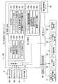
以下、本発明を図示する実施の形態につき具体的に説明する。図1は、本発明の一実施の形態における画像認識による歯科診療支援システムの構成を示すブロック図である。 DETAILED DESCRIPTION OF THE PREFERRED EMBODIMENTS Embodiments of the present invention will be specifically described below. FIG. 1 is a block diagram showing a configuration of a dental care support system based on image recognition according to an embodiment of the present invention.
この実施の形態の画像認識による歯科診療支援システム100は、カメラ10と、診療ユニットまたはその近傍に患者から視認可能な位置に設けた表示装置11と、画像認識・制御コンピュータ20と、歯科診療ユニット動作制御装置30と、院内LAN40を介して接続された歯科診療管理サーバ50とから構成されている。 The dental
診療ユニット動作制御装置30には、診療チェア昇降・背板傾動動作部31、テーブル移動動作部32、インスツルメント制御動作部33、アシスタントハンガー移動動作部34、無影灯移動動作部35が接続されることにより、これらの動作部が制御される。なお、画像認識・制御コンピュータ20及び診療ユニット動作制御装置30は診療ユニット1台ごとに備える構成を図示したが、複数の診療ユニットと接続して制御させる構成とすることも可能である。 Connected to the medical unit operation control device 30 are a medical chair raising / lowering / backboard
カメラ10は、外部接続ポート21に接続されることにより、撮影したデジタル画像を画像認識・制御コンピュータ20がリアルタイムで取得することを可能としている。この実施の形態では、下向きに設けられることにより診療エリアを水平視する第1のカメラ10aと、治療エリアを正面視する向きに設けた第2のカメラ10bと、診療ユニットの側面を水平に視認できる位置に設けられた第3のカメラ10cとを備える。 The
画像認識・制御コンピュータ20は、外部接続ポート21と、認識制御プログラムがインストールされた認識制御部22と、認識制御に必要な装置各部のポジション画像や、術者・患者の顔画像、術者ごとの最適ポジションを含む情報を記憶した記憶部23とから構成されている。 The image recognition / control computer 20 includes an
前記認識制御部22は、カメラから取得した画像情報から歯科診療ユニットの各部あるいは人物を識別する認識手段22aと、術者の個人識別を行う術者識別手段22bと、患者の個人識別を行う患者識別手段22cと、術者が使用しているインスツルメントを識別するインスツルメント判別手段22dと、診療段階を判断して最適ポジションに診療ユニットの各部を移動させるポジション制御手段22eと、患者個人識別に基づきその診療記録を表示装置(ディスプレイ)11に表示させる表示手段22fと、使用禁止器具の誤動作を制御するインスツルメントロック手段22gと、術者が使用中のインスツルメントホースを制御するインスツルメントホース制御手段22hと、記憶部23に術者や患者の顔画像情報を予め登録しておくための術者・患者画像記録手段22iと、術者個人の体格、好みに合わせた診療時の装置配置の画像、相対位置情報を記録する術者最適ポジション記録手段22jとを少なくとも備える。 The recognition control unit 22 includes a
また、前記記憶部23は、歯科診療ユニットの可動可能な各部について可動範囲画像を記録したユニット可動範囲画像情報23aと、術者画像情報23bと、患者画像情報23cと、最適ポジション情報23dとを備える。 Further, the storage unit 23 stores unit movable
ユニット可動範囲画像情報23aは、チェアーの背板の可動範囲(傾き)、テーブルの可動範囲、アシスタントハンガーの可動範囲、チェアーの上下(昇降)、背板の傾き範囲のモデル画像情報(可動状態の位置を一定間隔ごとの画像とした位置パターン画像)を記録したもので、前記認識手段22aが取得した画像と、モデル画像情報とを比較(パターンマッチング)することにより各部の位置を把握するために用いる情報である。 The unit movable
術者画像情報23bは、所属する術者の顔画像を記録したもので、前記術者認識手段22bが診療ポジションに着座した術者(ドクターや歯科衛生士)の顔画像と、登録された顔画像情報とを比較して術者個人認識を行うために用いる情報である。なお、治療ポジションエリアL内の顔画像であれば、立位診療を行う術者の顔画像の個人認識も可能である。 The
患者画像情報23cは、診療を受付けた患者の顔画像の記録であって、初診時にカメラで取得した患者の顔画像を歯科診療管理サーバ50に備え、院内LAN40を介して術者・患者画像記録手段22iにより登録しておく。また再診時には最新の顔画像に更新して記録することにより、診療ユニットに着座した患者の顔画像と、登録された患者顔画像とを比較し、患者識別手段22cが患者個人を識別するためのものである。 The
最適ポジション情報23dは、術者個人ごとの診療ポジションと、そのポジションに対応する歯科診療ユニットの各部の最適配置の画像または位置情報(パターン)を登録した情報である。この場合、術者の診療ポジションは、治療内容によって治療ポジションエリアLの範囲内で複数のポジションを採る場合がある。また、チェアー背板を倒し患者を完全水平にしたときの口腔位置を中心に何時の方向に術者が向いて診療行為を行うかにより、術者個人ごとにそれぞれのパターンの最適配置を登録しておく。 The
図2は、カメラの配置を示す正面図である。図に示すように、歯科診療ユニット1は、患者を着座させ背板17aを倒すことにより口腔の診療を行うチェアー17、このチェアー17の昇降や診療器具の動作制御を行うフットペダル18、チェアー17と共に昇降するように支持された診療器具を載置するテーブル13、テーブル13の下部に取り付けられたインスツルメントハンガー15、このハンガー15に保持されたインスツルメント16、インスツルメントホース16a、表示装置11、無影灯12などから構成されている。 FIG. 2 is a front view showing the arrangement of the cameras. As shown in the figure, the dental care unit 1 is a
ここで、主な可動可能である部分は、無影灯12、テーブル13、インスツルメントハンガー15、アシスタントハンガー14、背板17a及び、チェアー17である。なお、この実施の形態の歯科診療ユニット1は、チェアー17の昇降に伴って各部も昇降する構造となっている。 Here, the main movable parts are the
カメラ10は、診療エリアKの天井又は支柱に下向きに設けた第1のカメラ10aと、無影灯12などの支持ポールに治療ポジションエリアLを正面視する向きに設けた第2のカメラ10bと、壁面または歯科診療ユニットの側面を水平に視認できる位置に設けられた第3のカメラ10cとの3つのカメラを備えている。そして、第1のカメラ10aからの画像によって各部の平面での位置や人物の存在を認識可能とし、着座した患者の顔や術者の顔画像を第2のカメラ10bによって認識可能とし、チェアーの昇降状態や背板の傾き、各部の垂直位置を第3のカメラ10cによって認識する。 The
第3のカメラは、テーブル13やアシスタントハンガー14などがチェアー17に連動して昇降しないタイプの歯科診療ユニットの場合、テーブルなどの上下方向の移動を制御するための画像認識を行う。 The third camera performs image recognition for controlling the vertical movement of the table or the like when the table 13 or the
図3は、カメラの別の配置を示す側面図である。なお、図2と同じ装置については、同一の符号によって対応させてある。この実施の形態では、首振り機能(自動パン・チルト機能)付のカメラ10を無影灯12の先端部に配置し、無影灯12の支持アーム12a、12b、12c、12d、12eをそれぞれの支持アームの駆動モータM3、M4、M5、M6、M7によって回動させてカメラ10を所定の位置に移動させる。これにより、上述した第1のカメラ、第2のカメラの機能を備えたものとすることができる。 FIG. 3 is a side view showing another arrangement of the cameras. The same devices as those in FIG. 2 are associated with the same reference numerals. In this embodiment, a
カメラ位置Aは、各部の平面での位置や人物の存在を認識可能とする第1のカメラ10aに代わる位置であり、カメラ位置Bは、着座した患者の顔や術者の顔画像を認識可能とする第2のカメラ10bに代わる位置であり、カメラ位置Cは、患者の口腔を中心とした治療エリアNを認識する画像を取得して、術者の使用中のインスツルメントなどを識別するのに適した位置である。 The camera position A is a position in place of the
次に、認識手段22aに関する技術について述べる。天井に設置された第1のカメラ10aからの画像の場合、カメラ設置位置と、診療ユニット設置位置は固定されており既知である。 Next, a technique related to the
カメラ10aから取得した画像から実際の装置等の距離や大きさを判断するために、画像中の1画素当たりの距離を求めておくことができる。カメラ10aが、図2のチェアー17の座席Gの2メートル上方に設けられ、カメラの水平画角が30°、水平解像度が320画素である場合、座席Gの高さの平面においてカメラで撮影できる水平範囲は、三角関数により底辺距離が1.07メートルで、一画素当たりの距離は3.34mmに相当する。また、垂直画角30°、垂直解像度が240画素である場合には、同様に垂直方向の一画素当たりの距離は4.46mmに相当する。対象物が上下してカメラ10aからの距離が変わる場合、テーブルなど大きさが既知な対象物を識別することにより、その高さでの一画素当たりの距離を求めることができる。このように、画素を座標マトリックスとして認識することにより、画像中の各装置の位置や移動方向を座標系として捉えることができる。 In order to determine the distance and size of the actual device or the like from the image acquired from the
各装置の可動範囲の状態の認識方法を説明する。図3のチェアー17の背板17aは、矢印で示すように、患者が着座する位置(起きている状態)F′と、治療のために倒した状態Fの範囲で可動する。この背板17aの状態は、取得した画像と、予めユニット可動範囲画像情報23aに登録してあるモデルパターンとを比較(パターンマッチング)して、最もマッチング値の高いモデルパターンとの組み合わせを選択させることにより、実際の背板位置を把握することができる。 A method for recognizing the state of the movable range of each device will be described. The
図3に示すように、テーブル13は、患者導入時はD′の位置に移動させることにより、患者の着座移動の障害とならない位置とし、診療開始に伴いDの位置に移動させることが可能な可動範囲となる。この位置認識も同様に予めユニット可動範囲画像情報23aに登録してあるモデルパターンとを比較(パターンマッチング)して、最もマッチング値の高いモデルパターンとの組み合わせを選択することにより、実際のテーブル位置を把握することができる。 As shown in FIG. 3, the table 13 is moved to the position D ′ when the patient is introduced, so that the position of the table 13 does not become an obstacle to the sitting movement of the patient, and can be moved to the position D as the medical treatment starts. It becomes a movable range. Similarly, the position recognition also compares the model pattern registered in advance in the unit movable
図4は、図3の平面図である。図4に示すアシスタントハンガー14は、診療中に補助者が使用する機器を保持している装置であるが、EからE′の可動範囲を移動する。この位置認識も同様に予めユニット可動範囲画像情報23aに登録してあるモデルパターンとを比較(パターンマッチング)して、最もマッチング値の高いモデルパターンとの組み合わせを選択させることにより実際の位置を把握することができる。 FIG. 4 is a plan view of FIG. The
これらのパターンマッチングに際し、画像の色情報(RGB)を色相(H)、彩度(S)、明度(V)に変換したHSV表色情報を用いることによりユニット可動範囲画像情報23aとの比較(パターンマッチング)の精度を高めることができる。なお、背景が限定されていない場合には、まずHSV表色情報で認識対象のエリアを絞り込んでから、ユニット可動範囲画像情報23aとのパターンマッチングを行うことにより比較演算スピードをさらに早くすることが可能である。また、背景が限定されて認識対象との色の分離がよい診療エリアKの状況では、色情報だけで位置を認識することが可能となる。この方法では、色相の値(0〜359)が人物の顔画像の場合、限定された範囲をとることを利用し、画像の中から顔画像を特定する。さらに、色情報による判別においては、カメラを赤外線カメラとすることにより、人物と背景の分離判別を確実に短時間で行うことが可能となる。 In these pattern matching, comparison with the unit movable
図4には、カメラ10が取得する診療エリアK、術者Jが診療に際して着座するドクターチェアー19が位置する範囲(診療ポジション)である治療ポジションエリアLを示している。この図では、術者Jが患者の頭の位置(12時位置)に位置した場合を示しているが、治療ポジションエリアL内で、患者の頭に対し9時の位置や、3時の位置で診療を行うことがある。そのいずれの位置に術者が位置しているかについても認識手段22aが術者診療ポジション判定を行う。 FIG. 4 shows a medical treatment area K acquired by the
図4において、符号13a、13b、13cはテーブル13を回動自在に支持するアームである。テーブル13をDからD′に移動させる際は、アーム13cの基部のモータM1とアーム13aとアーム13bの回動部のモータM2を駆動することにより行う。 In FIG. 4,
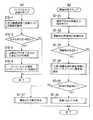
この実施の形態の歯科診療支援の主な動作について図5に示すゼネラルフローに基づいて説明する。 The main operation of dental care support of this embodiment will be described based on the general flow shown in FIG.
まず、認識手段22aにより診療ユニット1の各部の位置認識を行う(装置認識ステップS1)。この詳細フローは図6(a)に示す。 First, the position of each part of the medical unit 1 is recognized by the recognition means 22a (apparatus recognition step S1). This detailed flow is shown in FIG.
次に、認識手段22aにより人物(術者、患者)の認識を行う(人物認識ステップS2)。この詳細フローは図6(b)に示す。 Next, a person (surgeon, patient) is recognized by the recognition means 22a (person recognition step S2). This detailed flow is shown in FIG.
次に、治療ポジションエリアL内の診療ポジションに術者が存在するか、チェアー17上に患者が存在するかを判定し、いずれも存在しない場合、ステップS2の人物認識を続ける。患者が着座し、術者が治療ポジションエリアLの診療ポジションに着いたとき診療開始と判断し、次に進む(診療開始判定ステップS3)。 Next, it is determined whether there is an operator at the medical position in the treatment position area L or there is a patient on the
次に、歯科診療ユニットの各部を術者の診療ポジションに合わせた最適ポジションに移動させる。すなわち、ポジション制御手段22eにより、最適ポジション情報23dから術者個人毎に登録されている各装置の最適ポジションを検索して読み出し、その配置に移動させる(ポジション制御ステップS4)。 Next, each part of the dental practice unit is moved to the optimum position according to the doctor's practice position. That is, the position control means 22e retrieves and reads out the optimum position of each device registered for each individual operator from the
このとき、歯科診療ユニットの各部の制御は、外部接続ポート21に接続された診療ユニット動作制御装置30に対して動作指令信号を送出することによって行う。動作制御の方式については公知の技術を使用することができるが、移動対象、移動先座標、移動経路を指令する。 At this time, each part of the dental care unit is controlled by sending an operation command signal to the diagnosis unit operation control device 30 connected to the
診療ユニット動作制御装置30は図1に示すように、診療チェアー昇降・背板傾動動作部31、テーブル移動動作部32、インスツルメント制御動作部33、アシスタントハンガー移動動作部34、無影灯移動動作部35の各駆動部(たとえばステッピングモータ)に対して動作指令信号を送る。 As shown in FIG. 1, the medical unit operation control device 30 includes a medical chair lifting / lowering plate tilting
次に、ポジション制御ステップS4で動作を開始した歯科診療ユニットの各部の動作を認識する(動作認識ステップS5)。この詳細フローについては図7(a)に示す。 Next, the operation of each part of the dental treatment unit that started the operation in the position control step S4 is recognized (operation recognition step S5). This detailed flow is shown in FIG.
移動した装置各部が、ポジション制御ステップS4で検索した術者の診療ポジションに合わせた最適ポジションに移動したか、すなわち最適停止位置かを判断し、最適停止位置まで移動していれば、動作の終了工程(S9)に進む。最適停止位置に達していなければ次に進む(動作終了判定ステップS6)。 It is determined whether each moved device has moved to the optimum position corresponding to the surgeon's medical position searched in the position control step S4, that is, the optimum stop position. If it has moved to the optimum stop position, the operation ends. Proceed to step (S9). If the optimum stop position has not been reached, the operation proceeds to the next (operation end determination step S6).
移動未了の場合、動作中の歯科診療ユニット各部と、他の部位または人物との接触の恐れがあるか位置関係を監視する(接触監視ステップS7)。この詳細フローについては図7(b)に示す。 If the movement has not been completed, the positional relationship is monitored to determine whether there is a risk of contact between each part of the operating dental care unit and another part or person (contact monitoring step S7). This detailed flow is shown in FIG.
移動により何かと接触することが予測されると判断したときは動作の終了工程(S9)に移行する。接触の恐れがないと判断したときは、移動動作を継続させて動作認識ステップS5に戻る。このフローでは接触することが予測されると判断したとき動作を停止するケースを示したが、障害物を回避するように各装置の移動軌道を変更するためポジション制御ステップS4に戻っても良く、或いは障害となる人物に警告する警報音を鳴らすことの良く、これらを組み合わせても良い(接触判定ステップS8)。 When it is determined that contact with something is predicted due to the movement, the process proceeds to an operation end step (S9). When it is determined that there is no fear of contact, the moving operation is continued and the process returns to the operation recognition step S5. In this flow, the case where the operation is stopped when it is determined that the contact is predicted is shown, but it is possible to return to the position control step S4 in order to change the movement trajectory of each device so as to avoid the obstacle, Or it is good to sound the warning sound which warns the person who becomes an obstacle, and you may combine these (contact determination step S8).
以上により、患者の導入と、術者の診療開始に合わせて診療ユニットのセットが自動的になされて、診療行為が開始され、ステップS10以下のステップに移行する。 As described above, the medical unit is automatically set in accordance with the introduction of the patient and the start of medical treatment by the surgeon, the medical practice is started, and the process proceeds to steps after step S10.
診療中は、インスツルメント判別手段22dにより、治療エリア内の術者の手元を認識し、使用中のインスツルメントを識別し、そのホース制御を行ったり、使用禁止器具のロック制御を行って術者の操作を支援する(インスツルメント認識ステップS10)。この詳細なフローは図8(a)に示す。 During medical treatment, the
続いて、認識手段22aにより人物(術者、患者)の認識を行う(人物認識ステップS11)。この詳細フローはステップ2と同様であり、図6(b)に示す。 Subsequently, a person (surgeon, patient) is recognized by the recognition means 22a (person recognition step S11). This detailed flow is the same as in step 2, and is shown in FIG.
診療の終了を判断するため、診療ポジション或いは治療ポジションエリアLから術者が離れたかを判定する。術者が診療ポジションに存在する場合、診療継続中と判断しステップ10へ戻り監視を継続する。術者が離れた場合、ステップS13へ進む(診療終了判定ステップS12)。 In order to determine the end of the medical care, it is determined whether the operator has left the medical care position or treatment position area L. If the surgeon is present at the medical position, it is determined that the medical service is continuing, and the process returns to step 10 to continue monitoring. When the operator leaves, the process proceeds to step S13 (medical treatment end determination step S12).
診療終了と判断されたとき、歯科診療ユニットの各部をリセット位置に移動させる。この動作では、チェアー17の背板を起こしながらチェアー17を降ろすと共に、患者が退出するときの障害とならないようにテーブルなどを前方に移動させる指令を行う。なお、リセット位置は、前記最適ポジション情報23dに予め座標情報、または画像情報として登録しておき、ポジション制御手段22eが参照して制御信号を診療ユニット動作制御装置30に送出して行われる(ポジション制御ステップS13)。 When it is determined that the medical care is finished, each part of the dental medical unit is moved to the reset position. In this operation, the
次に、ポジション制御ステップ13で動作を開始した歯科診療ユニットの各部の動作を認識する(動作認識ステップS14)。この詳細フローについてはステップ5と同様であり、図7(a)に示す。 Next, the operation of each part of the dental treatment unit that starts the operation in the
続いて、移動した装置各部が、リセット位置に移動したかを判断し、リセット位置まで移動していれば、ステップ18動作の終了工程に飛ぶ。リセット位置に達していなければ次に進む(動作終了判定ステップS15)。 Subsequently, it is determined whether each part of the apparatus that has moved has moved to the reset position, and if it has moved to the reset position, the process jumps to the end step of
移動未了の場合、動作中の診療ユニット各部と、他の部位または人物との接触の恐れがあるか位置関係を監視する(接触監視ステップS16)。この詳細フローについては図7(b)に示す。 If the movement has not been completed, the positional relationship is monitored to determine whether there is a possibility of contact between each part of the operating medical treatment unit and another part or person (contact monitoring step S16). This detailed flow is shown in FIG.
移動により何かと接触することが予測されると判断したときは、ステップS18の動作の終了工程に移行する。接触の恐れがないと判断したときは移動動作を継続させステップS14の動作認識ステップに戻る(接触判定ステップS17)そして、診療ユニットをリセット状態として動作を終了する(ステップS18)。 When it is determined that contact with something is predicted due to the movement, the process proceeds to an operation end step in step S18. When it is determined that there is no risk of contact, the moving operation is continued and the process returns to the operation recognition step of step S14 (contact determination step S17). Then, the medical unit is reset and the operation is terminated (step S18).
以上が主な診療支援動作のフローである。続いて説明した各ステップについての詳細な動作を図6、図7、図8に基づき説明する。 The above is the flow of the main medical assistance operation. Next, the detailed operation of each step described will be described with reference to FIG. 6, FIG. 7, and FIG.
図6(a)は、画像認識による歯科診療支援動作における装置認識ステップ、(b)は人物認識ステップ、(c)は差分画像処理ステップのフローチャートである。 FIG. 6A is a device recognition step in a dental care support operation by image recognition, FIG. 6B is a flowchart of a person recognition step, and FIG. 6C is a flowchart of a difference image processing step.
図6(a)に示す装置認識ステップは、装置各部の位置の確認を行うものであり、まずチェアー背板角度を認識する(チェアー背板角度認識S1−1)。この認識は、取得した画像からチェアー背板部を判別し、予めユニット可動範囲画像情報23aに登録してあるモデルパターンとを比較(パターンマッチング)し、最もマッチング値の高いモデルパターンとの組み合わせを選択する手法により傾き角度を識別する。 In the apparatus recognition step shown in FIG. 6A, the position of each part of the apparatus is confirmed. First, the chair backboard angle is recognized (chair backboard angle recognition S1-1). In this recognition, the chair back board is discriminated from the acquired image, compared with the model pattern registered in the unit movable
次に、取得した画像からテーブルを判別し、予めユニット可動範囲画像情報23aに登録してあるモデルパターンとを比較(パターンマッチング)して、最もマッチング値の高いモデルパターンとの組み合わせを選択してテーブルの位置を求める(テーブル位置認識ステップS1−2)。 Next, the table is discriminated from the acquired image, compared with the model pattern registered in the unit movable
続いて、取得した画像からアシスタントハンガーを判別し、同様にパターンマッチングでアシスタントハンガーの位置を求める(アシスタントハンガー位置認識ステップS1−3)。 Subsequently, the assistant hanger is discriminated from the acquired image, and the position of the assistant hanger is similarly obtained by pattern matching (assistant hanger position recognition step S1-3).
図6(b)に示す人物認識ステップでは、まず、診療エリア(歯科診療ユニット及びチェアー装置周辺)の画像を一定時間間隔で取得し、前後画像を比較してユニット周辺の背景を監視し、動的な変化を抽出する(差分画像処理ステップS2−1)。なお、この差分画像処理ステップの詳細は図6(c)で詳しく説明する。 In the person recognition step shown in FIG. 6B, first, images of a medical area (a dental medical unit and a chair device area) are acquired at regular time intervals, and the background around the unit is monitored by comparing the front and rear images. Change is extracted (difference image processing step S2-1). Details of this difference image processing step will be described in detail with reference to FIG.
続いて、診療エリアの画像内に大きな変化があるかを判定する。大きな変化がなければ、人物認識ステップを終了する。大きな変化があれば次に進む(変化判定ステップS2−2)。 Subsequently, it is determined whether there is a large change in the image of the medical care area. If there is no significant change, the person recognition step is terminated. If there is a large change, the process proceeds to the next (change determination step S2-2).
次に、診療エリアK(ユニット周辺)の中で差分の大きなエリアを特定する(変化エリア特定ステップS2−3)。 Next, an area with a large difference is specified in the medical area K (around the unit) (change area specifying step S2-3).
続いて、変化エリアが患者が着座するチェアー周辺であるか否かを判別し、チェアー周辺であればステップS2−5に進む(患者判断ステップS2−4)。 Subsequently, it is determined whether or not the change area is around the chair where the patient is seated. If the change area is around the chair, the process proceeds to step S2-5 (patient determination step S2-4).
変化エリアが術者が着座する治療ポジションエリアLの周辺(診療ポジション)か否かを判別し、治療ポジションエリアL周辺であればステップS2−7に進む(術者判断ステップS2−6)。 It is determined whether or not the change area is around the treatment position area L where the operator is seated (medical position). If the change area is around the treatment position area L, the process proceeds to step S2-7 (operator judgment step S2-6).
患者の存在を確認し、患者顔画像を取得して、患者画像情報23cとパターンマッチングすることにより患者個人の識別を行う(患者着座判定S2−5)。表示手段22fは、この患者個人識別により、患者のID番号から歯科診療サーバ50に格納されている患者情報を検索して、表示装置11に表示する。 The presence of the patient is confirmed, a patient face image is acquired, and the patient is identified by pattern matching with the
治療ポジションエリアLに術者の存在が認識されたとき、術者の診療ポジションの位置を判定し、また、術者の顔画像を取得して、術者画像情報23bとパターンマッチングすることにより術者個人を識別する(術者診療ポジション判定ステップS2−7)。 When the presence of the surgeon is recognized in the treatment position area L, the position of the surgeon's medical position is determined, and a face image of the surgeon is acquired and subjected to pattern matching with the
この術者個人識別により、ポジション制御手段22eは術者ごとの最適な装置各部の配置を最適ポジション情報23dから検索し、術者個人の診療スタイルに合わせた装置の移動を指令することが可能となる。 By this individual identification of the operator, the position control means 22e can search for the optimal arrangement of each part of the apparatus for each operator from the
ステップS2−1における差分画像処理ステップの詳細を図6(c)により説明する。まず、カメラから画像Aを取得する(ステップS2−11)。続いて、所定の変化監視間隔をタイマーにセットする(ステップS2−12)。 Details of the difference image processing step in step S2-1 will be described with reference to FIG. First, the image A is acquired from the camera (step S2-11). Subsequently, a predetermined change monitoring interval is set in the timer (step S2-12).
タイマーセット時間の経過を監視し、セット時間に達したとき次に進む(ステップS2−13)。 The progress of the timer set time is monitored, and when the set time is reached, the process proceeds to the next (step S2-13).
次に、カメラから画像Bを取得し(ステップS2−14)、取得した画像Aと画像Bとを比較し差分画像を取得する(ステップS2−15)。 Next, the image B is acquired from the camera (step S2-14), and the acquired image A and the image B are compared to acquire a difference image (step S2-15).
図7(a)は、画像認識による歯科診療支援動作における動作認識ステップ、(b)は接触監視ステップのフローチャートである。 FIG. 7A is an operation recognition step in a dental care support operation by image recognition, and FIG. 7B is a flowchart of a contact monitoring step.
図7(a)は、図6で説明したステップS5及びS14の動作認識ステップの詳細を示している。まず、上述した差分画像処理ステップ(図6(c))で得られた差分画像のエリアから、チェアー17が動作中か判断する。変化がない場合には、ステップS5−4に移る(ステップS5−1)。 FIG. 7A shows details of the operation recognition step in steps S5 and S14 described in FIG. First, it is determined whether the
チェアー17に変化が認められたときは、動作前画像と動作後画像とにより画像中の位置と動作方向を推定する(ステップS5−2)。続いて、パターンマッチングによりチェアー背板の角度を認識する(ステップS5−3)。 When a change is recognized in the
次に、差分画像のエリアから、テーブル13が動作中か判断する。変化がない場合、ステップS5−7に移る(ステップS5−4)。テーブル13に変化が認められたときは、動作前画像と動作後画像により画像中の位置と動作方向を推定する(ステップS5−5)。続いて、パターンマッチングによりテーブル位置を認識する(ステップS5−6)。 Next, it is determined from the difference image area whether the table 13 is operating. If there is no change, the process proceeds to step S5-7 (step S5-4). When a change is recognized in the table 13, the position and the motion direction in the image are estimated from the pre-motion image and the post-motion image (step S5-5). Subsequently, the table position is recognized by pattern matching (step S5-6).
次に、差分画像のエリアから、アシスタントハンガー14が動作中か判断し、変化がない場合は終了する(ステップS5−7)。アシスタントハンガー14に変化が認められたとき、動作前画像と動作後画像により画像中の位置と動作方向を推定する(ステップS5−8)。続いて、パターンマッチングによりアシスタントハンガー14位置を認識する(ステップS5−9)。 Next, it is determined from the area of the difference image whether the
図7(b)は、図6で説明した接触監視ステップS7の詳細を示すフローチャートである。まず、差分画像処理ステップ(図6(c))で得られた差分画像のエリアから、チェアー17が動作中か判断する。変化がない場合、ステップS7−3に移る(ステップS7−1)。 FIG. 7B is a flowchart showing details of the contact monitoring step S7 described in FIG. First, it is determined whether the
チェアー17に変化が認められたとき、その位置と動作方向から、移動先の推定を行い、移動先に障害物に接触する恐れがあるか判定する(ステップS7−2)。なお、この接触判定ステップ(ステップS7−2)の詳細は図8(b)に示し、説明を後述する。 When a change is recognized in the
続いて、テーブル13が動作中か判断し、変化がない場合は、ステップS7−5に移る(ステップS7−3)。テーブル13に変化が認められたとき、その位置と動作方向から、移動先の推定を行い、移動先に障害物に接触する恐れがあるか判定する(ステップS7−4)。 Subsequently, it is determined whether the table 13 is operating. If there is no change, the process proceeds to step S7-5 (step S7-3). When a change is recognized in the table 13, the movement destination is estimated from the position and the movement direction, and it is determined whether or not there is a possibility that the movement destination touches an obstacle (step S7-4).
続いて、アシスタントハンガー14が動作中か判断し、変化がない場合は、終了する(ステップS7−5)。アシスタントハンガー14に変化が認められたときは、その位置と動作方向から、移動先の推定を行い、移動先に障害物に接触する恐れがあるか判定する(ステップS7−6)。 Subsequently, it is determined whether the
図8(a)は、画像認識による歯科診療支援動作におけるインスツルメント認識ステップ、(b)は接触判定ステップのフローチャートである。 FIG. 8A is an instrument recognition step in the dental care support operation by image recognition, and FIG. 8B is a flowchart of the contact determination step.
図8(a)は、図5におけるステップS10の詳細を示す。まず、上述した差分画像処理ステップで得られた治療エリアN周辺の差分画像を監視する(ステップS10−1)。このとき、治療エリアN周辺だけをデジタルズーム機能により取り込むか、光学ズーム機能を備えたカメラを用いてクローズアップ画像を用いることにより、認識精度を確保することができる。図3に示した無影灯12に取り付けたカメラ10の場合、カメラ位置をC位置とすれば、治療エリアNの真上で、かつ被写体までの距離が近いため認識精度を高めることが可能となる。 FIG. 8A shows details of step S10 in FIG. First, the difference image around the treatment area N obtained in the difference image processing step described above is monitored (step S10-1). At this time, recognition accuracy can be ensured by capturing only the periphery of the treatment area N with the digital zoom function or using a close-up image using a camera having an optical zoom function. In the case of the
治療エリアN周辺及び治療エリアN内の画像に大きな変化がなければ終了する。大きな変化が認められた場合には、ステップS10−3に移る(ステップS10−2)。 If there is no significant change in the image around the treatment area N and within the treatment area N, the process is terminated. When a big change is recognized, it moves to step S10-3 (step S10-2).
治療エリアN周辺及び治療エリアN内の中で差分(変化)の大きなエリアを特定すると共に、術者の手、把持している器具の動作方向を認識する(ステップS10−3)。このとき、治療エリアを分割したエリアとして特定することにより、処理を効率よく行うことができる。 An area with a large difference (change) is specified around the treatment area N and within the treatment area N, and the operating direction of the operator's hand and the grasped instrument is recognized (step S10-3). At this time, the treatment can be efficiently performed by specifying the treatment area as the divided area.
続いて、治療エリアN内で使用されているインスツルメントをパターンマッチング・色識別によって特定する(ステップS10−4)。このインスツルメント識別によって、インスツルメントロック手段22gは、重複して使用することが禁止されているインスツルメントが同時に識別された際に、インスツルメント制御動作部33に制御信号を出してインターロックしたり、識別されたインスツルメント以外をインターロックすることができる。 Subsequently, the instrument used in the treatment area N is specified by pattern matching and color identification (step S10-4). By this instrument identification, the instrument lock means 22g outputs a control signal to the instrument
さらに、インスツルメントホース制御手段22hが、インスツルメントを把持している術者の手の位置と動きを追尾判断する。そして、使用インスツルメントが診療エリアN内に移動されたときにはインスツルメントホース16aを送り出し状態とし、治療エリアN内にあるときはテンションフリー状態とし、使用インスツルメントが治療エリアN外に移動されたときはインスツルメントホース16aを巻き取り状態とする。 Further, the instrument hose control means 22h makes a tracking determination on the position and movement of the operator's hand holding the instrument. When the instrument used is moved into the medical area N, the
これらのインスツルメントならびに術者の手を識別する際に、インスツルメントのグリップやホースを色分けし、術者の手袋に決まった色を使用することが好ましい。このようにすることにより、インスツルメントの握り方や向きの変化があっても、さらに識別効果を高めることができる。 When identifying these instruments and the hand of the surgeon, it is preferable to color-code the grips and hoses of the instrument and use a predetermined color for the surgeon's gloves. By doing in this way, even if there is a change in the way the instrument is gripped or the direction, the discrimination effect can be further enhanced.
また、歯科診療管理サーバ50からの診療情報が取得されている場合、次の診療工程で必要となるインスツルメントの準備動作を自動的に行うことも可能である。従って、例えば、診療開始直後に使用する器具を取り出しやすい状態にしておくことができる。さらに、患者に説明のため治療説明を行うために使用する口腔内カメラを、取り出しやすいようにインスツルメントハンガーからせり出させたりすることができる。 In addition, when medical information is acquired from the dental
図8(b)は、図7(b)における接触判定ステップS7−2の詳細フローチャートである。まず差分画像処理で得られた情報から、目的の装置の動作方向を把握して移動先の推定を行う(ステップS7−21)。次に、移動先の障害物の有無を判定する(ステップS7−22)。このとき、第1のカメラ10aからの平面位置情報と第3のカメラ10cからの水平視した位置情報の両方を用いて高さについても判断する。 FIG. 8B is a detailed flowchart of the contact determination step S7-2 in FIG. First, from the information obtained by the differential image processing, the movement direction of the target device is grasped and the movement destination is estimated (step S7-21). Next, the presence / absence of an obstacle at the destination is determined (step S7-22). At this time, the height is also determined using both the planar position information from the
障害物との距離は、移動している装置の外周から100mm〜200mm離れた周囲、または、術者の体型の外周から100mm〜200mm離れた範囲を境界エリアとし、この境界エリア近傍の障害物の有無を判定することが望ましい。障害物が認識されなければ終了し、障害物があればステップS7−24に進む(ステップS7−23)。 The distance to the obstacle is a boundary area that is 100 mm to 200 mm away from the outer periphery of the moving apparatus, or a range that is 100 mm to 200 mm away from the outer circumference of the operator's body shape. It is desirable to determine the presence or absence. If no obstacle is recognized, the process ends. If there is an obstacle, the process proceeds to step S7-24 (step S7-23).
ステップS7−24では、人物・装置各部の画像情報とパターンマッチングして障害物を識別する。そして、識別された障害物が既知の障害物(テーブル、アシスタントハンガー、規定ポジションの術者)の場合、第3のカメラ10cの画像から高さ方向を考慮した接触(当たり)予測を行う(ステップS7−26)。 In step S7-24, the obstacle is identified by pattern matching with the image information of each part of the person / device. Then, when the identified obstacle is a known obstacle (table, assistant hanger, surgeon at the specified position), contact (hit) prediction is performed in consideration of the height direction from the image of the
接触(当たり)予測では、チェアー背板の傾動に際してドクターチェアー19に座っている術者の足が、背板にぶつかる危険があることを察知して警告したり、停止させたりすることが可能となる。これにより、背板によるドクターの脚挟みこみなどの事故を防止することができる。これに対し、障害物が既知のものでない場合(たとえば、患者が動き出したときなど)は、警告または動作停止させる(ステップS7−27)。 According to the contact (hit) prediction, it is possible to warn or stop the operator's foot sitting on the
本発明は以上の実施の形態に限定されることなく、種々変形が可能である。本発明では、術者がテーブルなど各装置を微調整のために手動で移動させても、その位置を認識することが可能であり、さらに診療中に、術者が診療ポジションを変えた場合でもリアルタイムにその位置を把握認識することができることから、それらの動きに合わせて最適ポジションに各装置を再配置するように制御することも可能となる。また、従来の動作制御においては、位置検出用センサーや、ステッピングモータによる制御が必要であったが、本発明によれば、画像認識で位置を検出するため複雑な制御配線やプログラムを必要としないものである。 The present invention is not limited to the above embodiment, and various modifications can be made. In the present invention, it is possible to recognize the position even if the operator manually moves each device such as a table for fine adjustment, and even if the operator changes the medical position during medical treatment. Since the position can be grasped and recognized in real time, it is possible to perform control so that each device is rearranged to the optimum position in accordance with the movement thereof. Further, in the conventional operation control, control by a position detection sensor or a stepping motor is necessary. However, according to the present invention, a complicated control wiring or program is not required for detecting a position by image recognition. Is.
1 歯科診療ユニット
10 カメラ
10a 第1のカメラ
10b 第2のカメラ
10c 第3のカメラ
11 表示装置
12 無影灯
12a,12b,12c,12d,12e 支持アーム
13 テーブル
13a,13b,13c 支持アーム
14 アシスタントハンガー
15 インスツルメントハンガー
16 インスツルメント
16a インスツルメントホース
17 チェアー
18 フットペダル
20 画像認識・制御コンピュータ
21 外部接続ポート
23 記憶部
30 診療ユニット動作制御装置
31 診療チェア昇降・背板傾動動作部
32 テーブル移動動作部
33 インスツルメント制御動作部
34 アシスタントハンガー移動動作部
35 無影灯移動動作部DESCRIPTION OF SYMBOLS 1
Claims (2)
Translated fromJapaneseカメラからの画像情報に基づいて歯科診療ユニットにおける各装置の位置及び患者、術者の存在並びにその位置をリアルタイムに認識する認識手段と、
術者の顔画像を記録した術者画像情報と、
前記認識手段が術者の存在を認識したとき、前記カメラからの術者の顔画像と前記術者画像情報の顔画像とをパターンマッチングして術者識別を行う術者識別手段と、
術者識別手段が識別した術者の診療スタイルに合わせた最適な位置に歯科診療ユニットにおける所定の装置を移動させるポジション制御手段とを備え、
前記認識手段は前記カメラからの画像を一定時間間隔で取得し、前後画像を比較して歯科診療ユニット周辺の背景を監視し、その差分画像から動的な変化を抽出し、前記動的な変化が術者が着座する治療ポジションエリアの周辺か否かを判別し、
前記認識手段が治療ポジションエリア周辺と判別したとき、前記術者識別手段が前記術者識別を行うことを特徴とする画像認識による歯科診療支援システム。A dental care unit including a medical chair on which a patient is seated, and one or more cameras for obtaining image information of a medical area in the vicinity of the examination chair of the surgeon and assistant;
Recognizing means for recognizing in real time the position of each device in the dental care unit and the presence of the patient and the operator and its position based on image information from the camera;
The surgeon image information that records the surgeon's face image,
When the recognizing means recognizes the presence of an operator, an operator identifying means for performing an operator identification by pattern matching the face image of the operator from the camera and the face image of the operator image information;
A position control means for moving a predetermined device in the dental care unit to an optimal position according to the treatment style of the surgeon identified by the surgeon identification means,
The recognition means obtains images from the camera at regular time intervals, compares the front and back images, monitors the background around the dental care unit, extracts dynamic changes from the difference image, and extracts the dynamic changes. To determine if it is around the treatment position area where the surgeon is seated,
A dental care support system based on image recognition, wherein the surgeon identification means performs the surgeon identification when the recognition means discriminates around the treatment position area.
カメラからの画像情報に基づいて歯科診療ユニットにおける各装置の位置及び患者、術者の存在並びにその位置をリアルタイムに認識する認識手段と、
術者の顔画像を記録した術者画像情報と、
患者の顔画像を記録した患者画像情報と、
前記認識手段が術者の存在を認識したとき、前記カメラからの術者の顔画像と前記術者画像情報の顔画像とをパターンマッチングして術者識別を行う術者識別手段と、
前記認識手段が患者の存在を認識したとき、前記カメラからの患者の顔画像と前記患者画像情報の顔画像とをパターンマッチングして患者識別を行う患者識別手段と、
術者識別手段が識別した術者の診療スタイルに合わせた最適な位置に歯科診療ユニットにおける所定の装置を移動させるポジション制御手段とを備え、
前記認識手段は前記カメラからの画像を一定時間間隔で取得し、前後画像を比較して歯科診療ユニット周辺の背景を監視し、その差分画像から動的な変化を抽出し、前記動的な変化が術者が着座する治療ポジションエリアの周辺か否か及び患者が着座するチェアー周辺か否かを判別し、
前記認識手段が治療ポジションエリア周辺と判別したとき、前記術者識別手段が前記術者識別を行い、前記認識手段が患者が着座するチェアー周辺と判別したとき、前記患者識別手段が前記患者識別を行うことを特徴とする画像認識による歯科診療支援システム。A dental care unit including a medical chair on which a patient is seated, and one or more cameras for obtaining image information of a medical area in the vicinity of the examination chair of the surgeon and assistant;
Recognizing means for recognizing in real time the position of each device in the dental care unit and the presence of the patient and the operator and its position based on image information from the camera;
The surgeon image information that records the surgeon's face image,
Patient image information that records the patient's face image, and
When the recognizing means recognizes the presence of an operator, an operator identifying means for performing an operator identification by pattern matching the face image of the operator from the camera and the face image of the operator image information;
When the recognition means recognizes the presence of a patient, patient identification means for performing patient identification by pattern matching the patient's face image from the camera and the face image of the patient image information;
A position control means for moving a predetermined device in the dental care unit to an optimal position according to the treatment style of the surgeon identified by the surgeon identification means,
The recognition means obtains images from the camera at regular time intervals, compares the front and back images, monitors the background around the dental care unit, extracts dynamic changes from the difference image, and extracts the dynamic changes. To determine whether it is around the treatment position area where the operator is seated and whether it is around the chair where the patient is seated,
When the recognizing means discriminates around the treatment position area, the operator identifying means performs the operator identification, and when the recognizing means discriminates around the chair where the patient is seated, the patient identifying means performs the patient identification. A dental care support system based on image recognition.
Priority Applications (1)
| Application Number | Priority Date | Filing Date | Title |
|---|---|---|---|
| JP2008144017AJP4653822B2 (en) | 2008-06-02 | 2008-06-02 | Dental care support system based on image recognition |
Applications Claiming Priority (1)
| Application Number | Priority Date | Filing Date | Title |
|---|---|---|---|
| JP2008144017AJP4653822B2 (en) | 2008-06-02 | 2008-06-02 | Dental care support system based on image recognition |
Related Parent Applications (1)
| Application Number | Title | Priority Date | Filing Date |
|---|---|---|---|
| JP2002330860ADivisionJP4172689B2 (en) | 2002-11-14 | 2002-11-14 | Dental care support system based on image recognition |
Publications (2)
| Publication Number | Publication Date |
|---|---|
| JP2008200539A JP2008200539A (en) | 2008-09-04 |
| JP4653822B2true JP4653822B2 (en) | 2011-03-16 |
Family
ID=39778573
Family Applications (1)
| Application Number | Title | Priority Date | Filing Date |
|---|---|---|---|
| JP2008144017AExpired - Fee RelatedJP4653822B2 (en) | 2008-06-02 | 2008-06-02 | Dental care support system based on image recognition |
Country Status (1)
| Country | Link |
|---|---|
| JP (1) | JP4653822B2 (en) |
Families Citing this family (7)
| Publication number | Priority date | Publication date | Assignee | Title |
|---|---|---|---|---|
| JP2011036589A (en)* | 2009-08-18 | 2011-02-24 | Gc Corp | Dental unit |
| JP5634735B2 (en)* | 2010-04-14 | 2014-12-03 | 株式会社モリタ製作所 | Medical lighting device and medical diagnostic device |
| JP5647046B2 (en)* | 2011-03-18 | 2014-12-24 | 株式会社モリタ製作所 | Medical treatment equipment |
| JP5650568B2 (en)* | 2011-03-18 | 2015-01-07 | 株式会社モリタ製作所 | Medical treatment equipment |
| JP2012203572A (en)* | 2011-03-24 | 2012-10-22 | Morita Mfg Co Ltd | Medical treatment device |
| JP5884119B2 (en)* | 2011-07-14 | 2016-03-15 | 学校法人 日本歯科大学 | Medical training system |
| KR102531166B1 (en)* | 2020-12-02 | 2023-05-11 | 오스템임플란트 주식회사 | A dental diagnostic device, its operation method and a computer-readable recording medium in which a program for executing the same is recorded |
Family Cites Families (9)
| Publication number | Priority date | Publication date | Assignee | Title |
|---|---|---|---|---|
| JPH0248259B2 (en)* | 1987-07-08 | 1990-10-24 | Yoshida Seisakusho Kk | CHIRYOSOCHI |
| JP3086960B2 (en)* | 1990-11-22 | 2000-09-11 | 株式会社モリタ東京製作所 | Dental unit |
| JPH05268599A (en)* | 1992-03-17 | 1993-10-15 | Fujitsu Ltd | Automatic control method of human image pickup camera in video conference system |
| JP3194706B2 (en)* | 1997-01-30 | 2001-08-06 | タカラベルモント株式会社 | Dental care equipment |
| JPH11183145A (en)* | 1997-10-15 | 1999-07-09 | Yuusuke Nonomura | Three-dimensional observation apparatus |
| US6513015B2 (en)* | 1998-09-25 | 2003-01-28 | Fujitsu Limited | System and method for customer recognition using wireless identification and visual data transmission |
| JP3750782B2 (en)* | 1998-12-01 | 2006-03-01 | 株式会社モリタ製作所 | Dental care equipment |
| JP3860682B2 (en)* | 1999-05-14 | 2006-12-20 | 株式会社モリタ製作所 | Medical treatment equipment |
| JP3897962B2 (en)* | 2000-07-19 | 2007-03-28 | 株式会社モリタ製作所 | Identification-type instrument body, identification-type adapter, identification-type tube, and medical device using these |
- 2008
- 2008-06-02JPJP2008144017Apatent/JP4653822B2/ennot_activeExpired - Fee Related
Also Published As
| Publication number | Publication date |
|---|---|
| JP2008200539A (en) | 2008-09-04 |
Similar Documents
| Publication | Publication Date | Title |
|---|---|---|
| JP4172689B2 (en) | Dental care support system based on image recognition | |
| JP4653822B2 (en) | Dental care support system based on image recognition | |
| US11297285B2 (en) | Dental and medical loupe system for lighting control, streaming, and augmented reality assisted procedures | |
| CN106102633B (en) | Structural adjustment system and method for teleoperating medical systems | |
| US6361323B1 (en) | Skill acquisition, transfer and verification system hardware and point tracking system applied to health care procedures | |
| US20190310819A1 (en) | Augmented reality image display systems and methods | |
| WO2020062773A1 (en) | Tms positioning navigation method used for transcranial magnetic stimulation treatment | |
| JP2007007041A (en) | Surgery support | |
| KR20140148243A (en) | Method for providing information and medical diagnosis apparatus thereto | |
| JP5315524B2 (en) | Medical diagnostic imaging equipment | |
| JPH0670884A (en) | Medical diagnostic device using sight line detection | |
| JP5647045B2 (en) | Medical treatment equipment | |
| JP5650568B2 (en) | Medical treatment equipment | |
| JP5647046B2 (en) | Medical treatment equipment | |
| JP2001275931A (en) | Medical treatment system | |
| JP6806364B2 (en) | Dental treatment unit | |
| JP2023107913A (en) | Ophthalmologic apparatus and ophthalmologic system | |
| CN118304165B (en) | Intelligent robot for moxibustion and thermal therapy based on infrared-visible light fusion positioning and its control method | |
| JP3942965B2 (en) | Ophthalmic equipment system | |
| CN110638524B (en) | A real-time simulation system for tumor puncture based on VR glasses | |
| KR101683176B1 (en) | Method for providing information and magnetic resonance imaging apparatus thereto | |
| JP4102155B2 (en) | Surgical light automatic position correction lighting system | |
| CN117190138A (en) | Medical lighting devices, operating tables, treatment chairs, and lighting controllers, methods and devices | |
| JP5647049B2 (en) | Medical treatment equipment | |
| JP2021509298A (en) | Systems and methods for retrieving data associated with damage |
Legal Events
| Date | Code | Title | Description |
|---|---|---|---|
| A521 | Request for written amendment filed | Free format text:JAPANESE INTERMEDIATE CODE: A523 Effective date:20080701 | |
| A621 | Written request for application examination | Free format text:JAPANESE INTERMEDIATE CODE: A621 Effective date:20080701 | |
| TRDD | Decision of grant or rejection written | ||
| A01 | Written decision to grant a patent or to grant a registration (utility model) | Free format text:JAPANESE INTERMEDIATE CODE: A01 Effective date:20101201 | |
| A01 | Written decision to grant a patent or to grant a registration (utility model) | Free format text:JAPANESE INTERMEDIATE CODE: A01 | |
| A61 | First payment of annual fees (during grant procedure) | Free format text:JAPANESE INTERMEDIATE CODE: A61 Effective date:20101217 | |
| R150 | Certificate of patent or registration of utility model | Ref document number:4653822 Country of ref document:JP Free format text:JAPANESE INTERMEDIATE CODE: R150 Free format text:JAPANESE INTERMEDIATE CODE: R150 | |
| FPAY | Renewal fee payment (event date is renewal date of database) | Free format text:PAYMENT UNTIL: 20131224 Year of fee payment:3 | |
| R250 | Receipt of annual fees | Free format text:JAPANESE INTERMEDIATE CODE: R250 | |
| R250 | Receipt of annual fees | Free format text:JAPANESE INTERMEDIATE CODE: R250 | |
| R250 | Receipt of annual fees | Free format text:JAPANESE INTERMEDIATE CODE: R250 | |
| R250 | Receipt of annual fees | Free format text:JAPANESE INTERMEDIATE CODE: R250 | |
| R250 | Receipt of annual fees | Free format text:JAPANESE INTERMEDIATE CODE: R250 | |
| R250 | Receipt of annual fees | Free format text:JAPANESE INTERMEDIATE CODE: R250 | |
| R250 | Receipt of annual fees | Free format text:JAPANESE INTERMEDIATE CODE: R250 | |
| R250 | Receipt of annual fees | Free format text:JAPANESE INTERMEDIATE CODE: R250 | |
| LAPS | Cancellation because of no payment of annual fees |