JP4651120B2 - Vehicle lighting - Google Patents
Vehicle lightingDownload PDFInfo
- Publication number
- JP4651120B2 JP4651120B2JP2007083304AJP2007083304AJP4651120B2JP 4651120 B2JP4651120 B2JP 4651120B2JP 2007083304 AJP2007083304 AJP 2007083304AJP 2007083304 AJP2007083304 AJP 2007083304AJP 4651120 B2JP4651120 B2JP 4651120B2
- Authority
- JP
- Japan
- Prior art keywords
- light
- lens cut
- light source
- optical axis
- main optical
- Prior art date
- Legal status (The legal status is an assumption and is not a legal conclusion. Google has not performed a legal analysis and makes no representation as to the accuracy of the status listed.)
- Expired - Fee Related
Links
Images


Landscapes
- Non-Portable Lighting Devices Or Systems Thereof (AREA)
Description
Translated fromJapanese本発明は、光源の主光軸線と所定範囲の放射角をもって光源から放射された光よりも、光源の主光軸線と大きい角度をなして光源から放射された光を大きく集光させるように構成された車両用灯具に関し、特には、全体を小型化しつつ、要求される光度分布に適合させるための設計変更を容易にすることができる車両用灯具に関する。The present invention is configured to concentrate light emitted from the light source at a larger angle with the main optical axis of the light source than the light emitted from the light source with the main optical axis of the light source and a predetermined range of emission angles. It relates toa vehicle lamp which is, inparticular, while downsizing the whole, relates toa vehicular lamp that can facilitate design changes to adapt to the required intensity distribution.
従来から、光源(例えば発光ダイオード)の主光軸線(光軸)と小さい角度をなして光源から放射された光よりも、主光軸線と大きい角度をなして光源から放射された光を大きく集光させるように構成された車両用灯具が知られている。この種の車両用灯具の例としては、例えば特許文献1に記載されたものがある。 Conventionally, the light emitted from the light source at a large angle with the main optical axis is larger than the light emitted from the light source at a small angle with the main optical axis (optical axis) of the light source (for example, light emitting diode). A vehicular lamp configured to emit light is known. An example of this type of vehicular lamp is described in
特許文献1に記載された車両用灯具では、光源の主光軸線と小さい角度をなして光源から放射された光は、反射されることなく、直射光として照射されている。また、主光軸線と大きい角度をなして放射された光は、光源の外部に設けられたリフレクタ(反射部材)によって主光軸線の側に集光せしめられ、照射されている。
それにより、本車両用灯具では、要求される光度分布(配光分布)が得られている。In the vehicular lamp described in
Thereby, in this vehicle lamp, the required light intensity distribution (light distribution) is obtained.
従って、所望の高度分布を得るために当該車両用灯具では、主光軸線と大きい角度をなして放射された光を主光軸線の側に集光させるために、光源の周囲にリフレクタを配置しなければならない。 Therefore, in order to obtain a desired altitude distribution, the vehicle lamp has a reflector disposed around the light source in order to collect light emitted at a large angle with the main optical axis toward the main optical axis. There must be.
そのため、光源の周囲にリフレクタを配置するためのスペースを確保しなければならず、その結果、車両用灯具全体が大型化してしまう。 Therefore, it is necessary to secure a space for arranging the reflector around the light source, and as a result, the entire vehicular lamp is enlarged.
また、リフレクタを配置するためのスペースを確保しなければならないため、隣接する2つの光源の間隔が広くなってしまう。 In addition, since a space for arranging the reflectors must be secured, the interval between two adjacent light sources becomes wide.
更に、例えば光源の仕様変更などがあった場合には、要求される光度分布(配光分布)が得られるように、光源の周囲の非常に狭いスペースに配置されたリフレクタも設計変更しなければならない。 Furthermore, for example, when there is a change in the specifications of the light source, the reflectors arranged in a very narrow space around the light source must also be redesigned so that the required light intensity distribution (light distribution distribution) can be obtained. Don't be.
次に、本発明の車両用灯具に関連する技術について説明する。 Next, a technique related to the vehicular lamp of the present invention will be described.
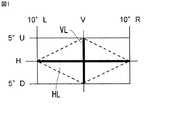
図1は車両用灯具の配光規格を説明するための図である。図1において、「H」は水平線を示しており、「V」は車両用灯具の主光軸線と交差する鉛直線を示している。「5°U」は水平線Hより5°上向きを示しており、「5°D」は水平線Hより5°下向きを示している。「10°R」は車両用灯具の主光軸線方向より10°右向きを示しており、「10°L」は車両用灯具の主光軸線方向より10°左向きを示している。 FIG. 1 is a diagram for explaining a light distribution standard of a vehicular lamp. In FIG. 1, “H” indicates a horizontal line, and “V” indicates a vertical line that intersects the main optical axis of the vehicular lamp. “5 ° U” indicates 5 ° upward from the horizontal line H, and “5 ° D” indicates 5 ° downward from the horizontal line H. “10 ° R” indicates 10 ° rightward from the main optical axis direction of the vehicular lamp, and “10 ° L” indicates 10 ° leftward from the main optical axis direction of the vehicular lamp.
例えばリアフォグランプの配光規格では、図1中の線HV上の光度が150cd以上になり、図1中の線VL上の光度が150cd以上になるように規定されている。また、図1中の破線の内側の部分の光度が75cd以上になり、かつ、300cd以下になるように規定されている。 For example, the rear fog lamp light distribution standard specifies that the luminous intensity on the line HV in FIG. 1 is 150 cd or more and the luminous intensity on the line VL in FIG. 1 is 150 cd or more. Further, the luminous intensity of the portion inside the broken line in FIG. 1 is specified to be 75 cd or more and 300 cd or less.
図2は本発明に関連する車両用灯具の断面図である。図2において、Sは白熱球光源を示しており、CLは光源Sの主光軸線を示している。Rは光源Sからの放射光の一部を反射するためのリフレクタを示しており、LSはレンズを示している。LC1,LC2,LC3,LC4はレンズLSに形成されたレンズカットを示している。 FIG. 2 is a sectional view of a vehicular lamp related to the present invention. In FIG. 2, S indicates an incandescent bulb light source, and CL indicates the main optical axis of the light source S. R indicates a reflector for reflecting a part of the radiated light from the light source S, and LS indicates a lens. LC1, LC2, LC3, and LC4 indicate lens cuts formed on the lens LS.
図2に示すように、光源Sから放射された光A’がレンズカットLC1によって屈折せしめられ、レンズカットLC1を透過した光Aが拡散光となって照射方向(図2の上側)に照射される。また、光源Sから放射された光B’がレンズカットLC2によって屈折せしめられ、レンズカットLC2を透過した光Bが拡散光となって照射方向に照射される。 As shown in FIG. 2, the light A ′ emitted from the light source S is refracted by the lens cut LC1, and the light A that has passed through the lens cut LC1 becomes diffused light and is irradiated in the irradiation direction (upper side in FIG. 2). The Further, the light B ′ radiated from the light source S is refracted by the lens cut LC2, and the light B transmitted through the lens cut LC2 is irradiated in the irradiation direction as diffused light.
更に、図2に示すように、光源Sから放射された光C”が、リフレクタRによって反射され、光源Sの主光軸線CLにほぼ平行な反射光C’になる。次いで、その反射光C’がレンズカットLC3によって屈折せしめられ、レンズカットLC3を透過した光Cが拡散光となって照射方向に照射される。また、光源Sから放射された光D”が、リフレクタRによって反射され、光源Sの主光軸線CLにほぼ平行な反射光D’になる。次いで、その反射光D’がレンズカットLC4によって屈折せしめられ、レンズカットLC4を透過した光Dが拡散光となって照射方向に照射される。 Further, as shown in FIG. 2, the light C ″ emitted from the light source S is reflected by the reflector R to become reflected light C ′ substantially parallel to the main optical axis CL of the light source S. Next, the reflected light C 'Is refracted by the lens cut LC3, and the light C transmitted through the lens cut LC3 is diffused and irradiated in the irradiation direction. The light D "emitted from the light source S is reflected by the reflector R, The reflected light D ′ is substantially parallel to the main optical axis CL of the light source S. Next, the reflected light D 'is refracted by the lens cut LC4, and the light D transmitted through the lens cut LC4 is diffused and irradiated in the irradiation direction.
図3(A)及び図3(B)は図2に示した光Aの光度分布CA、光Bの光度分布CB、光Cの光度分布CCおよび光Dの光度分布CDを説明するための図である。詳細には、図3(A)は光Aの光度分布CA、光Bの光度分布CB、光Cの光度分布CCおよび光Dの光度分布CDのそれぞれを示した図、図3(B)は図3(A)に示した光Aの光度分布CA、光Bの光度分布CB、光Cの光度分布CCおよび光Dの光度分布CDを合成した図である。FIGS.3(A) and. 3(B) diagram for explaining the light intensity distribution CD of luminous intensity distribution CA, luminous intensity distribution CB of the light B, the optical C luminous intensity distribution CC and light D of the light A shown in FIG. 2 It is. In particular,FIG. 3(A) intensity distribution of the light A CA, luminous intensity distribution CB of the light B, fig showing respective luminous intensity distribution CD of luminous intensity distribution CC and light D of the light C,FIG. 3(B) It is the figure which synthesize | combined the luminous intensity distribution CA of the light A, luminous intensity distribution CB of the light B, luminous intensity distribution CC of the light C, and luminous intensity distribution CD of the light D shown to FIG. 3( A) .
図3(A)及び図3(B)において、縦軸は光度を示しており、横軸は、水平に延びている光源Sの主光軸線CL(図2参照)に対する水平方向角度(水平線H(図1参照)上角度)を示している。すなわち、「水平線H上角度0(°)」は、光源Sの主光軸線CL上を示している。In FIG. 3(A) and 3FIG. 3(B), the vertical axis represents the light intensity and the horizontal axis, the horizontal angle (a horizontal line H with respect to the main optical axis CL of the light source S which extends horizontally (see FIG. 2) (See FIG. 1). That is, “angle 0 (°) on the horizontal line H” indicates the main optical axis line CL of the light source S.
この車両用灯具では、フィラメントを有する白熱球が光源Sとして用いられている。そのため、光源Sから放射された光A’,B’,C”,D”の光度がほぼ均一になり、レンズLSを透過した光A,B,C,Dの光度もほぼ均一になる。 In this vehicular lamp, an incandescent bulb having a filament is used as the light source S. Therefore, the light intensity of the light A ′, B ′, C ″, D ″ emitted from the light source S is substantially uniform, and the light intensity of the light A, B, C, D transmitted through the lens LS is also substantially uniform.
その結果、この車両用灯具では、図3(A)に示すように、光Bの光度分布CBは、光Aの光度分布CAを少し右側にオフセットさせたものとほぼ等しくなる。また、光Cの光度分布CCは、光Bの光度分布CBを少し右側にオフセットさせたものとほぼ等しくなる。更に、光Dの光度分布CDは、光Cの光度分布CCを少し右側にオフセットさせたものとほぼ等しくなる。As a result, in this vehicle lighting device, as shown in FIG. 3(A), luminous intensity distribution CB of the light B is substantially equal to that is slightly offset to the right side of the luminous intensity distribution CA of light A. Further, the light intensity distribution CC of the light C is substantially equal to the light intensity distribution CB of the light B offset slightly to the right. Further, the light intensity distribution CD of the light D is substantially equal to the light intensity distribution CC of the light C offset slightly to the right.
それゆえ、この車両用灯具では、図3(B)に示すように、規格範囲の右縁部付近における光度が、規格範囲の中心付近(角度0°付近)における光度と同様に高い値になり、規格値を満足するようになっている。Therefore, in this vehicle lighting device, as shown in FIG. 3(B), the light intensity in the vicinity of the right edge of the standard range, it becomes similarly high value of luminosity in the vicinity of the center of the standard range (near the
次に、本発明の灯具に関連する他の技術について説明する。上述した本発明に関連する車両用灯具では、図2に示すように、光源Sとして白熱球が用いられているが、他の技術による車両用灯具では、光源として、指向性の高いLEDを用いることができる。 Next, another technique related to the lamp of the present invention will be described. In the vehicular lamp related to the present invention described above, an incandescent bulb is used as the light source S as shown in FIG. 2, but in a vehicular lamp according to another technique, a highly directional LED is used as the light source. be able to.
図4は光源として用いられるLEDの光度分布を示した図である。図4において、横軸はLEDの主光軸線となす角度を示しており、縦軸はLEDの光度の百分率を示している。詳細には、図4は、LEDの主光軸線上の光度を100%とした場合におけるLEDの主光軸線となす角度と、LEDの光度との関係を示している。つまり、光源の主光軸線となす角度が大きくなるに従って光源から照射される光の光度が急激に低下するLEDが、光源として用いられる。 FIG. 4 is a diagram showing the luminous intensity distribution of an LED used as a light source. In FIG. 4, the horizontal axis indicates the angle formed with the main optical axis of the LED, and the vertical axis indicates the percentage of the luminous intensity of the LED. Specifically, FIG. 4 shows a relationship between an angle formed with the main optical axis of the LED and the luminous intensity of the LED when the luminous intensity on the main optical axis of the LED is 100%. In other words, an LED in which the luminous intensity of light emitted from the light source decreases rapidly as the angle formed with the main optical axis of the light source increases is used as the light source.
図5は本発明に関連する他の車両用灯具の断面図である。図5において、SはLED光源を示している。 FIG. 5 is a sectional view of another vehicular lamp related to the present invention. In FIG. 5, S indicates an LED light source.
この車両用灯具では、図5に示すように、光源Sの主光軸線CLと比較的小さい角度をなして光源Sから放射された光A’が、レンズカットLC1によって屈折せしめられ、レンズカットLC1を透過した光Aが照射方向(図5の上側)に照射される。 In this vehicular lamp, as shown in FIG. 5, the light A ′ emitted from the light source S at a relatively small angle with the main optical axis CL of the light source S is refracted by the lens cut LC1, and the lens cut LC1. Is transmitted in the irradiation direction (upper side in FIG. 5).
また、光源Sから放射された光B’が、レンズカットLC2によって屈折せしめられ、レンズカットLC2を透過した光Bが照射方向に照射される。詳細には、光源Sの主光軸線CLと光B’とがなす角度が、光源Sの主光軸線CLと光A’とがなす角度よりも大きくなる。更に、光B’がレンズカットLC2によって屈折せしめられる角度が、光A’がレンズカットLC1によって屈折せしめられる角度より大きくなる。換言すれば、光A’よりも光源Sの主光軸線CLと大きい角度をなして光源Sから放射された光B’が、光A’よりも光源Sの主光軸線CLの側に大きく集光せしめられる。 In addition, the light B ′ emitted from the light source S is refracted by the lens cut LC2, and the light B transmitted through the lens cut LC2 is irradiated in the irradiation direction. Specifically, the angle formed between the main optical axis CL of the light source S and the light B ′ is larger than the angle formed between the main optical axis CL of the light source S and the light A ′. Further, the angle at which the light B ′ is refracted by the lens cut LC2 is larger than the angle at which the light A ′ is refracted by the lens cut LC1. In other words, the light B ′ radiated from the light source S at a larger angle with the main optical axis CL of the light source S than the light A ′ is more concentrated on the main optical axis CL side of the light source S than the light A ′. It is shining.
更に、光源Sから放射された光C’が、レンズカットLC3によって屈折せしめられ、レンズカットLC3を透過した光Cが照射方向に照射される。詳細には、光源Sの主光軸線CLと光C’とがなす角度が、光源Sの主光軸線CLと光B’とがなす角度よりも大きくなる。更に、光C’がレンズカットLC3によって屈折せしめられる角度が、光B’がレンズカットLC2によって屈折せしめられる角度より大きくなる。換言すれば、光B’よりも光源Sの主光軸線CLと大きい角度をなして光源Sから放射された光C’が、光B’よりも光源Sの主光軸線CLの側に大きく集光せしめられる。 Further, the light C ′ emitted from the light source S is refracted by the lens cut LC3, and the light C transmitted through the lens cut LC3 is irradiated in the irradiation direction. Specifically, the angle formed between the main optical axis CL of the light source S and the light C ′ is larger than the angle formed between the main optical axis CL of the light source S and the light B ′. Furthermore, the angle at which the light C ′ is refracted by the lens cut LC3 is larger than the angle at which the light B ′ is refracted by the lens cut LC2. In other words, the light C ′ radiated from the light source S at a larger angle than the light B ′ with the main optical axis CL of the light source S is more concentrated on the side of the main optical axis CL of the light source S than the light B ′. It is shining.
また、光源Sから放射された光D’が、レンズカットLC4によって屈折せしめられ、レンズカットLC4を透過した光Dが照射方向に照射される。詳細には、光源Sの主光軸線CLと光D’とがなす角度が、光源Sの主光軸線CLと光C’とがなす角度よりも大きくなる。更に、光D’がレンズカットLC4によって屈折せしめられる角度が、光C’がレンズカットLC3によって屈折せしめられる角度より大きくなる。換言すれば、光C’よりも光源Sの主光軸線CLと大きい角度をなして光源Sから放射された光D’が、光C’よりも光源Sの主光軸線CLの側に大きく集光せしめられる。 Further, the light D ′ emitted from the light source S is refracted by the lens cut LC4, and the light D transmitted through the lens cut LC4 is irradiated in the irradiation direction. Specifically, the angle formed between the main optical axis CL of the light source S and the light D ′ is larger than the angle formed between the main optical axis CL of the light source S and the light C ′. Further, the angle at which the light D ′ is refracted by the lens cut LC4 is larger than the angle at which the light C ′ is refracted by the lens cut LC3. In other words, the light D ′ radiated from the light source S at a larger angle with the main optical axis CL of the light source S than the light C ′ is more concentrated on the main optical axis CL side of the light source S than the light C ′. It is shining.
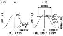
図6(A)及び図6(B)は図5に示した光Aの光度分布CA、光Bの光度分布CB、光Cの光度分布CCおよび光Dの光度分布CDを説明するための図である。詳細には、図6(A)は光Aの光度分布CA、光Bの光度分布CB、光Cの光度分布CCおよび光Dの光度分布CDのそれぞれを示した図、図6(B)は図6(A)に示した光Aの光度分布CA、光Bの光度分布CB、光Cの光度分布CCおよび光Dの光度分布CDを合成した図である。FIG6(A) and6(B) diagram for explaining the light intensity distribution CD of luminous intensity distribution CA, luminous intensity distribution CB of the light B, the optical C luminous intensity distribution CC and light D of the light A shown in FIG. 5 It is. In particular, FIG.6(A) of the light A luminous intensity distribution CA, luminous intensity distribution CB of the light B, fig showed respective luminous intensity distribution CD of luminous intensity distribution CC and light D of the light C, FIG.6(B) is luminous intensity distribution CA of light a shown in FIG.6(a), it is a view obtained by combining the luminous intensity distribution CD of luminous intensity distribution CB, the light C luminous intensity distribution CC and light D of the light B.
図6において、縦軸は光度を示しており、横軸は水平に延びている光源Sの主光軸線CL(図5参照)に対する水平方向角度(水平線H(図1参照)上角度)を示している。すなわち、「水平線H上角度0(°)」は、光源Sの主光軸線CL上を示している。 In FIG. 6, the vertical axis indicates the luminous intensity, and the horizontal axis indicates the horizontal angle (the angle above the horizontal line H (see FIG. 1)) with respect to the main optical axis CL (see FIG. 5) of the light source S extending horizontally. ing. That is, “angle 0 (°) on the horizontal line H” indicates the main optical axis line CL of the light source S.
この車両用灯具では、上述したように、指向性の高いLEDが光源Sとして用いられている。そのため、図4および図5に示すように、光源Sの主光軸線CLと小さい角度をなして光源Sから放射された光A’の光度に比べ、光源Sの主光軸線CLと大きい角度をなして光源Sから放射された光B’,C’,D’の光度がかなり低くなる。 In this vehicular lamp, an LED with high directivity is used as the light source S as described above. Therefore, as shown in FIGS. 4 and 5, the main optical axis CL of the light source S has a larger angle than the light intensity of the light A ′ emitted from the light source S at a small angle with the main optical axis CL of the light source S. The light intensity of the light B ′, C ′, D ′ radiated from the light source S is considerably low.
更に、図5に示すように、高光度の光A’が透過せしめられるレンズカットLC1の幅と、低光度の光B’が透過せしめられるレンズカットLC2の幅と、低光度の光C’が透過せしめられるレンズカットLC3の幅と、低光度の光D’が透過せしめられるレンズカットLC4の幅とが、ほぼ等しくされている。 Further, as shown in FIG. 5, the width of the lens cut LC1 through which the high-luminance light A ′ is transmitted, the width of the lens cut LC2 through which the low-luminance light B ′ is transmitted, and the low-luminance light C ′. The width of the lens cut LC3 to be transmitted and the width of the lens cut LC4 to transmit the light D ′ having a low luminous intensity are substantially equal.
また、図6(A)に示すように、光Bの光度分布CBは、光Aの光度分布CAを少し右側にオフセットさせた位置に形成されている。更に、光Cの光度分布CCは、光Bの光度分布CBを少し右側にオフセットさせた位置に形成されている。また、光Dの光度分布CDは、光Cの光度分布CCを少し右側にオフセットさせた位置に形成されている。Further, as shown in FIG. 6(A), luminous intensity distribution CB of the light B is formed at a position to offset the light intensity distribution CA of light A little to the right. Further, the light intensity distribution CC of the light C is formed at a position where the light intensity distribution CB of the light B is slightly offset to the right. The light intensity distribution CD of the light D is formed at a position where the light intensity distribution CC of the light C is slightly offset to the right.
その結果、図6(A)に示すように、光Bの光度分布CBは、光Aの光度を50%以上減少させて光Aの光度分布CAを少し右側にオフセットさせたものとほぼ等しくなる。また、光Cの光度分布CCは、光Bの光度を減少させて光Bの光度分布CBを少し右側にオフセットさせたものとほぼ等しくなる。更に、光Dの光度分布CDは、光Cの光度を減少させて光Cの光度分布CCを少し右側にオフセットさせたものとほぼ等しくなる。As a result, as shown in FIG. 6(A), luminous intensity distribution CB of the light B is substantially equal to that is slightly offset to the right side of the luminous intensity distribution CA of light A by the intensity of the light A is reduced by more than 50% . Further, the light intensity distribution CC of the light C is substantially equal to the light intensity distribution CB of the light B that is slightly offset to the right by decreasing the light intensity of the light B. Further, the light intensity distribution CD of the light D becomes substantially equal to the light intensity distribution CC of the light C that is decreased to the right by slightly decreasing the light intensity of the light C.
それゆえ、図6(B)に示すように、規格範囲の中心付近(角度0°付近)における光度が必要以上に高くなるにもかかわらず、規格範囲の右縁部付近における光度が不足してしまい、規格値を満足しなくなってしまう。換言すれば、図5および図6(B)に示すように、光源Sの主光軸線CLに沿って照射された光A,Bが必要以上に高光度になるにもかかわらず、光源Sの主光軸線CLと大きい角度をなして照射された光C,Dの光度が不足してしまう。Therefore, as shown in FIG. 6( B) , the light intensity near the right edge of the standard range is insufficient, although the light intensity near the center of the standard range (around 0 ° angle) is higher than necessary. As a result, the standard value is not satisfied. In other words, as shown in FIG. 5 and FIG. 6( B) , the light A, B irradiated along the main optical axis CL of the light source S becomes higher than necessary, but the light source S The light intensity of the lights C and D irradiated at a large angle with the main optical axis CL will be insufficient.
前記問題点に鑑み、本発明は、隣接する2つの光源の間隔を狭くし、車両用灯具全体を小型化することができる車両用灯具を提供することを目的とする。 In view of the above problems, an object of the present invention is to provide a vehicular lamp that can reduce the distance between two adjacent light sources and reduce the size of the entire vehicular lamp.
更に、本発明は、要求される光度分布に適合させるための設計変更を容易にすることができる車両用灯具を提供することを目的とする。
本発明の一局面は、車両用灯具であって、主光軸線を有する光源と、前記光源の主光軸線と所定範囲の放射角をもって放射された光を透過させる第1レンズカットと、前記第1レンズカットを透過させた光より大きな放射角をもって放射された光を透過させる第2レンズカットと、を有するレンズとが設けられている。Furthermore, an object of the present invention is to provide a vehicular lamp capable of facilitating a design change for adapting to a required light intensity distribution.
One aspect of the present invention is avehicular lamp, a light source having a main optical axis, a first lens cut for transmitting thelight emitted with a radiation angle of the main optical axis and a predetermined range of the light source, the first a second lens cut for transmitting theemitted light with a large emission angle from thelight is transmitted through the first lens cut, and a lens having a are provided.
つまり、光源の主光軸線と大きい角度をなして光源から放射された光が、光源の周囲に配置されたリフレクタ等によって光源の主光軸線の側に集光せしめられるのではなく、光源の主光軸線上に配置されたレンズの第2レンズカットによって光源の主光軸線の側に集光せしめられる。That is, the lightemitted from the light source at an angle greater the main optical axis of the light source, rather than being caused to the condenser on the side of the main optical axis of the light source by the reflector or the like arranged around the light source, the main light source The light is condensed on the main optical axis side of the light source by the second lens cut of the lens arranged on the optical axis.
そのため、光源の周囲にリフレクタなどを配置する必要が無く、光源の周囲のスペースを小さく抑えることができ、また隣接する2つの光源の間隔を狭くすることができ、それにより、車両用灯具全体を小型化することができる。 Therefore, there is no need to arrange a reflector or the like around the light source, the space around the light source can be kept small, and the interval between two adjacent light sources can be narrowed. It can be downsized.
また、リフレクタによって集光せしめられる場合よりも、要求される光度分布に適合させるための設計変更を容易にすることができる。 Moreover, the design change for adapting to the required light intensity distribution can be facilitated as compared with the case where the light is condensed by the reflector.
上記車両用灯具では、レンズにさらに第2レンズカットによる集光度合いよりも集光度合いの大きい第3レンズカットを、第2レンズカットの外側に配置することが出来る。
なお、本発明において、集光度合いとは、レンズカットを透過させた光がこのレンズ材料の有する屈折率及びこのレンズカットの形状によって定まる屈折率によって集光される割合をいう。In the vehicle lamp described above, the third lens cut having a greater concentration than the concentration by the second lens cut can be disposed outside the second lens cut.
In the present invention, the degree of light collection refers to the ratio at which light transmitted through the lens cut is collected by the refractive index of the lens material and the refractive index determined by the shape of the lens cut.
つまり、第2レンズカットを透過した光度の比較的低い光と、第3レンズカットを透過した光度の比較的低い光とが重ね合わされることになる。そして、第2レンズカットを透過した光と第3レンズカットを透過した光とが交差するように、第2レンズカットおよび第3レンズカットを構成することができる。詳細には、第3レンズカットを透過した光の外縁が、第2レンズカットを透過した光の外縁の内側に含まれるように、第2レンズカットおよび第3レンズカットを構成することができる。 That is, the light having a relatively low light intensity transmitted through the second lens cut and the light having a relatively low light intensity transmitted through the third lens cut are superimposed. The second lens cut and the third lens cut can be configured such that the light transmitted through the second lens cut and the light transmitted through the third lens cut intersect. Specifically, the second lens cut and the third lens cut can be configured such that the outer edge of the light transmitted through the third lens cut is included inside the outer edge of the light transmitted through the second lens cut.
そのため、第2レンズカットを透過した光度の比較的低い光と、第2レンズカットの外側の第3レンズカットを透過した光度の比較的低い光とが重ね合わされ、その出射部分の光度を高くすることができる。 Therefore, the light having a relatively low light intensity transmitted through the second lens cut and the light having a relatively low light intensity transmitted through the third lens cut outside the second lens cut are overlapped to increase the light intensity of the emission part. be able to.
また上記車両用灯具では、光源は主光軸線を中心として高光度の光を出射し、主光軸線との角度が大きくなるにつれ低光度の光を出射するように構成され、高光度の光が透過せしめられる第1レンズカットの幅が、低光度の光が透過せしめられる第2レンズカットの幅および第3レンズカットの幅より広くされていることが可能である。In the abovevehicle lamp, the light source is configured to emit light having a high luminous intensity centered on the main optical axis, and to emit light having a low luminous intensity as the angle with the main optical axis increases. It is possible that the width of the first lens cut to be transmitted is wider than the width of the second lens cut and the width of the third lens cut to transmit light having a low luminous intensity.
つまり、隣接するレンズカットの境界部分に高光度の光が入射せしめられないように、高光度の光が透過せしめられる第1レンズカットの幅が、低光度の光が透過せしめられる第2レンズカットの幅および第3レンズカットの幅より広くされている。 In other words, the width of the first lens cut through which the high-luminance light is transmitted is such that the low-luminance light is transmitted so that the high-luminance light does not enter the boundary between adjacent lens cuts. And the width of the third lens cut.
そのため、隣接する2つのレンズカットの境界部分に高光度の光が入射せしめられて乱反射するのに伴って、光源からの光の利用効率が低下してしまうのを回避することができる。 For this reason, it is possible to avoid a decrease in the efficiency of use of light from the light source as light having high luminous intensity is incident on the boundary portion between two adjacent lens cuts and diffusely reflected.
換言すれば、高光度の光が透過せしめられる第1レンズカットの幅が比較的狭い幅に設定されている場合よりも、光源からの光の利用効率を向上させることができる。 In other words, the use efficiency of light from the light source can be improved as compared with the case where the width of the first lens cut through which light having high luminous intensity is transmitted is set to a relatively narrow width.
上記車両用灯具では、第2レンズカットを透過した光および第3レンズカットを透過した光が、第1レンズカットを透過した光の中心に指向せしめられるのではなく、第1レンズカットを透過した光の外縁に指向せしめられるように、第2レンズカットおよび第3レンズカットを構成することができる。In thevehicular lamp, the light transmitted through the second lens cut and the light transmitted through the third lens cut are not directed to the center of the light transmitted through the first lens cut, but transmitted through the first lens cut. The second lens cut and the third lens cut can be configured to be directed to the outer edge of the light.
詳細には、第2レンズカットを透過した光の光度分布曲線のピークおよび第3レンズカットを透過した光の光度分布曲線のピークが、第1レンズカットを透過した光の光度分布曲線のピークと一致せしめられるのではなく、第1レンズカットを透過した光の光度分布曲線のピークとは異なる位置(裾部)に位置するように、第2レンズカットおよび第3レンズカットが形成されている。 Specifically, the peak of the light intensity distribution curve of the light transmitted through the second lens cut and the peak of the light intensity distribution curve of the light transmitted through the third lens cut are the peak of the light intensity distribution curve of the light transmitted through the first lens cut. The second lens cut and the third lens cut are formed so as to be positioned at positions (hems) different from the peak of the light intensity distribution curve of the light transmitted through the first lens cut, instead of being matched.
そのため、光源の主光軸線に沿って照射された光が必要以上に高光度になるにもかかわらず、光源の主光軸線と大きい角度をなして照射された光の光度が不足してしまうのを回避することができる。 Therefore, although the light irradiated along the main optical axis of the light source becomes higher than necessary, the luminous intensity of the light irradiated at a large angle with the main optical axis of the light source becomes insufficient. Can be avoided.
換言すれば、指向性の高い光源が用いられる場合であっても、光源の主光軸線に沿って照射された光が必要以上に高光度になってしまうのを回避しつつ、光源の主光軸線と大きい角度をなして照射された光の光度が不足してしまうのを回避することができる。 In other words, even when a light source with high directivity is used, the main light of the light source is avoided while avoiding that the light irradiated along the main optical axis of the light source becomes higher than necessary. It can be avoided that the intensity of light irradiated at a large angle with the axis is insufficient.
まず、本発明の車両用灯具の第1の実施形態について説明する。本発明の第1の実施形態の車両用灯具では、光源として、指向性の高いLEDが用いられる。従って、第1の実施形態の車両用灯具では、図4に示すように、LED光源の主光軸線となす角度が大きくなるに従ってLED光源から照射される光の光度が急激に低下する。 First, a first embodiment of a vehicular lamp according to the present invention will be described. In the vehicular lamp according to the first embodiment of the present invention, a highly directional LED is used as a light source. Therefore, in the vehicular lamp of the first embodiment, as shown in FIG. 4, the intensity of light emitted from the LED light source rapidly decreases as the angle formed with the main optical axis of the LED light source increases.
図7は第1の実施形態の車両用灯具の要部の斜視図である。図8は第1の実施形態の車両用灯具のレンズLSを手前側(レンズ正面側)から見た図である。 FIG. 7 is a perspective view of a main part of the vehicular lamp according to the first embodiment. FIG. 8 is a view of the lens LS of the vehicular lamp according to the first embodiment as viewed from the front side (lens front side).
第1の実施形態の車両用灯具では、図7および図8に示すように、レンズLSに35個のレンズカット1〜35が形成されている。詳細には、レンズカット1の周囲にレンズカット2,22,21,24,4,9,6,7が配列され、それらの周囲にレンズカット3,23,28,27,26,29,30,25,5,10,15,14,11,12,13,8が配列され、それらの上側にレンズカット18,17,16,19,20が配列され、下側にレンズカット33,32,31,34,35が配列されている。 In the vehicular lamp of the first embodiment, as shown in FIGS. 7 and 8, 35
図9は第1の実施形態の車両用灯具の光源SおよびレンズLSの断面図である。第1の実施形態の車両用灯具では、図7〜図9に示すように、レンズカット1の左右方向の幅が、レンズカット2,3,4,5の左右方向の幅よりも広くされている。 FIG. 9 is a cross-sectional view of the light source S and the lens LS of the vehicular lamp according to the first embodiment. In the vehicular lamp of the first embodiment, as shown in FIGS. 7 to 9, the width in the left-right direction of the
更に、第1の実施形態の車両用灯具では、図9に示すように、光源Sの主光軸線CLと比較的小さい角度である所定範囲の放射角をなして光源Sから放射された光L1’が、レンズカット1によって屈折せしめられ、レンズカット1を透過した光L1が照射方向(図9の上側)に照射される。本発明においては、放射された光L’の所定範囲の放射角としては、主光軸線CLに対して±30度が好ましい。この範囲内に放射される光は、指向性のあるLED光源などの場合、ある程度高い光度を有する。そのため、レンズカット1を通過した光は大きく屈折することなく所望の光度分布の要求を満たすことができる。 Furthermore, in the vehicular lamp of the first embodiment, as shown in FIG. 9, the light L1 emitted from the light source S with a predetermined range of emission angles that is a relatively small angle with the main optical axis CL of the light source S. 'Is refracted by the
また、第1の実施形態の車両用灯具では、光源Sから放射された光L2’が、レンズカット2によって屈折せしめられ、レンズカット2を透過した光L2が照射方向に照射される。詳細には、光源Sの主光軸線CLと光L2’とがなす角度が、光源Sの主光軸線CLと光L1’とがなす角度よりも大きくなる。更に、光L2’がレンズカット2によって屈折せしめられる角度が、光L1’がレンズカット1によって屈折せしめられる角度より大きくなる。換言すれば、光L1’よりも光源Sの主光軸線CLと大きい角度をなして光源Sから放射された光L2’が、光L1’よりも光源Sの主光軸線CLの側に大きく集光せしめられる。 Further, in the vehicular lamp of the first embodiment, the light L2 'emitted from the light source S is refracted by the
更に、第1の実施形態の車両用灯具では、光源Sから放射された光L3’が、レンズカット3によって屈折せしめられ、レンズカット3を透過した光L3が照射方向に照射される。詳細には、光源Sの主光軸線CLと光L3’とがなす角度が、光源Sの主光軸線CLと光L2’とがなす角度よりも大きくなる。更に、光L3’がレンズカット3によって屈折せしめられる角度が、光L2’がレンズカット2によって屈折せしめられる角度より大きくなる。換言すれば、光L2’よりも光源Sの主光軸線CLと大きい角度をなして光源Sから放射された光L3’が、光L2’よりも光源Sの主光軸線CLの側に大きく集光せしめられる。 Furthermore, in the vehicular lamp of the first embodiment, the light L3 'emitted from the light source S is refracted by the
図10(A)及び図10(B)は図9に示した光L1の光度分布C1、光L2の光度分布C2および光L3の光度分布C3を説明するための図である。詳細には、図10(A)は光L1の光度分布C1、光L2の光度分布C2および光L3の光度分布C3のそれぞれを示した図、図10(B)は図10(A)に示した光L1の光度分布C1、光L2の光度分布C2および光L3の光度分布C3を合成した図である。FIGS.10(A) and 10(B) is a diagram for explaining the light intensity distribution C1, the luminous intensity distribution C3 luminous intensity distribution C2 and light L3 of the light L2 of the light L1 shown in FIG. In particular, FIG.10(A) is the luminous intensity distribution C1 of the light L1, illustrates the respective luminous intensity distributions C3 luminous intensity distribution C2 and light L3 of the light L2,FIG. 10(B) shown in FIG.10(A) FIG. 6 is a diagram in which a light intensity distribution C1 of light L1, a light intensity distribution C2 of light L2, and a light intensity distribution C3 of light L3 are combined.
図10において、縦軸は光度を示しており、横軸は水平に延びている光源Sの主光軸線CL(図9参照)に対する水平方向角度(水平線H(図1参照)上角度)を示している。すなわち、「水平線H上角度0(°)」は、光源Sの主光軸線CL上を示している。 10, the vertical axis indicates the luminous intensity, and the horizontal axis indicates the horizontal angle (the angle above the horizontal line H (see FIG. 1)) with respect to the main optical axis CL (see FIG. 9) of the light source S extending horizontally. ing. That is, “angle 0 (°) on the horizontal line H” indicates the main optical axis line CL of the light source S.
第1の実施形態の車両用灯具では、上述したように、指向性の高いLEDが光源Sとして用いられている。そのため、図4および図9に示すように、光源Sの主光軸線CLと小さい角度(所定範囲の放射角)をなして光源Sから放射された光L1’の光度に比べ、光源Sの主光軸線CLと大きい角度をなして光源Sから放射された光L2’,L3’の光度がかなり低くなる。 In the vehicular lamp according to the first embodiment, as described above, a highly directional LED is used as the light source S. Therefore, as shown in FIG. 4 and FIG. 9, the main light source S is compared with the light intensity of the light L1 ′ emitted from the light source S at a small angle (radiation angle within a predetermined range) with the main optical axis CL of the light source S. The light intensity of the light L2 ′ and L3 ′ emitted from the light source S at a large angle with the optical axis CL becomes considerably low.
そこで、第1の実施形態の車両用灯具では、図9に示すように、レンズカット2による集光度合いよりも集光度合いの大きいレンズカット3が、レンズカット2の外側に配置されている。つまり、第1の実施形態の車両用灯具では、図9に示すように、レンズカット2を透過した光度の比較的低い光L2と、レンズカット3を透過した光度の比較的低い光L3とが重ね合わされている。換言すれば、第1の実施形態の車両用灯具では、図10(A)に示すように、光L2の光度分布C2と光L3の光度分布C3とが重ね合わされている。Therefore, in the vehicular lamp according to the first embodiment, as shown in FIG. 9, the lens cut 3 having a greater degree of light collection than the
詳細には、第1の実施形態の車両用灯具では、図9に示すように、レンズカット2を透過した光L2とレンズカット3を透過した光L3とが交差するように、レンズカット2およびレンズカット3が形成されている。更に詳細には、第1の実施形態の車両用灯具では、レンズカット3を透過した光L3の外縁が、レンズカット2を透過した光L2の外縁の内側に含まれるように、つまり、図10(A)に示すように、光L3の光度分布C3が光L2の光度分布C2に含まれるように、レンズカット2およびレンズカット3が形成されている。Specifically, in the vehicular lamp according to the first embodiment, as shown in FIG. 9, the
そのため、第1の実施形態の車両用灯具によれば、図10(B)に示すように、レンズカットLC3を透過した光度の比較的低い光Cと、レンズカットLC3の外側のレンズカットLC4を透過した光度の比較的低い光Dとが重ね合わされることなく照射される図5および図6に示した本発明に関連する従来の車両用灯具よりも、光源Sの主光軸線CLと大きい角度をなして照射された光L2,L3(図9参照)により照射する領域の光度(C2+C3)を高くすることができる。Therefore, according to the vehicular lamp of the first embodiment, as shown in FIG. 10B, the light C having a relatively low light intensity transmitted through the lens cut LC3 and the lens cut LC4 outside the lens cut LC3 are provided. relatively low light D and than 5 and a conventional vehicle lighting device related to the present invention shown in FIG. 6 is irradiated without beingsuperposed, a large angle with the main optical axis CL of the light source S of the transmitted light intensity It is possible to increase the luminous intensity (C2 + C3) of the region irradiated with the light L2 and L3 (see FIG. 9) irradiated with the above.
更に、第1の実施形態の車両用灯具では、上述した本発明に関連する従来の車両用灯具とは異なり、図7〜図9に示すように、高光度の光L1’が透過せしめられるレンズカット1の幅が、低光度の光L2’が透過せしめられるレンズカット2の幅および低光度の光L3’が透過せしめられるレンズカット3の幅よりも広くされている。 Furthermore, in the vehicular lamp according to the first embodiment, unlike the conventional vehicular lamp related to the present invention described above, as shown in FIGS. 7 to 9, a lens through which light L1 ′ having a high luminous intensity is transmitted. The width of the
つまり、図5および図6に示した本発明に関連する技術による車両用灯具のように、隣接する2つのレンズカットLC1,LC2の境界部分に高光度の光A,Bが入射せしめられてしまうのを回避するために、第1の実施形態の車両用灯具では、図9に示すように、高光度の光L1’が透過せしめられるレンズカット1の幅が、低光度の光L2’が透過せしめられるレンズカット2の幅および低光度の光L3’が透過せしめられるレンズカット3の幅より広くされている。 That is, like the vehicular lamp according to the technology related to the present invention shown in FIG. 5 and FIG. 6, the high-intensity lights A and B are incident on the boundary portion between the two adjacent lens cuts LC1 and LC2. In order to avoid this, in the vehicular lamp of the first embodiment, as shown in FIG. 9, the width of the lens cut 1 through which the light L1 ′ having high luminous intensity is transmitted is low and the light L2 ′ having low luminous intensity is transmitted. The width of the lens cut 2 to be squeezed and the width of the lens cut 3 to which the low light intensity light L3 ′ is transmitted are set.
そのため、第1の実施形態の車両用灯具によれば、図5および図6に示した本発明に関連する従来技術による車両用灯具のように、隣接する2つのレンズカットLC1,LC2の境界部分に高光度の光A’,B’が入射せしめられて乱反射するのに伴って、光源Sからの光A’,B’の利用効率が低下してしまうのを回避することができる。 Therefore, according to the vehicular lamp of the first embodiment, as in the vehicular lamp according to the related art shown in FIGS. 5 and 6, the boundary portion between two adjacent lens cuts LC1 and LC2 It is possible to avoid a decrease in the utilization efficiency of the light A ′ and B ′ from the light source S as the light A ′ and B ′ having high luminous intensity is incident and diffusely reflected.
換言すれば、第1の実施形態の車両用灯具によれば、図5および図6に示した本発明に関連する他の技術による車両用灯具のように、高光度の光A’,B’が透過せしめられるレンズカットLC1,LC2の幅が比較的狭い幅に設定されている場合よりも、光源Sからの光L1’(図9参照)の利用効率を向上させることができる。 In other words, according to the vehicular lamp of the first embodiment, high-luminance light A ′, B ′, as in the vehicular lamp according to another technique related to the present invention shown in FIG. 5 and FIG. The efficiency of using the light L1 ′ (see FIG. 9) from the light source S can be improved as compared with the case where the lens cuts LC1 and LC2 through which light is transmitted are set to be relatively narrow.
更に、第1の実施形態の車両用灯具では、図9および図10(A)に示すように、レンズカット2を透過した光L2およびレンズカット3を透過した光L3が、レンズカット1を透過した光L1の中心(光度分布C1の中心)に指向せしめられるのではなく、レンズカット1を透過した光L1の外縁(光度分布C1の外縁、規格範囲の右縁部(図10(B)参照))に指向せしめられるように、レンズカット2およびレンズカット3が形成されている。Furthermore, transmission in the vehicle lighting device of the first embodiment, as shown in FIG. 9 and FIG. 10(A), the light L3 having passed through the light L2 and the
即ちレンズカット2を透過した光L2の光度分布C2のピークおよびレンズカット3を透過した光L3の光度分布C3のピークが、レンズカット1を透過した光L1の光度分布C1のピークと一致せしめられるのではなく、レンズカット1を透過した光L1の光度分布C1の裾部に位置するように、レンズカット2およびレンズカット3が形成されている。 That is, the peak of the light intensity distribution C2 of the light L2 transmitted through the
そのため、第1の実施形態の車両用灯具によれば、図5および図6に示した本発明に関連する他の技術による車両用灯具のように、光源Sの主光軸線CLに沿って照射された光A,Bの光度(CA+CB)が必要以上に高くなるにもかかわらず、光源Sの主光軸線CLと大きい角度をなして照射された光C,Dの光度(CC+CD)が不足してしまうのを回避することができる。Therefore, according to the vehicular lamp of the first embodiment, irradiation is performed along the main optical axis CL of the light source S as in the vehicular lamp according to another technique related to the present invention shown in FIGS. 5 and 6. Although the light intensity (CA + CB) of the emitted light A, B is higher than necessary, the light intensity (CC + CD) of the light C, D irradiated at a large angle with the main optical axis CL of the light source S is insufficient. Can be avoided.
換言すれば、第1の実施形態の車両用灯具によれば、指向性の高いLED光源Sが用いられる場合であっても、光源Sの主光軸線CLに沿って照射された光の光度(規格範囲の中心付近の光度(図10(B)参照)が必要以上に高くなってしまうのを回避しつつ、光源Sの主光軸線CLと大きい角度をなして照射された光の光度(規格範囲の右縁部付近の光度(図10(B)参照))が不足してしまうのを回避することができる。 In other words, according to the vehicular lamp of the first embodiment, even when a highly directional LED light source S is used, the luminous intensity of light irradiated along the main optical axis CL of the light source S ( While avoiding that the luminous intensity near the center of the standard range (see FIG. 10B) becomes unnecessarily high, the luminous intensity of the light irradiated at a large angle with the main optical axis CL of the light source S (standard) It can be avoided that the light intensity in the vicinity of the right edge of the range (see FIG. 10B) is insufficient.
図11は第1の実施形態の車両用灯具の光源SおよびレンズLSの図9と同様の断面図である。 FIG. 11 is a cross-sectional view similar to FIG. 9 of the light source S and the lens LS of the vehicular lamp according to the first embodiment.
第1の実施形態の車両用灯具では、図11に示すように、光源Sから放射された光L4’が、レンズカット4によって屈折せしめられ、レンズカット4を透過した光L4が照射方向(図11の上側)に照射される。詳細には、光源Sの主光軸線CLと光L4’とがなす角度が、光源Sの主光軸線CLと光L1’とがなす角度(所定範囲の放射角)よりも大きくなる。更に、光L4’がレンズカット4によって屈折せしめられる角度が、光L1’がレンズカット1によって屈折せしめられる角度より大きくなる。換言すれば、光L1’よりも光源Sの主光軸線CLと大きい角度をなして光源Sから放射された光L4’が、光L1’よりも光源Sの主光軸線CLの側に大きく集光せしめられる。 In the vehicular lamp of the first embodiment, as shown in FIG. 11, the light L4 ′ emitted from the light source S is refracted by the
更に、第1の実施形態の車両用灯具では、光源Sから放射された光L5’が、レンズカット5によって屈折せしめられ、レンズカット5を透過した光L5が照射方向(図11の上側)に照射される。詳細には、光源Sの主光軸線CLと光L5’とがなす角度が、光源Sの主光軸線CLと光L4’とがなす角度よりも大きくなる。更に、光L5’がレンズカット5によって屈折せしめられる角度が、光L4’がレンズカット4によって屈折せしめられる角度より大きくなる。換言すれば、光L4’よりも光源Sの主光軸線CLと大きい角度をなして光源Sから放射された光L5’が、光L4’よりも光源Sの主光軸線CLの側に大きく集光せしめられる。 Furthermore, in the vehicular lamp of the first embodiment, the light L5 ′ emitted from the light source S is refracted by the
図12(A)及び図12(B)は図11に示した光L1の光度分布C1、光L4の光度分布C4および光L5の光度分布C5を説明するための図である。詳細には、図12(A)は光L1の光度分布C1、光L4の光度分布C4および光L5の光度分布C5をそれぞれ示した図、図12(B)は図12(A)に示した光L1の光度分布C1、光L4の光度分布C4および光L5の光度分布C5を合成した図である。Figure12(A) andFIG. 12(B) is a diagram for explaining the light intensity distribution C1, the luminous intensity distribution C5 luminous intensity distribution C4 and light L5 of the light L4 of the light L1 shown in FIG. 11. In particular, FIG.12(A) is a diagram illustrating luminous intensity distribution C1 of the light L1, the intensity distribution C5 luminous intensity distribution C4 and light L5 of the light L4, respectively, and FIG.12(B) is shown in FIG.12(A) It is the figure which synthesize | combined the luminous intensity distribution C1 of the light L1, the luminous intensity distribution C4 of the light L4, and the luminous intensity distribution C5 of the light L5.
図12において、縦軸は光度を示しており、横軸は水平に延びている光源Sの主光軸線CL(図11参照)に対する水平方向角度(水平線H(図1参照)上角度)を示している。即ち、「水平線H上角度0(°)」は、光源Sの主光軸線CL上を示している。 In FIG. 12, the vertical axis represents the luminous intensity, and the horizontal axis represents the horizontal angle (the angle above the horizontal line H (see FIG. 1)) with respect to the main optical axis CL (see FIG. 11) of the light source S extending horizontally. ing. That is, “angle 0 (°) on the horizontal line H” indicates the main optical axis line CL of the light source S.
第1の実施形態の車両用灯具では、上述したように、指向性の高いLEDが光源Sとして用いられている。そのため、図4および図11に示すように、光源Sの主光軸線CLと小さい角度(所定範囲の放射角)をなして光源Sから放射された光L1’の光度に比べ、光源Sの主光軸線CLと大きい角度をなして光源Sから放射された光L4’,L5’の光度がかなり低くなる。 In the vehicular lamp according to the first embodiment, as described above, a highly directional LED is used as the light source S. Therefore, as shown in FIG. 4 and FIG. 11, the main light source S of the light source S is compared with the light intensity of the light L1 ′ emitted from the light source S at a small angle (radiation angle within a predetermined range) with the main optical axis CL of the light source S. The luminous intensity of the light L4 ′ and L5 ′ emitted from the light source S at a large angle with the optical axis CL becomes considerably low.
そこで、第1の実施形態の車両用灯具では、図11に示すように、レンズカット4による集光度合いよりも集光度合いの大きいレンズカット5が、レンズカット4の外側に配置されている。つまり、第1の実施形態の車両用灯具では、図11に示すように、レンズカット4を透過した光度の比較的低い光L4と、レンズカット5を透過した光度の比較的低い光L5とが重ね合わされている。換言すれば、第1の実施形態の車両用灯具では、図12(A)に示すように、光L4の光度分布C4と光L5の光度分布C5とが重ね合わされている。Therefore, in the vehicular lamp according to the first embodiment, as shown in FIG. 11, the lens cut 5 having a greater degree of light collection than the
詳細には、第1の実施形態の車両用灯具では、図11に示すように、レンズカット4を透過した光L4とレンズカット5を透過した光L5とが交差するように、レンズカット4およびレンズカット5が形成されている。更に詳細には、第1の実施形態の車両用灯具では、レンズカット5を透過した光L5の外縁が、レンズカット4を透過した光L4の外縁の内側に含まれるように、つまり、図12(A)に示すように、光L5の光度分布C5が光L4の光度分布C4に含まれるように、レンズカット4およびレンズカット5が形成されている。Specifically, in the vehicular lamp of the first embodiment, as shown in FIG. 11, the
そのため、第1の実施形態の車両用灯具によれば、図12(B)に示すように、レンズカットLC3を透過した光度の比較的低い光Cと、レンズカットLC3の外側のレンズカットLC4を透過した光度の比較的低い光Dとが重ね合わされることなく照射される図5および図6に示した本発明に関連する他の技術による車両用灯具よりも、光源Sの主光軸線CLと大きい角度をなして照射された光L4,L5(図11参照)の光度(C4+C5)を高くすることができる。Therefore, according to the vehicular lamp of the first embodiment, as shown in FIG. 12( B) , the light C having a relatively low luminous intensity transmitted through the lens cut LC3 and the lens cut LC4 outside the lens cut LC3 are provided. the transmitted than vehicle lamp according to a relatively low light D and other techniques related to the present invention shown in FIGS. 5 and 6 is irradiated without being superimposedluminosity, and the main optical axis CL of the light source S The luminous intensity (C4 + C5) of the light L4 and L5 (see FIG. 11) irradiated at a large angle can be increased.
更に、第1の実施形態の車両用灯具では、上述した本発明に関連する他の技術による車両用灯具とは異なり、図7、図8および図11に示すように、高光度の光L1’が透過せしめられるレンズカット1の幅が、低光度の光L4’が透過せしめられるレンズカット4の幅および低光度の光L5’が透過せしめられるレンズカット5の幅よりも広くされている。Furthermore, inthe vehicle lamp of the first embodiment, unlike the above-described vehicle lamp according to another technique related to the present invention, as shown in FIGS. 7, 8, and 11, the light L1 ′ having a high luminous intensity is used. Is wider than the width of the lens cut 4 through which the low light intensity light L4 ′ is transmitted and the width of the lens cut 5 through which the low light intensity light L5 ′ is transmitted.
つまり、図5および図6に示した本発明に関連する他の技術による車両用灯具のように、隣接する2つのレンズカットLC1,LC2の境界部分に高光度の光A,Bが入射せしめられてしまうのを回避するために、第1の実施形態の車両用灯具では、図11に示すように、高光度の光L1’が透過せしめられるレンズカット1の幅が、低光度の光L4’が透過せしめられるレンズカット4の幅および低光度の光L5’が透過せしめられるレンズカット5の幅より広くされている。 That is, as in the case of a vehicle lamp according to another technology related to the present invention shown in FIGS. 5 and 6, the high-intensity lights A and B are incident on the boundary portion between the two adjacent lens cuts LC <b> 1 and LC <b> 2. In the vehicular lamp according to the first embodiment, as shown in FIG. 11, the width of the lens cut 1 through which the high-luminance light L1 ′ is transmitted has a low-luminance light L4 ′. Is wider than the width of the lens cut 4 through which light is transmitted and the width of the lens cut 5 through which light L5 ′ having a low luminous intensity is transmitted.
そのため、第1の実施形態の車両用灯具によれば、図5および図6に示した本発明に関連する他の技術による車両用灯具のように、隣接する2つのレンズカットLC1,LC2の境界部分に高光度の光A’,B’が入射せしめられて乱反射するのに伴って、光源Sからの光A’,B’の利用効率が低下してしまうのを回避することができる。Therefore, according to the vehicular lamp of the first embodiment, like the vehicular lamp according to another technique related to the present invention shown in FIGS. 5 and 6, the boundary between two adjacent lens cuts LC <b> 1 and LC <b> 2. high intensity of light a in the portion ', B' are accompanied to irregular reflection is caused to incident light a from the light source S ', B' utilization efficiency can be preventedfrom being lowered.
換言すれば、第1の実施形態の車両用灯具によれば、図5および図6に示した本発明に関連する他の技術による車両用灯具のように、高光度の光A’,B’が透過せしめられるレンズカットLC1,LC2の幅が比較的狭い幅に設定されている場合よりも、光源Sからの光L1’(図11参照)の利用効率を向上させることができる。In other words, according to the vehicular lamp of the first embodiment , high-luminance light A ′, B ′, as in the vehicular lamp according to another technique related to the present invention shown in FIG. 5 and FIG. There than the width of the lens cut LC1, LC2 induced to transmission is set to a relatively smallwidth, the light L1 from the light source S 'can improve the utilization efficiency (see FIG. 11).
更に、第1の実施形態の車両用灯具では、図11および図12(A)に示すように、レンズカット4を透過した光L4およびレンズカット5を透過した光L5が、レンズカット1を透過した光L1の中心(光度分布C1の中心)に指向せしめられるのではなく、レンズカット1を透過した光L1の外縁(光度分布C1の外縁、規格範囲の左縁部(図12(B)参照))に指向せしめられるように、レンズカット4およびレンズカット5が形成されている。Furthermore, in the vehicular lamp of the first embodiment, as shown in FIGS. 11 and 12( A) , the light L4 transmitted through the
詳細には、レンズカット4を透過した光L4の光度分布C4のピークおよびレンズカット5を透過した光L5の光度分布C5のピークが、レンズカット1を透過した光L1の光度分布C1のピークと一致せしめられないように、レンズカット4およびレンズカット5が形成されている。この場合において、レンズカット4およびレンズカット5は、例えばレンズカット1を透過した光L1の光度分布C1の裾のような部分に位置するように、あるいは、光度分布C4と光度分布C5のピークを光度分布C1上の同等の光度と一致する位置となるように、形成されている。 Specifically, the peak of the light intensity distribution C4 of the light L4 transmitted through the
そのため、第1の実施形態の車両用灯具によれば、図5および図6に示した本発明に関連する他の技術による車両用灯具のように、光源Sの主光軸線CLに沿って照射された光A,Bの光度(CA+CB)が必要以上に高くなるにもかかわらず、光源Sの主光軸線CLと大きい角度をなして照射された光C,Dの光度(CC+CD)が不足してしまうのを回避することができる。Therefore, according to the vehicular lamp of the first embodiment, irradiation is performed along the main optical axis CL of the light source S as in the vehicular lamp according to another technique related to the present invention shown in FIGS. 5 and 6. light a, despite the B luminosity (CA + CB) is higher thannecessary, the light source main optical axis CL and a large angle without light irradiated by C of S, insufficient D luminosity (CC + CD) is Can be avoided.
換言すれば、第1の実施形態の車両用灯具によれば、指向性の高いLED光源Sが用いられる場合であっても、光源Sの主光軸線CLに沿って照射された光の光度(規格範囲の中心付近の光度(図12(B)参照)が必要以上に高くなってしまうのを回避しつつ、光源Sの主光軸線CLと大きい角度をなして照射された光の光度(規格範囲の左縁部付近の光度(図12(B)参照))が不足してしまうのを回避することができる。In other words, according to the vehicular lamp of the first embodiment, even when a highly directional LED light source S is used, the luminous intensity of light irradiated along the main optical axis CL of the light source S ( while avoiding the luminous intensity near the center of the specified range (see FIG. 12(B)) becomes higher than necessary, the light source S of the main optical axis CL irradiated at an large angle with the light intensity (standard range left edge near the light intensity (see FIG. 12(B))) can be prevented from being insufficient.
図1に示すようなリアフォグランプの配光規格では、上下方向(鉛直方向)の規格範囲の幅が、左右方向(水平方向)の規格範囲の幅よりも狭くなっている。従って、第1の実施形態の車両用灯具がリアフォグランプに適用される場合には、図4に示すように光源の主光軸線となす角度が大きくなるに従って光源から照射される光の光度が急激に低下するLED光源が用いられても、規格範囲の上縁部および下縁部の光度が不足してしまうおそれはない。 In the rear fog lamp light distribution standard as shown in FIG. 1, the width of the standard range in the vertical direction (vertical direction) is narrower than the width of the standard range in the horizontal direction (horizontal direction). Therefore, when the vehicular lamp according to the first embodiment is applied to a rear fog lamp, as the angle formed with the main optical axis of the light source becomes larger as shown in FIG. Even if an LED light source that decreases rapidly is used, there is no possibility that the luminous intensity of the upper edge and the lower edge of the standard range will be insufficient.
この点に鑑み、第1の実施形態の車両用灯具では、図9および図10に示すように、光L2および光L3が光L1の外縁(光度分布C1の外縁、規格範囲の右縁部(図10(B)参照))に指向せしめられ、図11および図12に示すように、光L4および光L5が光L1の外縁(光度分布C1の外縁、規格範囲の左縁部(図12(B)参照))に指向せしめられる。一方、レンズカット6,11,16(図7および図8参照)を透過した光は、規格範囲の上縁(図1中の「5°U」線付近)に指向せしめられず、また、レンズカット21,26,31(図7および図8参照)を透過した光も、規格範囲の下縁(図1中の「5°D」線付近)に指向せしめられない。In view of this point, in the vehicular lamp of the first embodiment, as shown in FIGS. 9 and 10, the light L2 and the light L3 are emitted from the outer edge of the light L1 (the outer edge of the light intensity distribution C1, the right edge of the standard range ( is allowed directed to FIG.10(B) refer)), as shown in FIGS. 11 and 12, the outer edge of the outer edge (luminous intensity distribution C1 of the light L4 and light L5 light L1, left edge of the specified range (FIG. 12( B) See))). On the other hand, the light transmitted through the
詳細には、第1の実施形態の車両用灯具では、レンズカット6,11,16(図7および図8参照)を透過した光が、例えば規格範囲の中心(図1中の水平線H付近)に指向せしめられ、また、レンズカット21,26,31(図7および図8参照)を透過した光が、例えば規格範囲の中心(図1中の水平線H付近)に指向せしめられている。 Specifically, in the vehicular lamp of the first embodiment, the light transmitted through the
また、第1の実施形態の車両用灯具では、レンズLSの右上部のレンズカット7,8,12,13,17,18(図7および図8参照)、右下部のレンズカット22,23,27,28,32,33(図7および図8参照)、左上部のレンズカット9,10,14,15,19,20(図7および図8参照)、および左下部のレンズカット24,25,29,30,34,35(図7および図8参照)には、拡散機能のみが備えられ、光を指向させる機能は備えられていなくてもよい。 In the vehicular lamp of the first embodiment, the
第2の実施形態の車両用灯具では、代わりに、レンズLSの右上部のレンズカット7,8,12,13,17,18、右下部のレンズカット22,23,27,28,32,33、左上部のレンズカット9,10,14,15,19,20、および左下部のレンズカット24,25,29,30,34,35の少なくとも一部に、光を指向させる機能を備えることも可能である。 In the vehicular lamp of the second embodiment, instead, the
具体的には、例えばレンズLSの右上部のレンズカット7および左上部のレンズカット14に、光を指向させる機能が備えられている。 Specifically, for example, the lens cut 7 in the upper right part and the lens cut 14 in the upper left part of the lens LS are provided with a function of directing light.
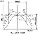
図13は第2の実施形態の車両用灯具の光度分布を説明するための図である。詳細には、図13はレンズカット1を透過した光の光度分布C1、レンズカット2を透過した光の光度分布C2、レンズカット3を透過した光の光度分布C3、レンズカット4を透過した光の光度分布C4、レンズカット5を透過した光の光度分布C5、レンズカット7を透過した光の光度分布C7、および、レンズカット14を透過した光の光度分布C14を合成した図である。 FIG. 13 is a diagram for explaining the light intensity distribution of the vehicular lamp according to the second embodiment. Specifically, FIG. 13 shows the light intensity distribution C1 of the light transmitted through the
図13において、縦軸は光度を示しており、横軸は水平に延びている光源S(図7参照)の主光軸線に対する水平方向角度(水平線H(図1参照)上角度)を示している。すなわち、「水平線H上角度0(°)」は、光源Sの主光軸線上を示している。 In FIG. 13, the vertical axis indicates the luminous intensity, and the horizontal axis indicates the horizontal angle (the angle above the horizontal line H (see FIG. 1)) with respect to the main optical axis of the light source S (see FIG. 7) extending horizontally. Yes. That is, “angle 0 (°) on the horizontal line H” indicates the main optical axis of the light source S.
第2の実施形態の車両用灯具では、図13に示すように、レンズカット2を透過した光およびレンズカット3を透過した光が、レンズカット1を透過した光の外縁(光度分布C1の外縁、規格範囲の右縁部)に指向せしめられるのみならず、レンズカット7を透過した光が、レンズカット1を透過した光の外縁(光度分布C1の外縁、規格範囲の右縁部)に指向せしめられており、それにより、光度分布C1の外縁(規格範囲の右縁部)の光度不足が補われている。 In the vehicular lamp of the second embodiment, as shown in FIG. 13, the light transmitted through the
また、第2の実施形態の車両用灯具では、図13に示すように、レンズカット4を透過した光およびレンズカット5を透過した光が、レンズカット1を透過した光の外縁(光度分布C1の外縁、規格範囲の左縁部)に指向せしめられるのみならず、レンズカット14を透過した光が、レンズカット1を透過した光の外縁(光度分布C1の外縁、規格範囲の左縁部)に指向せしめられており、それにより、光度分布C1の外縁(規格範囲の左縁部)の光度不足が補われている。 In the vehicular lamp of the second embodiment, as shown in FIG. 13, the light transmitted through the
第1の実施形態の車両用灯具では、図7および図8に示すように、1個の光源Sが設けられているが、代わりに、複数の光源を設けることも可能である。 In the vehicular lamp of the first embodiment, as shown in FIGS. 7 and 8, one light source S is provided, but a plurality of light sources may be provided instead.
図14に、4個の光源(図示せず)が設けられた場合の第3の実施形態の車両用灯具をしめす。ここはレンズLS’を手前側から見た図8と同様の図である。第3の実施形態の車両用灯具では、図14に示すように、第1の実施形態の車両用灯具のレンズLS(図8参照)と同様に構成されたレンズ部LS−1,LS−2,LS−3,LS−4を4個有するレンズLS’が用いられている。 FIG. 14 shows the vehicular lamp of the third embodiment in the case where four light sources (not shown) are provided. This is a view similar to FIG. 8 when the lens LS ′ is viewed from the front side. In the vehicular lamp of the third embodiment, as shown in FIG. 14, lens portions LS-1 and LS-2 having the same configuration as the lens LS (see FIG. 8) of the vehicular lamp of the first embodiment. , LS-3, LS-4, and four lenses LS ′ are used.
第3の実施形態の車両用灯具では、第1および第2の実施形態と同様に、光源の主光軸線と大きい角度をなして光源から放射された光が、リフレクタによってではなく、光源の主光軸線上に配置されたレンズLS’のレンズカットによって光源の主光軸線の側に集光せしめられる。 In the vehicular lamp of the third embodiment, as in the first and second embodiments, the light emitted from the light source at a large angle with the main optical axis of the light source is not reflected by the reflector, but by the main light source. The light is condensed on the main optical axis side of the light source by the lens cut of the lens LS ′ arranged on the optical axis.
そのため、第3の実施形態の車両用灯具によれば、リフレクタによって集光せしめられる場合よりも、光源の周囲のスペースを小さく抑えることができる。つまり、レンズ部LS−1,LS−2,LS−3,LS−4を互いに近接させて配列することができる。 Therefore, according to the vehicular lamp of the third embodiment, the space around the light source can be kept smaller than when the light is condensed by the reflector. That is, the lens portions LS-1, LS-2, LS-3, and LS-4 can be arranged close to each other.
換言すれば、隣接する2つの光源の間隔を狭くすることができる。それにより、車両用灯具全体を小型化することができる。 In other words, the interval between two adjacent light sources can be reduced. Thereby, the whole vehicle lamp can be reduced in size.
また、第3の実施形態の車両用灯具によれば、1個の基板によって複数の光源を支持することができる。 Moreover, according to the vehicle lamp of the third embodiment, a plurality of light sources can be supported by a single substrate.
また、リフレクタの場合よりも、要求される光度分布に適合させるための設計変更を容易にすることができる。 In addition, it is possible to facilitate a design change for adapting to a required light intensity distribution as compared with the case of a reflector.
第1の実施形態の車両用灯具では、レンズカット1の周囲に34個のレンズカット2〜35が配列されているが、本発明はこれに限定されず、代わりに、レンズカット1の周囲に任意の数のレンズカットを配列することが可能である。 In the vehicular lamp of the first embodiment, 34
また、第3の実施形態の車両用灯具では、4個の光源が設けられているが、本発明はこれに限定されず、代わりに、4個以外の任意の数の光源を設けることも可能である。 In the vehicle lamp of the third embodiment, four light sources are provided. However, the present invention is not limited to this, and an arbitrary number of light sources other than four can be provided instead. It is.
上述した実施形態を適宜組み合わせることも可能である。 It is also possible to combine the above-described embodiments as appropriate.
S 光源
CL 主光軸線
LS レンズ
1,2,3,4,5 レンズカット
L1,L2,L3 光
L1’,L2’,L3’ 光S light source CL main optical
Claims (3)
Translated fromJapaneseLED光源の主光軸線上に配置された第1レンズカットと、第1レンズカットよりもLED光源の主光軸線から離れた位置に配置された第2レンズカットと、第2レンズカットよりもLED光源の主光軸線から離れた位置に配置された第3レンズカットとを有するレンズとを具備する車両用灯具において、
LED光源の主光軸線と第1の角度をなしてLED光源からLED光源の主光軸線の一方の側に放射された第1の光が、第1レンズカットを透過せしめられると、その透過光がLED光源の主光軸線と第2の角度をなしてLED光源の主光軸線の一方の側に照射されるように、第1レンズカットを形成し、
LED光源の主光軸線と第1の角度より大きい第3の角度をなしてLED光源からLED光源の主光軸線の一方の側に放射された第2の光が、第2レンズカットを透過せしめられると、その透過光がLED光源の主光軸線と第2の角度より小さい第4の角度をなしてLED光源の主光軸線の一方の側に照射されるように、第2レンズカットを形成し、
LED光源の主光軸線と第3の角度より大きい第5の角度をなしてLED光源からLED光源の主光軸線の一方の側に放射された第3の光が、第2レンズカットを透過せしめられると、その透過光がLED光源の主光軸線と第6の角度をなしてLED光源の主光軸線の一方の側に照射されるように、第2レンズカットを形成し、
LED光源の主光軸線と第5の角度より大きい第7の角度をなしてLED光源からLED光源の主光軸線の一方の側に放射された第4の光が、第3レンズカットを透過せしめられると、その透過光がLED光源の主光軸線と第6の角度より小さい第8の角度をなしてLED光源の主光軸線の一方の側に照射されるように、第3レンズカットを形成し、
第2レンズカットを透過した光の光度分布曲線のピークおよび第3レンズカットを透過した光の光度分布曲線のピークが、第1レンズカットを透過した光の光度分布曲線の裾部であって、LED光源の主光軸線の一方の側の裾部に位置するように、第2レンズカットおよび第3レンズカットを形成したことを特徴とする車両用灯具。AnLED light sourcethat emits light having apeak of intensity distribution curve on the main optical axis,
Afirst lens cut disposed on the main optical axis of the LED light source, a second lens cut disposed at a position farther from the main optical axis of the LED light source than the first lens cut, and an LED than the second lens cut In a vehicle lamp comprising: a lens having a third lens cut disposed at a position away from the main optical axis of the light source;
When the first light emitted from the LED light source to one side of the main optical axis of the LED light source at a first angle with the main optical axis of the LED light source is transmitted through the first lens cut, the transmitted light is transmitted. Forming a first lens cut such that is irradiated to one side of the main optical axis of the LED light source at a second angle with the main optical axis of the LED light source,
The second light emitted from the LED light source to one side of the main optical axis of the LED light source at a third angle larger than the first angle with the main optical axis of the LED light source transmits the second lens cut. The second lens cut is formed so that the transmitted light is irradiated to one side of the main optical axis of the LED light source at a fourth angle smaller than the second angle with the main optical axis of the LED light source. And
The third light emitted from the LED light source to one side of the main optical axis of the LED light source at a fifth angle larger than the third angle with the main optical axis of the LED light source transmits the second lens cut. The second lens cut is formed so that the transmitted light is irradiated to one side of the main optical axis of the LED light source at a sixth angle with the main optical axis of the LED light source,
The fourth light emitted from the LED light source to one side of the main optical axis of the LED light source at a seventh angle larger than the fifth angle with the main optical axis of the LED light source transmits the third lens cut. The third lens cut is formed so that the transmitted light is irradiated to one side of the main optical axis of the LED light source at an eighth angle smaller than the sixth angle with the main optical axis of the LED light source. And
The peak of the light intensity distribution curve of the light transmitted through the second lens cut and the peak of the light intensity distribution curve of the light transmitted through the third lens cut are the skirts of the light intensity distribution curve of the light transmitted through the first lens cut, A vehicular lamp characterized in that a second lens cut and a third lens cut are formed so as to be positioned at a skirt portion on one side of a main optical axis of an LED light source.
Priority Applications (1)
| Application Number | Priority Date | Filing Date | Title |
|---|---|---|---|
| JP2007083304AJP4651120B2 (en) | 2006-03-29 | 2007-03-28 | Vehicle lighting |
Applications Claiming Priority (2)
| Application Number | Priority Date | Filing Date | Title |
|---|---|---|---|
| JP2006090949 | 2006-03-29 | ||
| JP2007083304AJP4651120B2 (en) | 2006-03-29 | 2007-03-28 | Vehicle lighting |
Publications (2)
| Publication Number | Publication Date |
|---|---|
| JP2007294434A JP2007294434A (en) | 2007-11-08 |
| JP4651120B2true JP4651120B2 (en) | 2011-03-16 |
Family
ID=38764815
Family Applications (1)
| Application Number | Title | Priority Date | Filing Date |
|---|---|---|---|
| JP2007083304AExpired - Fee RelatedJP4651120B2 (en) | 2006-03-29 | 2007-03-28 | Vehicle lighting |
Country Status (1)
| Country | Link |
|---|---|
| JP (1) | JP4651120B2 (en) |
Families Citing this family (6)
| Publication number | Priority date | Publication date | Assignee | Title |
|---|---|---|---|---|
| JP6003382B2 (en)* | 2012-08-13 | 2016-10-05 | 市光工業株式会社 | Semiconductor type light source for vehicle lamp, semiconductor type light source unit for vehicle lamp, vehicle lamp |
| JP6131571B2 (en)* | 2012-11-13 | 2017-05-24 | 市光工業株式会社 | Vehicle lighting |
| JP6205713B2 (en)* | 2012-11-13 | 2017-10-04 | 市光工業株式会社 | Vehicle lighting |
| JP6277613B2 (en)* | 2013-06-26 | 2018-02-14 | 市光工業株式会社 | Vehicle lighting |
| EP3015760B1 (en) | 2013-06-26 | 2021-05-19 | Ichikoh Industries, Ltd. | Vehicle lamp fitting |
| JP7401388B2 (en)* | 2020-04-22 | 2023-12-19 | スタンレー電気株式会社 | Vehicle lights |
Family Cites Families (2)
| Publication number | Priority date | Publication date | Assignee | Title |
|---|---|---|---|---|
| FR2608733B1 (en)* | 1986-12-23 | 1991-08-09 | Cibie Projecteurs | LOW DEPTH SIGNAL LIGHT FOR MOTOR VEHICLE |
| JPH0779003B2 (en)* | 1988-06-17 | 1995-08-23 | 株式会社小糸製作所 | Vehicle lighting |
- 2007
- 2007-03-28JPJP2007083304Apatent/JP4651120B2/ennot_activeExpired - Fee Related
Also Published As
| Publication number | Publication date |
|---|---|
| JP2007294434A (en) | 2007-11-08 |
Similar Documents
| Publication | Publication Date | Title |
|---|---|---|
| JP6340751B2 (en) | Lens body and vehicle lamp | |
| JP5722702B2 (en) | Vehicle lighting | |
| US8439537B2 (en) | Lighting fixture | |
| JP5266605B2 (en) | Vehicle lighting | |
| JP5257665B2 (en) | Vehicle headlight unit and vehicle headlight | |
| JP6832542B2 (en) | Vehicle headlights and vehicles using them | |
| US8678629B2 (en) | Lamp unit for vehicular headlamp | |
| US9182103B2 (en) | Laser light source device | |
| JP2012169050A (en) | Lamp for vehicle | |
| JP4651120B2 (en) | Vehicle lighting | |
| JP2010080306A (en) | Lighting fixture unit for vehicular headlight | |
| US8092059B2 (en) | Vehicular lighting fixture | |
| EP2518551B1 (en) | Mount for an illumination source | |
| JP5874901B2 (en) | Vehicle lamp unit | |
| JP6292376B2 (en) | Vehicle lamp and lens body | |
| US10436402B2 (en) | Vehicle headlamp | |
| JP4627246B2 (en) | Vehicle lighting | |
| US9423085B2 (en) | Beam shaping light emitting module | |
| JP5940422B2 (en) | Vehicle lighting | |
| US20160281949A1 (en) | Vehicle lighting fixture | |
| TWI573952B (en) | Compound light source | |
| JP5640703B2 (en) | Vehicle lighting | |
| JP6163703B2 (en) | Vehicle lamp and vehicle | |
| JP2018088326A (en) | Led bulb | |
| JP6788391B2 (en) | Vehicle lighting |
Legal Events
| Date | Code | Title | Description |
|---|---|---|---|
| A621 | Written request for application examination | Free format text:JAPANESE INTERMEDIATE CODE: A621 Effective date:20090309 | |
| A977 | Report on retrieval | Free format text:JAPANESE INTERMEDIATE CODE: A971007 Effective date:20100707 | |
| A131 | Notification of reasons for refusal | Free format text:JAPANESE INTERMEDIATE CODE: A131 Effective date:20100709 | |
| A521 | Request for written amendment filed | Free format text:JAPANESE INTERMEDIATE CODE: A523 Effective date:20100906 | |
| TRDD | Decision of grant or rejection written | ||
| A01 | Written decision to grant a patent or to grant a registration (utility model) | Free format text:JAPANESE INTERMEDIATE CODE: A01 Effective date:20101213 | |
| A01 | Written decision to grant a patent or to grant a registration (utility model) | Free format text:JAPANESE INTERMEDIATE CODE: A01 | |
| A61 | First payment of annual fees (during grant procedure) | Free format text:JAPANESE INTERMEDIATE CODE: A61 Effective date:20101213 | |
| R150 | Certificate of patent or registration of utility model | Ref document number:4651120 Country of ref document:JP Free format text:JAPANESE INTERMEDIATE CODE: R150 Free format text:JAPANESE INTERMEDIATE CODE: R150 | |
| FPAY | Renewal fee payment (event date is renewal date of database) | Free format text:PAYMENT UNTIL: 20131224 Year of fee payment:3 | |
| R250 | Receipt of annual fees | Free format text:JAPANESE INTERMEDIATE CODE: R250 | |
| R250 | Receipt of annual fees | Free format text:JAPANESE INTERMEDIATE CODE: R250 | |
| R250 | Receipt of annual fees | Free format text:JAPANESE INTERMEDIATE CODE: R250 | |
| R250 | Receipt of annual fees | Free format text:JAPANESE INTERMEDIATE CODE: R250 | |
| R250 | Receipt of annual fees | Free format text:JAPANESE INTERMEDIATE CODE: R250 | |
| R250 | Receipt of annual fees | Free format text:JAPANESE INTERMEDIATE CODE: R250 | |
| R250 | Receipt of annual fees | Free format text:JAPANESE INTERMEDIATE CODE: R250 | |
| LAPS | Cancellation because of no payment of annual fees |