JP4650386B2 - Personal authentication system and personal authentication method - Google Patents
Personal authentication system and personal authentication methodDownload PDFInfo
- Publication number
- JP4650386B2 JP4650386B2JP2006268860AJP2006268860AJP4650386B2JP 4650386 B2JP4650386 B2JP 4650386B2JP 2006268860 AJP2006268860 AJP 2006268860AJP 2006268860 AJP2006268860 AJP 2006268860AJP 4650386 B2JP4650386 B2JP 4650386B2
- Authority
- JP
- Japan
- Prior art keywords
- iris
- unit
- polar coordinate
- region
- image
- Prior art date
- Legal status (The legal status is an assumption and is not a legal conclusion. Google has not performed a legal analysis and makes no representation as to the accuracy of the status listed.)
- Expired - Fee Related
Links
Images


Classifications
- G—PHYSICS
- G06—COMPUTING OR CALCULATING; COUNTING
- G06F—ELECTRIC DIGITAL DATA PROCESSING
- G06F21/00—Security arrangements for protecting computers, components thereof, programs or data against unauthorised activity
- G06F21/30—Authentication, i.e. establishing the identity or authorisation of security principals
- G06F21/31—User authentication
- G06F21/32—User authentication using biometric data, e.g. fingerprints, iris scans or voiceprints
- G—PHYSICS
- G06—COMPUTING OR CALCULATING; COUNTING
- G06T—IMAGE DATA PROCESSING OR GENERATION, IN GENERAL
- G06T19/00—Manipulating 3D models or images for computer graphics
- G—PHYSICS
- G06—COMPUTING OR CALCULATING; COUNTING
- G06V—IMAGE OR VIDEO RECOGNITION OR UNDERSTANDING
- G06V40/00—Recognition of biometric, human-related or animal-related patterns in image or video data
- G06V40/10—Human or animal bodies, e.g. vehicle occupants or pedestrians; Body parts, e.g. hands
- G06V40/18—Eye characteristics, e.g. of the iris
- G06V40/19—Sensors therefor
Landscapes
- Engineering & Computer Science (AREA)
- Theoretical Computer Science (AREA)
- Physics & Mathematics (AREA)
- General Physics & Mathematics (AREA)
- Computer Security & Cryptography (AREA)
- Computer Hardware Design (AREA)
- General Engineering & Computer Science (AREA)
- Software Systems (AREA)
- Health & Medical Sciences (AREA)
- General Health & Medical Sciences (AREA)
- Ophthalmology & Optometry (AREA)
- Human Computer Interaction (AREA)
- Multimedia (AREA)
- Computer Graphics (AREA)
- Collating Specific Patterns (AREA)
- Measurement Of The Respiration, Hearing Ability, Form, And Blood Characteristics Of Living Organisms (AREA)
Description
Translated fromJapanese本発明は、利用者から取得した虹彩情報と、予め利用者が登録した登録虹彩情報とを照合して利用者の本人認証を行う個人認証システム及び個人認証方法に関する。 The present invention relates to a personal authentication system and a personal authentication method for authenticating a user by collating iris information acquired from a user with registered iris information registered in advance by the user.
従来、虹彩情報を用いて本人認証を行う個人認証システムでは、例えば特許文献1に開示されているように利用者の目を撮影した画像から瞳孔及び虹彩の境界(内側境界)と、虹彩及び強膜の境界(外側境界)とに囲まれた虹彩領域を抽出し、撮影時に利用者の視線が斜めに向いているなどの影響によって生じる該虹彩領域の瞳孔と虹彩の中心の位置ずれを補正するために、内側境界と外側境界との間の距離を線形変換を用いて二次元的に補正した正規化画像を生成する。 2. Description of the Related Art Conventionally, in a personal authentication system that performs identity authentication using iris information, for example, as disclosed in Patent Document 1, a pupil and iris boundary (inner boundary), an iris, and an intensity are captured from an image of a user's eyes. The iris region surrounded by the membrane boundary (outer boundary) is extracted, and the misalignment between the pupil of the iris region and the center of the iris caused by the influence of the user's line of sight being tilted at the time of shooting is corrected. Therefore, a normalized image is generated in which the distance between the inner boundary and the outer boundary is two-dimensionally corrected using linear transformation.
そして、上記個人認証システムでは、正規化画像を生成すると、該正規化画像上のドーナツ状の虹彩領域を横軸が角度(θ)、縦軸が内側境界から外側境界までの距離(d)に極座標変換した極座標画像を生成する。図3に従来の虹彩情報の生成過程を示す。 In the personal authentication system, when the normalized image is generated, the donut-shaped iris region on the normalized image is represented by the angle (θ) on the horizontal axis and the distance (d) from the inner boundary to the outer boundary on the vertical axis. A polar coordinate image obtained by polar coordinate conversion is generated. FIG. 3 shows a conventional process of generating iris information.
更に、上記個人認証システムでは、極座標画像を生成すると、該極座標画像を距離(d)方向で分割した環状解析帯域を求め、該環状解析帯域別に角度(θ)方向に対してガボールフィルタを用いて符号化した虹彩コードを生成し、該虹彩コードと、予め登録した登録虹彩コードとを照合して両虹彩コードが一致すると、利用者を本人であると認証していた。
しかしながら、上記システムでは、同一利用者であっても視線方向が異なると異なった正規化画像が得られてしまうため、正規化画像から生成した虹彩コードを用いた場合、本人認証精度が低くなってしまうという問題点があった。 However, in the above system, even if the user is the same, different normalization images are obtained when the line-of-sight direction is different. Therefore, when the iris code generated from the normalization image is used, the authentication accuracy is low. There was a problem of end.
以上の問題点を鑑み、本発明の目的は、利用者の視線方向の影響を受けることなく利用者の虹彩の特徴を高精度で示す虹彩情報を生成し得る個人認証システム及び個人認証方法を提供することにある。 In view of the above-described problems, an object of the present invention is to provide a personal authentication system and a personal authentication method capable of generating iris information that accurately indicates the features of the user's iris without being affected by the user's gaze direction. There is to do.
本発明は、以上の点を解決するために、次の構成を採用する。
<構成1>
本発明は、利用者の虹彩を含む目を撮影する撮影手段と、前記撮影した画像から瞳孔領域及び虹彩領域を抽出する瞳孔虹彩領域抽出手段とを備える個人認証システムにおいて、前記抽出した瞳孔領域及び虹彩領域と該各領域の中心に基づいて前記虹彩を正面とするXY座標平面を算出し、かつ該平面に対し直交する線分Zを視線方向とする仮想のカメラ投影面を判定する視線方向算出手段と、前記カメラ投影面から前記虹彩を正面とする三次元モデルを生成する三次元モデル生成手段と、前記三次元モデルに対し極座変換を行い三次元極座標画像を生成する極座標変換部と、前記生成した三次元極座標画像を複数の領域に区切り、各領域毎の特徴を抽出してコード化した三次元極座標画像コードを生成する三次元極座標画像コード化手段と、を含むことを特徴とする。The present invention adopts the following configuration in order to solve the above points.
<Configuration 1>
The present invention relates to a personal authentication system comprising imaging means for imaging an eye including a user's iris and pupil iris area extraction means for extracting a pupil area and an iris area from the captured image. A gaze direction calculation that determines an XY coordinate plane with the iris in front based on the iris area and the center of each area, and determines a virtual camera projection plane with a line segment Z orthogonal to the plane as the gaze direction Means, a three-dimensional model generating means for generating a three-dimensional model with the iris in front from the camera projection plane, and a polar coordinate converter for generating a three-dimensional polar coordinate image by performing polar transformation on the three-dimensional model, A three-dimensional polar coordinate image encoding means for generating a three-dimensional polar coordinate image code obtained by dividing the generated three-dimensional polar coordinate image into a plurality of regions and extracting and encoding features for each region; Characterized in that it contains.
本発明によれば、撮影した目の画像から視線を正面に設定した三次元の目画像を生成し、この目画像から虹彩情報を生成するようにしたので、利用者の虹彩特徴を正確に示す虹彩情報を得ることができ、従って本人認証精度を向上することができる。 According to the present invention, a three-dimensional eye image with the line of sight set to the front is generated from the photographed eye image, and iris information is generated from the eye image, so that the iris feature of the user is accurately shown. Iris information can be obtained, and thus the identity authentication accuracy can be improved.
以下、本発明の実施形態について図を用いて詳細に説明する。 Hereinafter, embodiments of the present invention will be described in detail with reference to the drawings.
<実施例の構成>
本発明の実施例の個人認証システムは、図2に示すように、登録装置10と、該登録装置10とネットワーク40を介して接続されている生体情報データベース(DB)20と、認証装置30とで構成されている。ここで、本発明の個人認証システムは、例えば企業の建物もしくは研究施設の電気ドアの開錠システムなどに用いられている。<Configuration of Example>
As shown in FIG. 2, the personal authentication system according to the embodiment of the present invention includes a registration device 10, a biometric information database (DB) 20 connected to the registration device 10 via a network 40, and an authentication device 30. It consists of Here, the personal authentication system of the present invention is used, for example, in an unlocking system of an electric door of a company building or a research facility.
ところで、説明を簡便に行うべく、図2には1台の認証装置30のみが示されているが、ネットワーク40には認証装置30と同様の機能を有する多数の認証装置30が接続されている。 For simplicity, only one authentication device 30 is shown in FIG. 2, but many authentication devices 30 having the same functions as the authentication device 30 are connected to the network 40. .
登録装置10は、個人認証システムの利用者として登録手続を行うために、登録希望者が操作する装置であり、ネットワーク40に接続されている通信部11と、装置全体を制御する制御部12と、表示部13と、入力部14と、撮影部15と、一時記憶部16と、生体情報生成部17とを備える。 The registration device 10 is a device operated by a registration applicant in order to perform a registration procedure as a user of the personal authentication system, and includes a
生体情報DB20は、登録装置10を介して後述する虹彩立体極座標コードを生成した場合、利用者の識別情報(ID番号)と、虹彩立体極座標コードとを対応付けて登録生体情報として保持するデータベースである。 The
登録装置10は、図示しないセンサを備え、このセンサが登録希望者を検知すると、制御部12は、図示しないメモリの制御プログラムを実行し、登録希望者に個人の識別情報(ID番号)を入力させるための入力指示画面を表示部13に備えるディスプレイに表示させる。 The registration device 10 includes a sensor (not shown). When this sensor detects a registration applicant, the
入力部14は、タッチパネル、もしくはボタンなどから成り、登録希望者が表示部13に表示された入力指示画面を参照し、識別情報(ID番号)を入力するために用いられる。 The
制御部12は、入力部14を介して識別情報が入力されると、この識別情報を一時記憶部16に記憶すると共に、生体情報DB20に識別情報に該当する登録生体情報が存在するか否かを検索する。 When the identification information is input via the
そして、制御部12は、識別情報に該当する登録生体情報が生体情報DB20に存在しないと、図示しないメモリの制御プログラムを実行し、登録希望者が撮影部15に備えるカメラを見つめるよう指示するための撮影指示通知画面を表示部13に表示させると共に、撮影部15に撮影を指示する。 When the registered biometric information corresponding to the identification information does not exist in the
一方、制御部12は、識別情報に該当する登録生体情報が存在すると、図示しないメモリの制御プログラムを実行し、登録希望者に生体情報が既に登録済であることを通知するための登録済通知画面を表示部13に表示させ、登録処理を中止する。 On the other hand, if the registered biometric information corresponding to the identification information exists, the
撮影部15は、登録希望者の目を撮影するカメラを備え、撮影指示を受けると、登録希望者をカメラで撮影し、その撮影画像を取得する。 The photographing
制御部12は、撮影部15が撮影画像を取得すると、この撮影画像を一時記憶部16に記憶すると共に、生体情報生成部17に生体情報の生成を指示する。 When the
生体情報生成部17は、図1、図2に示すように、瞳孔虹彩境界抽出部171と、虹彩領域判定部172と、フォーカス判定部173と、マスク処理部174と、マスク領域判定部175と、虹彩立体極座標画像生成部176と、虹彩立体極座標コード生成部177とを備える。 As shown in FIGS. 1 and 2, the biological
生体情報生成部17は、生体情報生成の指示を受けると、撮影部15で取得した撮影画像から虹彩の特徴を示す虹彩情報を生成する部である。 The biometric
そして、生体情報生成部17において、生体情報の生成の指示を受けると、瞳孔虹彩境界抽出部171は、瞳孔虹彩境界の抽出を開始する。 When the biological
瞳孔虹彩境界抽出部171は、一時記憶部16で保持する撮影画像から瞳孔及び虹彩の境界(内側境界)と、虹彩及び強膜の境界(外側境界)となる各楕円を抽出する部である。ここで、内側境界と、外側境界となる各楕円の抽出方法は周知であるので、説明を割愛する。(参考文献1:特開平10―262952号公報参照) The pupil-iris
そして、瞳孔虹彩境界抽出部171は、撮影画像上の内側境界と、外側境界となる各楕円を検索し、内側境界及び外側境界となる両楕円が存在すると、両楕円を抽出すると共に、瞳孔領域及び虹彩領域を抽出する。 Then, the pupil iris
制御部12は、瞳孔虹彩境界抽出部171が内側境界及び外側境界を抽出すると、虹彩領域判定部172に虹彩領域の判定を指示する。 When the pupil iris
一方、制御部12は、瞳孔虹彩境界抽出部171が上記撮影画像上に内側境界及び外側境界となる両楕円が存在しないため、両境界を抽出できないと、虹彩情報生成エラーとして図示しないカウント部でエラー回数をカウントする。 On the other hand, if the pupil iris
そして、制御部12は、エラー回数をカウントすると、このエラー回数と図示しないメモリに予め設定された最大回数とを比較し、エラー回数が最大回数より小さいと、図示しないメモリの制御プログラムを実行し、登録希望者に目のリトライ撮影を指示するためのリトライ撮影通知画面を表示部13に表示させると共に、撮影部15に撮影を指示する。 The
また、制御部12は、エラー回数が最大回数であると、図示しないメモリの制御プログラムを実行し、登録希望者に生体情報の登録が不可であることを通知するための登録不可通知画面を表示部13に備えるディスプレイに表示させ、登録処理を中止する。 In addition, when the number of errors is the maximum number, the
虹彩領域判定部172は、虹彩領域が予め設定した虹彩面積閾値以上であるか否かに基づいて虹彩領域が有効であるか否かを判定する部である。 The iris
即ち、虹彩領域判定部172は、虹彩領域の判定の指示を受けると、抽出した虹彩領域の面積を算出し、虹彩領域の面積が図示しないメモリに予め設定された虹彩面積閾値以上であると、虹彩領域を有効と判定する。 That is, when the iris
一方、虹彩領域判定部172は、虹彩領域の面積が虹彩面積閾値より小さいと、虹彩領域を無効と判定する。 On the other hand, if the area of the iris region is smaller than the iris area threshold, the iris
制御部12は、虹彩領域判定部172が虹彩領域を有効と判定すると、フォーカス判定部173にフォーカス判定を指示する。 When the iris
一方、制御部12は、虹彩領域判定部172が無効と判定すると、虹彩情報生成エラーとして図示しないカウント部でエラー回数をカウントする。 On the other hand, when the iris
フォーカス判定部173は、虹彩領域のフォーカス(焦点)が合っているか否かを判定する部である。 The
即ち、フォーカス判定部173は、フォーカス判定の指示を受けると、虹彩領域のエッジ強度の平均が予め設定したエッジ強度閾値以上であると、フォーカスが合っていると判定する。ここで、フォーカス判定として、エッジ強度の最大値が予め設定したエッジ強度閾値以上であるか否かに基づいて行ってもよい。 In other words, when receiving the focus determination instruction, the
一方、フォーカス判定部173は、虹彩領域のエッジ強度の平均が予め設定したエッジ強度より小さいと、フォーカスが合っていないと判定する。 On the other hand, when the average edge intensity of the iris region is smaller than the preset edge intensity, the
制御部12は、フォーカス判定部173がフォーカスが合っていると判定すると、マスク処理部174にマスク処理を指示する。 If the
一方、制御部12は、フォーカス判定部173がフォーカスが合っていないと判定すると、虹彩情報生成エラーとして図示しないカウント部でエラー回数をカウントする。 On the other hand, when the
マスク処理部174は、虹彩領域にある瞼部分、睫部分、照明などの映り込みなどにより閾値を越えた輝度の部分などをノイズとして虹彩情報の対象外になるよう設定するために、虹彩領域に対してマスク処理を行う部である。 The
即ち、マスク処理部174は、マスク処理の指示を受けると、虹彩領域に対してマスク処理を行う。 That is, when receiving an instruction for mask processing, the
制御部12は、マスク処理部174がマスク処理を行うと、マスク領域判定部175にマスク領域の判定を指示する。 When the
マスク領域判定部175は、マスク処理された虹彩領域内のマスク領域が予め設定したマスク領域閾値以下であるか否かに基づいて虹彩領域が有効であるか否かを判定する部である。 The mask
即ち、マスク領域判定部175は、マスク領域の判定の指示を受けると、虹彩領域内のマスク領域を抽出し、マスク領域が予め設定したマスク領域閾値以下であると、虹彩領域を有効と判定する。 That is, when receiving the mask region determination instruction, the mask
一方、マスク領域判定部175は、マスク領域が予め設定したマスク領域閾値より大きいと、虹彩領域を無効と判定する。 On the other hand, the mask
制御部12は、マスク領域判定部175が虹彩領域を有効と判定すると、虹彩立体極座標画像生成部176に虹彩立体極座標画像の生成を指示する。 When the mask
一方、制御部12は、マスク領域判定部175が虹彩領域を無効と判定すると、虹彩情報生成エラーとして図示しないカウント部でエラー回数をカウントする。 On the other hand, when the mask
虹彩立体極座標画像生成部176は、図2に示すように、撮影極座標系算出部1761と、虹彩立体極座標変換部1762と、瞳孔正規化処理部1763とを備える。 As shown in FIG. 2, the iris solid polar coordinate
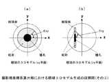
虹彩立体極座標画像生成部176は、撮影部15に備えるカメラで撮影した図5に示すような撮影画像(マスク処理済)から、図6及び図7に示すような、xyzの3次元座標系で表現した眼球の3Dモデルを生成し、図8(a)に示すような、横軸がこの3Dモデルのxy平面での角度θxy、縦軸がこの3Dモデルのzy平面での角度θzyに極座標変換した立体極座標画像を生成し、図8(b)に示すような、該立体極座標画像の瞳孔サイズを調整した正規化立体極座標画像を生成する部である。 The iris three-dimensional coordinate
ここで、虹彩立体極座標画像生成部176は、眼球の3Dモデルを生成するにあたって、図4に示す目の構造図に示すように、成人の場合の眼球直径は24mmであり、外部から見える虹彩直径(角膜直径)は12mmであり、これらの値は個人差は極めて少なく一定であるという参考文献2に記載のデータを用いている。そして、図7(b)に示す眼球の3Dモデルでは、虹彩の厚みは一定であるが、実際の虹彩は図4に示すように中央部分が膨らんだ形をしている。(参考文献2:日本人体解剖学 金子丑之助 1999年 「I視覚器 A.眼球」 参照) Here, when generating the 3D model of the eyeball, the iris stereoscopic polar coordinate
そして、虹彩立体極座標画像生成部176において、虹彩立体極座標画像の生成の指示を受けると、撮影極座標系算出部1761は、撮影極座標系の算出を開始する。 When the iris stereopolar coordinate
即ち、撮影極座標系算出部1761は、図5に示すように、二次元で視線が斜め上方の撮影画像(マスク処理済)内の内側境界及び外側境界を示す楕円の各中心位置を算出し、マスク画像内の内側境界及び外側境界を示す楕円において、内側境界の楕円の中心から放射線上で内側境界と外側境界の距離が最も大きい線分Aを抽出する。 That is, as shown in FIG. 5, the photographing polar coordinate
そして、撮影極座標系算出部1761は、上記線分Aを抽出すると、該線分Aと瞳孔を挟んで反対側の内側境界と外側境界との距離を示す線分Bを抽出する。 Then, when the line segment A is extracted, the photographing polar coordinate
更に、撮影極座標系算出部1761は、上記線分A及び線分Bを抽出すると、上記各中心位置と、該線分A及び線分Bの距離と、該線分A及び線分Bの傾きなどとを用いて、図6に示すような、登録希望者の視線方向を正面として撮影するための仮想のカメラ投影面を判定し、この仮想投影面に対し平行に対向すると仮定した瞳孔領域及び虹彩領域を中心としたxyz座標系列上の眼球の3Dモデルを生成する。ここで、図7(a)に眼球の3Dモデルのxy平面図を示し、図7(b)に眼球の3Dモデルのzy平面図を示す。 Furthermore, when the imaging polar coordinate
制御部12は、撮影極座標系算出部1761が眼球の3Dモデルを生成すると、虹彩立体極座標変換部1762に虹彩立体極座標変換を指示する。 When the imaging polar coordinate
虹彩立体極座標変換部1762は、眼球の3Dモデル上の瞳孔領域及び虹彩領域において、眼球の3Dモデルの原点からxy平面での角度θxyと、zy平面での角度θzyとにおける立体極座標(θxy、θzy)上の各画素値を算出し、横軸をθxy、縦軸をθzyで示す虹彩立体極座標画像を生成する部である。 The iris three-dimensional polar coordinate
即ち、虹彩立体極座標変換部1762は、虹彩立体極座標変換の指示を受けると、眼球の3Dモデルを用いて図8(a)に示すような虹彩立体極座標画像を生成する。 That is, upon receiving an instruction for iris solid polar coordinate conversion, the iris solid polar coordinate
制御部12は、虹彩立体極座標変換部1762が虹彩立体極座標画像を生成すると、瞳孔正規化処理部1763に瞳孔領域のサイズの正規化を指示する。 When the iris solid polar coordinate
瞳孔正規化処理部1763は、虹彩立体極座標画像上の瞳孔領域のサイズを予め設定した規定瞳孔領域サイズに正規化し、正規の虹彩領域の極座標画像を示す正規化虹彩立体極座標画像を生成する部である。 The pupil normalization processing unit 1863 is a unit that normalizes the size of the pupil region on the iris three-dimensional polar coordinate image to a preset prescribed pupil region size, and generates a normalized iris three-dimensional polar coordinate image indicating the polar coordinate image of the normal iris region. is there.
即ち、瞳孔正規化処理部1763は、瞳孔領域のサイズの正規化の指示を受けると、虹彩立体極座標画像の瞳孔領域のサイズを規定瞳孔領域サイズに正規化し、図8(b)に示すような正規化虹彩立体極座標画像を生成する。 In other words, upon receiving an instruction for normalizing the size of the pupil region, the pupil normalization processing unit 1863 normalizes the size of the pupil region of the iris stereoscopic polar coordinate image to the prescribed pupil region size, as shown in FIG. A normalized iris solid polar coordinate image is generated.
制御部12は、瞳孔正規化処理部1763が正規化虹彩立体極座標画像を生成すると、虹彩立体極座標コード生成部177に虹彩立体極座標コードの生成を指示する。 When the pupil
虹彩立体極座標コード生成部177は、図9に示すように、正規化虹彩立体極座標画像をM×Nの領域に区切り、各領域の特徴に基づいて正規化虹彩立体極座標画像をコード化する部である。 As shown in FIG. 9, the iris solid polar coordinate
ここで、虹彩立体極座標コード生成部177は、M×Nの各領域に対し図10に示すような方向性フィルタ及びガボールフィルタのいずれかを用いて、もしくは方向性フィルタ及びガボールフィルタの両フィルタを用いて、各領域の特徴を示すエッジ成分の方向性及び周波数を抽出し、これら方向性及び周波数をコード化した虹彩立体極座標コードを生成する。尚、正規化虹彩立体極座標画像のM×Nの領域の区分けにおいては、隣の領域同士が一部重なり合うような区分け方法を用いてもよい。 Here, the iris three-dimensional polar
また、虹彩立体極座標コード生成部177は、M×Nの各領域に対し2次元フーリエ変換及び2次元ウェーブレット変換のいずれかを行い、もしくは2次元フーリエ変換及び2次元ウェーブレット変換の両変換を行い、変換により得られた各領域の特徴量をコード化した虹彩立体極座標コードを生成してもよい。 The iris stereopolar
更に、虹彩立体極座標コード生成部177は、M×Nの各領域に対し、各領域と他の領域とをパターンマッチングを用いて比較し、マッチング結果に基づいて、各領域が他の領域の中のどの領域と類似しているのかを複数の領域の各識別情報を用いてコード化して虹彩立体極座標コードを生成してもよい。 Further, the iris three-dimensional polar
そして、虹彩立体極座標コード生成部177は、M×Nの各領域に図示しないメモリに予め設定した閾値面積以上のマスク領域を含む領域が存在すると、該領域に対し特徴抽出を行わず、該領域が虹彩情報の対象外になるようにマスクコードを生成するものとする。 Then, if there is a region including a mask region larger than a preset threshold area in a memory (not shown) in each M × N region, the iris solid polar
即ち、虹彩立体極座標コード生成部177は、虹彩立体極座標コードの生成の指示を受けると、正規化虹彩立体極座標画像をM×Nの領域に区切り、各領域の特徴を示すマスクコードを含む虹彩立体極座標コードを生成する。 In other words, upon receiving an instruction to generate an iris solid polar coordinate code, the iris solid polar coordinate
制御部12は、虹彩立体極座標コード生成部177が虹彩立体極座標コードが生成すると、この虹彩立体極座標コードと、一時記憶部16で保持する識別番号(ID番号)とを対応付けた登録生体情報を生体情報DB20に記憶する。 When the iris stereopolar coordinate
そして、制御部12は、登録生体情報を生体情報DB20に記憶すると、図示しないメモリで保持する制御プログラムを実行し、生体情報の登録が完了したことを通知する登録完了通知画面を表示部13に表示させると共に、登録処理を終了する。 Then, after storing the registered biometric information in the
認証装置30は、個人認証システムの利用者の本人認証を行うために、識別対象者が操作する装置であり、図2に示すように、ネットワーク40に接続されている通信部31と、装置全体を制御する制御部32と、表示部33と、入力部34と、撮影部35と、一時記憶部36と、生体情報生成部37と、照合判定部38とを備える。 The authentication device 30 is a device that is operated by a person to be identified in order to authenticate the user of the personal authentication system. As shown in FIG. 2, the
生体情報生成部37は、図1、図2に示す登録装置10の生体情報生成部17と同じ構成であり、瞳孔虹彩境界抽出部371と、虹彩領域判定部372と、フォーカス判定部373と、マスク処理部374と、マスク領域判定部375と、虹彩立体極座標画像生成部376と、虹彩立体極座標コード生成部377とを備える。 The biometric
虹彩立体極座標画像生成部376は、図2に示す登録装置10の虹彩立体極座標画像生成部176と同じ構成であり、撮影極座標系算出部3761と、虹彩立体極座標変換部3762と、瞳孔正規化処理部3763とを備える。 The iris solid polar coordinate
認証装置30は、図示しないセンサを備え、このセンサが識別対象者を検知すると、制御部32は、図示しないメモリの制御プログラムを実行し、識別対象者に識別情報(ID番号)を入力させるための入力指示画面を表示部33に備えるディスプレイに表示させる。 The authentication device 30 includes a sensor (not shown). When the sensor detects a person to be identified, the
入力部34は、タッチパネル、もしくはボタンから成り、識別対象者が表示部33に表示された入力指示画面を参照し、識別情報(ID番号)を入力するために用いられる。 The
制御部32は、入力部34を介して識別情報が入力されると、この識別情報を一時記憶部36に記憶すると共に、図示しない制御プログラムを実行し、識別対象者が撮影部35に備えるカメラを見つめるよう指示するための撮影指示画面を表示部33に表示させる。そして、制御部32は、撮影指示画面を表示部33に表示させると共に、撮影部35に撮影を指示する。 When the identification information is input via the
制御部32は、エラー回数をカウントすると、このエラー回数と図示しないメモリに予め設定された最大回数とを比較し、エラー回数が最大回数より小さいと、図示しないメモリの制御プログラムを実行し、識別対象者に目のリトライ撮影を指示するためのリトライ撮影通知画面を表示部33に表示させると共に、撮影部35に撮影を指示する。 When the number of errors is counted, the
また、制御部32は、エラー回数が最大回数であると、図示しないメモリの制御プログラムを実行し、識別対象者に生体情報の認証が不可であることを通知するための認証不可通知画面を表示部33に備えるディスプレイに表示させ、認証処理を中止する。 Further, when the number of errors is the maximum number, the
制御部32は、虹彩立体極座標コード生成部377で虹彩立体極座標コードが生成すると、照合判定部38へ照合判定を指示する。ここで、虹彩立体極座標コード生成部377は、登録装置10の虹彩立体極座標コード生成部177と同一構成及び機能を備えている。 When the iris solid polar coordinate
照合判定部38は、識別対象者から取得した虹彩立体極座標コードが生体情報DB20で保持する利用者の登録生体情報の登録立体極座標コードと一致するか否かを判定する部である。 The
即ち、照合判定部38は、照合判定の指示を受けると、一時記憶部36で保持する識別情報(ID番号)に基づいて生体情報DB20の登録生体情報を検索し、該当する登録生体情報の立体極座標コードと、生成した立体極座標コードとを照合して一致不一致を判定し、一致すると、照合一致と判定する。ここで、照合判定部38は、認証時の撮影における識別対象者の顔の傾き(目の傾き)と、登録時の撮影における登録希望者の顔の傾き(目の傾き)が異なることを考慮して、登録立体極座標コード及び立体極座標コードのいずれかをθxy方向にシフトさせながら両立体極座標コードが一致するか否かの判定を行う。 That is, when the
一方、照合判定部38は、登録生体情報の立体極座標コードと、立体極座標コードとが一致しないと、照合不一致と判定する。更に、照合判定部38は、識別対象者が入力した識別情報が生体情報DB20に存在しないと、照合不一致と判定する。 On the other hand, the
制御部32は、照合判定部38が照合一致と判定すると、図示しないメモリの制御プログラムを実行し、識別対象者に本人認証したことを通知するための本人認証通知画面を表示部33に表示させると共に、例えば図示しない電子ドアの施錠を解除し、認証処理を終了する。 When the
一方、制御部32は、照合判定部38が照合不一致と判定すると、図示しないメモリの制御プログラムを実行し、識別対象者に認証が不可であることを通知するための認証不可通知画面を表示部33に表示させると共に、認証処理を中止する。 On the other hand, when the
尚、その他の構成は、登録装置10の構成と同じである。 Other configurations are the same as those of the registration apparatus 10.
<実施例の動作>
次に、本発明の個人認証システムの実施例の動作について説明する。<Operation of Example>
Next, the operation of the embodiment of the personal authentication system of the present invention will be described.
まず、登録希望者をシステム利用者として登録する動作の説明を行う。図11に実施例の利用者登録処理の動作のフローチャートを示す。 First, an operation for registering a registration applicant as a system user will be described. FIG. 11 shows a flowchart of the operation of the user registration process of the embodiment.
登録装置10の図示しないセンサが登録希望者を検知すると、制御部12は、図示しないメモリの制御プログラムを実行し、登録希望者に個人の識別情報(ID番号)を入力させるための入力指示画面を表示部13に備えるディスプレイに表示させる。 When a sensor (not shown) of the registration apparatus 10 detects a person who wants to register, the
登録希望者が表示部13に表示された入力画面を参照し、入力部14に備えるタッチパネル、もしくはボタンを用いて識別情報(ID番号)を入力すると(ステップS101)、制御部12は、この識別情報を一時記憶部16に記憶すると共に、通信部11を介して生体情報DB20に識別情報に該当する登録生体情報が存在するか否かを検索する。 When the registration applicant refers to the input screen displayed on the
そして、識別情報に該当する登録生体情報が生体情報DB20に存在しないと(ステップS102)、制御部12は、図示しないメモリの制御プログラムを実行し、登録希望者が撮影部15に備えるカメラを見つめるよう指示するための撮影指示通知画面を表示部13に表示させると共に、撮影部15に撮影を指示する。 If the registered biometric information corresponding to the identification information does not exist in the biometric information DB 20 (step S102), the
一方、識別情報に該当する登録生体情報が存在すると、制御部12は、図示しないメモリの制御プログラムを実行し、登録希望者に生体情報が既に登録済であることを通知するための登録済通知画面を表示部13に表示させ、登録処理を中止する。 On the other hand, if there is registered biometric information corresponding to the identification information, the
撮影部15は、撮影指示を受けると、登録希望者をカメラで撮影し、その撮影画像を取得する(ステップS103)。 When receiving the shooting instruction, the
撮影部15が撮影画像を取得すると、制御部12は、この撮影画像を一時記憶部16に記憶すると共に、生体情報生成部17に生体情報の生成を指示する。 When the
そして、生体情報生成部17において、生体情報の生成の指示を受けると、瞳孔虹彩境界抽出部171は、瞳孔虹彩境界の抽出を開始する。 When the biological
瞳孔虹彩境界抽出部171は、一時記憶部16で保持する撮影画像上の瞳孔及び虹彩の境界(内側境界)と、虹彩及び強膜の境界(外側境界)となる各楕円を検索し、内側境界及び外側境界となる両楕円が存在すると、両楕円を抽出すると共に、瞳孔領域及び虹彩領域を抽出する(ステップS104)。 The pupil-iris
瞳孔虹彩境界抽出部171が内側境界及び外側境界を抽出すると、制御部12は、虹彩領域判定部172に虹彩領域の判定を指示する。 When the pupil iris
一方、瞳孔虹彩境界抽出部171が上記撮影画像上に内側境界及び外側境界となる両楕円が存在しないため、両境界を抽出できないと、制御部12は、虹彩情報生成エラーとして図示しないカウント部でエラー回数をカウントする。 On the other hand, if the pupil / iris
そして、制御部12は、エラー回数をカウントすると、このエラー回数と図示しないメモリに予め設定された最大回数とを比較し、エラー回数が最大回数より小さいと(ステップS105)、図示しないメモリの制御プログラムを実行し、登録希望者に目のリトライ撮影を指示するためのリトライ撮影通知画面を表示部13に表示させると共に、撮影部15に撮影を指示する。 Then, when the number of errors is counted, the
また、制御部12は、エラー回数が最大回数であると、図示しないメモリの制御プログラムを実行し、登録希望者に生体情報の登録が不可であることを通知するための登録不可通知画面を表示部13に備えるディスプレイに表示させ、登録処理を中止する。 In addition, when the number of errors is the maximum number, the
虹彩領域判定部172は、虹彩領域の判定の指示を受けると、抽出した虹彩領域の面積を算出し、虹彩領域の面積が図示しないメモリに予め設定された虹彩面積閾値以上であると(ステップS106)、虹彩領域を有効と判定する。 Upon receiving the iris region determination instruction, the iris
一方、虹彩領域判定部172は、虹彩領域の面積が虹彩面積閾値より小さいと、虹彩領域を無効と判定する。 On the other hand, if the area of the iris region is smaller than the iris area threshold, the iris
虹彩領域判定部172が虹彩領域を有効と判定すると、制御部12は、フォーカス判定部173にフォーカス判定を指示する。 When the iris
一方、虹彩領域判定部172が無効と判定すると、制御部12は、虹彩情報生成エラーとして図示しないカウント部でエラー回数をカウントする。そして、制御部12は、エラー回数をカウントすると、ステップS105と同じ動作を行う。 On the other hand, when the iris
フォーカス判定部173は、フォーカス判定の指示を受けると、虹彩領域のエッジ強度の平均が予め設定したエッジ強度閾値以上であると、フォーカスが合っていると判定する(ステップS107)。 When receiving the focus determination instruction, the
一方、フォーカス判定部173は、虹彩領域のエッジ強度の平均が予め設定したエッジ強度より小さいと、フォーカスが合っていないと判定する。 On the other hand, when the average edge intensity of the iris region is smaller than the preset edge intensity, the
フォーカス判定部173がフォーカスが合っていると判定すると、制御部12は、マスク処理部174にマスク処理を指示する。 When the
一方、フォーカス判定部173がフォーカスが合っていないと判定すると、制御部12は、虹彩情報生成エラーとして図示しないカウント部でエラー回数をカウントする。そして、制御部12は、エラー回数をカウントすると、ステップS105と同じ動作を行う。 On the other hand, when the
マスク処理部174は、マスク処理の指示を受けると、虹彩領域にある瞼部分、睫部分、照明などの映り込みなどにより閾値を越えた輝度の部分などをノイズとして虹彩情報の対象外になるよう設定するために、虹彩領域に対してマスク処理を行う(ステップS108)。 When the
マスク処理部174がマスク処理を行うと、制御部12は、マスク領域判定部175にマスク領域の判定を指示する。 When the
マスク領域判定部175は、マスク領域の判定の指示を受けると、虹彩領域内のマスク領域を抽出し、マスク領域が予め設定したマスク領域閾値以下であると(ステップS109)、虹彩領域を有効と判定する。 When receiving the mask region determination instruction, the mask
一方、マスク領域判定部175は、マスク領域が予め設定したマスク領域閾値より大きいと、虹彩領域を無効と判定する。 On the other hand, the mask
マスク領域判定部175が虹彩領域を有効と判定すると、制御部12は、虹彩立体極座標画像生成部176に虹彩立体極座標画像の生成を指示する。 When the mask
一方、マスク領域判定部175が虹彩領域を無効と判定すると、制御部12は、虹彩情報生成エラーとして図示しないカウント部でエラー回数をカウントする。そして、制御部12は、エラー回数をカウントすると、ステップS105と同じ動作を行う。 On the other hand, when the mask
そして、虹彩立体極座標画像生成部176において、虹彩立体極座標画像の生成の指示を受けると、撮影極座標系算出部1761は、撮影極座標系の算出を開始する。 When the iris stereopolar coordinate
撮影極座標系算出部1761は、図5に示すように、二次元で視線が斜め上方の撮影画像(マスク処理済)内の内側境界及び外側境界を示す楕円の各中心位置を算出し、マスク画像内の内側境界及び外側境界を示す楕円において、内側境界の楕円の中心から放射線上で内側境界と外側境界の距離が最も大きい線分Aを抽出する。 As shown in FIG. 5, the photographing polar coordinate
そして、撮影極座標系算出部1761は、上記線分Aを抽出すると、該線分Aと瞳孔を挟んで反対側の内側境界と外側境界との距離を示す線分Bを抽出する。 Then, when the line segment A is extracted, the photographing polar coordinate
更に、撮影極座標系算出部1761は、上記線分A及び線分Bを抽出すると、上記各中心位置と、該線分A及び線分Bの距離と、該線分A及び線分Bの傾きなどとを用いて、図6に示すような、登録希望者の視線方向を正面として撮影するための仮想のカメラ投影面を判定し、この仮想投影面に対し平行に対向すると仮定した瞳孔領域及び虹彩領域を中心としたxyz座標系列上の眼球の3Dモデルを生成する(ステップS110)。 Furthermore, when the imaging polar coordinate
撮影極座標系算出部1761が眼球の3Dモデルを生成すると、制御部12は、虹彩立体極座標変換部1762に虹彩立体極座標変換を指示する。 When the imaging polar coordinate
虹彩立体極座標変換部1762は、虹彩立体極座標変換の指示を受けると、眼球の3Dモデル上の瞳孔領域及び虹彩領域において、眼球の3Dモデルの原点からxy平面での角度θxyと、zy平面での角度θzyとにおける立体極座標(θxy、θzy)上の各画素値を算出し、横軸をθxy、縦軸をθzyで示す虹彩立体極座標画像を生成する(ステップS111)。 Upon receiving an instruction for iris solid polar coordinate conversion, the iris solid polar coordinate
虹彩立体極座標変換部1762が虹彩立体極座標画像を生成すると、制御部12は、瞳孔正規化処理部1763に瞳孔領域のサイズの正規化を指示する。 When the iris solid polar coordinate
瞳孔正規化処理部1763は、瞳孔領域のサイズの正規化の指示を受けると、虹彩立体極座標画像の瞳孔領域のサイズを規定瞳孔領域サイズに正規化し、図8(b)に示すような正規化虹彩立体極座標画像を生成する(ステップS112)。 Upon receiving an instruction for normalizing the size of the pupil region, the pupil normalization processing unit 1863 normalizes the size of the pupil region of the iris stereoscopic polar coordinate image to the prescribed pupil region size, and normalizes as shown in FIG. An iris three-dimensional polar coordinate image is generated (step S112).
瞳孔正規化処理部1763が正規化虹彩立体極座標画像を生成すると、制御部12は、虹彩立体極座標コード生成部177に虹彩立体極座標コードの生成を指示する。 When the pupil normalization processing unit 1863 generates a normalized iris solid polar coordinate image, the
虹彩立体極座標コード生成部177は、虹彩立体極座標コードの生成の指示を受けると、図9に示すように、正規化虹彩立体極座標画像をM×Nの領域に区切り、各領域に図示しないメモリに予め設定した閾値面積以上のマスク領域を含む領域が存在すると、該領域に対し特徴抽出を行わず、該領域が虹彩情報の対象外になるようにマスクコードを生成する。 Upon receiving an instruction to generate an iris solid polar coordinate code, the iris solid polar coordinate
そして、虹彩立体極座標コード生成部177は、図示しないメモリに予め設定した閾値面積より小さい、もしくはマスク領域を含まない領域に対し図10に示すような方向性フィルタを用いて各領域の特徴を示すエッジ成分の方向性及び周波数を抽出し、これら方向性及び周波数をコード化した虹彩立体極座標コードを生成する。これにより、虹彩立体極座標コード生成部177は、各領域の特徴を示すマスクコードを含む虹彩立体極座標コードを生成する(ステップS113)。 Then, the iris three-dimensional polar
制御部12は、虹彩立体極座標コード生成部177が虹彩立体極座標コードが生成すると、この虹彩立体極座標コードと、一時記憶部16で保持する識別番号(ID番号)とを対応付けた登録生体情報を生体情報DB20に記憶する(ステップS114)。 When the iris stereopolar coordinate
そして、制御部12は、登録生体情報を生体情報DB20に記憶すると、図示しないメモリで保持する制御プログラムを実行し、生体情報の登録が完了したことを通知する登録完了通知画面を表示部13に表示させると共に、登録処理を終了する。 Then, after storing the registered biometric information in the
次に、識別対象者をシステム利用者として本人認証する動作の説明を行う。図12に実施例の利用者認証処理の動作のフローチャートを示す。 Next, an operation for authenticating the identification target person as a system user will be described. FIG. 12 shows a flowchart of the operation of the user authentication process of the embodiment.
認証装置30の図示しないセンサが識別対象者を検知すると、制御部32は、図示しないメモリの制御プログラムを実行し、識別対象者に識別情報(ID番号)を入力させるための入力指示画面を表示部33に備えるディスプレイに表示させる。 When a sensor (not shown) of the authentication device 30 detects an identification target person, the
識別対象者が表示部33に備えるディスプレイに表示された入力指示画面を参照し、入力部34に備えるタッチパネル、もしくはボタンを用いて識別情報(ID番号)を入力すると(ステップS201)、制御部32は、この識別情報を一時記憶部36に記憶すると共に、図示しない制御プログラムを実行し、識別対象者が撮影部35に備えるカメラを見つめるよう指示するための撮影指示画面を表示部33に表示させる。そして、制御部32は、撮影指示画面を表示部33に表示させると共に、撮影部35に撮影を指示する。 When the identification target person inputs identification information (ID number) using the touch panel or button provided in the
利用者認証処理のステップS202、S203の動作は、利用者登録処理のステップS103、S104の動作と同じである。 The operations of steps S202 and S203 of the user authentication process are the same as the operations of steps S103 and S104 of the user registration process.
制御部32は、エラー回数をカウントすると、このエラー回数と図示しないメモリに予め設定された最大回数とを比較し、エラー回数が最大回数より小さいと(ステップS204)、図示しないメモリの制御プログラムを実行し、識別対象者に目のリトライ撮影を指示するためのリトライ撮影通知画面を表示部33に表示させると共に、撮影部35に撮影を指示する。 When the number of errors is counted, the
また、制御部32は、エラー回数が最大回数であると、図示しないメモリの制御プログラムを実行し、識別対象者に生体情報の認証が不可であることを通知するための認証不可通知画面を表示部33に備えるディスプレイに表示させ、認証処理を中止する。 Further, when the number of errors is the maximum number, the
利用者認証処理のステップS205〜S212の動作は、利用者登録処理のステップS106〜S113の動作と同じである。 The operations in steps S205 to S212 of the user authentication process are the same as those in steps S106 to S113 of the user registration process.
制御部32は、虹彩立体極座標コード生成部377で虹彩立体極座標コードが生成すると、照合判定部38へ照合判定を指示する。 When the iris solid polar coordinate
照合判定部38は、照合判定の指示を受けると、通信部31を介し一時記憶部36で保持する識別情報(ID番号)に基づいて生体情報DB20の登録生体情報を検索し、該当する登録生体情報の立体極座標コードと、生成した立体極座標コードとを照合して一致不一致を判定し、一致すると(ステップS213)、照合一致と判定する。ここで、照合判定部38は、認証時の撮影における識別対象者の顔の傾き(目の傾き)と、登録時の撮影における登録希望者の顔の傾き(目の傾き)が異なることを考慮して、登録立体極座標コード及び立体極座標コードのいずれかをθxy方向にシフトさせながら両立体極座標コードが一致するか否かの判定を行う。 Upon receipt of the collation determination instruction, the
一方、照合判定部38は、登録生体情報の立体極座標コードと、立体極座標コードとが一致しないと、照合不一致と判定する。更に、照合判定部38は、識別対象者が入力した識別情報が生体情報DB20に存在しないと、照合不一致と判定する。 On the other hand, the
制御部32は、照合判定部38が照合一致と判定すると、図示しないメモリの制御プログラムを実行し、識別対象者に本人認証したことを通知するための本人認証通知画面を表示部33に表示させると共に、例えば図示しない電子ドアの施錠を解除し、認証処理を終了する(ステップS214)。 When the
一方、制御部32は、照合判定部38が照合不一致と判定すると、図示しないメモリの制御プログラムを実行し、識別対象者に認証が不可であることを通知するための認証不可通知画面を表示部33に表示させると共に、認証処理を中止する。 On the other hand, when the
<実施例の効果>
従来は、顔向きや視線が正面でない場合において実際の眼球の3Dモデルに合わせた正規化を行っておらず撮影された二次元画像を単に二次元平面上で幾何学的に正規化していただけであった。そのため、従来技術で生成された虹彩コードは、登録側と照合側で顔向きや視線が異なる場合の認証精度が低下していた。実施例の個人認証システムによれば、二次元で視線が斜め上方の撮影画像(マスク処理済)から、登録希望者の視線方向を正面として撮影するための仮想のカメラ投影面を判定し、この仮想投影面に対し平行に対向すると仮定した瞳孔領域及び虹彩領域を中心としたxyz座標系列上の眼球の3Dモデルを生成するので、利用者の視線方向の影響を受けることなく利用者の虹彩の特徴を高精度で示す虹彩立体極座標コードを生成することができる。このような実際の眼球の3Dモデルに合わせて正規化した虹彩立体極座標コードを用いることにより、顔向きや視線が正面でない場合においても高い精度で照合することができる。また、登録画像と照合画像で目の回転方向のずれについてもθxy方向のシフトを行うことで迅速に対応することができる。<Effect of Example>
Conventionally, when the face orientation and line of sight are not in front, normalization according to the 3D model of the actual eyeball is not performed, and the captured 2D image is simply geometrically normalized on a 2D plane. there were. For this reason, the iris code generated by the conventional technique has a reduced authentication accuracy when the face direction and line of sight differ between the registration side and the verification side. According to the personal authentication system of the embodiment, a virtual camera projection plane for photographing with the gaze direction of a registration applicant as a front is determined from a photographed image (mask-processed) in which the gaze is diagonally upward in two dimensions. Since the 3D model of the eyeball on the xyz coordinate series centered on the pupil region and the iris region assumed to face the virtual projection plane in parallel is generated, the user's iris direction is not affected by the user's gaze direction. It is possible to generate an iris three-dimensional polar coordinate code indicating the feature with high accuracy. By using an iris solid polar coordinate code normalized according to such a 3D model of an actual eyeball, it is possible to perform collation with high accuracy even when the face direction or line of sight is not in front. Further, the shift in the rotation direction of the eyes between the registered image and the collation image can be quickly dealt with by shifting in the θxy direction.
尚、本実施例の個人認証システムの利用者としては、馬等の動物を含んでいてもよい。 In addition, as a user of the personal authentication system of a present Example, animals, such as a horse, may be included.
本実施例の個人認証システムでは、利用者の片方の目を撮影した撮影画像から虹彩立体極座標画像を生成して虹彩立体極座標コードを取得することを例に説明したが、利用者の両方の目を撮影した撮影画像から各虹彩立体極座標画像を生成して各虹彩立体極座標コードを取得し、両虹彩立体極座標コードを本人認証に用いてもよい。これにより、本実施例の個人認証システムの認証精度は向上する。 In the personal authentication system of the present embodiment, an example has been described in which an iris stereopolar coordinate image is generated from a captured image obtained by capturing one eye of a user and an iris stereopolar coordinate code is acquired. It is also possible to generate each iris stereopolar coordinate image from the captured image obtained by capturing the image, obtain each iris stereopolar coordinate code, and use both iris stereopolar coordinate codes for personal authentication. Thereby, the authentication accuracy of the personal authentication system of the present embodiment is improved.
上記構成では、生体情報DB20に利用者の両方の目の各虹彩立体極座標コードを記憶したが、これに限らず利用者の両方の目を撮影条件を異ならせて複数回撮影した各画像から生成した複数の両方の目の各虹彩立体極座標コードを登録生体情報として生体情報DB20に記憶してもよい。 In the above configuration, the iris stereopolar coordinate code of both eyes of the user is stored in the
そして、上記構成においては、利用者認証時に識別対象者から取得した両方の目の各虹彩立体極座標コードのいずれか一方と、生体情報DB20で保持する登録生体情報の1つの虹彩立体極座標コードとが一致すると、利用者本人であると認証してもよい。 And in the said structure, either one of each iris stereopolar coordinate code of both eyes acquired from the identification subject at the time of user authentication and one iris stereopolar code of the registration biometric information hold | maintained by biometric information DB20 are the ones. If they match, the user may be authenticated.
また、上記構成においては、利用者認証時に識別対象者から取得した両方の目の各虹彩立体極座標コードと一致する登録生体情報の虹彩立体極座標コードが生体情報DB20で保持されていると、利用者本人であると認証してもよい。 Further, in the above configuration, when the iris stereopolar coordinate code of the registered biometric information that matches the iris stereopolar coordinate code of both eyes acquired from the identification target person at the time of user authentication is held in the
更に、上記構成においては、利用者認証時に識別対象者から取得した両方の目及び片方の目のいずれかの虹彩立体極座標コードと一致する登録生体情報の虹彩立体極座標コードが予め設定した閾値以上の割合で生体情報DB20で保持されていると、利用者本人であると認証してもよい。 Furthermore, in the above configuration, the iris stereopolar coordinate code of the registered biometric information that matches the iris stereopolar code of either eye or one eye acquired from the identification target person at the time of user authentication is equal to or greater than a preset threshold value. If the
そして、本実施例の個人認証システムでは、内側境界及び外側境界の抽出として瞳孔領域及び虹彩領域が楕円であることを例に説明したが、これに限らず、外形が凹凸の連続する形状を有する「自由閉曲線」の虹彩にも適用することができる。 In the personal authentication system of the present embodiment, the example has been described in which the pupil region and the iris region are ellipses as the extraction of the inner boundary and the outer boundary. However, the shape is not limited to this, and the outer shape has a continuous shape of unevenness. It can also be applied to "free closed curve" irises.
また、本実施例の個人認証システムでは、認証装置30の入力部34から識別情報(ID番号)を入力する構成にしたが、識別情報を入力せず、取得した識別対象者の虹彩立体極座標コードと生体情報DB20で保持する登録生体情報の虹彩立体極座標コードとを照合して識別対象者が利用者であるか否かを判定するという構成にしてもよい。 Further, in the personal authentication system of the present embodiment, the identification information (ID number) is input from the
更に、本実施例の個人認証システムでは、登録装置10と認証装置30とを備える構成にしたが、登録装置10及び認証装置30を1つの装置(端末)にまとめた登録認証装置を備える構成にしてもよい。 Furthermore, in the personal authentication system of the present embodiment, the configuration includes the registration device 10 and the authentication device 30, but the configuration includes a registration authentication device in which the registration device 10 and the authentication device 30 are combined into one device (terminal). May be.
上記構成において、登録認証装置は、生体情報DB20を登録認証装置内に備えてもよい。これにより、登録認証装置のみを用いて、利用者登録及び利用者認証を行うことができる。 In the above configuration, the registration authentication device may include the
そして、上記構成の登録認証装置は、登録認証装置内の生体情報DB20に利用者一人の登録生体情報を記憶する、例えばPDA(Personal Digital Assistants)及び携帯電話などのパーソナル端末であってもよい。The registration authentication device of the above configuration stores the registered biometric information alone user toBIOLOGICAL information DB20in the registration authentication device may be a personal terminal such as PDA (Personal Digital Assistants) and mobile phones .
前記した実施例では、本発明の実施例の個人認証システムを電子ドアの開錠に使用する場合を例に説明したが、これに限る必要はなく、空港ゲートでの本人認証、端末へのログインシステムなどに用いてもよい。 In the above-described embodiment, the case where the personal authentication system of the embodiment of the present invention is used for unlocking the electronic door has been described as an example. However, the present invention is not limited to this, and personal authentication at the airport gate, login to the terminal You may use for a system etc.
10 登録装置
11 通信部
12 制御部
13 表示部
14 入力部
15 撮影部
16 一時記憶部
17 生体情報生成部
171 瞳孔虹彩境界抽出部
172 虹彩領域判定部
173 フォーカス判定部
174 マスク処理部
175 マスク領域判定部
176 虹彩立体極座標画像生成部
1761 撮影極座標系算出部
1762 虹彩立体極座標変換部
1763 瞳孔正規化処理部
177 虹彩立体極座標コード生成部
20 生体情報データベース(DB)
30 認証装置
31 通信部
32 制御部
33 表示部
34 入力部
35 撮影部
36 一時記憶部
37 生体情報生成部
371 瞳孔虹彩境界抽出部
372 虹彩領域判定部
373 フォーカス判定部
374 マスク処理部
375 マスク領域判定部
376 虹彩立体極座標画像生成部
3761 撮影極座標系算出部
3762 虹彩立体極座標変換部
3763 瞳孔正規化処理部
377 虹彩立体極座標コード生成部
38 照合判定部
40 ネットワークDESCRIPTION OF SYMBOLS 10
DESCRIPTION OF SYMBOLS 30
Claims (1)
Translated fromJapanese前記抽出した瞳孔領域及び虹彩領域と該各領域の中心に基づいて前記虹彩を正面とするXY座標平面を算出し、かつ該平面に対し直交する線分Zを視線方向とする仮想のカメラ投影面を判定する視線方向算出手段と、
前記カメラ投影面から前記虹彩を正面とする三次元モデルを生成する三次元モデル生成手段と、
前記三次元モデルに対し極座変換を行い三次元極座標画像を生成する極座標変換部と、
前記生成した三次元極座標画像を複数の領域に区切り、各領域毎の特徴を抽出してコード化した三次元極座標画像コードを生成する三次元極座標画像コード化手段と、
を含むことを特徴とする個人認証システム。In a personal authentication system comprising imaging means for imaging an eye including a user's iris, and pupil iris area extracting means for extracting a pupil area and an iris area from the captured image,
A virtual camera projection plane that calculates an XY coordinate plane with the iris in front based on the extracted pupil region and iris region and the center of each region, and that has a line segment Z orthogonal to the plane as a viewing direction Gaze direction calculating means for determining
Three-dimensional model generation means for generating a three-dimensional model with the iris in front from the camera projection plane;
A polar coordinate conversion unit for performing a polar conversion on the three-dimensional model to generate a three-dimensional polar coordinate image;
A three-dimensional polar coordinate image encoding means for generating a three-dimensional polar coordinate image code obtained by dividing the generated three-dimensional polar coordinate image into a plurality of regions and extracting and encoding features for each region;
A personal authentication system comprising:
Priority Applications (6)
| Application Number | Priority Date | Filing Date | Title |
|---|---|---|---|
| JP2006268860AJP4650386B2 (en) | 2006-09-29 | 2006-09-29 | Personal authentication system and personal authentication method |
| US12/443,280US8170295B2 (en) | 2006-09-29 | 2007-08-03 | Personal authentication system and personal authentication method |
| KR1020097006992AKR20090074185A (en) | 2006-09-29 | 2007-08-03 | Personal Authentication System and Personal Authentication Method |
| PCT/JP2007/065292WO2008041414A1 (en) | 2006-09-29 | 2007-08-03 | Personal authentication system and personal authentication method |
| CNA2007800351294ACN101517615A (en) | 2006-09-29 | 2007-08-03 | Personal authentication system and personal authentication method |
| EP07791965AEP2081152A1 (en) | 2006-09-29 | 2007-08-03 | Personal authentication system and personal authentication method |
Applications Claiming Priority (1)
| Application Number | Priority Date | Filing Date | Title |
|---|---|---|---|
| JP2006268860AJP4650386B2 (en) | 2006-09-29 | 2006-09-29 | Personal authentication system and personal authentication method |
Related Child Applications (1)
| Application Number | Title | Priority Date | Filing Date |
|---|---|---|---|
| JP2010229459ADivisionJP5187372B2 (en) | 2010-10-12 | 2010-10-12 | Personal authentication system and personal authentication method |
Publications (2)
| Publication Number | Publication Date |
|---|---|
| JP2008090482A JP2008090482A (en) | 2008-04-17 |
| JP4650386B2true JP4650386B2 (en) | 2011-03-16 |
Family
ID=39268279
Family Applications (1)
| Application Number | Title | Priority Date | Filing Date |
|---|---|---|---|
| JP2006268860AExpired - Fee RelatedJP4650386B2 (en) | 2006-09-29 | 2006-09-29 | Personal authentication system and personal authentication method |
Country Status (6)
| Country | Link |
|---|---|
| US (1) | US8170295B2 (en) |
| EP (1) | EP2081152A1 (en) |
| JP (1) | JP4650386B2 (en) |
| KR (1) | KR20090074185A (en) |
| CN (1) | CN101517615A (en) |
| WO (1) | WO2008041414A1 (en) |
Families Citing this family (84)
| Publication number | Priority date | Publication date | Assignee | Title |
|---|---|---|---|---|
| US8260008B2 (en) | 2005-11-11 | 2012-09-04 | Eyelock, Inc. | Methods for performing biometric recognition of a human eye and corroboration of same |
| JP4924603B2 (en)* | 2006-03-01 | 2012-04-25 | 日本電気株式会社 | Face authentication device, face authentication method and program |
| US8364646B2 (en) | 2006-03-03 | 2013-01-29 | Eyelock, Inc. | Scalable searching of biometric databases using dynamic selection of data subsets |
| US8604901B2 (en) | 2006-06-27 | 2013-12-10 | Eyelock, Inc. | Ensuring the provenance of passengers at a transportation facility |
| US8965063B2 (en) | 2006-09-22 | 2015-02-24 | Eyelock, Inc. | Compact biometric acquisition system and method |
| WO2008042879A1 (en) | 2006-10-02 | 2008-04-10 | Global Rainmakers, Inc. | Fraud resistant biometric financial transaction system and method |
| US8953849B2 (en) | 2007-04-19 | 2015-02-10 | Eyelock, Inc. | Method and system for biometric recognition |
| WO2008131201A1 (en) | 2007-04-19 | 2008-10-30 | Global Rainmakers, Inc. | Method and system for biometric recognition |
| US20120239458A9 (en)* | 2007-05-18 | 2012-09-20 | Global Rainmakers, Inc. | Measuring Effectiveness of Advertisements and Linking Certain Consumer Activities Including Purchases to Other Activities of the Consumer |
| US8212870B2 (en) | 2007-09-01 | 2012-07-03 | Hanna Keith J | Mirror system and method for acquiring biometric data |
| WO2009029757A1 (en) | 2007-09-01 | 2009-03-05 | Global Rainmakers, Inc. | System and method for iris data acquisition for biometric identification |
| US9117119B2 (en) | 2007-09-01 | 2015-08-25 | Eyelock, Inc. | Mobile identity platform |
| US9036871B2 (en) | 2007-09-01 | 2015-05-19 | Eyelock, Inc. | Mobility identity platform |
| US9002073B2 (en) | 2007-09-01 | 2015-04-07 | Eyelock, Inc. | Mobile identity platform |
| WO2009158662A2 (en) | 2008-06-26 | 2009-12-30 | Global Rainmakers, Inc. | Method of reducing visibility of illimination while acquiring high quality imagery |
| JP2010033305A (en)* | 2008-07-29 | 2010-02-12 | Hitachi Ltd | Image information processing method and device |
| EP3269296A1 (en)* | 2008-12-01 | 2018-01-17 | Perfect Vision Technology (HK) Ltd. | Methods and devices for refractive correction of eyes |
| US9277863B2 (en) | 2008-12-01 | 2016-03-08 | Perfect Vision Technology (Hk) Ltd. | Methods and systems for automated measurement of the eyes and delivering of sunglasses and eyeglasses |
| US9649032B2 (en) | 2008-12-01 | 2017-05-16 | Perfect Vision Technology (Hk) Ltd. | Systems and methods for remote measurement of the eyes and delivering of sunglasses and eyeglasses |
| JP5365214B2 (en)* | 2009-01-22 | 2013-12-11 | 日本電気株式会社 | Image processing apparatus, biometric authentication apparatus, image processing method, and program |
| JP5310130B2 (en)* | 2009-03-11 | 2013-10-09 | オムロン株式会社 | Display method of recognition result by three-dimensional visual sensor and three-dimensional visual sensor |
| JP2010210585A (en)* | 2009-03-12 | 2010-09-24 | Omron Corp | Model display method in three-dimensional visual sensor, and three-dimensional visual sensor |
| JP5245938B2 (en)* | 2009-03-12 | 2013-07-24 | オムロン株式会社 | 3D recognition result display method and 3D visual sensor |
| JP5316118B2 (en)* | 2009-03-12 | 2013-10-16 | オムロン株式会社 | 3D visual sensor |
| JP5714232B2 (en)* | 2009-03-12 | 2015-05-07 | オムロン株式会社 | Calibration apparatus and method for confirming accuracy of parameters for three-dimensional measurement |
| JP5282614B2 (en)* | 2009-03-13 | 2013-09-04 | オムロン株式会社 | Model data registration method and visual sensor for visual recognition processing |
| US8195044B2 (en) | 2009-03-30 | 2012-06-05 | Eyelock Inc. | Biometric camera mount system |
| CN102483845B (en)* | 2009-09-11 | 2018-09-04 | 富士通株式会社 | Organism authentication apparatus, biometrics authentication system and biometric authentication method |
| US20110119141A1 (en)* | 2009-11-16 | 2011-05-19 | Hoyos Corporation | Siccolla Identity Verification Architecture and Tool |
| WO2011065952A1 (en)* | 2009-11-30 | 2011-06-03 | Hewlett-Packard Development Company, L.P. | Face recognition apparatus and methods |
| FR2953616B1 (en) | 2009-12-08 | 2011-12-09 | Thales Sa | METHOD FOR CORRECTING THE POSITION OF EYES IN AN IMAGE |
| KR20160042461A (en)* | 2010-05-28 | 2016-04-19 | 퀄컴 인코포레이티드 | Dataset creation for tracking targets with dynamically changing portions |
| DE102010054168B4 (en)* | 2010-12-12 | 2017-09-07 | Chronos Vision Gmbh | Method, device and program for determining the torsional component of the eye position |
| CN102107179B (en)* | 2010-12-14 | 2013-07-24 | 浙江工业大学 | Method for controlling single-layer leather gluing based on binocular vision |
| US10043229B2 (en) | 2011-01-26 | 2018-08-07 | Eyelock Llc | Method for confirming the identity of an individual while shielding that individual's personal data |
| RU2589859C2 (en) | 2011-02-17 | 2016-07-10 | АЙЛОК ЭлЭлСи | Efficient method and system for obtaining image data of scene and iris image using one sensor |
| WO2012145405A2 (en) | 2011-04-19 | 2012-10-26 | Eyelock Inc. | Biometric chain of provenance |
| EP2748768A4 (en) | 2011-08-22 | 2016-05-11 | Eyelock Llc | Systems and methods for capturing artifact free images |
| US9058479B2 (en)* | 2012-04-17 | 2015-06-16 | International Business Machines Corporation | Pass-pattern authentication for computer-based security |
| CN103902029B (en)* | 2012-12-26 | 2018-03-27 | 腾讯数码(天津)有限公司 | A kind of mobile terminal and its unlocking method |
| US9495526B2 (en) | 2013-03-15 | 2016-11-15 | Eyelock Llc | Efficient prevention of fraud |
| US20140310801A1 (en)* | 2013-04-11 | 2014-10-16 | Nokia Corporation | Method and Apparatus for Performing Authentication |
| WO2015102704A2 (en)* | 2013-10-08 | 2015-07-09 | Sri International | Iris biometric recognition module and access control assembly |
| JP2015088098A (en)* | 2013-11-01 | 2015-05-07 | 株式会社ソニー・コンピュータエンタテインメント | Information processor and information processing method |
| EP3087533A4 (en) | 2013-12-23 | 2017-09-20 | Eyelock Llc | Methods and apparatus for power-efficient iris recognition |
| EP3092601A4 (en) | 2014-01-06 | 2017-11-29 | Eyelock Llc | Methods and apparatus for repetitive iris recognition |
| CN104809424B (en)* | 2014-01-23 | 2020-11-10 | 北京七鑫易维信息技术有限公司 | Method for realizing sight tracking based on iris characteristics |
| CN103955881B (en)* | 2014-04-18 | 2017-06-16 | 中国科学院信息工程研究所 | A kind of guard method of image biological feature and device and information recovering method |
| US9934436B2 (en)* | 2014-05-30 | 2018-04-03 | Leidos Innovations Technology, Inc. | System and method for 3D iris recognition |
| WO2016040836A1 (en) | 2014-09-12 | 2016-03-17 | Eyelock Llc | Methods and apparatus for directing the gaze of a user in an iris recognition system |
| CN105591745A (en)* | 2014-11-07 | 2016-05-18 | 中国银联股份有限公司 | Method and system for performing identity authentication on user using third-party application |
| CN105678137A (en)* | 2014-11-19 | 2016-06-15 | 中兴通讯股份有限公司 | Method and device for identity recognition |
| WO2016081609A1 (en) | 2014-11-19 | 2016-05-26 | Eyelock Llc | Model-based prediction of an optimal convenience metric for authorizing transactions |
| US9674396B1 (en) | 2014-12-17 | 2017-06-06 | Evernote Corporation | Matrix capture of large scanned documents |
| US10074011B2 (en) | 2015-01-20 | 2018-09-11 | Eyelock Llc | Lens system for high quality visible image acquisition and infra-red iris image acquisition |
| CA3017401C (en) | 2015-03-12 | 2019-12-31 | Eyelock Llc | Methods and systems for managing network activity using biometrics |
| CN106034029A (en) | 2015-03-20 | 2016-10-19 | 阿里巴巴集团控股有限公司 | Verification method and apparatus based on image verification codes |
| JP6503856B2 (en)* | 2015-04-10 | 2019-04-24 | 株式会社豊田中央研究所 | Iris pattern comparison device and program |
| US9495590B1 (en)* | 2015-04-23 | 2016-11-15 | Global Bionic Optics, Ltd. | Extended depth-of-field biometric system |
| CN105049061B (en)* | 2015-04-28 | 2018-06-01 | 北京邮电大学 | Based on the higher-dimension base stage code decoder and polarization code coding method calculated in advance |
| US9811729B2 (en)* | 2015-05-12 | 2017-11-07 | Ut-Battelle, Llc | Iris recognition via plenoptic imaging |
| KR102334209B1 (en)* | 2015-06-15 | 2021-12-02 | 삼성전자주식회사 | Method for authenticating user and electronic device supporting the same |
| JP6885935B2 (en)* | 2015-10-16 | 2021-06-16 | マジック リープ, インコーポレイテッドMagic Leap,Inc. | Eye pose identification using eye features |
| EP3394594A4 (en) | 2015-12-21 | 2019-08-14 | Eyelock Llc | Reflected optic camera module for iris recognition in a computing device |
| JP2017162233A (en)* | 2016-03-10 | 2017-09-14 | アルプス電気株式会社 | Visual line detection device and visual line detection method |
| CN105913487B (en)* | 2016-04-09 | 2018-07-06 | 北京航空航天大学 | One kind is based on the matched direction of visual lines computational methods of iris edge analysis in eye image |
| US10444539B2 (en) | 2016-05-11 | 2019-10-15 | Perect Vision Technology (Hk) Ltd. | Methods and systems for determining refractive corrections of human eyes for eyeglasses |
| EP3458997A2 (en) | 2016-05-18 | 2019-03-27 | Eyelock, LLC | Iris recognition methods and systems based on an iris stochastic texture model |
| RU2628201C1 (en)* | 2016-07-07 | 2017-08-15 | Самсунг Электроникс Ко., Лтд. | Method of adaptive quantization for encoding iris image |
| WO2018008934A2 (en)* | 2016-07-07 | 2018-01-11 | Samsung Electronics Co., Ltd. | Adaptive quantization method for iris image encoding |
| CN107066079A (en) | 2016-11-29 | 2017-08-18 | 阿里巴巴集团控股有限公司 | Service implementation method and device based on virtual reality scenario |
| KR102369412B1 (en)* | 2017-02-02 | 2022-03-03 | 삼성전자주식회사 | Device and method to recognize iris |
| US10534969B2 (en) | 2017-02-24 | 2020-01-14 | Eyelock Llc | Systems and methods for providing illumination for iris biometric acquisition |
| CN107122642A (en)* | 2017-03-15 | 2017-09-01 | 阿里巴巴集团控股有限公司 | Identity identifying method and device based on reality environment |
| JPWO2018220963A1 (en)* | 2017-06-02 | 2020-04-02 | ソニー株式会社 | Information processing apparatus, information processing method, and program |
| US11017226B2 (en) | 2017-08-30 | 2021-05-25 | Nec Corporation | Image processing system, image processing method, and storage medium |
| CA3015802C (en) | 2017-08-31 | 2021-06-22 | Eyelock, Llc | Systems and methods of biometric acquistion using positive optical distortion |
| WO2019103520A1 (en)* | 2017-11-24 | 2019-05-31 | 삼성전자 주식회사 | Device and method for user authentication on basis of iris recognition |
| RU2670798C9 (en) | 2017-11-24 | 2018-11-26 | Самсунг Электроникс Ко., Лтд. | Method of iris authentication of user and device therefor |
| EP3719743A4 (en) | 2017-11-29 | 2021-08-11 | Nec Corporation | Information processing system, information processing method, and storage medium |
| US11042628B2 (en) | 2018-02-15 | 2021-06-22 | Verifone, Inc. | Systems and methods for authentication code entry using mobile electronic devices |
| JP2019152929A (en)* | 2018-02-28 | 2019-09-12 | パナソニックIpマネジメント株式会社 | Authentication device and authentication method |
| JP7211492B2 (en)* | 2019-03-29 | 2023-01-24 | 日本電気株式会社 | Imaging system and imaging method |
| EP4010876A4 (en) | 2019-08-09 | 2022-08-24 | Nec Corporation | Information processing system, information processing method, and storage medium |
Family Cites Families (5)
| Publication number | Priority date | Publication date | Assignee | Title |
|---|---|---|---|---|
| US5291560A (en)* | 1991-07-15 | 1994-03-01 | Iri Scan Incorporated | Biometric personal identification system based on iris analysis |
| JPH10262952A (en) | 1997-03-28 | 1998-10-06 | Oki Electric Ind Co Ltd | Pupil detector |
| JP2004185386A (en)* | 2002-12-04 | 2004-07-02 | Matsushita Electric Ind Co Ltd | Image collation device |
| JP2005334402A (en) | 2004-05-28 | 2005-12-08 | Sanyo Electric Co Ltd | Authentication method and authentication apparatus |
| JP4664147B2 (en)* | 2005-07-29 | 2011-04-06 | 株式会社山武 | Iris authentication device |
- 2006
- 2006-09-29JPJP2006268860Apatent/JP4650386B2/ennot_activeExpired - Fee Related
- 2007
- 2007-08-03USUS12/443,280patent/US8170295B2/ennot_activeExpired - Fee Related
- 2007-08-03EPEP07791965Apatent/EP2081152A1/ennot_activeWithdrawn
- 2007-08-03CNCNA2007800351294Apatent/CN101517615A/enactivePending
- 2007-08-03WOPCT/JP2007/065292patent/WO2008041414A1/enactiveApplication Filing
- 2007-08-03KRKR1020097006992Apatent/KR20090074185A/ennot_activeWithdrawn
Also Published As
| Publication number | Publication date |
|---|---|
| US8170295B2 (en) | 2012-05-01 |
| JP2008090482A (en) | 2008-04-17 |
| WO2008041414A1 (en) | 2008-04-10 |
| KR20090074185A (en) | 2009-07-06 |
| EP2081152A1 (en) | 2009-07-22 |
| US20100074477A1 (en) | 2010-03-25 |
| CN101517615A (en) | 2009-08-26 |
Similar Documents
| Publication | Publication Date | Title |
|---|---|---|
| JP4650386B2 (en) | Personal authentication system and personal authentication method | |
| KR100954640B1 (en) | Personal authentication method and personal authentication device | |
| US10205883B2 (en) | Display control method, terminal device, and storage medium | |
| KR102587193B1 (en) | System and method for performing fingerprint-based user authentication using images captured using a mobile device | |
| JP5605854B2 (en) | Authentication system and authentication apparatus using biometric information | |
| WO2007004498A1 (en) | Iris authentication device, iris authentication method, and iris authentication program | |
| US20110142297A1 (en) | Camera Angle Compensation in Iris Identification | |
| WO2021036436A1 (en) | Facial recognition method and apparatus | |
| JP2007249586A (en) | Authentication device, authentication method, authentication program, and computer-readable recording medium | |
| JP3586456B2 (en) | Personal authentication method and personal authentication device | |
| JP2017533516A (en) | Fingerprint authentication using stitching and cutting | |
| JP2008090483A (en) | Personal identification system and personal identification method | |
| JP5796523B2 (en) | Biological information acquisition apparatus, biological information acquisition method, and biological information acquisition control program | |
| JP2009015518A (en) | Eye image photographing device and authentication device | |
| CN105631285A (en) | Biological feature identity recognition method and apparatus | |
| JP5187372B2 (en) | Personal authentication system and personal authentication method | |
| KR102333453B1 (en) | Smartphone-based identity verification method using fingerprints and facial images | |
| JP2008041034A (en) | Authentication device, registration device, registration authentication device, authentication method, registration method, authentication program, and registration program | |
| JP3991042B2 (en) | Personal authentication method and personal authentication device | |
| CN113316781A (en) | Authentication system, authentication device, and authentication method | |
| JP5768441B2 (en) | Biological information acquisition apparatus, biological information acquisition method, and biological information acquisition program | |
| JP2005334403A (en) | Method and device for authentication | |
| KR100608307B1 (en) | Facial recognition method and system | |
| JPWO2008081527A1 (en) | Authentication device, portable terminal device, and authentication method | |
| KR20110023407A (en) | Face recognition method robust to face change |
Legal Events
| Date | Code | Title | Description |
|---|---|---|---|
| A621 | Written request for application examination | Free format text:JAPANESE INTERMEDIATE CODE: A621 Effective date:20090417 | |
| A131 | Notification of reasons for refusal | Free format text:JAPANESE INTERMEDIATE CODE: A131 Effective date:20100413 | |
| A521 | Request for written amendment filed | Free format text:JAPANESE INTERMEDIATE CODE: A523 Effective date:20100614 | |
| A02 | Decision of refusal | Free format text:JAPANESE INTERMEDIATE CODE: A02 Effective date:20100713 | |
| A521 | Request for written amendment filed | Free format text:JAPANESE INTERMEDIATE CODE: A523 Effective date:20101012 | |
| A911 | Transfer to examiner for re-examination before appeal (zenchi) | Free format text:JAPANESE INTERMEDIATE CODE: A911 Effective date:20101026 | |
| TRDD | Decision of grant or rejection written | ||
| A01 | Written decision to grant a patent or to grant a registration (utility model) | Free format text:JAPANESE INTERMEDIATE CODE: A01 Effective date:20101116 | |
| A01 | Written decision to grant a patent or to grant a registration (utility model) | Free format text:JAPANESE INTERMEDIATE CODE: A01 | |
| A61 | First payment of annual fees (during grant procedure) | Free format text:JAPANESE INTERMEDIATE CODE: A61 Effective date:20101129 | |
| R150 | Certificate of patent or registration of utility model | Free format text:JAPANESE INTERMEDIATE CODE: R150 | |
| FPAY | Renewal fee payment (event date is renewal date of database) | Free format text:PAYMENT UNTIL: 20131224 Year of fee payment:3 | |
| FPAY | Renewal fee payment (event date is renewal date of database) | Free format text:PAYMENT UNTIL: 20131224 Year of fee payment:3 | |
| S531 | Written request for registration of change of domicile | Free format text:JAPANESE INTERMEDIATE CODE: R313531 | |
| FPAY | Renewal fee payment (event date is renewal date of database) | Free format text:PAYMENT UNTIL: 20131224 Year of fee payment:3 | |
| R350 | Written notification of registration of transfer | Free format text:JAPANESE INTERMEDIATE CODE: R350 | |
| LAPS | Cancellation because of no payment of annual fees |