JP4649035B2 - Eye characteristics measuring device - Google Patents
Eye characteristics measuring deviceDownload PDFInfo
- Publication number
- JP4649035B2 JP4649035B2JP2000318534AJP2000318534AJP4649035B2JP 4649035 B2JP4649035 B2JP 4649035B2JP 2000318534 AJP2000318534 AJP 2000318534AJP 2000318534 AJP2000318534 AJP 2000318534AJP 4649035 B2JP4649035 B2JP 4649035B2
- Authority
- JP
- Japan
- Prior art keywords
- eye
- light
- unit
- coordinate
- light receiving
- Prior art date
- Legal status (The legal status is an assumption and is not a legal conclusion. Google has not performed a legal analysis and makes no representation as to the accuracy of the status listed.)
- Expired - Fee Related
Links
Images


Classifications
- A—HUMAN NECESSITIES
- A61—MEDICAL OR VETERINARY SCIENCE; HYGIENE
- A61B—DIAGNOSIS; SURGERY; IDENTIFICATION
- A61B3/00—Apparatus for testing the eyes; Instruments for examining the eyes
- A61B3/10—Objective types, i.e. instruments for examining the eyes independent of the patients' perceptions or reactions
- A61B3/1015—Objective types, i.e. instruments for examining the eyes independent of the patients' perceptions or reactions for wavefront analysis
- A—HUMAN NECESSITIES
- A61—MEDICAL OR VETERINARY SCIENCE; HYGIENE
- A61B—DIAGNOSIS; SURGERY; IDENTIFICATION
- A61B3/00—Apparatus for testing the eyes; Instruments for examining the eyes
- A61B3/10—Objective types, i.e. instruments for examining the eyes independent of the patients' perceptions or reactions
- A61B3/107—Objective types, i.e. instruments for examining the eyes independent of the patients' perceptions or reactions for determining the shape or measuring the curvature of the cornea
- A—HUMAN NECESSITIES
- A61—MEDICAL OR VETERINARY SCIENCE; HYGIENE
- A61B—DIAGNOSIS; SURGERY; IDENTIFICATION
- A61B3/00—Apparatus for testing the eyes; Instruments for examining the eyes
- A61B3/10—Objective types, i.e. instruments for examining the eyes independent of the patients' perceptions or reactions
- A61B3/14—Arrangements specially adapted for eye photography
- A61B3/15—Arrangements specially adapted for eye photography with means for aligning, spacing or blocking spurious reflection ; with means for relaxing
- A61B3/152—Arrangements specially adapted for eye photography with means for aligning, spacing or blocking spurious reflection ; with means for relaxing for aligning
- A—HUMAN NECESSITIES
- A61—MEDICAL OR VETERINARY SCIENCE; HYGIENE
- A61B—DIAGNOSIS; SURGERY; IDENTIFICATION
- A61B3/00—Apparatus for testing the eyes; Instruments for examining the eyes
- A61B3/10—Objective types, i.e. instruments for examining the eyes independent of the patients' perceptions or reactions
- A61B3/113—Objective types, i.e. instruments for examining the eyes independent of the patients' perceptions or reactions for determining or recording eye movement
Landscapes
- Life Sciences & Earth Sciences (AREA)
- Health & Medical Sciences (AREA)
- Medical Informatics (AREA)
- Biophysics (AREA)
- Ophthalmology & Optometry (AREA)
- Engineering & Computer Science (AREA)
- Biomedical Technology (AREA)
- Heart & Thoracic Surgery (AREA)
- Physics & Mathematics (AREA)
- Molecular Biology (AREA)
- Surgery (AREA)
- Animal Behavior & Ethology (AREA)
- General Health & Medical Sciences (AREA)
- Public Health (AREA)
- Veterinary Medicine (AREA)
- Eye Examination Apparatus (AREA)
Description
Translated fromJapanese【0001】
【発明の属する技術分野】
本発明は、眼特性測定装置に係り、特に、眼の光学特性を測定し、これを被検眼の所定の座標系に関連づけたり、それを表示する等を行う眼特性測定装置に関する。
【0002】
【従来の技術】
近年、医学用に用いられる光学機器は、極めて多種多様な広がりを見せている。この光学機器は、特に、眼科では、眼の屈折、調節等の眼機能、眼球内部の検査を行う光学特性測定装置として普及している。また、これらの各種検査の測定結果は、例えば、検査対象となる患者の被測定眼がどのような測定条件下に置かれていたかが重要となる。例えば、眼の瞳孔は、明るい所では小さく、暗い所では大きくなるため、測定条件として、照度も考慮する必要があり、さらに、被測定眼の測定範囲も重要である。
【0003】
また、眼に含まれる網膜、角膜、それ以外の部位の形状は、患者によってそれぞれ特有なものである場合が多く、眼科医等が患者の被測定眼に対する診断等を迅速に行うためには、被測定眼の各部位に関する各種データを、まとめて、又は、所望のデータを選択して表示することが望ましい。これにより、眼科医等は、各種診断(所見)を患者に対してわかり易く説明することもできる。
【0004】
また、一般に、角膜トポグラフィーは、角膜切開術・角膜切削術等の手術の結果予測、角膜移植後の臨床、近視・遠視用のコンタクトレンズの設計及び評価、角膜の診断・病気判定等、多数の用途に有効である。従来の角膜形状の測定方法としては、例えば、プラシード円板技術、立体写真技術、モアレ技術、トポグラフィー干渉技術等がある。
【0005】
【発明が解決しようとする課題】
しかしながら、従来の眼特性測定装置は、測定装置自体の座標、例えば受光部の中心を座標原点とするような処理がなされていた。そのため、このような座標系によると、測定データと眼との関係付けが十分にとられていない場合があり、必ずしも適切とはいえない。
【0006】
本発明は、以上の点に鑑み、眼特性の測定装置、手術装置、眼の各々の座標原点及び座標軸の関係付けを十分に達成することができる眼特性測定装置を提供することを目的とする。
また、本発明は、眼の回転・移動に対しても、座標軸との関係付けを行うことを目的とする。さらに、本発明は、眼の動きに応じて対処可能とすることを目的とする。
【0007】
【課題を解決するための手段】
本発明の第1の解決手段によると、
第1波長の第1光束を発する第1光源部を有し、被検眼の眼底を該第1光源部からの第1光束で照明するための第1照明光学系と、
受光光束から第1受光信号を形成する第1受光部を有し、被検眼眼底から反射して戻ってくる光束を該第1受光部に導く第1受光光学系と、
受光光束から前眼部の情報を含む第2受光信号を形成する第2受光部を有し、被検眼前眼部の、瞳位置、瞳中心、角膜中心、虹彩位置、虹彩の模様、瞳の形状、リンバス形状の少なくとも一つを含むものである特徴部分に関する情報を含む第2光束を該第2受光部に導く第2受光光学系と、
第1受光部からの第1受光信号に基づき、被検眼の屈折力を含む光学特性を求める測定部と、
第2受光信号に含まれる被検眼前眼部の前記特徴部分の像に対応する、瞳位置、瞳中心、角膜中心、虹彩位置、虹彩の模様、瞳の形状、リンバス形状の少なくとも一つを含むものである特徴信号に基づき、瞳中心又は角膜中心を座標原点として設定し、座標軸の向きを決定することにより座標系を形成する座標設定部と、
上記測定部により求められた被検眼の光学特性を、上記座標設定部により形成された座標系との関係で表示を行う表示部と
を備えた眼特性測定装置を提供する。
【0008】
本発明の第2の解決手段によると、
被検眼前眼部の特徴部分を検出するためのパターンを照明するための第2照明光学系と、
受光光束から第2受光信号を形成する第2受光部を有し、被検眼から反射して戻ってくる光束を該第2受光部に導く第2受光光学系と、
第2受光部からの第2受光信号に基づき、被検眼の角膜形状を含む光学特性を求める測定部と、
第2受光信号に含まれる被検眼前眼部の、瞳位置、瞳中心、角膜中心、虹彩位置、虹彩の模様、瞳の形状、リンバス形状の少なくとも一つを含むものである特徴部分の像に対応する、瞳位置、瞳中心、角膜中心、虹彩位置、虹彩の模様、瞳の形状、リンバス形状の少なくとも一つを含むものである特徴信号に基づき、瞳中心又は角膜中心を座標原点として設定し、座標軸の向きを決定することにより座標系を形成する座標設定部と、
上記測定部により求められた被検眼の光学特性を、上記座標設定部により形成された座標系との関係で表示を行う表示部と
を備えた眼特性測定装置を提供する。
【0009】
本発明の第3の解決手段によると、
第1波長の第1光束を発する第1光源部を有し、被検眼の眼底を該第1光源部からの第1光束で照明するための第1照明光学系と、
受光光束から第1受光信号を形成する第1受光部を有し、被検眼眼底から反射して戻ってくる光束を該第1受光部に導く第1受光光学系と、
受光光束から前眼部の情報を含む第2受光信号を形成する第2受光部を有し、被検眼前眼部に形成されたマーカーに関する情報を含む第2光束を第2受光部に導く第2受光光学系と、
第1受光部からの第1受光信号に基づき、被検眼の屈折力を含む光学特性を求める測定部と、
第2受光信号に含まれる被検眼に設けられたマーカーについてのマーカー信号及び被検眼前眼部の、瞳位置、瞳中心、角膜中心、虹彩位置、虹彩の模様、瞳の形状、リンバス形状の少なくとも一つを含むものである特徴部分の像に対応する、瞳位置、瞳中心、角膜中心、虹彩位置、虹彩の模様、瞳の形状、リンバス形状の少なくとも一つを含むものである特徴信号に基づき、瞳中心又は角膜中心を座標原点として設定し、座標軸の向きを決定することにより座標系を形成する座標設定部と、
上記測定部により求められた被検眼の光学特性を、上記座標設定部により形成された座標系との関係で表示を行う表示部と
を備えた眼特性測定装置を提供する。
【0010】
本発明の第4の解決手段によると、
被検眼前眼部の特徴部分を検出するためのパターンを有し、マーカーが設けられた被検眼に照明するための第2照明光学系と、
受光光束から第2受光信号を形成する第2受光部を有し、被検眼から反射して戻ってくる光束を該第2受光部に導く第2受光光学系と、
第2受光部からの第2受光信号に基づき、被検眼の角膜形状を含む光学特性を求める測定部と、
第2受光信号に含まれる被検眼に設けられたマーカーのマーカー信号及び被検眼前眼部の、瞳位置、瞳中心、角膜中心、虹彩位置、虹彩の模様、瞳の形状、リンバス形状の少なくとも一つを含むものである特徴部分の像に対応する、瞳位置、瞳中心、角膜中心、虹彩位置、虹彩の模様、瞳の形状、リンバス形状の少なくとも一つを含むものである特徴信号に基づき、瞳中心又は角膜中心を座標原点として設定し、座標軸の向きを決定することにより座標系を形成する座標設定部と、
上記測定部により求められた被検眼の光学特性を、上記座標設定部により形成された座標系との関係で表示を行う表示部と
を備えた眼特性測定装置を提供する。
【0011】
【発明の実施の形態】
以下、図面を用いて本発明の実施の形態を詳細に説明する。
1. 眼光学特性測定の原理説明
図1は、本発明に関する眼光学特性測定装置の概略光学系100を示す図である。
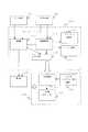
眼光学特性測定装置の光学系100は、例えば、対象物である被測定眼60の光学特性を測定する装置であって、第1照明光学系10と、第1受光光学系20と、第2受光光学系30と、共通光学系40と、調整用光学系50と、第2照明光学系70と、第2送光光学系80とを備える。なお、被測定眼60については、図中、網膜61、角膜62が示されている。
【0012】
第1照明光学系10は、例えば、第1波長の光束を発するための第1光源部11と、集光レンズ12とを備え、第1光源部11からの光束で被測定眼60の網膜(眼底)61上の微小な領域を、その照明条件を適宜設定できるように照明するためのものである。なお、ここでは、一例として、第1光源部11から発せられる照明用の光束の第1波長は、赤外域の波長(例えば、780nm)である。
【0013】
また、第1光源部11は、空間コヒーレンスが大きく、時間コヒーレンスが小さいものが望ましい。ここでは、第1光源部11は、例えば、スーパールミネッセンスダイオード(SLD)であって、輝度の高い点光源を得ることができる。なお、第1光源部11は、SLDに限られるものではなく、例えば、空間コヒーレンス、時間コヒーレンスが大きいレーザー等であっても、回転拡散板等を挿入し、適度に時間コヒーレンスを下げることで、利用することができる。さらに、空間コヒーレンス、時間コヒーレンスが小さいLEDであっても、光量さえ十分であれば、例えば、光路の光源の位置にピンホール等を挿入することで、利用することができる。
【0014】
第1受光光学系20は、例えば、コリメートレンズ21と、被測定眼60の網膜61から反射して戻ってくる光束(第1光束)の一部を、少なくとも、17本のビームに変換する変換部材であるハルトマン板22と、このハルトマン板22で変換された複数のビームを受光するための第1受光部23とを備え、第1光束を第1受光部23に導くためのものである。また、ここでは、第1受光部23は、リードアウトノイズの少ないCCDが採用されているが、CCDとしては、例えば、一般的な低ノイズタイプ、測定用の1000*1000素子の冷却CCD等、適宜のタイプのものを適用することができる。
【0015】
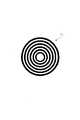
第2照明光学系70は、第2光源72と、プラチドリング71を備える。なお、第2光源72を省略することもできる。図2に、プラチドリングの構成図の一例を示す。プラチドリング(PLACIDO’S DISC)71は、図示のように、複数の同心輪帯からなるパターンの指標を投影するためのものである。なお、複数の同心輪帯からなるパターンの指標は、所定のパターンの指標の一例であり、他の適宜のパターンを用いることができる。そして、後述するアライメント調整が完了した後、複数の同心輪帯からなるパターンの指標を投影することができる。
【0016】
第2送光光学系80は、例えば、後述するアライメント調整及び座標原点、座標軸の測定・調整を主に行うものであって、第2波長の光束を発するための第2光源部31と、集光レンズ32と、ビームスプリッター33を備える。
第2受光光学系30は、集光レンズ34、第2受光部35を備える。第2受光光学系30は、第2照明光学系70から照明されたプラチドリング71のパターンが、被測定眼60の前眼部又は角膜62から反射して戻ってくる光束(第2光束)を、第2受光部35に導く。また、第2光源部31から発せられ被測定眼60の角膜62から反射し、戻ってくる光束を第2受光部35に導くこともできる。なお、第2光源部31から発せられる光束の第2波長は、例えば、第1波長(ここでは、780nm)と異なると共に、長い波長を選択できる(例えば、940nm)。
【0017】
共通光学系40は、第1照明光学系10から発せられる光束の光軸上に配され、第1及び第2照明光学系10及び70、第1及び第2受光光学系20及び30、第2送光光学系80等に共通に含まれ得るものであり、例えば、アフォーカルレンズ42と、ビームスプリッター43、45と、集光レンズ44とを備える。また、ビームスプリッター43は、第2光源部31の波長を被測定眼60に送光(反射)し、被測定眼60の網膜61から反射して戻ってくる第2光束を反射し、一方、第1光源部11の波長を透過するようなミラー(例えば、ダイクロミックミラー)で形成される。ビームスプリッター45は、第1光源部11の波長を被測定眼60に送光(反射)し、被測定眼60の網膜61から反射して戻ってくる第1光束を、透過するようなミラー(例えば、ダイクロミックミラー)で形成される。このビームスプリッター43、45によって、第1及び2光束が、互いに他方の光学系に入りノイズとなることがない。
【0018】
調整用光学系50は、例えば、後述する作動距離調整を主に行うものであって、第3光源部51と、第4光源部55と、集光レンズ52、53と、第3受光部54を備え、主に作動距離調整を行うものである。
つぎに、アライメント調整について説明する。アライメント調整は、主に、第2受光光学系30及び第2送光光学系80により実施される。
【0019】
まず、第2光源部31からの光束は、集光レンズ32、ビームスプリッター33、43、アフォーカルレンズ42を介して、対象物である被測定眼60を略平行な光束で照明する。被測定眼60の角膜62で反射した反射光束は、あたかも角膜62の曲率半径の1/2の点から射出したような発散光束として射出される。この発散光束は、アフォーカルレンズ42、ビームスプリッター43、33及び集光レンズ34を介して、第2受光部35にスポット像として受光される。
【0020】
ここで、この第2受光部35上のスポット像を光軸上から外れている場合、眼光学特性測定装置本体を、上下左右に移動調整し、スポット像が光軸上と一致させる。このように、スポット像が光軸上と一致すると、アライメント調整は完了する。なお、アライメント調整は、被測定眼60の角膜62を第3光源部51により照明し、この照明により得られた被測定眼60の像が第2受光部35上に形成されるので、この像を利用して瞳中心が光軸と一致するようにしてもよい。
【0021】
つぎに、作動距離調整について説明する。作動距離調整は、主に、調整用光学系50により実施される。
まず、作動距離調整は、例えば、第4光源部55から射出された光軸付近の平行な光束を、被測定眼60に向けて照射すると共に、この被測定眼60から反射された光を、集光レンズ52、53を介して第3受光部54で受光することにより行われる。また、被測定眼60が適正な作動距離にある場合、第3受光部54の光軸上に、第4光源部55からのスポット像が形成される。一方、被測定眼60が適正な作動距離から前後に外れた場合、第4光源部55からのスポット像は、第3受光部54の光軸より上又は下に形成される。なお、第3受光部54は、第4光源部55、光軸、第3受光部54を含む面内での光束位置の変化を検出できればいいので、例えば、この面内に配された1次元CCD、ポジションセンシングデバイス(PSD)等を適用できる。
【0022】
つぎに、第1照明光学系10と第1受光光学系20との位置関係を概略的に説明する。
第1受光光学系20には、ビームスプリッター45が挿入されており、このビームスプリッター45によって、第1照明光学系10からの光は、被測定眼60に送光されると共に、被測定眼60からの反射光は、透過される。第1受光光学系20に含まれる第1受光部23は、変換部材であるハルトマン板22を通過した光を受光し、受光信号を生成する。
【0023】
また、第1光源部11と被測定眼60の網膜61とは、共役な関係を形成している。被測定眼60の網膜61と第1受光部23とは、共役である。また、ハルトマン板22と被測定眼60の瞳孔とは、共役な関係を形成している。さらに、第1受光光学系20は、被測定眼60の前眼部である角膜62、及び瞳孔と、ハルトマン板22と略共役な関係を形成している。すなわち、アフォーカルレンズ42の前側焦点は、被測定眼60の前眼部である角膜62及び瞳孔と略一致している。
【0024】
また、第1照明光学系10と第1受光光学系20は、第1光源部11からの光束が、集光する点で反射されたとして、第1受光部23での反射光による信号ピークが最大となるように、連動して移動する。具体的には、第1照明光学系10と第1受光光学系20は、第1受光部23での信号ピークが大きくなる方向に移動し、信号ピークが最大となる位置で停止する。これにより、第1光源部11からの光束は、被測定眼60上で集光する。
【0025】
また、レンズ12は、光源11の拡散光を平行光に変換する。絞り14は、眼の瞳、あるいはハルトマンプレート21と光学的に共役の位置にある。絞り14は、径がハルトマンプレート21の有効範囲より小さく、いわゆるシングルパスの収差計測(受光側だけに目の収差が影響する方法)が成り立つ様になっている。レンズ13は、上記を満たすために、実光線の眼底共役点を前側焦点位置に、さらに、眼の瞳との共役関係を満たすために、後側焦点位置が絞り14と一致するように配置されている。
【0026】
また、光線15は、光線24とビームスプリッター45で共通光路になった後は、近軸的には、光線24と同じ進み方をする。但し、シングルパス測定のときは、それぞれの光線の径は違い、光線15のビーム径は、光線24に比べ、かなり細く設定される。具体的には、光線15のビーム径は、例えば、眼の瞳位置で1mm程度、光線24のビーム径は、7mm程度になることもある(なお、図中、光線15のビームスプリッター45から眼底61までは省略している)。
【0027】
つぎに、変換部材であるハルトマン板22について説明する。
第1受光光学系20に含まれるハルトマン板22は、反射光束を複数のビームに変換する波面変換部材である。ここでは、ハルトマン板22には、光軸と直交する面内に配された複数のマイクロフレネルレンズが適用されている。また、一般に、測定対象部(被測定眼60)について、被測定眼60の球面成分、3次の非点収差、その他の高次収差までも測定するには、被測定眼60を介した少なくとも17本のビームで測定する必要がある。
【0028】
また、マイクロフレネルレンズは、光学素子であって、例えば、波長ごとの高さピッチの輪帯と、集光点と平行な出射に最適化されたブレーズとを備える。ここでのマイクロフレネルレンズは、例えば、半導体微細加工技術を応用した8レベルの光路長差を施したもので、高い集光率(例えば、98%)を達成している。
また、被測定眼60の網膜61からの反射光は、アフォーカルレンズ42、コリメートレンズ21を通過し、ハルトマン板22を介して、第1受光部23上に集光する。したがって、ハルトマン板22は、反射光束を少なくとも、17本以上のビームに変換する波面変換部材を備える。
【0029】
図3は、本発明に関する眼光学特性測定装置の概略電気系200を示すブロック図である。眼光学特性測定装置に関する電気系200は、例えば、演算部210と、制御部220と、表示部230と、メモリ240と、第1駆動部250及び第2駆動部260とを備える。
演算部210は、第1受光部23から得られる受光信号▲4▼、第2受光部35から得られる受光信号▲7▼、第3受光部54から得られる受光信号(10)を入力すると共に、座標原点、座標軸、座標の移動、回転、全波面収差、角膜波面収差、ゼルニケ係数、収差係数、Strehl比、白色光MTF、ランドルト環パターン等を演算する。また、このような演算結果に応じた信号を、電気駆動系の全体の制御を行う制御部220と、表示部230と、メモリ240とにそれぞれ出力する。なお、演算210の詳細は後述する。
【0030】
制御部220は、演算部210からの制御信号に基づいて、第1光源部11の点灯、消灯を制御したり、第1駆動部250及び第2駆動部260を制御するものであり、例えば、演算部210での演算結果に応じた信号に基づいて、第1光源部11に対して信号▲1▼を出力し、プラチドリング71に対して信号▲5▼を出力し、第2光源部31に対して信号▲6▼を出力し、第3光源部51に対して信号▲8▼を出力し、第4光源部55に対して信号▲9▼を出力し、さらに、第1駆動部250及び第2駆動部260に対して信号を出力する。
【0031】
第1駆動部250は、例えば、演算部210に入力された第1受光部23からの受光信号▲4▼に基づいて、第1照明光学系10全体を光軸方向に移動させるものであり、図示しない適宜のレンズ移動手段に対して信号▲2▼を出力すると共に、このレンズ移動手段を駆動する。これにより、第1駆動部250は、第1照明光学系10の移動、調節を行うことができる。
第2駆動部260は、例えば、演算部210に入力された第1受光部23からの受光信号▲4▼に基づいて、第1受光光学系20全体を光軸方向に移動させるものであり、図示しない適宜のレンズ移動手段に対して信号▲3▼を出力すると共に、このレンズ移動手段を駆動する。これにより、第2駆動部260は、第1受光光学系20の移動、調節を行うことができる。
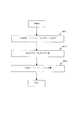
【0032】
図4に、本発明の眼特性測定装置の演算部に関する詳細構成図を示す。演算部210は、測定部111、座標設定部112、アライメント制御部113、マーカー設置部114、入出力部115を備える。
第1受光部23は、被検眼眼底から反射して戻ってくる受光光束から第1受光信号を形成し、測定部111に導く。第2受光部35は、被検眼前眼部の特徴部分及び/又は被検眼前眼部に形成されたマーカーに関する情報を含む受光光束から前眼部の情報を含む第2受光信号を形成し、測定部111及び座標設定部112に導く。
【0033】
測定部111は、第1受光部からの第1受光信号に基づき、被検眼の屈折力又は角膜形状を含む光学特性を求める。測定部111は、特に、第1受光部23からの第1受光信号に基づき、眼光学特性測定を行う。また、測定部111は、特に、第2受光部35からの第2受光信号に基づき、角膜トポグラフィー測定を行う。また、測定部111は、収差結果の演算、また必要に応じてアブレーション量を演算し、その演算結果を入出力部115を介して手術装置に出力する。
【0034】
座標設定部112は、被検眼前眼部の特徴信号を含む第2受光信号に基づき、座標原点及び座標軸の向きを決定する。また、座標設定部112は、第2受光信号中の被検眼前眼部の特徴信号の少なくともいずれか1つに基づき、座標原点、座標軸の回転や移動を求め、測定データと座標軸の関係付けを行う。なお、特徴部分は、瞳位置、瞳中心、角膜中心、虹彩位置、虹彩の模様、瞳の形状、リンバス形状の少なくとも一つを含むものである。例えば、座標設定部112は、瞳中心、角膜中心等の座標原点を設定する。座標設定部112は、第2受光信号に含まれる被検眼前眼部の特徴部分の像に対応する特徴信号に基づき座標系を形成する。また、座標設定部112は、第2受光信号に含まれる被検眼に設けられたマーカーについてのマーカー信号及び被検眼前眼部についての信号に基づき座標系を形成する。座標設定部112は、マーカー信号を含む第2受光信号に基づき、座標原点及び座標軸の向きを決定することができる。座標設定部112は、第2受光信号中のマーカー信号に基づいて、座標原点を求め、第2受光信号中の被検眼前眼部の特徴信号の少なくともいずれか1つに基づき、座標軸の回転や移動を求め、測定データと座標軸の関係付けを行うことができる。または、座標設定部112は、第2受光信号中の前眼部についての特徴信号の少なくともいずれか1つに基づき座標原点を求め、第2受光信号中のマーカー信号に基づいて座標軸の回転や移動を求め、測定データと座標軸の関係付けを行うようにしてもよい。または、座標設定部112は、第2受光信号中の被検眼前眼部の特徴信号の少なくともいずれか1つに基づき、座標原点、座標軸の回転や移動を求め、測定データと座標軸の関係付けを行うようにしてもよい。
【0035】
第1照明光学系10と、第1受光光学系20と、第2受光光学系30と、共通光学系40と、調整用光学系50と、第2照明光学系70と、第2送光光学系80等のいずれかひとつ又は複数又は全ては、適宜光学系100のアライメント部に掲載される。アライメント制御部113は、第2受光部により得られた第2受光信号に基づく座標設定部112の演算結果に従い、被検眼の動きに応じてこのアラインメント部を移動可能とする。マーカー設置部114は、座標設定部112により設定された座標系に基づき被検眼前眼部にこの座標系に関連づけられたマーカーを形成する。入出力部115は、測定部又は座標設定部からの、収差量、座標原点、座標軸、座標軸の回転、移動、アブレーション量等のデータや演算結果を手術装置に出力するためのインタフェースである。表示部240は、測定部111により求めれられた被検眼の光学特性を、上記座標設定部により形成された座標系との関係で表示を行う。
【0036】
手術装置300は、手術制御部121、加工部122、メモリ部123を含む。手術制御部121、は、加工部122を制御し、角膜切削等の手術の制御を行う。加工部122は、角膜切削等の手術のためのレーザを含む。手術メモリ部123は、切削に関するデータ、ノモグラム、手術計画等の手術のためのデータが記憶されている。
【0037】
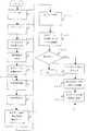
つぎに、本発明の関する眼特性測定装置による座標の決定についてのフローチャートを説明する。
(1)特徴部分に基づき座標を決定する第1方式(単測定)
図5は、本発明に関する眼光学特性測定装置の動作を示す第1の実施の形態のフローチャートである。
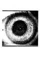
まず、第2受光部35からの信号は、表示部230のモニタ画面上に前眼部像として形成される。図6に、前眼部像の説明図を示す。図中「×」は瞳中心、「○」は角膜頂点(中心)、星マークはアライメントマーカーをそれぞれ示す。実際のアライメントマーカーは円形など別の形でも良い。瞳中心は、主に、手術装置の原点として扱われる。角膜中心は、主に、CCD又は機械の中心として扱われる。図示のように、プラチドリング1の像に加え、第2光源部31からの光が被検眼角膜頂点付近で輝点として現れる。その被検眼前眼部像を観察しながら、眼光学特性測定装置を被検眼に対してXY方向のアライメントを行うこのときZ方向のアライメントも調整用光学系50より行う(S101)。
【0038】
つぎに、例えば、輪帯内に現れる第1受光信号と第2受光信号を読み込む(S103)。特徴部分を含む被検眼前眼部の像を示す第2受光信号に含まれる特徴信号を利用して、座標原点及び軸方向を決定し、基準座標系を設定する(S105)。ここで、被検眼前眼部の特徴部分として、例えば、瞳位置、虹彩位置、虹彩の模様、瞳の形状、リンバス形状、被検眼前眼部に形成されたマーカー(マーカーがある場合)等が挙げられる。基準座標系は、手術装置300で用いられる座標原点とすることがより望ましく、例えば、被検眼瞳位置、被検眼の虹彩位置、瞳の形状、リンバス形状、被検眼の虹彩の模様(虹彩紋理)等から、求められる。座標原点としては、瞳中心や角膜中心などが考えられる。座標軸は、マーカーが形成されている場合、例えば、マーカーと瞳中心を通る直線とすることで設定することができる。座標回転・移動は、マーカーが形成されている場合、例えば、マーカーの回転・移動により測定することができる。
【0039】
また、マーカー以外にも、瞳虹彩の模様(虹彩紋理)により座標軸及び回転(サイクロトーション)を測定することができる。ここで、図7に、座標軸・回転の測定に関する説明図を示す。まず、図7(a)に示すように、例えば、瞳中心を中心にした輪帯上で反射強度等によりパターンを解析する。すると、図7(b)に示すように、角度に対する反射強度のパターンが作成される。このパターンにより、座標軸を設定することができる。また、この解析されたパターンを周上でマッチングさせ、座標回転を測定することができる。すなわち、眼が回転(サイクロトーション)すると、このような強度のグラフは回転角度だけ横ずれする。その横ずれの量は、各測定値と基準グラフの相関の最も大きい角度で求めることができる。
【0040】
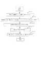
図8に、基準座標系の設定のフローチャートを示す。これは、ステップS105の詳細フローチャートであり、瞳中心計算、測定輪帯測定を行う。
まず、座標原点を決定するため、瞳中心の計算する(瞳のエッジ全周から簡単に求まる。)(S501)。つぎに、測定輪帯を決定する(例えば、瞳孔径より+0.5 mm)。エッジにかかったら、所定長、例えば+0.1 mmづつ増やす(S503)。つぎに、座標軸を決定するため、被検眼の特徴部分に基づき、角度を決定する(S505)。つぎに、円周方向の強度分布を記録する(S507)。つぎに、強度分布のデータをハードディスク(HD)等に保存するとともに、瞳孔径も保存する(S509)。
【0041】
つぎに、図5のフロチャートに戻ると、第1受光部23により、変換部材であるハルトマン板22を通過した光束の受光位置データが、当初CCDの座標系(測定座標系)で得られるが、これを、基準座標系での座標値に変換する(S107)。また、第1又は第2受光信号に基づき光学特性が求められる(S109)。ここで、光学特性とは、例えば、収差(角膜、眼内、眼)屈折力、角膜形状などである。すなわち、第1受光信号に基づき、被検眼屈折力が、また、第2受光信号に基づき、角膜形状が求められる。つぎに、測定された光学特性を表示する(S111)。そして、出力データを演算する(S113)。出力データとしては、例えば、基準座標系のデータ、測定データ、被検眼の収差量それ自体、光学特性データ、手術装置で切除するために必要とされるアブレーション量などを演算して求める。つぎに、これらの出力データを表示する(S115)。さらに、必要に応じて、これらの出力データを出力する(S117)。ここで、出力の形態は、例えば、次の態様がある。
【0042】
オフライ的な態様で、フロッピー(登録商標)ディスク、CD-ROM等の記録媒体や、信号ライン無線ライン等のインタフェースで出力され、その後に手術が別の時期に行われる形態。
出力データがオンラインで手術装置300に信号ライン等のインタフェースで繋がっており、手術の際に連続的又は切換により被検眼の光学特性を測定するような形態。
以上のように、データ出力の後、測定が未了であれば繰り返し、終了であれば測定終了となる(S121)。
【0043】
(2)特徴部分に基づき座標を決定する第1方式(複数回測定)
図9に、本発明に関する眼光学特性測定装置の動作を示す第2の実施の形態のフローチャートを示す。
ここでは、第1実施の形態と共通の部分(S101〜S115)は、省略する。上述のように、出力データが表示された後(S115)、これら出力データと手術計画に基づきレーザ手術装置300を制御する(S201)。データ出力の後、測定終了であれば測定終了となり、測定が未了であれば次のルーチンに進む(S203)。測定終了でない場合、さらに、第1及び第2受光信号を取り込む(S205)。これらの信号に基づき、測定座標系と基準座標系との差を演算して確認する(S207)。演算結果に応じて、受光データを基準座標系に変換する(S209)。その後ステップS111に移る。
【0044】
ここで、図10に、測定座標系と基準座標系との差を確認するためのフローチャートを示す。これは、ステップS207の詳細フローチャートであり、瞳中心計算、測定輪帯測定などを相関処理して、合致した座標位置を求めるものである。
まず、保存してあった基準グラフデータO(θ)と瞳径をハードディスク(HD)等のメモリ240から読み込む(S701)。この基準グラフデータO(θ)は、例えば、図7で示した輪帯上の強度分布を用いることができる。つぎに、読み取ったデジタルに基づき瞳中心を求める(S703)。つぎに、瞳径を測り、基準グラフデータO(θ)を得たときの瞳径と違ったら明るさを調整する(S705)。つぎに、基準グラフデータと同様に、測定されたグラフデータF(θ)、例えば輪帯上の強度分布を測定する(S707)。つぎに、今回の測定されたグラフデータF(θ)と基準グラフデータO(θ)の相関が最も高くなるような、角度A回転した測定されたグラフデータF(θ−A)を求める(S709)。こうして、測定時より眼が角度A廻旋していることがわかる(S711)。
【0045】
(3)被検眼に形成されたマーカーを利用して座標系を設定する第2方式
図11に、本発明に関する眼光学特性測定装置の動作を示す第3の実施の形態のフローチャートである。
まず、マーカーを被検眼に設置する(S301)。ここで、第2光源部31からの光が被検眼角膜頂点付近で輝点として現れる。その被検眼前眼部像とマーカーを観察しながら、眼光学特性測定装置を被検眼に対してXY方向のアライメントを行う(S303)。つぎに、輪帯内に現れる第1受光信号と第2受光信号を読み込む(S305)。被検眼前眼部の特徴部分の像を示す第2受光信号に含まれる特徴信号、被検眼に設けられたマーカーを利用して、座標原点及び軸方向を決定し、基準座標系を設定する(S307)。なお、マーカーを複数設置することにより、マーカーのみから座標原点及び軸方向を決定するようにしても良い。
また、第1受光信号とマーカーから又は、瞳中心・角膜中心とマーカー等からこれらを決定してもよい。
【0046】
以下ステップS107〜S115、S201〜S205は、上述と同様である。その後、測定座標系と基準座標系との差の演算・確認処理(S309)及び受光データを基準座標系に変換する処理(S311)については、上述の通りにある。ただし、基準グラフデータ、測定グラフデータとして上述のような強度分布の他にも、複数マーカーを利用したり、マーカーと瞳中心、角膜中心又は第1受光信号等を利用することができる。
【0047】
つぎに、図12に、アブレーション量を求めるフローチャートを示す。通常、この処理は、演算部210の演算結果に基づき、手術装置300内の手術制御部121で実行されるものである。その他、眼特性測定装置100側の演算部210等でこの処理を実行することもでき、その場合、眼特性測定装置100では、手術装置300に関するデータを入力又は記憶する手段をさらに備え、演算されて得られたアブレーション量等は入出力部115を介して手術装置300に伝送することができる。処理フローとしては、まず、収差係数、アライメント位置データを受信する(S601)。つぎに、収差係数から収差量を計算する(S603)。つぎに、収差量からアブレーション量を計算する(S605)。
【0048】
【発明の効果】
本発明によると、以上説明した通り、眼特性の測定装置、手術装置、眼の各々の座標原点及び座標軸の関係付けを十分に達成することができる眼特性測定装置を提供することができる。
また、本発明によると、眼の回転・移動に対しても、座標軸との関係付けを行うことができる。さらに、本発明によると、眼の動きに応じて対処可能とすることができる。
【図面の簡単な説明】
【図1】本発明に関する眼光学特性測定装置の概略光学系を示す図。
【図2】本発明に関する眼光学特性測定装置の電気的構成を示す電気系ブロック図。
【図3】本発明に関する眼光学特性測定装置のフローチャート。
【図4】本発明の眼特性測定装置の演算部に関する詳細構成図。
【図5】本発明に関する眼光学特性測定装置の動作を示す第1の実施の形態のフローチャート。
【図6】前眼部像の説明図。
【図7】座標軸・回転の測定に関する説明図。
【図8】基準座標系の設定のフローチャート。
【図9】本発明に関する眼光学特性測定装置の動作を示す第2の実施の形態のフローチャート。
【図10】測定座標系と基準座標系との差を確認するためのフローチャート。
【図11】本発明に関する眼光学特性測定装置の動作を示す第3の実施の形態のフローチャート。
【図12】アブレーション量を求めるフローチャート。
【符号の説明】
10 第1照明光学系
11、31、51、55 第1〜4光源部
12、32、34、44、52、53 集光レンズ
20 第1受光光学系
21 コリメートレンズ
22 ハルトマン板
23、35、54 第1〜3受光部
30 第2受光光学系
33、43、45 ビームスプリッター
40 共通光学系
42 アフォーカルレンズ
50 調整用光学系
60 被測定眼
70 第2照明光学系
71 プラチドリング
80 第2送光光学系
100 眼特性測定装置の光学系
111 測定部
112 座標設定部
113 アライメント制御部
114 マーカー設置部
115 入出力部
121 手術制御部
122 加工部
123 メモリ部
200 眼特性測定装置の電気系
230 表示部
300 手術装置[0001]
BACKGROUND OF THE INVENTION
The present invention relates to an eye characteristic measuring apparatus, and more particularly to an eye characteristic measuring apparatus that measures optical characteristics of an eye, associates it with a predetermined coordinate system of an eye to be examined, displays it, and the like.
[0002]
[Prior art]
In recent years, optical instruments used for medical purposes have spread very widely. In particular, in the ophthalmology, this optical apparatus is widely used as an optical characteristic measuring device that performs eye functions such as eye refraction and adjustment, and examination of the inside of the eyeball. In addition, the measurement results of these various tests are important, for example, under what measurement conditions the patient's eye to be tested is placed. For example, since the pupil of the eye is small in a bright place and large in a dark place, it is necessary to consider illuminance as a measurement condition, and the measurement range of the eye to be measured is also important.
[0003]
In addition, the shape of the retina, cornea, and other parts contained in the eye is often unique to each patient, so that an ophthalmologist or the like can quickly diagnose a patient's eye to be measured, etc. It is desirable to display various data related to each part of the eye to be measured collectively or by selecting desired data. Thereby, an ophthalmologist or the like can easily explain various diagnoses (findings) to the patient.
[0004]
Moreover, in general, corneal topography includes many predictions such as corneal incision and corneal cutting, clinical trials after corneal transplantation, design and evaluation of contact lenses for myopia and hyperopia, corneal diagnosis and disease determination, etc. It is effective for use. Conventional corneal shape measurement methods include, for example, a plastic seed disk technique, a three-dimensional photography technique, a moire technique, and a topography interference technique.
[0005]
[Problems to be solved by the invention]
However, the conventional eye characteristic measuring apparatus has been processed such that the coordinates of the measuring apparatus itself, for example, the center of the light receiving unit is set as the coordinate origin. Therefore, according to such a coordinate system, there is a case where the relationship between the measurement data and the eye is not sufficiently taken and is not necessarily appropriate.
[0006]
In view of the above points, an object of the present invention is to provide an eye characteristic measuring apparatus, a surgical apparatus, and an eye characteristic measuring apparatus that can sufficiently achieve the relationship between the coordinate origin and coordinate axis of each eye. .
It is another object of the present invention to relate the coordinate axis to the rotation / movement of the eye. Furthermore, an object of the present invention is to be able to cope with the movement of the eye.
[0007]
[Means for Solving the Problems]
According to the first solution of the present invention,
A first illumination optical system for illuminating the fundus of the eye to be examined with the first light beam from the first light source unit, the first light source unit emitting a first light beam of a first wavelength;
A first light receiving optical system that includes a first light receiving unit that forms a first light receiving signal from the received light beam, and that guides the light beam reflected and returned from the fundus of the subject's eye to the first light receiving unit;
A second light receiving unit that forms a second light receiving signal including information on the anterior segment from the received light flux;Includes at least one of pupil position, pupil center, corneal center, iris position, iris pattern, pupil shape, and limbus shape A second light receiving optical system for guiding a second light beam including information on the characteristic portion to the second light receiving unit;
Based on the first light receiving signal from the first light receiving unit, a measuring unit for obtaining optical characteristics including the refractive power of the eye to be examined,
Of the anterior segment of the eye to be examined included in the second received light signalSaid Corresponding to the image of the characteristic part,Includes at least one of pupil position, pupil center, corneal center, iris position, iris pattern, pupil shape, and limbus shape Based on feature signalBy setting the pupil center or corneal center as the coordinate origin and determining the orientation of the coordinate axis A coordinate setting unit that forms a coordinate system;
Obtained by the measurement unitMera A display unit that displays the optical characteristics of the eye to be examined in relation to the coordinate system formed by the coordinate setting unit;
Apparatus for measuring eye characteristicsThe provide.
[0008]
According to the second solution of the present invention,
A second illumination optical system for illuminating a pattern for detecting a characteristic portion of the anterior segment of the eye to be examined;
A second light receiving optical system that has a second light receiving unit that forms a second light receiving signal from the received light beam, and that guides the light beam reflected back from the eye to be examined to the second light receiving unit;
A measurement unit for obtaining optical characteristics including a cornea shape of the eye to be examined based on a second light reception signal from the second light reception unit;
Of the anterior ocular segment to be examined included in the second received light signal,Includes at least one of pupil position, pupil center, corneal center, iris position, iris pattern, pupil shape, and limbus shape Corresponds to the feature image, Pupil position, pupil center, cornea center, iris position, iris pattern, pupil shape, and limbus shape Based on feature signalBy setting the pupil center or corneal center as the coordinate origin and determining the orientation of the coordinate axis A coordinate setting unit that forms a coordinate system;
Obtained by the measurement unitMera A display unit that displays the optical characteristics of the eye to be examined in relation to the coordinate system formed by the coordinate setting unit;
An eye characteristic measuring apparatus comprising:
[0009]
According to the third solution of the present invention,
A first illumination optical system for illuminating the fundus of the eye to be examined with the first light beam from the first light source unit, the first light source unit emitting a first light beam of a first wavelength;
A first light receiving optical system that includes a first light receiving unit that forms a first light receiving signal from the received light beam, and that guides the light beam reflected and returned from the fundus of the subject's eye to the first light receiving unit;
A second light-receiving unit that forms a second light-receiving signal including information on the anterior ocular segment from the received light beam, and guides the second light beam including information related to the marker formed on the anterior eye portion of the eye to the second light-receiving unit. Two light receiving optical systems;
Based on the first light receiving signal from the first light receiving unit, a measuring unit for obtaining optical characteristics including the refractive power of the eye to be examined,
A marker signal for a marker provided on the eye to be examined and included in the second light receiving signal,Includes at least one of pupil position, pupil center, corneal center, iris position, iris pattern, pupil shape, and limbus shape Corresponds to the feature image, Pupil position, pupil center, cornea center, iris position, iris pattern, pupil shape, and limbus shape Based on feature signalBy setting the pupil center or corneal center as the coordinate origin and determining the orientation of the coordinate axis A coordinate setting unit that forms a coordinate system;
Obtained by the measurement unitMera A display unit that displays the optical characteristics of the eye to be examined in relation to the coordinate system formed by the coordinate setting unit;
An eye characteristic measuring apparatus comprising:
[0010]
According to the fourth solution of the present invention,
It has a pattern for detecting the characteristic part of the anterior segment of the eye to be examined,car A second illumination optical system for illuminating the subject's eye provided with
A second light receiving optical system that has a second light receiving unit that forms a second light receiving signal from the received light beam, and that guides the light beam reflected back from the eye to be examined to the second light receiving unit;
A measurement unit for obtaining optical characteristics including a cornea shape of the eye to be examined based on a second light reception signal from the second light reception unit;
Marker signals of markers provided in the eye to be examined and included in the second received light signal and the anterior eye portion of the eye to be examined.Includes at least one of pupil position, pupil center, corneal center, iris position, iris pattern, pupil shape, and limbus shape Corresponds to the feature image, Pupil position, pupil center, cornea center, iris position, iris pattern, pupil shape, and limbus shape Based on feature signalBy setting the pupil center or corneal center as the coordinate origin and determining the orientation of the coordinate axis A coordinate setting unit that forms a coordinate system;
Obtained by the measurement unitMera A display unit that displays the optical characteristics of the eye to be examined in relation to the coordinate system formed by the coordinate setting unit;
An eye characteristic measuring apparatus comprising:
[0011]
DETAILED DESCRIPTION OF THE INVENTION
Hereinafter, embodiments of the present invention will be described in detail with reference to the drawings.
1. Explanation of the principle of ocular optical characteristics measurement
FIG. 1 is a diagram showing a schematic
The
[0012]
The first illumination
[0013]
The first light source unit 11 preferably has a large spatial coherence and a small temporal coherence. Here, the first light source unit 11 is a super luminescence diode (SLD), for example, and can obtain a point light source with high luminance. The first light source unit 11 is not limited to the SLD. For example, even with a laser having a large spatial coherence or temporal coherence, by inserting a rotating diffusion plate or the like and appropriately reducing the temporal coherence, Can be used. Furthermore, even an LED with small spatial coherence and temporal coherence can be used by inserting a pinhole or the like at the position of the light source in the optical path as long as the amount of light is sufficient.
[0014]
The first light receiving
[0015]
The second illumination
[0016]
The second light transmission optical system 80 mainly performs alignment adjustment, coordinate origin, and coordinate axis measurement / adjustment, which will be described later, for example, and includes a second
The second light receiving
[0017]
The common
[0018]
The adjustment
Next, alignment adjustment will be described. The alignment adjustment is mainly performed by the second light receiving
[0019]
First, the light beam from the second
[0020]
Here, when the spot image on the second
[0021]
Next, the working distance adjustment will be described. The working distance adjustment is mainly performed by the adjustment
First, the working distance adjustment is performed, for example, by irradiating a parallel light beam near the optical axis emitted from the fourth light source unit 55 toward the
[0022]
Next, the positional relationship between the first illumination
A beam splitter 45 is inserted into the first light receiving
[0023]
Further, the first light source unit 11 and the retina 61 of the
[0024]
Further, the first illumination
[0025]
The
[0026]
The
[0027]
Next, the
The
[0028]
The micro Fresnel lens is an optical element, and includes, for example, an annular zone having a height pitch for each wavelength and a blaze optimized for emission parallel to the focal point. The micro Fresnel lens here is, for example, an optical path length difference of 8 levels applying a semiconductor microfabrication technique, and achieves a high light collection rate (for example, 98%).
The reflected light from the retina 61 of the
[0029]
FIG. 3 is a block diagram showing a schematic
The
[0030]
The
[0031]
For example, the
For example, the
[0032]
In FIG. 4, the detailed block diagram regarding the calculating part of the eye characteristic measuring apparatus of this invention is shown. The
The first
[0033]
The measuring unit 111 obtains optical characteristics including the refractive power of the eye to be examined or the corneal shape based on the first received light signal from the first light receiving unit. In particular, the measurement unit 111 performs eye optical characteristic measurement based on the first light reception signal from the first
[0034]
The coordinate setting unit 112 determines the coordinate origin and the direction of the coordinate axis based on the second received light signal including the characteristic signal of the anterior eye part to be examined. In addition, the coordinate setting unit 112 obtains the coordinate origin and the rotation and movement of the coordinate axis based on at least one of the characteristic signals of the anterior segment of the eye to be examined in the second received light signal, and associates the measurement data with the coordinate axis. Do. The characteristic portion includes at least one of a pupil position, a pupil center, a cornea center, an iris position, an iris pattern, a pupil shape, and a limbus shape. For example, the coordinate setting unit 112 sets coordinate origins such as the pupil center and the cornea center. The coordinate setting unit 112 forms a coordinate system based on the feature signal corresponding to the image of the feature portion of the anterior eye portion to be examined included in the second light reception signal. The coordinate setting unit 112 forms a coordinate system based on the marker signal for the marker provided on the eye to be examined and the signal for the anterior eye part to be examined, which are included in the second light receiving signal. The coordinate setting unit 112 can determine the coordinate origin and the direction of the coordinate axis based on the second light receiving signal including the marker signal. The coordinate setting unit 112 obtains the coordinate origin based on the marker signal in the second light reception signal, and rotates the coordinate axis based on at least one of the characteristic signals of the anterior eye segment in the second light reception signal. The movement can be obtained, and the measurement data can be related to the coordinate axis. Alternatively, the coordinate setting unit 112 obtains the coordinate origin based on at least one of the feature signals for the anterior segment in the second light reception signal, and rotates or moves the coordinate axis based on the marker signal in the second light reception signal. And the correlation between the measurement data and the coordinate axes may be performed. Alternatively, the coordinate setting unit 112 obtains the coordinate origin and the rotation and movement of the coordinate axis based on at least one of the characteristic signals of the anterior segment of the eye to be examined in the second light reception signal, and associates the measurement data with the coordinate axis. You may make it perform.
[0035]
First illumination
[0036]
The
[0037]
Next, a flowchart for determining coordinates by the eye characteristic measuring apparatus according to the present invention will be described.
(1) The first method (single measurement) that determines coordinates based on the characteristic part
FIG. 5 is a flowchart of the first embodiment showing the operation of the eye optical characteristic measuring apparatus according to the present invention.
First, a signal from the second
[0038]
Next, for example, a first received light signal and a second received light signal appearing in the annular zone are read (S103). Using the feature signal included in the second received light signal indicating the image of the anterior ocular segment including the feature portion, the coordinate origin and the axial direction are determined, and the reference coordinate system is set (S105). Here, as the characteristic part of the anterior eye part to be examined, for example, a pupil position, an iris position, an iris pattern, a pupil shape, a limbus shape, a marker (if there is a marker) formed on the anterior eye part to be examined, etc. Can be mentioned. The reference coordinate system is more preferably the coordinate origin used in the
[0039]
In addition to the marker, the coordinate axis and rotation (cyclotorsion) can be measured by the iris pattern (iris pattern). Here, FIG. 7 shows an explanatory diagram relating to the measurement of coordinate axes and rotation. First, as shown in FIG. 7A, for example, a pattern is analyzed by reflection intensity or the like on an annular zone centered on the pupil center. Then, as shown in FIG.7 (b), the pattern of the reflection intensity with respect to an angle is created. With this pattern, coordinate axes can be set. Further, the analyzed pattern can be matched on the circumference to measure the coordinate rotation. That is, when the eye rotates (cyclotorsion), such a graph of intensity shifts laterally by the rotation angle. The amount of the lateral shift can be obtained at the angle at which the correlation between each measured value and the reference graph is the largest.
[0040]
FIG. 8 shows a flowchart for setting the reference coordinate system. This is a detailed flowchart of step S105, and pupil center calculation and measurement ring zone measurement are performed.
First, in order to determine the coordinate origin, the center of the pupil is calculated (which is easily obtained from the entire circumference of the pupil edge) (S501). Next, the measurement ring zone is determined (for example, +0.5 mm from the pupil diameter). When it reaches the edge, it is increased by a predetermined length, for example, +0.1 mm (S503). Next, in order to determine a coordinate axis, an angle is determined based on the characteristic part of the eye to be examined (S505). Next, the intensity distribution in the circumferential direction is recorded (S507). Next, the intensity distribution data is stored in a hard disk (HD) or the like, and the pupil diameter is also stored (S509).
[0041]
Next, returning to the flowchart of FIG. 5, the first
[0042]
In an off-line manner, the data is output via a recording medium such as a floppy (registered trademark) disk or CD-ROM, or an interface such as a signal line wireless line, after which surgery is performed at another time.
The output data is connected online to the
As described above, after the data output, if the measurement is not completed, the measurement is repeated, and if the measurement is completed, the measurement is completed (S121).
[0043]
(2) The first method for determining coordinates based on the characteristic part (multiple measurements)
FIG. 9 shows a flowchart of the second embodiment showing the operation of the eye optical characteristic measuring apparatus according to the present invention.
Here, portions common to the first embodiment (S101 to S115) are omitted. As described above, after the output data is displayed (S115), the laser
[0044]
Here, FIG. 10 shows a flowchart for confirming the difference between the measurement coordinate system and the reference coordinate system. This is a detailed flowchart of step S207, in which pupil center calculation, measurement ring zone measurement, and the like are subjected to correlation processing to obtain a matching coordinate position.
First, the stored reference graph data O (θ) and pupil diameter are read from a
[0045]
(3) A second method for setting a coordinate system using a marker formed on the eye to be examined
FIG. 11 is a flowchart of the third embodiment showing the operation of the ophthalmic optical characteristic measuring apparatus according to the present invention.
First, a marker is placed on the eye to be examined (S301). Here, the light from the second
Alternatively, these may be determined from the first light reception signal and the marker or from the pupil center / corneal center and the marker.
[0046]
Steps S107 to S115 and S201 to S205 are the same as described above. Thereafter, the calculation / confirmation processing (S309) of the difference between the measurement coordinate system and the reference coordinate system and the processing (S311) for converting the received light data into the reference coordinate system are as described above. However, in addition to the above-described intensity distribution as the reference graph data and the measurement graph data, a plurality of markers, a marker and the pupil center, the cornea center, the first light reception signal, or the like can be used.
[0047]
Next, FIG. 12 shows a flowchart for obtaining the ablation amount. Usually, this process is executed by the
[0048]
【The invention's effect】
According to the present invention, as described above, it is possible to provide an eye characteristic measuring apparatus, a surgical apparatus, and an eye characteristic measuring apparatus that can sufficiently achieve the relationship between the coordinate origin and coordinate axis of each eye.
Further, according to the present invention, it is possible to relate the coordinate axis to the rotation / movement of the eye. Furthermore, according to the present invention, it is possible to cope with the movement of the eye.
[Brief description of the drawings]
FIG. 1 is a diagram showing a schematic optical system of an eye optical characteristic measuring apparatus according to the present invention.
FIG. 2 is an electrical system block diagram showing an electrical configuration of an eye optical characteristic measuring apparatus according to the present invention.
FIG. 3 is a flowchart of an eye optical characteristic measuring apparatus according to the present invention.
FIG. 4 is a detailed configuration diagram relating to a calculation unit of the eye characteristic measuring apparatus according to the present invention.
FIG. 5 is a flowchart of the first embodiment showing the operation of the eye optical characteristic measuring apparatus according to the present invention.
FIG. 6 is an explanatory diagram of an anterior segment image.
FIG. 7 is an explanatory diagram regarding measurement of coordinate axes and rotation.
FIG. 8 is a flowchart for setting a reference coordinate system.
FIG. 9 is a flowchart of the second embodiment showing the operation of the eye optical characteristic measuring apparatus according to the present invention.
FIG. 10 is a flowchart for confirming a difference between a measurement coordinate system and a reference coordinate system.
FIG. 11 is a flowchart of the third embodiment showing the operation of the eye optical characteristic measuring apparatus according to the present invention.
FIG. 12 is a flowchart for obtaining an ablation amount.
[Explanation of symbols]
10 First illumination optical system
11, 31, 51, 55 1st-4th light source part
12, 32, 34, 44, 52, 53 Condensing lens
20 First light receiving optical system
21 Collimating lens
22 Hartmann board
23, 35, 54 1st-3rd light-receiving part
30 Second light receiving optical system
33, 43, 45 Beam splitter
40 Common optics
42 Afocal lens
50 Adjustment optical system
60 Eye to be measured
70 Second illumination optical system
71 Pratide ring
80 Second light transmission optical system
100 Optical system of eye characteristic measuring device
111 Measuring unit
112 Coordinate setting part
113 Alignment controller
114 Marker installation part
115 Input / output section
121 Surgery control unit
122 Processing part
123 Memory part
200 Electrical system of the eye characteristic measuring device
230 Display section
300 Surgical device
Claims (13)
Translated fromJapanese受光光束から第1受光信号を形成する第1受光部を有し、被検眼眼底から反射して戻ってくる光束を該第1受光部に導く第1受光光学系と、
受光光束から前眼部の情報を含む第2受光信号を形成する第2受光部を有し、被検眼前眼部の、瞳位置、瞳中心、角膜中心、虹彩位置、虹彩の模様、瞳の形状、リンバス形状の少なくとも一つを含むものである特徴部分に関する情報を含む第2光束を該第2受光部に導く第2受光光学系と、
第1受光部からの第1受光信号に基づき、被検眼の屈折力を含む光学特性を求める測定部と、
第2受光信号に含まれる被検眼前眼部の前記特徴部分の像に対応する、瞳位置、瞳中心、角膜中心、虹彩位置、虹彩の模様、瞳の形状、リンバス形状の少なくとも一つを含むものである特徴信号に基づき、瞳中心又は角膜中心を座標原点として設定し、座標軸の向きを決定することにより座標系を形成する座標設定部と、
上記測定部により求められた被検眼の光学特性を、上記座標設定部により形成された座標系との関係で表示を行う表示部と
を備えた眼特性測定装置。A first illumination optical system for illuminating the fundus of the eye to be examined with the first light beam from the first light source unit, the first light source unit emitting a first light beam of a first wavelength;
A first light receiving optical system that includes a first light receiving unit that forms a first light receiving signal from the received light beam, and that guides the light beam reflected and returned from the fundus of the subject's eye to the first light receiving unit;
A second light-receiving unit that forms a second light-receiving signal that includes information on the anterior segment from the received light beam, and thepupil position, pupil center, corneal center, iris position, iris pattern, and pupil A second light receiving optical system for guiding a second light beam including information ona characteristic portionincluding at least one of a shape and a shape of a limbus to the second light receiving unit;
Based on the first light receiving signal from the first light receiving unit, a measuring unit for obtaining optical characteristics including the refractive power of the eye to be examined,
Corresponding to the image ofthe characteristic part of the eye anterior part included in the second light receiving signal,the pupil position, the pupil center, the corneal center, the iris position, the pattern of the iris, pupil shape, including at least one limbus shape a coordinate setting unit for forming a coordinate systemby based on the feature signalisDressings,it sets the pupil center or corneal center as a coordinate origin, to determine the coordinate axis direction,
The optical characteristics of the eye was determinedMera by the measuring unit, the eye characteristic measuring device having a display section for performing display in relation to the coordinate system formed by the coordinate setting unit.
受光光束から第2受光信号を形成する第2受光部を有し、被検眼から反射して戻ってくる光束を該第2受光部に導く第2受光光学系と、
第2受光部からの第2受光信号に基づき、被検眼の角膜形状を含む光学特性を求める測定部と、
第2受光信号に含まれる被検眼前眼部の、瞳位置、瞳中心、角膜中心、虹彩位置、虹彩の模様、瞳の形状、リンバス形状の少なくとも一つを含むものである特徴部分の像に対応する、瞳位置、瞳中心、角膜中心、虹彩位置、虹彩の模様、瞳の形状、リンバス形状の少なくとも一つを含むものである特徴信号に基づき、瞳中心又は角膜中心を座標原点として設定し、座標軸の向きを決定することにより座標系を形成する座標設定部と、
上記測定部により求められた被検眼の光学特性を、上記座標設定部により形成された座標系との関係で表示を行う表示部と
を備えた眼特性測定装置。A second illumination optical system for illuminating a pattern for detecting a characteristic portion of the anterior segment of the eye to be examined;
A second light receiving optical system that has a second light receiving unit that forms a second light receiving signal from the received light beam, and that guides the light beam reflected back from the eye to be examined to the second light receiving unit;
A measurement unit for obtaining optical characteristics including a cornea shape of the eye to be examined based on a second light reception signal from the second light reception unit;
Corresponding to an imageof a characteristic portionincluding at least one of thepupil position, the pupil center, the cornea center, the iris position, the iris pattern, the pupil shape, and the limbus shape of the anterior segment of the eye to be examined included in the second received light signal. Basedon a feature signalthat includes at least one of pupil position, pupil center, corneal center, iris position, iris pattern, pupil shape, and limbus shape, the pupil center or corneal center is set as the coordinate origin, and the direction of the coordinate axis A coordinate setting unit that forms a coordinate systemby determining
The optical characteristics of the eye was determinedMera by the measuring unit, the eye characteristic measuring device having a display section for performing display in relation to the coordinate system formed by the coordinate setting unit.
上記アライメント部は、上記第2受光部により得られた第2受光信号に基づき、被検眼の動きに応じて移動可能に構成したことを特徴とする請求項1乃至5のいずれかに記載の眼特性測定装置。An alignment unit equipped with the first light receiving optical system or the second light receiving optical system;
The alignment section, the basis of the second light receiving signal obtained by the second light receiving portion, the eye according to any one of claims 1 to5, characterized by being configured to be movable in response to movement of the eye Characteristic measuring device.
受光光束から第1受光信号を形成する第1受光部を有し、被検眼眼底から反射して戻ってくる光束を該第1受光部に導く第1受光光学系と、
受光光束から前眼部の情報を含む第2受光信号を形成する第2受光部を有し、被検眼前眼部に形成されたマーカーに関する情報を含む第2光束を第2受光部に導く第2受光光学系と、
第1受光部からの第1受光信号に基づき、被検眼の屈折力を含む光学特性を求める測定部と、
第2受光信号に含まれる被検眼に設けられたマーカーについてのマーカー信号及び被検眼前眼部の、瞳位置、瞳中心、角膜中心、虹彩位置、虹彩の模様、瞳の形状、リンバス形状の少なくとも一つを含むものである特徴部分の像に対応する、瞳位置、瞳中心、角膜中心、虹彩位置、虹彩の模様、瞳の形状、リンバス形状の少なくとも一つを含むものである特徴信号に基づき、瞳中心又は角膜中心を座標原点として設定し、座標軸の向きを決定することにより座標系を形成する座標設定部と、
上記測定部により求められた被検眼の光学特性を、上記座標設定部により形成された座標系との関係で表示を行う表示部と
を備えた眼特性測定装置。A first illumination optical system for illuminating the fundus of the eye to be examined with the first light beam from the first light source unit, the first light source unit emitting a first light beam of a first wavelength;
A first light receiving optical system that includes a first light receiving unit that forms a first light receiving signal from the received light beam, and that guides the light beam reflected and returned from the fundus of the subject's eye to the first light receiving unit;
A second light-receiving unit that forms a second light-receiving signal including information on the anterior ocular segment from the received light beam, and guides the second light beam including information related to the marker formed on the anterior eye portion of the eye to the second light-receiving unit. Two light receiving optical systems;
Based on the first light receiving signal from the first light receiving unit, a measuring unit for obtaining optical characteristics including the refractive power of the eye to be examined,
Marker signal for the marker provided on the eye to be examined included in the second received light signal and at least thepupil position, the pupil center, the cornea center, the iris position, the iris pattern, the pupil shape, the limbus shape of the anterior eye portion to be examined corresponding to the image of a characteristic portionis intended to includeone,pupil position, the pupil center, the corneal center, the iris position, the pattern of the iris, pupil shape, based on the feature signalsare those which include at least one limbusshape,pupil center or A coordinate setting unit that sets acorneal center as a coordinate origin and determines a direction of a coordinate axis to form a coordinate system;
The optical characteristics of the eye was determinedMera by the measuring unit, the eye characteristic measuring device having a display section for performing display in relation to the coordinate system formed by the coordinate setting unit.
受光光束から第2受光信号を形成する第2受光部を有し、被検眼から反射して戻ってくる光束を該第2受光部に導く第2受光光学系と、
第2受光部からの第2受光信号に基づき、被検眼の角膜形状を含む光学特性を求める測定部と、
第2受光信号に含まれる被検眼に設けられたマーカーのマーカー信号及び被検眼前眼部の、瞳位置、瞳中心、角膜中心、虹彩位置、虹彩の模様、瞳の形状、リンバス形状の少なくとも一つを含むものである特徴部分の像に対応する、瞳位置、瞳中心、角膜中心、虹彩位置、虹彩の模様、瞳の形状、リンバス形状の少なくとも一つを含むものである特徴信号に基づき、瞳中心又は角膜中心を座標原点として設定し、座標軸の向きを決定することにより座標系を形成する座標設定部と、
上記測定部により求められた被検眼の光学特性を、上記座標設定部により形成された座標系との関係で表示を行う表示部と
を備えた眼特性測定装置。Has a pattern for detecting the characteristic portion of the eye anterior segment, and the second illumination optical system for illuminating the subject's eyemarkers are provided,
A second light receiving optical system that has a second light receiving unit that forms a second light receiving signal from the received light beam, and that guides the light beam reflected back from the eye to be examined to the second light receiving unit;
A measurement unit for obtaining optical characteristics including a cornea shape of the eye to be examined based on a second light reception signal from the second light reception unit;
At least one of the marker signal of the marker provided on the eye to be examined included in the second received light signal and the anterior eye portion of the eye to be examined,pupil position, pupil center, corneal center, iris position, iris pattern, pupil shape, and limbus shape one corresponds to the image ofthe characteristic partis intended toinclude,pupil position, the pupil center, the corneal center, the iris position, the pattern of the iris, pupil shape, based on the feature signalsare those which include at least one limbusshape,pupil center or corneal A coordinate setting unit that forms the coordinate systemby setting the center as the coordinate origin and determining the orientation of the coordinate axes ;
The optical characteristics of the eye was determinedMera by the measuring unit, the eye characteristic measuring device having a display section for performing display in relation to the coordinate system formed by the coordinate setting unit.
上記アライメント部は、上記第2受光部により得られた第2受光信号に基づき、被検眼の動きに応じて移動可能に構成したことを特徴とする請求項7乃至12のいずれかに記載の眼特性測定装置。An alignment unit equipped with the first light receiving optical system or the second light receiving optical system;
The eye according to any one of claims7 to12 , wherein the alignment unit is configured to be movable according to the movement of the eye to be inspected based on the second light receiving signal obtained by the second light receiving unit. Characteristic measuring device.
Priority Applications (5)
| Application Number | Priority Date | Filing Date | Title |
|---|---|---|---|
| JP2000318534AJP4649035B2 (en) | 2000-10-18 | 2000-10-18 | Eye characteristics measuring device |
| AU2001294270AAU2001294270A1 (en) | 2000-10-18 | 2001-10-16 | Eye characteristics measuring device |
| EP01974884AEP1332712A4 (en) | 2000-10-18 | 2001-10-16 | DEVICE FOR MEASURING OCULAR CHARACTERISTICS |
| US10/399,611US7309126B2 (en) | 2000-10-18 | 2001-10-16 | Eye characteristics measuring device |
| PCT/JP2001/009083WO2002032298A1 (en) | 2000-10-18 | 2001-10-16 | Eye characteristics measuring device |
Applications Claiming Priority (1)
| Application Number | Priority Date | Filing Date | Title |
|---|---|---|---|
| JP2000318534AJP4649035B2 (en) | 2000-10-18 | 2000-10-18 | Eye characteristics measuring device |
Publications (2)
| Publication Number | Publication Date |
|---|---|
| JP2002204785A JP2002204785A (en) | 2002-07-23 |
| JP4649035B2true JP4649035B2 (en) | 2011-03-09 |
Family
ID=18797143
Family Applications (1)
| Application Number | Title | Priority Date | Filing Date |
|---|---|---|---|
| JP2000318534AExpired - Fee RelatedJP4649035B2 (en) | 2000-10-18 | 2000-10-18 | Eye characteristics measuring device |
Country Status (5)
| Country | Link |
|---|---|
| US (1) | US7309126B2 (en) |
| EP (1) | EP1332712A4 (en) |
| JP (1) | JP4649035B2 (en) |
| AU (1) | AU2001294270A1 (en) |
| WO (1) | WO2002032298A1 (en) |
Cited By (1)
| Publication number | Priority date | Publication date | Assignee | Title |
|---|---|---|---|---|
| JP2011508618A (en)* | 2007-12-21 | 2011-03-17 | カール ツァイス サージカル ゲーエムベーハー | Method for detecting and / or tracking the location of characteristic eye components |
Families Citing this family (47)
| Publication number | Priority date | Publication date | Assignee | Title |
|---|---|---|---|---|
| JP4663148B2 (en)* | 2001-02-09 | 2011-03-30 | 株式会社トプコン | Eye characteristics measuring device |
| JP4663147B2 (en)* | 2001-02-09 | 2011-03-30 | 株式会社トプコン | Eye characteristics measuring device |
| ES2214164T3 (en) | 2001-04-27 | 2009-03-01 | BAUSCH & LOMB INCORPORATED | RECOGNITION AND ALIGNMENT OF IRIS PATTERN. |
| EP1516156B1 (en)* | 2002-05-30 | 2019-10-23 | AMO Manufacturing USA, LLC | Tracking torsional eye orientation and position |
| DE60221651T2 (en) | 2002-06-14 | 2008-05-21 | C.S.O. S.R.L., Badia A Settimo | Corneal topograph with integrated pupil test device |
| JP4185337B2 (en) | 2002-09-13 | 2008-11-26 | 株式会社トプコン | Correction element determination apparatus and method |
| CA2514807C (en)* | 2003-02-03 | 2011-10-04 | Kabushiki Kaisha Topcon | Ophthalmic data measuring apparatus, ophthalmic data measurement program and eye characteristic measuring apparatus |
| US7458683B2 (en)* | 2003-06-16 | 2008-12-02 | Amo Manufacturing Usa, Llc | Methods and devices for registering optical measurement datasets of an optical system |
| US7593550B2 (en)* | 2005-01-26 | 2009-09-22 | Honeywell International Inc. | Distance iris recognition |
| US7761453B2 (en)* | 2005-01-26 | 2010-07-20 | Honeywell International Inc. | Method and system for indexing and searching an iris image database |
| US8442276B2 (en)* | 2006-03-03 | 2013-05-14 | Honeywell International Inc. | Invariant radial iris segmentation |
| US8064647B2 (en) | 2006-03-03 | 2011-11-22 | Honeywell International Inc. | System for iris detection tracking and recognition at a distance |
| US8705808B2 (en) | 2003-09-05 | 2014-04-22 | Honeywell International Inc. | Combined face and iris recognition system |
| US8090157B2 (en)* | 2005-01-26 | 2012-01-03 | Honeywell International Inc. | Approaches and apparatus for eye detection in a digital image |
| US8098901B2 (en)* | 2005-01-26 | 2012-01-17 | Honeywell International Inc. | Standoff iris recognition system |
| JP4464726B2 (en)* | 2004-03-30 | 2010-05-19 | 株式会社トプコン | Ophthalmic equipment |
| US7341345B2 (en) | 2004-07-19 | 2008-03-11 | Massachusetts Eye & Ear Infirmary | Ocular wavefront-correction profiling |
| WO2007042854A1 (en) | 2005-10-14 | 2007-04-19 | Hesp Technology S.R.L. | Corneal topography apparatus with further integrated devices |
| WO2008019169A2 (en) | 2006-03-03 | 2008-02-14 | Honeywell International, Inc. | Iris encoding system |
| WO2007101275A1 (en) | 2006-03-03 | 2007-09-07 | Honeywell International, Inc. | Camera with auto-focus capability |
| DE602007007062D1 (en)* | 2006-03-03 | 2010-07-22 | Honeywell Int Inc | IRISER IDENTIFICATION SYSTEM WITH IMAGE QUALITY METERING |
| AU2007281940B2 (en) | 2006-03-03 | 2010-12-16 | Gentex Corporation | Modular biometrics collection system architecture |
| WO2007101276A1 (en)* | 2006-03-03 | 2007-09-07 | Honeywell International, Inc. | Single lens splitter camera |
| US8063889B2 (en)* | 2007-04-25 | 2011-11-22 | Honeywell International Inc. | Biometric data collection system |
| CA2687100C (en) | 2007-05-11 | 2016-04-12 | Charles E. Campbell | Combined wavefront and topography systems and methods |
| US7988290B2 (en) | 2007-06-27 | 2011-08-02 | AMO Wavefront Sciences LLC. | Systems and methods for measuring the shape and location of an object |
| US7976163B2 (en)* | 2007-06-27 | 2011-07-12 | Amo Wavefront Sciences Llc | System and method for measuring corneal topography |
| FR2924247B1 (en)* | 2007-11-22 | 2009-11-13 | Sagem Securite | METHOD OF IDENTIFYING A PERSON BY ITS IRIS |
| US7874674B2 (en)* | 2007-12-12 | 2011-01-25 | Allred Lloyd G | Aberrometer having reduced noise |
| US20090161068A1 (en)* | 2007-12-20 | 2009-06-25 | Ming Lai | Ophthalmic Measurement Apparatus |
| US8049873B2 (en) | 2008-03-19 | 2011-11-01 | Carl Zeiss Meditec Ag | Surgical microscopy system having an optical coherence tomography facility |
| US8436907B2 (en) | 2008-05-09 | 2013-05-07 | Honeywell International Inc. | Heterogeneous video capturing system |
| US8213782B2 (en) | 2008-08-07 | 2012-07-03 | Honeywell International Inc. | Predictive autofocusing system |
| US8090246B2 (en)* | 2008-08-08 | 2012-01-03 | Honeywell International Inc. | Image acquisition system |
| US8459795B2 (en) | 2008-09-16 | 2013-06-11 | Carl Zeiss Meditec Ag | Measuring system for ophthalmic surgery |
| US8280119B2 (en) | 2008-12-05 | 2012-10-02 | Honeywell International Inc. | Iris recognition system using quality metrics |
| US8630464B2 (en) | 2009-06-15 | 2014-01-14 | Honeywell International Inc. | Adaptive iris matching using database indexing |
| US8472681B2 (en) | 2009-06-15 | 2013-06-25 | Honeywell International Inc. | Iris and ocular recognition system using trace transforms |
| US8742887B2 (en) | 2010-09-03 | 2014-06-03 | Honeywell International Inc. | Biometric visitor check system |
| US8622546B2 (en) | 2011-06-08 | 2014-01-07 | Amo Wavefront Sciences, Llc | Method of locating valid light spots for optical measurement and optical measurement instrument employing method of locating valid light spots |
| US8955973B2 (en)* | 2012-01-06 | 2015-02-17 | Google Inc. | Method and system for input detection using structured light projection |
| WO2013107464A1 (en)* | 2012-01-19 | 2013-07-25 | Daif Mohammad Abdelfattah | Corneal visual center localizer (or locator) |
| US9122926B2 (en) | 2012-07-19 | 2015-09-01 | Honeywell International Inc. | Iris recognition using localized Zernike moments |
| DE112015004256A5 (en) | 2014-09-19 | 2017-06-01 | Carl Zeiss Meditec Ag | An optical coherence tomography system comprising a zoomable Kepler system |
| EP3220861B1 (en)* | 2014-11-20 | 2021-03-24 | Alcon Inc. | An apparatus for laser processing an eye |
| DE102017105580B4 (en)* | 2016-11-04 | 2025-10-02 | Carl Zeiss Meditec Ag | Surgical microscope |
| EP3501375A1 (en)* | 2017-12-22 | 2019-06-26 | Nokia Technologies Oy | An eye monitoring apparatus |
Family Cites Families (35)
| Publication number | Priority date | Publication date | Assignee | Title |
|---|---|---|---|---|
| JPS59101129A (en)* | 1982-11-30 | 1984-06-11 | キヤノン株式会社 | Ophthalmological instrument alignment accuracy determination device |
| US4878750A (en)* | 1985-01-25 | 1989-11-07 | Canon Kabushiki Kaisha | Ophthalmic measuring apparatus |
| JP2612263B2 (en)* | 1986-12-25 | 1997-05-21 | 株式会社トプコン | Optometry device |
| US5327191A (en)* | 1987-06-11 | 1994-07-05 | Asahi Kogaku Kogyo Kabushiki Kaisha | Eye direction detecting apparatus |
| JP2706251B2 (en)* | 1988-02-02 | 1998-01-28 | 株式会社トプコン | Eye refractive power measuring device |
| EP0349228B1 (en)* | 1988-06-27 | 1995-03-01 | Ryusyo Industrial Co., Ltd. | Apparatus for measuring refractive power of eye |
| US5865832A (en)* | 1992-02-27 | 1999-02-02 | Visx, Incorporated | System for detecting, measuring and compensating for lateral movements of a target |
| FI85768C (en)* | 1990-07-04 | 1992-05-25 | Valtion Teknillinen | Method for performing surface plasmon resonance measurement and in method t useful sensor |
| US5291560A (en)* | 1991-07-15 | 1994-03-01 | Iri Scan Incorporated | Biometric personal identification system based on iris analysis |
| US5214456A (en)* | 1991-10-09 | 1993-05-25 | Computed Anatomy Incorporated | Mapping of corneal topography with display of pupil perimeter |
| WO1993020744A1 (en)* | 1992-04-10 | 1993-10-28 | Eyesys Laboratories, Inc. | A method and apparatus for representing an absolute scale for corneal topography |
| US5841511A (en)* | 1992-06-02 | 1998-11-24 | Eyesys Technologies, Inc. | Method of corneal analysis using a checkered placido apparatus |
| JPH0630900A (en)* | 1992-07-13 | 1994-02-08 | Kimiya Shimizu | Display method for optical characteristic of cornea |
| JPH06189905A (en)* | 1992-12-24 | 1994-07-12 | Canon Inc | Eye optical measurement device |
| US5500697A (en)* | 1993-07-30 | 1996-03-19 | Nidek Co., Ltd. | Ophthalmic apparatus for measuring refractive characteristic of eye to be measured |
| DE69412195T2 (en)* | 1993-09-22 | 1999-04-08 | Konan Inc., Nishinomiya, Hyogo | Device for imaging corneal cells |
| JP3441159B2 (en)* | 1994-04-15 | 2003-08-25 | 株式会社ニデック | Ophthalmic equipment |
| JP3490520B2 (en)* | 1994-12-12 | 2004-01-26 | 株式会社ニデック | Ophthalmic equipment |
| EP0724858B1 (en)* | 1995-02-02 | 2000-07-19 | Nidek Co., Ltd | Ophthalmic measuring apparatus |
| JP3684462B2 (en) | 1997-02-12 | 2005-08-17 | 株式会社トプコン | Optical property measuring device |
| JP3706940B2 (en)* | 1997-05-09 | 2005-10-19 | 株式会社トプコン | Eye characteristics measuring device |
| JP3823266B2 (en) | 1997-05-13 | 2006-09-20 | 株式会社トプコン | Optical property measuring device |
| JP3740546B2 (en)* | 1997-11-11 | 2006-02-01 | 株式会社トプコン | Ophthalmic measuring device |
| JPH11137522A (en) | 1997-11-11 | 1999-05-25 | Topcon Corp | Optical property measuring device |
| DE19752595C1 (en)* | 1997-11-27 | 1999-07-15 | Firouz Alavi | Arrangement for determining a number of parameters of a curved surface, esp. a cornea surface |
| DE69931419T2 (en) | 1998-03-31 | 2006-12-28 | Nidek Co., Ltd., Gamagori | Ophthalmic device |
| JP3693493B2 (en)* | 1998-03-31 | 2005-09-07 | 株式会社ニデック | Ophthalmic equipment |
| JP3916335B2 (en)* | 1998-03-31 | 2007-05-16 | 株式会社ニデック | Corneal resection amount determination device and corneal surgery device |
| US6409345B1 (en)* | 2000-08-08 | 2002-06-25 | Tracey Technologies, Llc | Method and device for synchronous mapping of the total refraction non-homogeneity of the eye and its refractive components |
| JP3602371B2 (en)* | 1999-06-04 | 2004-12-15 | 株式会社ニデック | Corneal shape measuring device |
| AU772600B2 (en)* | 1999-10-21 | 2004-05-06 | Nidek Co., Ltd. | Amount-of-cornea-to-be-excised determining device and cornea surgery device |
| US6234631B1 (en)* | 2000-03-09 | 2001-05-22 | Lasersight Technologies, Inc. | Combination advanced corneal topography/wave front aberration measurement |
| US6193371B1 (en)* | 2000-03-27 | 2001-02-27 | Richard Snook | Keratometer/pachymeter |
| JP3709335B2 (en)* | 2000-09-28 | 2005-10-26 | 株式会社ニデック | Ophthalmic equipment |
| US6905209B2 (en)* | 2000-10-18 | 2005-06-14 | Kabushiki Kaisha Topcon | Optical characteristics measuring device |
- 2000
- 2000-10-18JPJP2000318534Apatent/JP4649035B2/ennot_activeExpired - Fee Related
- 2001
- 2001-10-16WOPCT/JP2001/009083patent/WO2002032298A1/enactiveApplication Filing
- 2001-10-16AUAU2001294270Apatent/AU2001294270A1/ennot_activeAbandoned
- 2001-10-16EPEP01974884Apatent/EP1332712A4/ennot_activeWithdrawn
- 2001-10-16USUS10/399,611patent/US7309126B2/ennot_activeExpired - Fee Related
Cited By (1)
| Publication number | Priority date | Publication date | Assignee | Title |
|---|---|---|---|---|
| JP2011508618A (en)* | 2007-12-21 | 2011-03-17 | カール ツァイス サージカル ゲーエムベーハー | Method for detecting and / or tracking the location of characteristic eye components |
Also Published As
| Publication number | Publication date |
|---|---|
| US20040012760A1 (en) | 2004-01-22 |
| EP1332712A1 (en) | 2003-08-06 |
| EP1332712A4 (en) | 2008-09-24 |
| US7309126B2 (en) | 2007-12-18 |
| JP2002204785A (en) | 2002-07-23 |
| AU2001294270A1 (en) | 2002-04-29 |
| WO2002032298A1 (en) | 2002-04-25 |
Similar Documents
| Publication | Publication Date | Title |
|---|---|---|
| JP4649035B2 (en) | Eye characteristics measuring device | |
| JP4694025B2 (en) | Eye characteristics measuring device | |
| JP3740546B2 (en) | Ophthalmic measuring device | |
| US7216980B2 (en) | Eye characteristic measuring apparatus | |
| US7241012B2 (en) | Ophthalmologic apparatus | |
| JP4191600B2 (en) | Ophthalmic optical characteristic measuring device | |
| JP4663147B2 (en) | Eye characteristics measuring device | |
| JP4471680B2 (en) | Ophthalmic equipment | |
| JP4392006B2 (en) | Ophthalmic measuring device | |
| JP4663148B2 (en) | Eye characteristics measuring device | |
| JP3870150B2 (en) | Ophthalmic measuring device | |
| JP4694069B2 (en) | Ophthalmic equipment | |
| JP4846938B2 (en) | Eye characteristics measuring device | |
| JP4185331B2 (en) | Correction data measuring method, measuring apparatus, measuring program, and recording medium recording the measuring program | |
| JP4237537B2 (en) | Ophthalmic equipment | |
| JP2004081725A (en) | Eye characteristics measurement device | |
| JP4113399B2 (en) | Eye characteristics measuring device | |
| JP4237533B2 (en) | Ophthalmic equipment | |
| JP3869335B2 (en) | Ophthalmic measuring device | |
| US12048484B2 (en) | Compact autocylinder compensation module for autorefractor and autorefractor with autocylinder compensation module | |
| WO2025028223A1 (en) | Ophthalmologic measurement apparatus |
Legal Events
| Date | Code | Title | Description |
|---|---|---|---|
| A621 | Written request for application examination | Free format text:JAPANESE INTERMEDIATE CODE: A621 Effective date:20071016 | |
| A131 | Notification of reasons for refusal | Free format text:JAPANESE INTERMEDIATE CODE: A131 Effective date:20100720 | |
| A521 | Request for written amendment filed | Free format text:JAPANESE INTERMEDIATE CODE: A523 Effective date:20100903 | |
| TRDD | Decision of grant or rejection written | ||
| A01 | Written decision to grant a patent or to grant a registration (utility model) | Free format text:JAPANESE INTERMEDIATE CODE: A01 Effective date:20101116 | |
| A01 | Written decision to grant a patent or to grant a registration (utility model) | Free format text:JAPANESE INTERMEDIATE CODE: A01 | |
| A61 | First payment of annual fees (during grant procedure) | Free format text:JAPANESE INTERMEDIATE CODE: A61 Effective date:20101213 | |
| FPAY | Renewal fee payment (event date is renewal date of database) | Free format text:PAYMENT UNTIL: 20131217 Year of fee payment:3 | |
| R150 | Certificate of patent or registration of utility model | Free format text:JAPANESE INTERMEDIATE CODE: R150 | |
| LAPS | Cancellation because of no payment of annual fees |