JP4648254B2 - High pressure fuel pump - Google Patents
High pressure fuel pumpDownload PDFInfo
- Publication number
- JP4648254B2 JP4648254B2JP2006172934AJP2006172934AJP4648254B2JP 4648254 B2JP4648254 B2JP 4648254B2JP 2006172934 AJP2006172934 AJP 2006172934AJP 2006172934 AJP2006172934 AJP 2006172934AJP 4648254 B2JP4648254 B2JP 4648254B2
- Authority
- JP
- Japan
- Prior art keywords
- suction
- plunger
- fuel
- chamber
- pressure
- Prior art date
- Legal status (The legal status is an assumption and is not a legal conclusion. Google has not performed a legal analysis and makes no representation as to the accuracy of the status listed.)
- Active
Links
Images


Landscapes
- Fuel-Injection Apparatus (AREA)
Description
Translated fromJapanese本発明は、内燃機関の燃料供給システムに用いられるプランジャ式高圧燃料ポンプ、特に、低圧配管の圧力脈動を効果的に低減できるプランジャ式高圧燃料ポンプに関するものである。 The present invention relates to a plunger-type high-pressure fuel pump used in a fuel supply system for an internal combustion engine, and more particularly to a plunger-type high-pressure fuel pump that can effectively reduce pressure pulsation in a low-pressure pipe.
近年、環境保全の観点から自動車のクリーンな排気と燃費の向上を目的として、ダイレクトインジェクションエンジン(筒内噴射内燃機関)の開発が行われている。この筒内噴射内燃機関は、燃料噴射弁による燃料噴射を気筒の燃焼室内に直接行うタイプの内燃機関であり、前記燃料噴射弁から噴射される燃料の粒径を小さくすることにより、前記噴射燃料の燃焼を促進し、排出ガス中の特定物質の削減と燃費向上等を図っているものである。 In recent years, direct injection engines (in-cylinder injection internal combustion engines) have been developed for the purpose of improving the exhaust emission and fuel consumption of automobiles from the viewpoint of environmental conservation. This in-cylinder injection internal combustion engine is an internal combustion engine of a type in which fuel injection by a fuel injection valve is directly performed in a combustion chamber of a cylinder, and by reducing the particle size of fuel injected from the fuel injection valve, the injected fuel Combustion is promoted to reduce specific substances in exhaust gas and improve fuel efficiency.
ここで、前記燃料噴射弁から噴射される燃料の粒径を小さくするには、前記燃料の高圧化を図る手段が必要となり、このため前記燃料噴射弁に高圧の燃料を圧送する高圧燃料ポンプの技術が提案されている(例えば、特許文献1参照)。 Here, in order to reduce the particle size of the fuel injected from the fuel injection valve, means for increasing the pressure of the fuel is required. For this reason, a high-pressure fuel pump that pumps high-pressure fuel to the fuel injection valve is required. A technique has been proposed (see, for example, Patent Document 1).
特許文献1に記載された技術は、燃料噴射弁の燃料噴射量に応じて供給される高圧燃料の流量制御を行うことにより、高圧燃料ポンプ駆動力の低減と流量制御用の弁が作動しない場合にも燃料の供給を行うものである。流量制御機構として、常時開弁式と常時閉弁式の2種類の吸入弁が記されており、いずれの場合でも、吐出工程中に吸入弁が閉弁するタイミングを操作することにより、高圧燃料ポンプが加圧する燃料の容積を調節するものである。 In the technique described in
しかしながら、上記の高圧燃料ポンプは燃料の間欠的な吸入・吐出を繰返すため、その上流側と下流側の配管に圧力脈動が発生し、例えば低圧配管側においては、高圧ポンプが燃料を吸入するときに圧力が低下し、吐出するときに圧力が上昇する。 However, since the above-described high-pressure fuel pump repeats intermittent suction and discharge of fuel, pressure pulsation occurs in the upstream and downstream pipes. For example, when the high-pressure pump sucks fuel on the low-pressure pipe side, The pressure drops at the same time, and the pressure rises when discharging.
本発明はこのような問題の解決を課題としてなされたものであり、その目的は、高圧燃料ポンプの動作に起因する低圧配管における圧力脈動を低減することができる高圧燃料ポンプを提供することにある。 The present invention has been made to solve such problems, and an object of the present invention is to provide a high-pressure fuel pump that can reduce pressure pulsation in low-pressure piping caused by the operation of the high-pressure fuel pump. .
上記の目的を達成するため、本発明に係るプランジャ式高圧燃料ポンプは、加圧室とは反対側に、プランジャが往復運動することにより容積が変化する吸入副室を設け、かつ吸入副室と吸入側管路を連通する通路にアキュムレータを備える。In order to achieve the above object, aplunger type high-pressure fuel pump according to thepresent invention is provided with a suction subchamber whose volume is changed by reciprocating movement of a plunger on the side opposite to the pressurization chamber, An accumulator is provided in a passage communicating with the suction side pipe line.
更に望ましくは、前記プランジャ式高圧燃料ポンプにおいて、吸入副室と加圧室の押しのけ容積の比が概ね2:3とするものである。詳細は後述するが、こうすることにより、ポンプの運転モード全域において、低圧配管への燃料流速が理論上最小化され、低圧配管の圧力脈動を効果的に低減できる。 More preferably, in the plunger type high-pressure fuel pump, the ratio of the displacement volume between the suction sub chamber and the pressurizing chamber is approximately 2: 3. Although details will be described later, by doing so, the fuel flow velocity to the low-pressure pipe is theoretically minimized in the entire operation mode of the pump, and the pressure pulsation of the low-pressure pipe can be effectively reduced.
または、ポンプハウジング内に設けられたシリンダと、シリンダ内に摺動可能に設けられるものであってかつ回転するカムに従って往復運動するプランジャと、前記プランジャ及び前記シリンダにより形成される加圧室と、前記加圧室と吸入側管路の間を開閉する吸入弁と、前記加圧室と吐出側管路の間を開閉する吐出弁と、前記吸入弁の開閉を操作するアクチュエータとを備えたプランジャ式高圧燃料ポンプであって、前記プランジャは大径部と小径部から形成されて該小径部には摺接するシール部材を設け、前記プランジャの該小径部と該シール部材により形成される吸入副室を設け、該吸入副室と前記吸入側管路との間を連通する通路を備えたプランジャ式高圧燃料ポンプとする。こうすることにより、前記の吸入副室を、プランジャの小径部とシール部材により構成することができ、かつ、シール部材の径を小型化することにより、シール部材からの漏れ量を低減できる。 Alternatively, a cylinder provided in the pump housing, a plunger that is slidable in the cylinder and reciprocates according to a rotating cam, and a pressure chamber formed by the plunger and the cylinder, Plunger comprising: a suction valve that opens and closes between the pressurizing chamber and the suction side conduit; a discharge valve that opens and closes between the pressurization chamber and the discharge side conduit; and an actuator that operates to open and close the suction valve A high pressure fuel pump, wherein the plunger is formed of a large diameter portion and a small diameter portion, and a seal member is provided in sliding contact with the small diameter portion, and a suction subchamber formed by the small diameter portion of the plunger and the seal member And a plunger type high-pressure fuel pump having a passage communicating between the suction sub chamber and the suction side pipe. In this way, the suction sub chamber can be constituted by the small diameter portion of the plunger and the seal member, and the amount of leakage from the seal member can be reduced by reducing the diameter of the seal member.
更に望ましくは、プランジャ式高圧燃料ポンプにおいて、プランジャの小径部と大径部の断面積の比が概ね1:3となるようにするものである。こうすることにより、吸入副室と加圧室の押しのけ容積の比が概ね2:3となって、前記と同じく、低圧配管の圧力脈動を効果的に低減することができる。 More preferably, in the plunger type high-pressure fuel pump, the ratio of the cross-sectional area of the small diameter portion and the large diameter portion of the plunger is approximately 1: 3. By doing so, the ratio of the displacement volume of the suction sub chamber and the pressurizing chamber becomes approximately 2: 3, and the pressure pulsation of the low pressure pipe can be effectively reduced as described above.
更に望ましくは、吸入副室と吸入側管路との間を連通する通路内にオリフィスなどの絞り部を設けたものである。こうすることにより、ポンプの吐出工程中において、吸入副室内に燃料が抜けにくくなり、吸入副室内の圧力が低くなる。そうすると、次の吸入工程において、プランジャが吸入副室側へ吸い寄せられてジャンピングしにくくなる。 More preferably, a throttle portion such as an orifice is provided in a passage communicating between the suction sub chamber and the suction side pipe line. This makes it difficult for fuel to escape into the suction subchamber during the pump discharge process, and lowers the pressure in the suction subchamber. Then, in the next inhalation step, the plunger is sucked toward the inhalation subchamber side and is difficult to jump.
更に望ましくは、吸入側管路と吸入弁の間にアキュムレータを設けたものである。こうすることにより、前述のごとく吸入側管路へ出入りする流量変動が低減され、かつ、アキュムレータが吸入側管路へ伝播する前に圧力脈動を吸収することができる。 More preferably, an accumulator is provided between the suction side pipe line and the suction valve. By doing so, the flow rate fluctuation entering and exiting the suction side conduit as described above is reduced, and the pressure pulsation can be absorbed before the accumulator propagates to the suction side conduit.
以上のごとく構成されたプランジャ式高圧燃料ポンプでは、加圧室から低圧配管へ吸入・吐出する燃料の量を、吸入副室へ吐出・吸入する燃料が効果的に相殺することにより、低圧配管の圧力脈動を低減することができる。 In the plunger type high-pressure fuel pump configured as described above, the amount of fuel sucked and discharged from the pressurizing chamber to the low-pressure pipe is effectively offset by the fuel discharged and sucked into the suction sub-chamber. Pressure pulsation can be reduced.
本発明によれば、加圧室と吸入通路の間で吸入又は吐出される燃料の圧力脈動と、吸入副室と吸入通路の間で吐出又は吸入される燃料の圧力脈動とをアキュムレータで効果的に相殺することにより、吸入通路に連通する低圧配管の圧力脈動を低減することができる。According to the present invention, the pressure pulsation of the fuel sucked or discharged between the pressurizing chamber and the suction passage and the pressure pulsation of the fuel discharged or sucked between the suction subchamber and the suction passage are effectively used by the accumulator. By canceling out, the pressure pulsation of the low-pressure pipe communicating with the suction passage can be reduced.
[実施例1]
以下、本発明の実施例を説明する。
まず、図1を用いて本実施例の可変容量式燃料ポンプであるプランジャ式高圧燃料ポンプを用いた燃料供給システムの構成を説明する。ポンプ本体1には、燃料吸入通路10、吐出通路11、加圧室12が形成されている。ポンプ本体1内部のシリンダ部63には加圧部材であるプランジャ2が摺動可能に保持されている。プランジャ2は、小径部2aと大径部2bを有しており、大径部2bは加圧室12の一部を形成する。プランジャ2が回転するカム100に従って往復運動することにより、加圧室12の容積が変化する。燃料吸入通路10には吸入弁5が吐出通路11には吐出弁6が設けられており、それぞればねにより一方向に保持される構造により燃料の流通方向を制限する逆止弁となっている。また、電磁アクチュエータ8は、ポンプ本体1に保持されているものであり、ソレノイドコイル90、ロッド91、ばね92により構成されている。ロッド91には、電磁アクチュエータ8に駆動信号が与えられていない状態で、ばね92により吸入弁5を開弁する方向に付勢力がかけられる。ばね92の付勢力は吸入弁5のばねの付勢力より大きく設定されているので、電磁アクチュエータ8に駆動信号が与えられていない状態では、図1が示すように吸入弁5は開弁状態となる。[Example 1]
Examples of the present invention will be described below.
First, the configuration of a fuel supply system using a plunger-type high-pressure fuel pump, which is a variable displacement fuel pump according to this embodiment, will be described with reference to FIG. A
プランジャ2の小径部2aにはシール部材60が摺接されており、該シール部材により吸入副室61内の燃料がカム100側へ漏洩するのを防ぐ。プランジャ2が往復運動することにより、吸入副室61の容積は変化する。連通流路62は吸入副室61と燃料吸入通路10を連通し、吸入副室61の増減にあわせて燃料を通過させる。 A
タンク50から低圧ポンプ51にて吸入された燃料は、プレッシャレギュレータ52によって一定の圧力に調圧されて、ポンプ本体1の燃料導入口に導かれる。ポンプ本体1にて加圧された燃料は、燃料吐出口からコモンレール53に圧送される。コモンレール53には、インジェクタ54、圧力センサ56、安全弁58が装着されている。安全弁58はコモンレール53内の燃料圧力が所定値を超えると開弁して高圧配管系の破損を防止する。インジェクタ54は、エンジンの気筒数にあわせて装着されており、コントローラ57の信号により燃料を噴射する。圧力センサ56は取得した圧力データをコントローラ57に送る。コントローラ57は各種センサから得られたエンジン状態量(クランク回転角、スロットル開度、エンジン回転数、燃料圧力等)に基づいて適切な噴射燃料量や燃料圧力等を演算し、更にポンプ1やインジェクタ54を駆動するタイミング・流量を演算して駆動信号を出力する。コントローラ57は、指令値を演算する上位コントローラと直接的にポンプ・インジェクタに駆動信号を出力して送るコントローラとが別体のユニットとなる場合もあるが、これらをまとめて1つのユニットの構成としてもよい。 The fuel drawn from the
プランジャ2は、エンジンカムシャフト等により回転されるカム100に従って往復運動して加圧室12と吸入副室61の容積を増減させる。プランジャ2が図1において上方向に動作する場合、加圧室12の容積が減少すると共に吸入副室61の容積は増加する。他方、プランジャ2が図1において下方向に動作する場合、加圧室12の容積が増加すると共に吸入副室61の容積は減少する。加圧室12と吸入副室61は連通流路62を介して繋がっており、加圧室12に吸入される燃料又は該室12から吐出される燃料の一部は、吸入副室61から吐出される燃料又は該室61へ吸入される燃料となる構造となっている。そのため、燃料吸入通路10へ流入したり該吸入通路10から流出する燃料量は、加圧室12へ吸入されたり該加圧室12から吐出される燃料量よりも少なくなるような構成となっている。 The
プランジャ2の吐出工程中に電磁アクチュエータ8を操作して吸入弁5を閉弁すると、加圧室12内の圧力が上昇し、これにより吐出弁6が自動的に開弁して燃料をコモンレール53に圧送する。吸入弁5は、加圧室12の圧力が燃料導入口より低くなると自動的に開弁するが、閉弁については電磁アクチュエータ8の動作により決定される。 If the
電磁アクチュエータ8は、コントローラ57より駆動信号が与えられると、ソレノイドコイル90に電流が流れて電磁場を発生し、ばね92に付勢されているロッド91を引き寄せる。そうすると、吸入弁5とロッド91の係合が解かれるので、吸入弁5はプランジャ2の往復運動に同期して開閉する自動弁となる。すなわち、吐出工程中は吸入弁5が閉塞し、加圧室12の容積減少分の燃料は、吐出弁6を押し開いてコモンレール53へ圧送される。 When a drive signal is given from the
これに対し、電磁アクチュエータ8に駆動信号が与えられない状態では、ばね92の付勢力によりロッド91は吸入弁5に係合して吸入弁5を開弁状態に保持するので、加圧室12の圧力は、吐出工程時においても燃料導入口部とほぼ同等の低圧状態を保ち、吐出弁6を開弁することができない。その結果、加圧室12の容積減少分の燃料は吸入弁5を通って燃料導入口側へ戻されて、吐出通路へのポンプ吐出流量を0とすることができる。 On the other hand, in a state where a drive signal is not applied to the
吐出工程の途中で電磁アクチュエータ8に駆動信号を与えると、ロッド91が変位して吸入弁5との係合が解除されて該弁5が閉弁し、吐出工程の途中からコモンレール53へ燃料の圧送が開始される。一度圧送が始まると、加圧室12内の圧力が上昇しているため、その後に電磁アクチュエータ8の駆動信号を切っても吸入弁5は閉塞状態を維持し、次の吸入工程の始まりと同期して自動的に開弁する。このようにして、電磁アクチュエータ8に駆動信号を与えるタイミングを調節すると、ポンプ吐出流量を0から最大吐出量の範囲内で可変に調節することができる。 When a drive signal is given to the
また、圧力センサ56の信号に基づき、コントローラ57により適切な吐出タイミングを演算して電磁アクチュエータ8に駆動信号を与えることにより、コモンレール53の圧力を略一定値に保つことができる。 Further, the pressure of the
ここで、プランジャ2の往復運動により、燃料が燃料吸入通路10から吸引されたり又は該通路10へ吐出されるので、燃料吸入通路10とその上流側の配管に圧力脈動が発生する。加圧室12が燃料を吸入するとき、吸入副室61は燃料を吐出して燃料吸入通路10に流入する燃料流量を低減し、その結果、燃料吸入流路とその上流側の配管圧力の低下を軽減する。また、加圧室12が燃料を吐出するときは、吸入副室61は燃料を吸入して燃料吸入通路10から流出する燃料流量を低減して、燃料吸入流路とその上流側の圧力増加を軽減する。吸入副室は、上記した原理により燃料吸入通路10とその上流側の脈動低減に寄与する機能を有する。 Here, the reciprocating motion of the
次に本発明が奏する脈動低減効果について、図2を用いて説明する。
図2は、本発明における高圧燃料ポンプの駆動タイミングチャートの例を示す。図2の最上段の「プランジャ変位」は図1におけるプランジャ2の動作を示す。上昇工程が加圧工程を示し、下降工程が吸入工程を示す。図2の2段目の「加圧室流速」は加圧室12から低圧側へ流出・流入する燃料の流速(単位:m3/s等)を示す。ポンプ駆動信号が与えられていない場合、プランジャ2の上昇中は加圧室から燃料が流出し、プランジャ2の下降中は加圧室へ燃料が流入する。図2の4段目に示された「ポンプ駆動信号」は、電磁アクチュエータ8を駆動する信号を示す。ポンプ駆動信号があるタイミングで与えられると、ロッド91が変位して吸入弁5の係合を解除し、図2の5段目に示された「吸入弁変位」のタイミングで吸入弁5を閉弁する。その結果、加圧室12内の燃料が高圧側へ吐出されるようになる。一方で、吸入弁5が閉弁する前には、燃料は低圧側へ吐出される。ポンプ駆動信号を与えるタイミングを変化させることにより、吸入弁5を閉弁するタイミングを変化させ、高圧側へ吐出される燃料の量を調節することができる。その結果、低圧側へ吐出される燃料の量も変化する。図2の3段目の「吸入副室流速」は、吸入副室61から流入・流出する燃料の流速を示す。吸入副室61の容積の増減は加圧室12の増減と逆位相であるため、図示のように、吸入副室流速は加圧室流速とは増減の向きが逆となる。Next, the pulsation reducing effect exhibited by the present invention will be described with reference to FIG.
FIG. 2 shows an example of a drive timing chart of the high-pressure fuel pump in the present invention. 2 indicates the operation of the
図2の6段目の「吸入通路流速」は、最終的に燃料吸入通路10に出入りする燃料の流速を示す。吸入通路流速が正、すなわち吸入流路10に燃料が流入するときに、吸入流路10内の燃圧は上昇する。吸入通路流速は、図2の2段目に示す加圧室流速と3段目に示す吸入副室流速の和である。吐出工程において吸入弁5が閉弁する前は、加圧室12から燃料が流出し、その一部が吸入副室61に流入する。そのため、燃料吸入通路10に流出する燃料量は、加圧室12から流出される量と吸入副室に流入する量の差となる。一方、吸入弁5が閉弁した後は、加圧室12は吸入弁5によって燃料吸入通路10から遮断されるので、吸入副室61が吸入するだけの燃料が燃料吸入通路10から吸引される。吸入通路流速の最大値と最小値の差をΔQと定義する。このΔQが大きいほど、低圧配管側の圧力脈動が大きくなるため、これを脈動の評価指標とすることができる。 The “suction passage flow velocity” in the sixth stage in FIG. 2 indicates the flow velocity of the fuel that finally enters and exits the
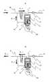
次に、図3及び図4を用いて、ポンプの運転モードの説明をする。
ポンプ吐出量が0%の場合における、吸入及び吐出工程における燃料の流れを図3a及び図3bに示す。図3aが示す吸入工程時では、加圧室12へ燃料が流入すると同時に、吸入副室61から燃料が流出する。このとき、燃料吸入通路10から流入する燃料の流速は、加圧室12への流入速度と、吸入副室61からの流出速度の差となる。一方、図3bが示す吐出工程時では、加圧室12内の燃料は全て低圧側へ流出すると同時に、吸入副室61へ燃料が流入する。このとき、燃料吸入通路10へ流出する燃料の流速は、加圧室12からの流出速度と吸入副室61への流入速度の差となる。Next, the operation mode of the pump will be described with reference to FIGS. 3 and 4.
The fuel flow in the suction and discharge process when the pump discharge amount is 0% is shown in FIGS. 3a and 3b. In the suction process shown in FIG. 3 a, the fuel flows out from the
ポンプ吐出量が100%の場合における、吸入及び吐出工程の燃料の流れを図4a及び図4bに示す。図4aが示す吸入工程時は、0%吐出と同様、加圧室12へ燃料が流入すると同時に、吸入副室61から燃料が流出する。一方、図4bに示す吐出工程時では、加圧室12内の燃料は吐出通路11側へ吐出される。そのため、低圧側では吸入副室61が吸入する燃料のみが、燃料吸入通路10から流出する。 FIGS. 4a and 4b show the fuel flow in the suction and discharge processes when the pump discharge amount is 100%. At the time of the suction process shown in FIG. 4a, the fuel flows out from the
次に、数式を用いて最も効果的に低圧配管側の脈動を低減できる加圧室12と吸入副室61の押しのけ容積について述べる。すなわち、流速差ΔQが最小となる容積の関係について説明する。前記のとおり、燃料吸入流路10内の流速は、ポンプの運転モードによって異なる。本発明の高圧燃料ポンプは可変容量式であるため、それぞれの運転モードを考慮した最適値が存在する。 Next, the displacement volume of the pressurizing
プランジャ2の大径部の断面積をA1、小径部分の断面積をA2とすると、吸入副室61の押しのけ容積に寄与する断面積A3は、(数1)となる。Assuming that the cross-sectional area of the large-diameter portion of the

吸入工程時における燃料吸入通路10に流入する燃料の最大流速Qinは、吸入工程時のプランジャ2の最大速度をvとすると、(数2)により表される。The maximum flow rate Qin of the fuel flowing into the
吐出工程時における燃料吸入通路10に流入する燃料の最大流速Qoutは、吐出モードにより異なる。0%吐出モードにおいては、吐出工程時のプランジャ2の最大速度をvとすると、(数3)により表される。Maximum flow rate Qout of the fuel flowing into the
一方、100%吐出モードにおいては、吐出工程時に燃料吸入通路10に流入する燃料の最大流速Qoutは、(数4)により表される。On the other hand, in the 100% discharge mode, maximum flow rateQ out of the fuel flowing into the
燃料吸入通路10に流入・流出する燃料の流速差ΔQは、QinとQoutの最大値から最小値を引くことによって求めることができる。0%吐出モードにおける流速差ΔQは、(数3)から(数2)を引くことにより求められる。The flow velocity difference ΔQ of the fuel flowing into and out of the
また、100%吐出モードにおける流速差ΔQは、(式2)と(式4)のいずれか絶対値の大きい方となる。 Further, the flow rate difference ΔQ in the 100% discharge mode is the larger one of (Equation 2) and (Equation 4).
図5に、0%吐出モードにおける流速差(数5)、100%吐出モードにおける流速差(数6)、及びこれらの最大値を重ね合わせたグラフを示す。0%吐出の場合、ΔQは容積比(A3/A1)が1に近づくほど小さくなる傾向にある。一方、100%吐出の場合には、ΔQは容積比(A3/A1)が0.5の時に最小値をとる。すなわち、ある容積比(A3/A1)で100%吐出モードのΔQを小さくしたとしても、0%吐出モードまでは小さくならない場合もあることがわかる。0%吐出から100%吐出の全域においてΔQが最小となる容積比(A3/A1)を検討する場合、(数5)と(数6)の最大値の最小値を求める必要がある。すなわち、(数7)の最小値を求めることとなる。FIG. 5 shows a graph in which the flow rate difference in the 0% discharge mode (Equation 5), the flow rate difference in the 100% discharge mode (Equation 6), and the maximum values thereof are superimposed. In the case of 0% ejection, ΔQ tends to decrease as the volume ratio (A3 / A1 ) approaches 1. On the other hand, in the case of 100% ejection, ΔQ takes the minimum value when the volume ratio (A3 / A1 ) is 0.5. That is, it can be seen that even if ΔQ of the 100% discharge mode is reduced at a certain volume ratio (A3 / A1 ), the 0% discharge mode may not be reduced. When examining the volume ratio (A3 / A1 ) that minimizes ΔQ in the entire region from 0% discharge to 100% discharge, it is necessary to obtain the minimum value of the maximum values of (Equation 5) and (Equation 6). That is, the minimum value of (Expression 7) is obtained.
上記(数7)の最小値は、図5において太い実線が折れ曲がった位置、すなわち、容積比(A3/A1)=2/3においてΔQを極小とする。すなわち、吸入副室61と加圧室12の押しのけ容積の比を2:3とすると、理論上、低圧配管の圧力脈動を最小とすることができる。The minimum value of the above (Expression 7) makes ΔQ minimum at the position where the thick solid line is bent in FIG. 5, that is, at the volume ratio (A3 / A1 ) = 2/3. That is, when the ratio of the displacement volume of the
そして、この理論上の最適点において、小径部分の断面積A2は、(数1)により、
もっとも、上記した比率は理論上導かれる数値であるから、概ねこの値であれば最小値に近い脈動特性が得られるため、必ずしも正確にこの値とする必要はない。吸入副室61と加圧室12の押しのけ容積の比については、2:3の時に最適であると記載したが、概ね2:3であれば最小値に近い脈動特性が得られるし、同様に、プランジャ2の小径部分と大径部分の断面積比についても、概ね1:3であれば、最小値に近い脈動が得られる。 However, since the above ratio is a numerical value that is theoretically derived, if this value is approximately this value, a pulsation characteristic close to the minimum value can be obtained, and therefore it is not always necessary to accurately set this value. The ratio of the displacement volume of the
最後に、図6を用いて本発明を適用した別の実施形態である可変容量式燃料ポンプの詳細構造を説明する。プランジャ2cはその大径部2eにおいてシリンダ63cによって摺動可能に保持されている。加圧室12cは、ポンプボディ68c、プランジャ2cなどにより形成される。シリンダ63cは、シリンダホルダ64cによってポンプボディ68cに押圧されている。シリンダホルダ64cは、フランジホルダ66cによってシリンダホルダ64cに押圧されている。フランジホルダ64cは、ねじ又は圧入によってポンプボディ68cに固定され、フランジホルダ64cを押圧する。プランジャ2cの小径部2dにはシール部材60cが摺接されており、シール部材60cはシリンダホルダ64cに固定されている。シリンダホルダ64c、プランジャ小径部2d、シール部材60cにより吸入副室61cが形成される。吸入副室61c内の燃料は、シール部材60cとOリング67cによって外部漏れをシールされている。吸入副室61cは連通流路62cを通じて燃料吸入通路10cと連通する。連通流路62cの一部には、シリンダ63cとシリンダホルダ64cの一部によって絞り部70cが形成される。燃料吸入通路10cと加圧室12cの間には脈動吸収室69cが設けられ、そこにはアキュムレータ65cが設置されている。脈動吸収室69cと加圧室12cの間には燃料の流通方向を制限する吸入弁5cが設けられている。この吸入弁5cは、アクチュエータ8cによってその開弁・閉弁動作が制御される。また、図示6では省略されているが、加圧室12cと吐出通路の間に吐出弁が設けられている。 Finally, the detailed structure of a variable displacement fuel pump according to another embodiment to which the present invention is applied will be described with reference to FIG. The
プランジャ2cが往復動作すると、吸入副室61c内の容積が増減し、連通流路62cを通じて燃料が脈動吸収室69cに流入・流出される。一方、加圧室12cからも脈動吸収室へ燃料が流入・流出される。脈動吸収室12c内でこれらの燃料流出入が差し引かれ、余剰分が圧力脈動発生に寄与するが、アキュムレータ65cによって脈動は低減される。燃料吸入通路10cの途中にオリフィスやチョークなどを設けると、脈動吸収室69c内の圧力脈動を上流側の配管(低圧配管)へ伝播することを低減できるので、更に望ましい。 When the
以上の説明から理解されるように、本実施例に係るプランジャ式高圧燃料ポンプは、加圧室とは反対側に、プランジャが往復運動することにより容積が変化する吸入副室を設け、かつ吸入副室と吸入側管路を連通する通路を備え、望ましくは吸入副室と加圧室の容積比を2:3とすることにより、加圧室と吸入通路の間で吸入又は吐出される燃料を、吸入副室と吸入通路の間で吐出又は吸入される燃料が効果的に相殺することにより、吸入通路に連通する低圧配管の圧力脈動を低減することができる。
本実施例によれば、ポンプハウジング内に設けられたシリンダと、シリンダ内に摺動可能に設けられるものであってかつ回転するカムに従って往復運動するプランジャと、プランジャ及びシリンダにより形成される加圧室と、加圧室と吸入側管路の間を開閉する吸入弁と、加圧室と吐出側管路の間を開閉する吐出弁と、吸入弁の開閉を制御するアクチュエータとを備えたプランジャ式高圧燃料ポンプであって、プランジャの加圧室とは反対側に、プランジャが往復運動することにより容積が変化する吸入副室を設け、吸入副室と前記吸入側管路を連通する通路を備える。こうすることにより、プランジャが往復運動して加圧室へ燃料が吸入・吐出されると同時に、吸入副室へ燃料が吐出・吸入されるため、流量の変動を低減する共に低圧配管の圧力脈動を低減する。
更に望ましくは、前記プランジャ式高圧燃料ポンプにおいて、吸入副室と加圧室の押しのけ容積の比が概ね2:3とするものである。詳細は後述するが、こうすることにより、ポンプの運転モード全域において、低圧配管への燃料流速が理論上最小化され、低圧配管の圧力脈動を効果的に低減できる。
または、ポンプハウジング内に設けられたシリンダと、シリンダ内に摺動可能に設けられるものであってかつ回転するカムに従って往復運動するプランジャと、前記プランジャ及び前記シリンダにより形成される加圧室と、前記加圧室と吸入側管路の間を開閉する吸入弁と、前記加圧室と吐出側管路の間を開閉する吐出弁と、前記吸入弁の開閉を操作するアクチュエータとを備えたプランジャ式高圧燃料ポンプであって、前記プランジャは大径部と小径部から形成されて該小径部には摺接するシール部材を設け、前記プランジャの該小径部と該シール部材により形成される吸入副室を設け、該吸入副室と前記吸入側管路との間を連通する通路を備えたプランジャ式高圧燃料ポンプとする。こうすることにより、前記の吸入副室を、プランジャの小径部とシール部材により構成することができ、かつ、シール部材の径を小型化することにより、シール部材からの漏れ量を低減できる。
更に望ましくは、プランジャ式高圧燃料ポンプにおいて、プランジャの小径部と大径部の断面積の比が概ね1:3となるようにするものである。こうすることにより、吸入副室と加圧室の押しのけ容積の比が概ね2:3となって、前記と同じく、低圧配管の圧力脈動を効果的に低減することができる。
更に望ましくは、吸入副室と吸入側管路との間を連通する通路内にオリフィスなどの絞り部を設けたものである。こうすることにより、ポンプの吐出工程中において、吸入副室内に燃料が抜けにくくなり、吸入副室内の圧力が低くなる。そうすると、次の吸入工程において、プランジャが吸入副室側へ吸い寄せられてジャンピングしにくくなる。
更に望ましくは、吸入側管路と吸入弁の間にアキュムレータを設けたものである。こうすることにより、前述のごとく吸入側管路へ出入りする流量変動が低減され、かつ、アキュムレータが吸入側管路へ伝播する前に圧力脈動を吸収することができる。
以上のごとく構成されたプランジャ式高圧燃料ポンプでは、加圧室から低圧配管へ吸入・吐出する燃料の量を、吸入副室へ吐出・吸入する燃料が効果的に相殺することにより、低圧配管の圧力脈動を低減することができる。
本実施例によれば、エンジン負荷が低い状態から高い状態、すなわちポンプの燃料吐出量が少ない状態から多い状態まで、全域において脈動低減に有効である。低圧配管の圧力脈動はエンジン回転数によって共振点が存在することもあるが、起振力となるポンプ内部からの流量変動を最小に抑えることにより、いかなる状況でも圧力脈動を低減することができる。また、ポンプ内部の流量変動が小さくなるため、アキュムレータの性能を下げる余裕もできる。すなわち、アキュムレータの小型化、簡素化を図ることもできる。また、プランジャの小径部で燃料シールを行うため、大径部で燃料シールする場合と比べてシール面積が小さくなるので燃料リーク量を減らす効果もある。本実施例では、吸入副室と加圧室の押しのけ容積の比率を2:3としたが、概ねそれに近い値であれば同等の脈動低減効果を得ることができる。As can be understood from the above description, the plunger type high-pressure fuel pump according to thisembodiment is provided with a suction sub chamber whose volume is changed by the reciprocating movement of the plunger on the side opposite to the pressurizing chamber, and A fuel that is provided with a passage that communicates the sub chamber and the suction side pipe line, and preferably has a volume ratio of the suction sub chamber and the pressurization chamber of 2: 3, so that the fuel is sucked or discharged between the pressurization chamber and the suction passage. By effectively canceling out the fuel discharged or sucked between the suction sub chamber and the suction passage, the pressure pulsation of the low-pressure pipe communicating with the suction passage can be reduced.
According to the present embodiment, a cylinder provided in the pump housing, a plunger slidably provided in the cylinder and reciprocating according to a rotating cam, and a pressure formed by the plunger and the cylinder Plunger including a chamber, a suction valve that opens and closes between the pressurizing chamber and the suction side pipe, a discharge valve that opens and closes between the pressurization chamber and the discharge side pipe, and an actuator that controls opening and closing of the suction valve The high-pressure fuel pump is provided with a suction sub chamber whose volume changes as the plunger reciprocates on the side opposite to the pressurization chamber of the plunger, and a passage that connects the suction sub chamber and the suction side pipe line. Prepare. By doing so, the plunger reciprocates and the fuel is sucked and discharged into the pressurizing chamber, and at the same time, the fuel is discharged and sucked into the suction subchamber. Reduce.
More preferably, in the plunger type high-pressure fuel pump, the ratio of the displacement volume between the suction sub chamber and the pressurizing chamber is approximately 2: 3. Although details will be described later, by doing so, the fuel flow velocity to the low-pressure pipe is theoretically minimized in the entire operation mode of the pump, and the pressure pulsation of the low-pressure pipe can be effectively reduced.
Alternatively, a cylinder provided in the pump housing, a plunger that is slidable in the cylinder and reciprocates according to a rotating cam, and a pressure chamber formed by the plunger and the cylinder, Plunger comprising: a suction valve that opens and closes between the pressurizing chamber and the suction side conduit; a discharge valve that opens and closes between the pressurization chamber and the discharge side conduit; and an actuator that operates to open and close the suction valve A high pressure fuel pump, wherein the plunger is formed of a large diameter portion and a small diameter portion, and a seal member is provided in sliding contact with the small diameter portion, and a suction subchamber formed by the small diameter portion of the plunger and the seal member And a plunger type high-pressure fuel pump having a passage communicating between the suction sub chamber and the suction side pipe. In this way, the suction sub chamber can be constituted by the small diameter portion of the plunger and the seal member, and the amount of leakage from the seal member can be reduced by reducing the diameter of the seal member.
More preferably, in the plunger type high-pressure fuel pump, the ratio of the cross-sectional area of the small diameter portion and the large diameter portion of the plunger is approximately 1: 3. By doing so, the ratio of the displacement volume of the suction sub chamber and the pressurizing chamber becomes approximately 2: 3, and the pressure pulsation of the low pressure pipe can be effectively reduced as described above.
More preferably, a throttle portion such as an orifice is provided in a passage communicating between the suction sub chamber and the suction side pipe line. This makes it difficult for fuel to escape into the suction subchamber during the pump discharge process, and lowers the pressure in the suction subchamber. Then, in the next inhalation step, the plunger is sucked toward the inhalation subchamber side and is difficult to jump.
More preferably, an accumulator is provided between the suction side pipe line and the suction valve. By doing so, the flow rate fluctuation entering and exiting the suction side conduit as described above is reduced, and the pressure pulsation can be absorbed before the accumulator propagates to the suction side conduit.
In the plunger type high-pressure fuel pump configured as described above, the amount of fuel sucked and discharged from the pressurizing chamber to the low-pressure pipe is effectively offset by the fuel discharged and sucked into the suction sub-chamber. Pressure pulsation can be reduced.
According to the present embodiment, it is effective in reducing pulsation in the entire region from a state where the engine load is low to a high state, that is, a state where the fuel discharge amount of the pump is small to a large state. Although the pressure pulsation of the low-pressure pipe may have a resonance point depending on the engine speed, the pressure pulsation can be reduced in any situation by minimizing the flow rate fluctuation from the inside of the pump, which becomes the excitation force. In addition, since the flow rate fluctuation inside the pump is reduced, there is a margin for reducing the performance of the accumulator. That is, the accumulator can be reduced in size and simplified. Further, since the fuel seal is performed at the small diameter portion of the plunger, the seal area is reduced as compared with the case where the fuel seal is performed at the large diameter portion. In this embodiment, the ratio of the displacement volume between the suction sub chamber and the pressurizing chamber is set to 2: 3. However, an equivalent pulsation reduction effect can be obtained if the ratio is substantially close to that.
1 高圧燃料ポンプ(本体)
2 プランジャ
2a プランジャ小径部
2b プランジャ大径部
3 タペット
5 吸入弁
6 吐出弁
8 電磁アクチュエータ
10 (燃料)吸入通路
11 吐出通路
12 加圧室
61 吸入副室
62 連通流路
90 ソレノイドコイル
91 ロッド
92 ばね
100 カム1 High-pressure fuel pump (main unit)
2
Claims (8)
Translated fromJapanese回転するカムに従って往復運動するプランジャと、
前記加圧室と吸入側管路の間を開閉する吸入弁と、
前記加圧室と吐出側管路の間を開閉する吐出弁と、
前記吸入弁の開閉を制御するアクチュエータとを備えたプランジャ式高圧燃料ポンプであって、
前記プランジャの前記加圧室とは反対側に、前記プランジャが往復運動することにより
容積が変化する吸入副室を設け、
前記吸入弁と前記吸入側管路との間の燃料吸入通路であって前記ポンプハウジングに設けられた燃料吸入通路にアキュムレータを設け、
前記吸入副室と前記アキュムレータが設けられた前記燃料吸入通路とを連通する連通流路を備えたことを特徴とするプランジャ式高圧燃料ポンプ。Apressurizing chamber provided in the pump housing;
A plunger reciprocates in accordance with therotation cam,
A suction valve for opening and closing between thefront Symbol pressurizing chamber suction side conduit,
A discharge valve for opening and closing between the pressurizing chamber and the discharge side pipe line;
A plunger-type high-pressure fuel pump comprising an actuator for controlling opening and closing of the suction valve,
Provided on the opposite side of the plunger from the pressurizing chamber is a suction subchamber whose volume changes as the plunger reciprocates,
An accumulator is provided in a fuel suction passage between the suction valve and the suction side pipe and provided in the pump housing;
Plunger type high-pressure fuel pump, wherein theaccumulator and the suction sub-chamberis provided with acommunicationpassage for communicatingthe fuel intakepassage pathprovided.
求項1に記載のプランジャ式高圧燃料ポンプ。2. The plunger type high-pressure fuel pump according to claim 1, wherein a ratio of displacement volumes of the suction sub chamber and the pressurizing chamber is approximately 2: 3.
回転するカムに従って往復運動するプランジャと、
前記加圧室と吸入側管路の間を開閉する吸入弁と、
前記加圧室と吐出側管路の間を開閉する吐出弁と、
前記吸入弁の開閉を制御するアクチュエータとを備えたプランジャ式高圧燃料ポンプであって、
前記プランジャは大径部と小径部から形成されて該小径部には当該プランジャの外周に摺接するシール部材を設け、
前記プランジャの前記小径部と前記シール部材により形成される吸入副室を設け、
前記吸入弁と前記吸入側管路との間の燃料吸入通路であって前記ポンプハウジングに設けられた燃料吸入通路にアキュムレータを設け、
前記吸入副室と前記アキュムレータが設けられた前記燃料吸入通路とを連通する連通流路を備えたことを特徴とするプランジャ式高圧燃料ポンプ。Apressurizing chamber provided in the pump housing;
A plunger reciprocates in accordance with therotation cam,
A suction valve for opening and closing between thefront Symbol pressurizing chamber suction side conduit,
A discharge valve for opening and closing between the pressurizing chamber and the discharge side pipe line;
A plunger-type high-pressure fuel pump comprising an actuator for controlling opening and closing of the suction valve,
The plunger is formed of a large-diameter portion and a small-diameter portion, and the small-diameter portion is provided with a seal member thatis in sliding contact withthe outer periphery of the plunger ,
The intake sub-chamber formed bythe sealing member andthe small diameter portion of the plunger is provided,
An accumulator is provided in a fuel suction passage between the suction valve and the suction side pipe and provided in the pump housing;
Plunger type high-pressure fuel pump, wherein theaccumulator and the suction sub-chamberis provided with acommunicationpassage for communicatingthe fuel intakepassage pathprovided.
項3に記載のプランジャ式高圧燃料ポンプ。The plunger type high-pressure fuel pump according to claim 3, wherein a ratio of a cross-sectional area between the small diameter portion and the large diameter portion of the plunger is approximately 1: 3.
Priority Applications (1)
| Application Number | Priority Date | Filing Date | Title |
|---|---|---|---|
| JP2006172934AJP4648254B2 (en) | 2006-06-22 | 2006-06-22 | High pressure fuel pump |
Applications Claiming Priority (1)
| Application Number | Priority Date | Filing Date | Title |
|---|---|---|---|
| JP2006172934AJP4648254B2 (en) | 2006-06-22 | 2006-06-22 | High pressure fuel pump |
Related Child Applications (1)
| Application Number | Title | Priority Date | Filing Date |
|---|---|---|---|
| JP2010124888ADivisionJP4995941B2 (en) | 2010-05-31 | 2010-05-31 | High pressure fuel pump |
Publications (2)
| Publication Number | Publication Date |
|---|---|
| JP2008002361A JP2008002361A (en) | 2008-01-10 |
| JP4648254B2true JP4648254B2 (en) | 2011-03-09 |
Family
ID=39006949
Family Applications (1)
| Application Number | Title | Priority Date | Filing Date |
|---|---|---|---|
| JP2006172934AActiveJP4648254B2 (en) | 2006-06-22 | 2006-06-22 | High pressure fuel pump |
Country Status (1)
| Country | Link |
|---|---|
| JP (1) | JP4648254B2 (en) |
Families Citing this family (17)
| Publication number | Priority date | Publication date | Assignee | Title |
|---|---|---|---|---|
| JP5002523B2 (en)* | 2008-04-25 | 2012-08-15 | 日立オートモティブシステムズ株式会社 | Fuel pressure pulsation reduction mechanism and high-pressure fuel supply pump for internal combustion engine equipped with the same |
| JP5478051B2 (en)* | 2008-10-30 | 2014-04-23 | 日立オートモティブシステムズ株式会社 | High pressure fuel supply pump |
| JP5017233B2 (en)* | 2008-10-30 | 2012-09-05 | 日立オートモティブシステムズ株式会社 | High pressure fuel pump |
| JP4736142B2 (en)* | 2009-02-18 | 2011-07-27 | 株式会社デンソー | High pressure pump |
| EP2410167B1 (en) | 2009-03-17 | 2013-08-28 | Toyota Jidosha Kabushiki Kaisha | Pulsation damper |
| JP4941688B2 (en)* | 2009-11-09 | 2012-05-30 | 株式会社デンソー | High pressure pump |
| JP5401360B2 (en) | 2010-02-26 | 2014-01-29 | 日立オートモティブシステムズ株式会社 | High pressure fuel supply pump |
| JP5136919B2 (en) | 2010-04-08 | 2013-02-06 | 株式会社デンソー | High pressure pump |
| JP5909502B2 (en)* | 2011-11-30 | 2016-04-26 | 日立オートモティブシステムズ株式会社 | High pressure fuel supply pump |
| JP5625016B2 (en)* | 2012-06-04 | 2014-11-12 | 日立オートモティブシステムズ株式会社 | High pressure fuel pump |
| CN103869030B (en)* | 2012-12-18 | 2016-12-28 | 北京普源精仪科技有限责任公司 | A kind of chromatograph of liquid with plunger pump in series and control method thereof |
| CN103266973A (en)* | 2013-05-31 | 2013-08-28 | 龙口龙泵燃油喷射有限公司 | Radial high-pressure oil feed pump of high-speed diesel engine |
| KR101434626B1 (en)* | 2014-01-09 | 2014-08-27 | 주식회사 신행 | Booster pump for high viscosity liquid transfer |
| WO2016056333A1 (en)* | 2014-10-09 | 2016-04-14 | 日立オートモティブシステムズ株式会社 | High pressure fuel supply pump |
| JP2020128700A (en)* | 2017-06-09 | 2020-08-27 | 日立オートモティブシステムズ株式会社 | High-pressure fuel pump |
| DE102018217644A1 (en)* | 2018-10-15 | 2020-04-16 | Hyundai Motor Company | HIGH PRESSURE PUMP AND METHOD FOR COMPRESSING A FLUID |
| DE102019130684A1 (en)* | 2019-11-14 | 2021-05-20 | Man Energy Solutions Se | Piston pump |
Family Cites Families (6)
| Publication number | Priority date | Publication date | Assignee | Title |
|---|---|---|---|---|
| JPH09250427A (en)* | 1996-03-15 | 1997-09-22 | Zexel Corp | Fuel injection pump |
| JPH10299609A (en)* | 1997-04-18 | 1998-11-10 | Zexel Corp | Pulsation reducing damper |
| JP3428443B2 (en)* | 1998-06-29 | 2003-07-22 | 株式会社日立製作所 | Variable flow high pressure fuel pump and fuel supply control method |
| JP2001248517A (en)* | 2000-03-01 | 2001-09-14 | Mitsubishi Electric Corp | Variable discharge fuel supply device |
| DE10134066A1 (en)* | 2001-07-13 | 2003-02-06 | Bosch Gmbh Robert | Fuel pump, in particular high-pressure fuel pump for a fuel system of an internal combustion engine with gasoline direct injection |
| JP4215000B2 (en)* | 2005-01-19 | 2009-01-28 | 株式会社デンソー | High pressure pump |
- 2006
- 2006-06-22JPJP2006172934Apatent/JP4648254B2/enactiveActive
Also Published As
| Publication number | Publication date |
|---|---|
| JP2008002361A (en) | 2008-01-10 |
Similar Documents
| Publication | Publication Date | Title |
|---|---|---|
| JP4648254B2 (en) | High pressure fuel pump | |
| JP4701227B2 (en) | Plunger high pressure fuel pump | |
| JP4165572B2 (en) | Fuel supply device for internal combustion engine | |
| CN100540880C (en) | Fuel injection system capable of monitoring abnormal pressure at the inlet of fuel pump | |
| JP4600399B2 (en) | Control device for internal combustion engine | |
| CN115698495B (en) | Solenoid valve control device | |
| JP5202123B2 (en) | Fuel supply control device for internal combustion engine | |
| JP4455470B2 (en) | Controller for high pressure fuel pump and normally closed solenoid valve of high pressure fuel pump | |
| US6901912B1 (en) | Variable delivery fuel supply device | |
| JP5401579B2 (en) | High pressure fuel pump | |
| JP4995941B2 (en) | High pressure fuel pump | |
| CN102933831B (en) | Pressure regulator | |
| JP4404056B2 (en) | Fuel injection device for internal combustion engine | |
| JP2015063921A (en) | Fuel injection device for internal combustion engine | |
| JP2004084560A (en) | Fuel supply device for internal combustion engine | |
| WO2023026514A1 (en) | Solenoid valve control device | |
| JP2006017111A (en) | Device for adjusting pressure/flow in internal combustion engine fuel injection device | |
| JP5470363B2 (en) | High pressure fuel pump control device for internal combustion engine | |
| JP2018003610A (en) | Fuel pressure control device of internal combustion engine | |
| JP2007120356A (en) | Internal combustion engine fuel piping structure | |
| JP2007077967A (en) | Fuel injection device | |
| JP6015471B2 (en) | Fuel supply device | |
| JP3172607U (en) | Apparatus for regulating pressure / flow in an internal combustion engine fuel injector | |
| WO2024127634A1 (en) | Control device for internal combustion engine | |
| JP4969611B2 (en) | High pressure fuel pump control device for internal combustion engine |
Legal Events
| Date | Code | Title | Description |
|---|---|---|---|
| A621 | Written request for application examination | Free format text:JAPANESE INTERMEDIATE CODE: A621 Effective date:20081202 | |
| A711 | Notification of change in applicant | Free format text:JAPANESE INTERMEDIATE CODE: A712 Effective date:20100115 | |
| A977 | Report on retrieval | Free format text:JAPANESE INTERMEDIATE CODE: A971007 Effective date:20100325 | |
| A131 | Notification of reasons for refusal | Free format text:JAPANESE INTERMEDIATE CODE: A131 Effective date:20100330 | |
| A521 | Request for written amendment filed | Free format text:JAPANESE INTERMEDIATE CODE: A523 Effective date:20100531 | |
| TRDD | Decision of grant or rejection written | ||
| A01 | Written decision to grant a patent or to grant a registration (utility model) | Free format text:JAPANESE INTERMEDIATE CODE: A01 Effective date:20101207 | |
| A01 | Written decision to grant a patent or to grant a registration (utility model) | Free format text:JAPANESE INTERMEDIATE CODE: A01 | |
| A61 | First payment of annual fees (during grant procedure) | Free format text:JAPANESE INTERMEDIATE CODE: A61 Effective date:20101209 | |
| FPAY | Renewal fee payment (event date is renewal date of database) | Free format text:PAYMENT UNTIL: 20131217 Year of fee payment:3 | |
| R150 | Certificate of patent or registration of utility model | Ref document number:4648254 Country of ref document:JP Free format text:JAPANESE INTERMEDIATE CODE: R150 Free format text:JAPANESE INTERMEDIATE CODE: R150 | |
| S533 | Written request for registration of change of name | Free format text:JAPANESE INTERMEDIATE CODE: R313533 | |
| R350 | Written notification of registration of transfer | Free format text:JAPANESE INTERMEDIATE CODE: R350 | |
| R250 | Receipt of annual fees | Free format text:JAPANESE INTERMEDIATE CODE: R250 | |
| R250 | Receipt of annual fees | Free format text:JAPANESE INTERMEDIATE CODE: R250 |