JP4647799B2 - Method for manufacturing liquid filling container - Google Patents
Method for manufacturing liquid filling containerDownload PDFInfo
- Publication number
- JP4647799B2 JP4647799B2JP2001016029AJP2001016029AJP4647799B2JP 4647799 B2JP4647799 B2JP 4647799B2JP 2001016029 AJP2001016029 AJP 2001016029AJP 2001016029 AJP2001016029 AJP 2001016029AJP 4647799 B2JP4647799 B2JP 4647799B2
- Authority
- JP
- Japan
- Prior art keywords
- neck
- curl
- container
- cylindrical body
- annular base
- Prior art date
- Legal status (The legal status is an assumption and is not a legal conclusion. Google has not performed a legal analysis and makes no representation as to the accuracy of the status listed.)
- Expired - Lifetime
Links
Images


Classifications
- B—PERFORMING OPERATIONS; TRANSPORTING
- B65—CONVEYING; PACKING; STORING; HANDLING THIN OR FILAMENTARY MATERIAL
- B65D—CONTAINERS FOR STORAGE OR TRANSPORT OF ARTICLES OR MATERIALS, e.g. BAGS, BARRELS, BOTTLES, BOXES, CANS, CARTONS, CRATES, DRUMS, JARS, TANKS, HOPPERS, FORWARDING CONTAINERS; ACCESSORIES, CLOSURES, OR FITTINGS THEREFOR; PACKAGING ELEMENTS; PACKAGES
- B65D1/00—Rigid or semi-rigid containers having bodies formed in one piece, e.g. by casting metallic material, by moulding plastics, by blowing vitreous material, by throwing ceramic material, by moulding pulped fibrous material or by deep-drawing operations performed on sheet material
- B65D1/40—Details of walls
- B65D1/42—Reinforcing or strengthening parts or members
- B65D1/46—Local reinforcements, e.g. adjacent closures
- B—PERFORMING OPERATIONS; TRANSPORTING
- B65—CONVEYING; PACKING; STORING; HANDLING THIN OR FILAMENTARY MATERIAL
- B65D—CONTAINERS FOR STORAGE OR TRANSPORT OF ARTICLES OR MATERIALS, e.g. BAGS, BARRELS, BOTTLES, BOXES, CANS, CARTONS, CRATES, DRUMS, JARS, TANKS, HOPPERS, FORWARDING CONTAINERS; ACCESSORIES, CLOSURES, OR FITTINGS THEREFOR; PACKAGING ELEMENTS; PACKAGES
- B65D1/00—Rigid or semi-rigid containers having bodies formed in one piece, e.g. by casting metallic material, by moulding plastics, by blowing vitreous material, by throwing ceramic material, by moulding pulped fibrous material or by deep-drawing operations performed on sheet material
- B65D1/40—Details of walls
- B65D1/42—Reinforcing or strengthening parts or members
- B65D1/48—Reinforcements of dissimilar materials, e.g. metal frames in plastic walls
- Y—GENERAL TAGGING OF NEW TECHNOLOGICAL DEVELOPMENTS; GENERAL TAGGING OF CROSS-SECTIONAL TECHNOLOGIES SPANNING OVER SEVERAL SECTIONS OF THE IPC; TECHNICAL SUBJECTS COVERED BY FORMER USPC CROSS-REFERENCE ART COLLECTIONS [XRACs] AND DIGESTS
- Y02—TECHNOLOGIES OR APPLICATIONS FOR MITIGATION OR ADAPTATION AGAINST CLIMATE CHANGE
- Y02W—CLIMATE CHANGE MITIGATION TECHNOLOGIES RELATED TO WASTEWATER TREATMENT OR WASTE MANAGEMENT
- Y02W30/00—Technologies for solid waste management
- Y02W30/50—Reuse, recycling or recovery technologies
- Y02W30/80—Packaging reuse or recycling, e.g. of multilayer packaging
Landscapes
- Engineering & Computer Science (AREA)
- Ceramic Engineering (AREA)
- Mechanical Engineering (AREA)
- Containers Having Bodies Formed In One Piece (AREA)
- Details Of Rigid Or Semi-Rigid Containers (AREA)
Description
Translated fromJapanese【0001】
【発明の属する技術分野】
本発明はヘアリキッド、トニック、育毛剤、乳液、化粧水等の液状物を充填する容器を製造する方法に関する。詳しくは、耐蝕性が良好であり、かつリサイクルし易い液状物充填用容器の製造方法に関する。
【0002】
【従来の技術】
化粧品等の液状物を充填するための容器としては、例えば図6ないし図8に示されるものが知られている。
図6に例示される容器31は、合成樹脂製の容器であり、有底円筒状の胴部32と、その上部に形成された肩部33と円筒状の首部35とを有し、該首部35の外周にはネジ部37が設けられている。
このような容器は、主にヘアリキッド、トニック、育毛剤などが充填され、首部35に吐出量調整用の中栓39が嵌入され、さらに容器口部が、上記ネジ部37に螺合する保護キャップあるいはポンプアッセンブリーで閉止されて使用される。
上記容器と同じ形状で、ガラス製のものもあり、主に乳液、化粧水などの容器として用いられる。
【0003】
【発明が解決しようとする課題】
化粧品等に用いられる液状物充填用容器では、外面のデザイン、材質等によって高級感およびメタリック感を持たせることが望ましいが、上記合成樹脂製容器では、外表面に印刷などを施しても高級感、メタリック感を持たせることが難しい。
また、ガラス製容器では、表面をスリガラス状とすることで高級感を持たせることができるが、メタリック感を持たせるのは難しい。また落下等の衝撃により破損しやすいという問題もある。
このため、高級感、メタリック感を持たせやすく、かつ破損しにくい容器として、金属製のものが用いられている。
【0004】
図7および図8は、金属製容器の例を示すものである。
図7に示す容器41はアルミニウムなどの金属で形成され、有底円筒状の胴部42と、その上部に形成された肩部43と円筒状の首部45とを有し、首部45の外周にはネジ部47が設けられている。容器41の首部45の内周面側にはネジ部47に相当する位置に凹部48が形成されている。通常、容器41内面には、腐蝕防止用の保護塗膜が形成される。
【0005】
図8に示す容器は、特開平9−118345号公報に記載されたもので、ここに示す容器51は、胴部52と肩部53と首部55とを有する金属製の缶部51aと、首部55の外周に取り付けられた合成樹脂製のねじリング58とから構成され、ねじリング58がフランジ54とねじリング胴部58aとを有し、ねじリング胴部58aの外周にはネジ部57が形成され、首部55の開口端部は外方に湾曲してフランジ54を巻き込んでカール部56となっている。
この容器51は、上記合成樹脂製容器、ガラス製容器と同様に、化粧品等の液状物を充填し、ねじリング58に保護キャップ等を螺着することにより閉止して用いることができる。また首部55にフェルト等で形成された筆記部材が取り付けられることによりマジックペンなどの筆記具としても使用可能である。
【0006】
しかしながら、図7に示す金属製容器41では、腐蝕防止用の保護塗膜を首部45の端縁部45aにも形成するのは難しいため、この部分が金属材料が露出した状態となりやすい。このため、この部分が内容液に触れることにより腐蝕が発生したり、内容液が変質することがあった。
また図8に示す容器51では、首部55の開口端部を外方に湾曲させて形成されたカール部56を有するため、端縁部への内容液接触が起こりにくいものの、内容液使用後に、この容器51を再利用する際に、金属製の缶部51aと合成樹脂製のねじリング58とを分別する必要があり、リサイクルの容易性の点で不満があった。
本発明は上記事情に鑑みてなされたもので、耐蝕性に優れ、かつリサイクルが容易な液状物充填用容器を提供することを目的とする。
【0007】
【課題を解決するための手段】
かかる課題を解決するため、
本願請求項1にかかる発明は、呼称JIS1070のアルミニウムインゴット材をインパクト成形することによって有底筒状体(21)を形成し、この有底筒状体(21)を、胴部(2)と、この胴部(2)の上部に形成された肩部(3)と、この肩部(3)の上部に形成された細径の首部(4)とを有するものとし、この首部(4)にネジ部(5)を形成した後、首部(4)の開口端部(4a)を外方に湾曲させカール部(6)を形成する液状物充填用容器の製造方法であって、
前記カール部(6)の形成がカール部形成用治具(23)を用いて行われ、
このカール部形成用治具(23)は、回転可能な環状基材(24)と、この環状基材(24)の内周面に複数個配設され、環状基材(24)の回転軸に対して直交する回転軸を有して回転するカール部形成ローラ(25)と、前記環状基材(24)の回転軸上に配された円柱状の中心部材(26)を有し、
前記カール部形成ローラ(23)は、その基端部が前記環状基材(24)に回転可能に軸支され、その先端部が前記中心部材(26)に回転可能に軸支されているとともに、断面円形の基部(27)と、この基部(27)の先端側に延びる細径とされた首部28を有し、この首部(28)の外周には周方向に沿う断面円弧状の環状凹部(28a)が形成され、
前記中心部材(26)は、その外周径が前記有底筒状体(21)の首部(4)の内周径よりも小さくされたものであり、
前記有底筒状体(21)の首部(4)の開口端部(4a)を前記カール部形成用治具(23)のカール部形成ローラ(25)に、その首部(4)が前記中心部材(26)から離間した状態で、押し当て、前記有底筒状体(21)の首部(4)を前記環状凹部(28a)の内周面に沿って外方に湾曲させてカール部(6)を形成し、この際、前記環状基体(24)を前記有底筒状体(21)の首部(4)に対し周方向に回転させるとともに、前記カール部形成ローラ(25)を回転させながら前記有底筒状体(21)の首部(4)に押し当てることを特徴とする液状物充填用容器の製造方法である。
【0008】
【発明の実施の形態】
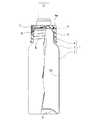
以下、本発明を図面を参照して詳しく説明する。図1および図2は、本発明によって得られた液状物充填用容器の一実施形態を示すものであり、ここに示す液状物充填用容器1は、呼称JIS1070(軟材)のアルミニウムからなり、底部9を有する円筒状の胴部2と、該胴部2の上部に形成された肩部3と、該肩部3の上部に形成された細径の首部4とを有する。胴部2の外径は、30〜55mmとすることができる。
【0009】
首部4は円筒状に形成され、外周にネジ部5が形成されている。
ネジ部5の外径(山部の外径)は、22.5〜23.5mm程度とするのが好ましい。
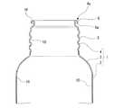
首部4の開口端部4aには、外方に湾曲したカール部6が形成されている。カール部6は、その端縁部6aが下方または内方に向くまで湾曲した状態となっている。
カール部6は、外径が、ネジ部5の外径(好ましくはネジ部5の最小外径、すなわちネジ部5の谷部の外径)より小さくなるように形成するのが好ましい。カール部6の外径は、21.0〜22.0mm程度とするのが好ましい。
また既存のポンプアッセンブリやキャップなどに対する汎用性をもたせるため、ネジ部5やビード部の外径は、上記ポンプアッセンブリ等に合わせて設定するのが好ましい。
【0010】
容器1の内面(胴部2、肩部3、首部4、および底部9の内面)およびカール部6の外面には、全域にわたって保護塗膜10が形成されている。
この保護塗膜10には、エポキシ−フェノール樹脂、ポリアミドイミド樹脂、エポキシ−ユリア樹脂、ビニールオルガノゾル樹脂、ポリエチレン樹脂、フッ素樹脂等の一般的なエアゾール缶に使用される塗料を用いることができる。
なかでも特に、耐蝕性および加工性に優れたポリアミドイミド樹脂を用いるのが好ましい。
【0011】
なお、符号7は、首部4に装着された合成樹脂製のポンプアッセンブリを示す。ポンプアッセンブリ7の内周には、首部4のネジ部5に螺合するネジ部が形成され、ポンプアッセンブリ7をネジ部5に螺着することで容器1の口部を液密に閉止することができるようになっている。
【0012】
次に、上記容器1を製造する場合を例として、本発明の液状物充填用容器の製造方法の一実施形態を図3を参照して説明する。
図3(A)に示すように、アルミニウムインゴット材(JIS1070)を、金型を用いてインパクト成形することによって、有底筒状体21を作製する。
次いで、図3(B)に示すように、必要に応じて有底筒状体21の開口端近傍を切断して筒状体21の高さを調整し、この有底筒状体21の内面を洗浄、乾燥した後、この内面にポリアミドイミド樹脂等を塗装、焼き付けし、保護塗膜10を形成する。
【0013】
次いで、有底筒状体21の外周面にパッケージデザインなどの印刷を施した後、図3(C)に示すように、数段階のプレス加工により有底筒状体21上部を縮径し、肩部3および首部4を形成する。
この際、首部4の開口端を整えるために、首部4の上端近傍を切断しても良い。また後述のカール部6の成形を容易にするために、首部4の開口端部4aを薄肉化してもよい。
【0014】
次いで、図3(D)に示すように、首部4の内周側および外周側に配置されたネジ押圧部材(図示略)により首部4を軸方向に対しほぼ垂直な方向に押圧し曲げ変形させることによって、首部4にネジ部5を形成する。
【0015】
次いで、図3(D)および図3(E)に示すように、開口端部4aを外方に湾曲させ、カール部6を形成する。
カール部6を形成するには、図4に示すカール部形成用治具23を用いることができる。
カール部形成用治具23は、環状基体24と、この環状基体24の内周側に設けられたカール部形成ローラ25と、環状基体24の中心部に設けられた中心部材26とを有する。
カール部形成ローラ25は、断面円形の基部27と、基部27の先端側(環状基体24の内周側)に設けられた細径の首部28とを備えている。この首部28の外周には、周方向に沿って断面円弧状の環状凹部28aが形成されている。
ローラ25は、基部27基端部側および首部28先端側がそれぞれ環状基体24および中心部材26に回転可能に支持され、中心軸25aを以て周方向に回転自在とされている。ローラ25は、軸方向が環状基体24の径方向にほぼ一致するように設けられている。
ローラ25は、環状基体24の周方向に間隔をおいて複数(図示例では6つ)設けられている。
【0016】
このカール部形成用治具23を用いてカール部6を形成するには、次のようにする。
有底筒状体21を固定し、この有底筒状体21の首部4の開口端部4aに、カール部形成ローラ25を押し当てた状態で、環状基体24を首部4に対し周方向に回転させる。
これによって、カール部形成ローラ25は回転しながら首部4の周方向に移動し、この過程で、開口端部4aは、全周にわたって環状凹部28a内周面に沿って徐々に押し広げられて外方に湾曲し、カール部6が形成される。
この際、ローラ25は自身の周方向に回転(自転)しつつ首部4に当接する。このため、ローラ25と首部4との間の摩擦が低減され、カール部形成用治具23をスムーズに首部周方向に回転させることができる。
このように、カール部形成用治具23を周方向に回転させつつ開口端部4aを湾曲させるため、首部4に加えられる縦方向(首部4の軸方向)の力が周方向に均一化され、局部的に首部4に大きな力が加えられるのを防ぐことができる。このため、比較的硬度が低い材料であるアルミニウム(JIS1070)を用いているにもかかわらず、ネジ部5の座屈変形が起こりにくくなる。
以上の工程を経て図1および図2に示す容器1を得る。
【0017】
本実施形態の液状物充填用容器1にあっては、首部4の開口端部4aが外方に湾曲して形成されたカール部6を有するので、端縁部6aにおいて保護塗膜10の形成が不十分となり金属材料が露出した場合でも、この端縁部6aが容器1内の内容液に接するのを防ぐことができる。
従って、内容液によりこの部分が腐食するのを未然に防ぎ、容器1の耐蝕性を高めることができる。
また内容液が、容器1の材料である金属との接触により変質が生じ得るものである場合でも、この内容液の変質を防ぎ、内容液の香りなどが変化するのを防止することができる。
【0018】
また容器1は単一の材料(アルミニウム(JIS1070)のみ)からなるものであるので、使用後は、分解することなくそのまま金属材料として再利用が可能である。従って、リサイクルが容易である。
また金属製であるため、高級感およびメタリック感を持たせやすい。また衝撃が加わっても破損しにくい。
【0019】
また、カール部6を、その外径が、ネジ部5の外径より小さくなるよう形成することによって、ポンプアッセンブリ7を首部4に装着する際に、ポンプアッセンブリ7がカール部6にぶつかることにより装着が妨害されることがなく、装着の際の操作性を向上させることができる。従って、取扱いが容易となる。
【0020】
また保護塗膜10に、加工性、耐久性に優れたポリアミドイミド系樹脂を用いることによって、保護塗膜10のひび割れや剥離を防ぎ、内容液による容器1の腐蝕を防ぐことができる。
【0021】
また、上記実施形態の製造方法によれば、首部4にネジ部5を形成した後に、首部4の開口端部4aを外方に湾曲させカール部6を形成するので、ネジ部5の形成に伴ってカール部6が変形するのを防ぐことができる。
このため、カール部6の変形によりカール部6とポンプアッセンブリ7との間に隙間が生じることにより容器1のシール性が低下するのを未然に防ぐことができる。
これに対し、カール部を形成した後で首部にネジ部を形成する場合には、ネジ部を形成するにあたり、ネジ押圧部材により首部を押圧し曲げ変形させるに伴って、ネジ部上方の部分の首部に下方への引張力が加わるため、平滑な天面を有するカール部を形成することが難しく、カール部に局部的な凹みが形成される場合がある。このため、この容器に装着されるキャップ(ポンプアッセンブリなど)と、カール部との間に隙間が生じ、容器のシール性が低下することがある。
【0022】
また、上記方法によれば、環状基体24を周方向に回転させるとともに、カール部形成ローラ25を回転させながら首部4に押し当てることによって首部4を湾曲させるため、カール部形成用治具23の首部周方向回転をスムーズに行わせ、首部4に加えられる力を周方向に均一にすることができる。このため、カール部6の変形を防ぎ、その形状を周方向に均一化し、平滑な天面を有するカール部6を形成することができる。
よって、ポンプアッセンブリ7を首部4に装着したときに、カール部6天面とポンプアッセンブリ7との間に隙間が生じるのを防ぐことができる。
従って、密封性に優れた容器1を製造することができる。
また、首部4に加えられる縦方向(首部4の軸方向)の力を周方向に均一化し、局部的に首部4に大きな力が加えられるのを防ぐことができることから、比較的硬度が低い材料であるアルミニウム(JIS1070)を用いているにもかかわらず、ネジ部5の座屈変形を起こりにくくすることができる。
【0023】
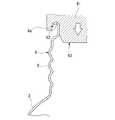
これに対し、カール部形成用治具を、首部に対し回転させずに開口端部に押し当てる場合には、首部のネジ部が座屈変形しやすくなる。
例えば、図5に示すように、略円筒状の筒状体61の下面に断面半円形のカール部形成溝62を形成したカール部形成用治具63を用い、この治具63を、首部4の開口端部4aに対し、回転させずに縦方向(首部軸方向)に押し当てる場合には、首部4に加えられる押付力が周方向に不均一となりやすく、局部的に大きな力が首部4に加えられ、この部分においてネジ部5に座屈変形が生じるおそれがある。
特に、硬度が低いアルミニウム(JIS1070)を用い、ネジ部5形成後にカール部6を形成する場合には、上記治具63を回転させずに首部4に押し付けると、ネジ部5に変形が起こりやすい。
【0025】
【実施例】
(実施例1)
図1および図2に示す液状物充填用容器1を以下のようにして作製した。
図3に示すように、アルミニウム(JIS1070)インゴット材をインパクト成形することにより、外径50mmの有底筒状体21を作製し、この有底筒状体21の内面を洗浄、乾燥した後、この内面にポリアミドイミド樹脂を塗装、焼き付けし、保護塗膜10を形成した。このポリアミドイミド樹脂としては、サンエヌ工業(株)製、ポリアミドイミド系内面ワニスM−2を用いた。
数段階のプレス加工により有底筒状体21の上部を縮径し、肩部3および首部4を形成した後、首部4の内周側および外周側に配置されたネジ押圧部材(図示略)により首部4を押圧成形することによって、首部4にネジ部5(山部の外径:23.1mm)を形成した。
次いで、図4に示すカール部形成用治具23を用い、環状基体24を首部4に対し周方向に回転させ、ローラ25を回転させながら首部4に押し当てることによって開口端部4aを環状凹部28aに沿って湾曲させてカール部6(外径21.4mm)を形成し、図1および図2に示す容器1(胴部2の外径:50mm)を得た。
【0026】
(実施例2)
有底筒状体21の外径を35mmとし、ネジ部5の外径(山部の外径)を23.0mmとし、カール部6の外径を21.5mmとすること以外は実施例1と同様にして容器1(胴部2の外径:35mm)を作製した。
【0027】
上記実施例1および実施例2の容器を、以下に示す電導度試験およびリーク試験に供した。
【0028】
(電導度試験)
5%食塩水を満たした容器1を正極とし、この正極と、容器1内に収容した負極との間に6VのDC電圧をかけ、通電開始から5秒後において両極間に流れる電流値を測定した。
一般に、この電流値が50mA以下であれば、保護塗膜に形成されたピンホールに起因する腐蝕が起こりにくい状態にあり、耐蝕性は良好であるとされる。
【0029】
(リーク試験)
着色した水を容器1内に満たし、首部4にポンプアッセンブリ7を装着した後、容器1を倒立状態として48時間放置した後に、容器口部からの液漏れの有無を目視で確認した。
【0030】
上記実施例1、2の容器1では、電導度試験の結果、両極間に流れた電流は20mA以下であり、十分実用可能なレベルの耐蝕性を有することが確認された。
またリーク試験の結果、液漏れは全く生じなかったことが確認された。
これらの試験結果より、実施例1、2の容器1は、耐蝕性およびシール性の点で優れていることがわかった。
【0031】
【発明の効果】
以上説明したように、本発明の製造方法によって得られた液状物充填用容器にあっては、首部の開口端部が外方に湾曲して形成されたカール部を有するので、カール部の端縁部において保護膜形成が不十分である場合でも、この端縁部が容器内の内容液に接するのを防ぐことができる。従って、内容液によりこの部分が腐食するのを未然に防ぎ、容器の耐蝕性を高めることができる。また内容液が、容器の材料との接触により変質が生じ得るものである場合でも、この内容液の変質を防ぎ、内容液の香りなどが変化するのを防止することができる。また単一の材料から形成されているため、再利用にあたり分解する必要がなく、リサイクルが容易である。また、カール部を、その外径が、ネジ部の外径より小さくなるよう形成することによって、保護キャップなどを首部に装着する際に、これがカール部にぶつかるのを防ぎ、装着の際の操作性を向上させることができる。従って、取扱いが容易となる。
【0032】
また、本発明の液状物充填用容器の製造方法によれば、首部にネジ部を形成した後に、首部の開口端部を外方に湾曲させカール部を形成するので、ネジ部形成に伴うカール部の変形を防ぐことができる。
このため、カール部の変形により容器のシール性が低下するのを防ぐことができる。
また、環状基体とカール部形成ローラとを有し、ローラの外周に環状凹部が形成されたカール部形成用治具を用い、カール部形成ローラを首部の開口端部に押し当て、首部を環状凹部内周面に沿って外方に湾曲させてカール部を形成し、この際、環状基体を首部に対し周方向に回転させるとともに、カール部形成ローラを回転させながら首部に押し当てる方法を採用することによって、首部に加えられる力を周方向に均一化し、局部的に首部に大きな力が加えられるのを防ぐことができる。
このため、比較的硬度が低い材料であるアルミニウム(JIS1070)を用いているにもかかわらず、カール部の変形を防ぎ、平滑な天面を有するカール部を形成し、密封性に優れた液状物充填用容器を製造することができる。またネジ部の座屈変形を起こりにくくすることができる。
【図面の簡単な説明】
【図1】 本発明の液状物充填用容器の一実施形態を示す一部断面図である。
【図2】 図1に示す液状物充填用容器の要部を拡大した断面図である。
【図3】 本発明の液状物充填用容器の製造方法の一実施形態を示す工程図である。
【図4】 本発明の液状物充填用容器の製造方法の他の実施形態を実施するために用いられるカール部形成用治具を示す図であり、(A)は平面図、(B)は側面図である。
【図5】 カール部形成用治具の一例を示す断面図である。
【図6】 従来の液状物充填用容器の一例を示す断面図である。
【図7】 従来の液状物充填用容器の他の例を示す断面図である。
【図8】 従来の液状物充填用容器のさらに他の例を示す断面図である。
【符号の説明】
1・・・液状物充填用容器、2・・・胴部、3・・・肩部、4・・・首部、4a・・・開口端部、5・・・ネジ部、6・・・カール部、10・・・保護塗膜、21・・・筒状体、23・・・カール部形成用治具、28a・・・環状凹部、24・・・環状基体、25・・・カール部形成ローラ[0001]
BACKGROUND OF THE INVENTION
The present invention relatesto a method of manufacturing a container to be filled hair liquid, tonic, hair growth agents, emulsions, liquid substances such as cosmetic water. Specifically, corrosion resistance is good, and relatesto a manufacturing method of easily liquid product fillingcontainer recycling.
[0002]
[Prior art]
As containers for filling liquids such as cosmetics, for example, those shown in FIGS. 6 to 8 are known.
A
Such a container is mainly filled with a hair liquid, a tonic, a hair-restoring agent, and the like, and a
Some are made of glass and have the same shape as the above container, and are mainly used as containers for emulsions, lotions, and the like.
[0003]
[Problems to be solved by the invention]
In liquid filling containers used for cosmetics and the like, it is desirable to give a high-class feeling and metallic feeling depending on the design and material of the outer surface. It is difficult to give a metallic feeling.
In addition, in a glass container, a surface can be given a high-class feeling by making it glass-like, but it is difficult to give a metallic feeling. There is also a problem of being easily damaged by an impact such as dropping.
For this reason, metal containers are used as containers that are easy to give a high-class feeling and metallic feeling and are not easily damaged.
[0004]
7 and 8 show examples of metal containers.
A
[0005]
The container shown in FIG. 8 is described in Japanese Patent Laid-Open No. 9-118345, and the
The
[0006]
However, in the
In addition, the
The present invention has been made in view of the above circumstances, and an object of the present invention is to provide a liquid filling container which is excellent in corrosion resistance and can be easily recycled.
[0007]
[Means for Solving the Problems]
To solve this problem,
In the invention according to
The curl portion (6) is formed using a curl portion forming jig (23),
A plurality of the curl forming jigs (23) are disposed on the rotatable annular base material (24) and the inner peripheral surface of the annular base material (24), and the rotation shaft of the annular base material (24) is provided. A curl forming roller (25) that rotates with a rotation axis orthogonal to the cylindrical base member (26) disposed on the rotation axis of the annular base material (24),
The curl portion forming roller (23) has a base end portion rotatably supported by the annular base material (24) and a tip end portion rotatably supported by the center member (26). And a base portion (27) having a circular cross section and a narrow neck portion (28) extending toward the distal end side of the base portion (27), and an annular concave portion having a circular arc cross section along the circumferential direction on the outer periphery of the neck portion (28). (28a) is formed,
The central member (26) has an outer peripheral diameter smaller than an inner peripheral diameter of the neck (4) of the bottomed tubular body (21),
The open end (4a) of the neck (4) of the bottomed cylindrical body (21) is the curl forming roller (25) of the curl forming jig (23), and the neck (4) is the center. In a state of being separated from the member (26), it is pressed and the neck (4) of the bottomed cylindrical body (21) is bent outward along the inner peripheral surface of the annular recess (28a) to curl ( 6), and at this time, the annular base (24) is rotated in the circumferential direction with respect to the neck (4) of the bottomed tubular body (21), and the curl forming roller (25) is rotated. However, it is a manufacturing method of the container for filling a liquid material, which is pressed against the neck (4) of the bottomed cylindrical body (21).
[0008]
DETAILED DESCRIPTION OF THE INVENTION
Hereinafter, the present invention will be described in detail with reference to the drawings. FIG. 1 and FIG. 2 show an embodimentof a liquid filling containerobtained by the present invention. The
[0009]
The
The outer diameter of the screw portion 5 (the outer diameter of the peak portion) is preferably about 22.5 to 23.5 mm.
A
The curled
In order to provide versatility to existing pump assemblies and caps, it is preferable to set the outer diameters of the
[0010]
On the inner surface of the container 1 (the inner surface of the
The
In particular, it is preferable to use a polyamideimide resin excellent in corrosion resistance and workability.
[0011]
[0012]
Next, taking as an example the case where the
As shown in FIG. 3A, the bottomed
Next, as shown in FIG. 3B, if necessary, the vicinity of the open end of the bottomed
[0013]
Next, after printing the package design or the like on the outer peripheral surface of the bottomed
At this time, in order to adjust the opening end of the
[0014]
Next, as shown in FIG. 3 (D), the
[0015]
Next, as shown in FIGS. 3D and 3E, the
In order to form the curled
The
The
The
A plurality (six in the illustrated example) of the
[0016]
In order to form the curled
The bottomed
As a result, the
At this time, the
In this way, since the opening
The
[0017]
In the
Therefore, it is possible to prevent this portion from being corroded by the content liquid and to improve the corrosion resistance of the
Further, even when the content liquid can be altered by contact with the metal that is the material of the
[0018]
Further, since the
Moreover, since it is made of metal, it is easy to give a high-class feeling and a metallic feeling. In addition, even if an impact is applied, it is difficult to break.
[0019]
Further, by forming the curled
[0020]
Further, by using a polyamideimide resin having excellent processability and durability for the
[0021]
Moreover, according to the manufacturing method of the said embodiment, since the
For this reason, it is possible to prevent the sealing performance of the
On the other hand, when forming the screw portion on the neck portion after forming the curled portion, as the screw portion is formed, the neck portion is pressed and bent and deformed by the screw pressing member. Since a downward tensile force is applied to the neck, it is difficult to form a curled portion having a smooth top surface, and a local recess may be formed in the curled portion. For this reason, a gap may be formed between a cap (such as a pump assembly) attached to the container and the curled portion, and the sealing performance of the container may be deteriorated.
[0022]
Further, according to the above method, the
Therefore, when the
Therefore, the
In addition, since the longitudinal force (axial direction of the neck 4) applied to the
[0023]
On the other hand, when the curl portion forming jig is pressed against the opening end portion without rotating with respect to the neck portion, the screw portion of the neck portion is likely to buckle and deform.
For example, as shown in FIG. 5, a curl
In particular, when aluminum having a low hardness (JIS 1070) is used and the curled
[0025]
【Example】
Example 1
The
As shown in FIG. 3, by impact-molding an aluminum (JIS1070) ingot material, a bottomed
After the diameter of the upper portion of the bottomed
Next, by using the
[0026]
(Example 2)
Example 1 except that the outer diameter of the bottomed
[0027]
The containers of Example 1 and Example 2 were subjected to the following conductivity test and leak test.
[0028]
(Conductivity test)
A
In general, if this current value is 50 mA or less, corrosion due to pinholes formed in the protective coating is unlikely to occur, and the corrosion resistance is considered good.
[0029]
(Leak test)
After filling the
[0030]
In the
As a result of the leak test, it was confirmed that no liquid leak occurred.
From these test results, it was found that the
[0031]
【The invention's effect】
As described above,in the liquid filling containerobtained by themanufacturing method of the present invention, the opening end portion of the neck portion has the curled portion formed by bending outward, so that the end of the curled portion Even when the protective film is insufficiently formed at the edge, the edge can be prevented from coming into contact with the content liquid in the container. Therefore, it is possible to prevent this portion from being corroded by the content liquid and improve the corrosion resistance of the container. Further, even when the content liquid can be altered by contact with the material of the container, the content liquid can be prevented from being altered and the scent of the content liquid can be prevented from changing. Moreover, since it is formed from a single material, it does not need to be disassembled for reuse and is easy to recycle. In addition, by forming the curled part so that its outer diameter is smaller than the outer diameter of the screw part, it prevents it from hitting the curled part when wearing a protective cap, etc. Can be improved. Therefore, handling becomes easy.
[0032]
Further, according to the method for manufacturing a container for filling a liquid material of the present invention, the curled portion is formed by forming the curled portion by bending the opening end of the neck portion outward after forming the threaded portion at the neck portion. The deformation of the part can be prevented.
For this reason, it can prevent that the sealing performance of a container falls by deformation | transformation of a curl part.
Also, using a curl forming jig that has an annular base and a curl forming roller, and in which an annular recess is formed on the outer periphery of the roller, the curl forming roller is pressed against the opening end of the neck, and the neck is annular A curled part is formed by curving outward along the inner peripheral surface of the recess. At this time, the annular base is rotated in the circumferential direction with respect to the neck, and the method of pressing the curled part forming roller against the neck is adopted. By doing so, the force applied to the neck can be made uniform in the circumferential direction, and a large force can be prevented from being applied locally to the neck.
For this reason, despite using aluminum (JIS 1070), which is a relatively low hardness material, the curled portion is prevented from being deformed, a curled portion having a smooth top surface is formed, and a liquid material having excellent sealing properties A filling container can be manufactured. In addition, buckling deformation of the thread portion can be made difficult to occur.
[Brief description of the drawings]
FIG. 1 is a partial sectional view showing an embodiment of a liquid filling container according to the present invention.
FIG. 2 is an enlarged cross-sectional view of a main part of the liquid filling container shown in FIG.
FIG. 3 is a process diagram showing an embodiment of a method for producing a liquid filling container of the present invention.
FIG. 4 is a view showing a curl forming jig used for carrying out another embodiment of the method for manufacturing a liquid filling container of the present invention, (A) is a plan view, and (B) is a plan view. It is a side view.
FIG. 5 is a cross-sectional view showing an example of a curl forming jig.
FIG. 6 is a cross-sectional view showing an example of a conventional liquid filling container.
FIG. 7 is a cross-sectional view showing another example of a conventional liquid filling container.
FIG. 8 is a cross-sectional view showing still another example of a conventional liquid filling container.
[Explanation of symbols]
DESCRIPTION OF
Claims (1)
Translated fromJapanese前記カール部(6)の形成がカール部形成用治具(23)を用いて行われ、 The curl portion (6) is formed using a curl portion forming jig (23),
このカール部形成用治具(23)は、回転可能な環状基材(24)と、この環状基材(24)の内周面に複数個配設され、環状基材(24)の回転軸に対して直交する回転軸を有して回転するカール部形成ローラ(25)と、前記環状基材(24)の回転軸上に配された円柱状の中心部材(26)を有し、 A plurality of the curl forming jigs (23) are disposed on the rotatable annular base material (24) and the inner peripheral surface of the annular base material (24), and the rotation shaft of the annular base material (24) is provided. A curl forming roller (25) that rotates with a rotation axis orthogonal to the cylindrical base member (26) disposed on the rotation axis of the annular base material (24),
前記カール部形成ローラ(23)は、その基端部が前記環状基材(24)に回転可能に軸支され、その先端部が前記中心部材(26)に回転可能に軸支されているとともに、断面円形の基部(27)と、この基部(27)の先端側に延びる細径とされた首部28を有し、この首部(28)の外周には周方向に沿う断面円弧状の環状凹部(28a)が形成され、 The curl portion forming roller (23) has a base end portion rotatably supported by the annular base material (24) and a tip end portion rotatably supported by the center member (26). And a base portion (27) having a circular cross section and a narrow neck portion (28) extending toward the distal end side of the base portion (27), and an annular concave portion having a circular arc cross section along the circumferential direction on the outer periphery of the neck portion (28). (28a) is formed,
前記中心部材(26)は、その外周径が前記有底筒状体(21)の首部(4)の内周径よりも小さくされたものであり、 The central member (26) has an outer peripheral diameter smaller than an inner peripheral diameter of the neck (4) of the bottomed tubular body (21),
前記有底筒状体(21)の首部(4)の開口端部(4a)を前記カール部形成用治具(23)のカール部形成ローラ(25)に、その首部(4)が前記中心部材(26)から離間した状態で、押し当て、前記有底筒状体(21)の首部(4)を前記環状凹部(28a)の内周面に沿って外方に湾曲させてカール部(6)を形成し、この際、前記環状基体(24)を前記有底筒状体(21)の首部(4)に対し周方向に回転させるとともに、前記カール部形成ローラ(25)を回転させながら前記有底筒状体(21)の首部(4)に押し当てることを特徴とする液状物充填用容器の製造方法。 The open end (4a) of the neck (4) of the bottomed cylindrical body (21) is the curl forming roller (25) of the curl forming jig (23), and the neck (4) is the center. In a state of being separated from the member (26), it is pressed and the neck (4) of the bottomed cylindrical body (21) is bent outward along the inner peripheral surface of the annular recess (28a) to curl ( 6), and at this time, the annular base (24) is rotated in the circumferential direction with respect to the neck (4) of the bottomed tubular body (21), and the curl forming roller (25) is rotated. However, it presses against the neck part (4) of the said bottomed cylindrical body (21), The manufacturing method of the container for liquid substance fillings characterized by the above-mentioned.
Priority Applications (1)
| Application Number | Priority Date | Filing Date | Title |
|---|---|---|---|
| JP2001016029AJP4647799B2 (en) | 2000-02-21 | 2001-01-24 | Method for manufacturing liquid filling container |
Applications Claiming Priority (3)
| Application Number | Priority Date | Filing Date | Title |
|---|---|---|---|
| JP2000-43318 | 2000-02-21 | ||
| JP2000043318 | 2000-02-21 | ||
| JP2001016029AJP4647799B2 (en) | 2000-02-21 | 2001-01-24 | Method for manufacturing liquid filling container |
Publications (2)
| Publication Number | Publication Date |
|---|---|
| JP2001315745A JP2001315745A (en) | 2001-11-13 |
| JP4647799B2true JP4647799B2 (en) | 2011-03-09 |
Family
ID=26585769
Family Applications (1)
| Application Number | Title | Priority Date | Filing Date |
|---|---|---|---|
| JP2001016029AExpired - LifetimeJP4647799B2 (en) | 2000-02-21 | 2001-01-24 | Method for manufacturing liquid filling container |
Country Status (1)
| Country | Link |
|---|---|
| JP (1) | JP4647799B2 (en) |
Families Citing this family (13)
| Publication number | Priority date | Publication date | Assignee | Title |
|---|---|---|---|---|
| CN1309619C (en) | 2001-12-28 | 2007-04-11 | 三菱麻铁里亚尔株式会社 | Bottles, bottles and thread forming devices |
| KR100706264B1 (en)* | 2004-07-27 | 2007-04-12 | 손태현 | 3-piece steel cans and manufacturing method thereof |
| JP4800023B2 (en)* | 2005-12-02 | 2011-10-26 | 大和製罐株式会社 | Aluminum alloy can with small capacity screw |
| KR100851220B1 (en) | 2007-10-22 | 2008-08-07 | 동부제철 주식회사 | Three-piece steel can manufacturing method and necking device used therein |
| US20110113732A1 (en)* | 2009-11-13 | 2011-05-19 | The Coca-Cola Company | Method of isolating column loading and mitigating deformation of shaped metal vessels |
| US9663846B2 (en) | 2011-09-16 | 2017-05-30 | Ball Corporation | Impact extruded containers from recycled aluminum scrap |
| CA2990040C (en) | 2013-04-09 | 2021-07-20 | Ball Corporation | Aluminum impact extruded bottle with threaded neck made from recycled aluminum and enhanced alloys |
| US20180044155A1 (en) | 2016-08-12 | 2018-02-15 | Ball Corporation | Apparatus and Methods of Capping Metallic Bottles |
| AU2016433840B2 (en) | 2016-12-30 | 2020-10-15 | Ball Corporation | Aluminum alloy for impact extruded containers and method of making the same |
| EP3583043A4 (en) | 2017-02-16 | 2021-04-14 | Ball Corporation | Apparatus and methods of forming and applying roll-on pilfer proof closures on the threaded neck of metal containers |
| JP2019010670A (en)* | 2017-06-30 | 2019-01-24 | ユニバーサル製缶株式会社 | Can molding method and can molding device |
| MX2020002563A (en) | 2017-09-15 | 2020-07-13 | Ball Corp | System and method of forming a metallic closure for a threaded container. |
| US12291371B2 (en) | 2022-02-04 | 2025-05-06 | Ball Corporation | Method for forming a curl and a threaded metallic container including the same |
Family Cites Families (3)
| Publication number | Priority date | Publication date | Assignee | Title |
|---|---|---|---|---|
| JPH0332432A (en)* | 1989-06-28 | 1991-02-13 | Toyo Seikan Kaisha Ltd | Method and tool for forming flange part of can body |
| JPH09118345A (en)* | 1995-10-20 | 1997-05-06 | Machiyama Seisakusho:Kk | Container for filling liquid substance and manufacture thereof |
| JP2000191006A (en)* | 1998-12-28 | 2000-07-11 | Takeuchi Press Ind Co Ltd | Screwed can, manufacture thereof and capped container employing screwed can |
- 2001
- 2001-01-24JPJP2001016029Apatent/JP4647799B2/ennot_activeExpired - Lifetime
Also Published As
| Publication number | Publication date |
|---|---|
| JP2001315745A (en) | 2001-11-13 |
Similar Documents
| Publication | Publication Date | Title |
|---|---|---|
| JP4647799B2 (en) | Method for manufacturing liquid filling container | |
| CA1327167C (en) | Metal container and method of manufacturing the same | |
| JP7027229B2 (en) | Bottle-shaped cans with caps and their manufacturing equipment | |
| IE66835B1 (en) | Method of making a dispensing head and the corresponding head and dispenser | |
| JPS6021539B2 (en) | Composite tube and its manufacturing method | |
| JP4434562B2 (en) | Metal container with inner surface coated and method for manufacturing the same | |
| JP2007331813A (en) | Metal container with metal cap screwed tightly thereto and method of molding metal container | |
| US20230219127A1 (en) | Method of manufacturing can body and manufacturing line of the same | |
| CN220174663U (en) | Foldable inner plug and applicator comprising same | |
| US4284211A (en) | Nibbed ferrule for holding cap | |
| JPH09118345A (en) | Container for filling liquid substance and manufacture thereof | |
| JP2004141943A (en) | Metal bottle can and method for manufacturing the same | |
| EP4201546A1 (en) | Preform can and method for producing same | |
| JP2003011979A (en) | Metallic container | |
| JP5254701B2 (en) | Metal can container | |
| JPH0776381A (en) | Production of aerosol device | |
| JPS6340468Y2 (en) | ||
| JP4422315B2 (en) | Double aerosol container | |
| JPH0634298Y2 (en) | Thin coating / thick coating switching coating container | |
| JP3457381B2 (en) | Mascara applicator | |
| JPH0661510B2 (en) | Aerosol device | |
| JP2006159068A (en) | Method of coating inside surface of can main body and can main body | |
| JP2022000386A (en) | Metallic container lid | |
| JP7438651B2 (en) | Tube container and method for manufacturing tube container | |
| JP2003251425A (en) | Reseal can manufacturing method |
Legal Events
| Date | Code | Title | Description |
|---|---|---|---|
| A621 | Written request for application examination | Free format text:JAPANESE INTERMEDIATE CODE: A621 Effective date:20071026 | |
| A977 | Report on retrieval | Free format text:JAPANESE INTERMEDIATE CODE: A971007 Effective date:20100712 | |
| A131 | Notification of reasons for refusal | Free format text:JAPANESE INTERMEDIATE CODE: A131 Effective date:20100720 | |
| A521 | Request for written amendment filed | Free format text:JAPANESE INTERMEDIATE CODE: A523 Effective date:20100915 | |
| TRDD | Decision of grant or rejection written | ||
| A01 | Written decision to grant a patent or to grant a registration (utility model) | Free format text:JAPANESE INTERMEDIATE CODE: A01 Effective date:20101124 | |
| A01 | Written decision to grant a patent or to grant a registration (utility model) | Free format text:JAPANESE INTERMEDIATE CODE: A01 | |
| A61 | First payment of annual fees (during grant procedure) | Free format text:JAPANESE INTERMEDIATE CODE: A61 Effective date:20101209 | |
| FPAY | Renewal fee payment (event date is renewal date of database) | Free format text:PAYMENT UNTIL: 20131217 Year of fee payment:3 | |
| R150 | Certificate of patent or registration of utility model | Ref document number:4647799 Country of ref document:JP Free format text:JAPANESE INTERMEDIATE CODE: R150 Free format text:JAPANESE INTERMEDIATE CODE: R150 | |
| R250 | Receipt of annual fees | Free format text:JAPANESE INTERMEDIATE CODE: R250 | |
| R250 | Receipt of annual fees | Free format text:JAPANESE INTERMEDIATE CODE: R250 | |
| R250 | Receipt of annual fees | Free format text:JAPANESE INTERMEDIATE CODE: R250 | |
| R250 | Receipt of annual fees | Free format text:JAPANESE INTERMEDIATE CODE: R250 | |
| R250 | Receipt of annual fees | Free format text:JAPANESE INTERMEDIATE CODE: R250 | |
| R250 | Receipt of annual fees | Free format text:JAPANESE INTERMEDIATE CODE: R250 | |
| R250 | Receipt of annual fees | Free format text:JAPANESE INTERMEDIATE CODE: R250 | |
| R250 | Receipt of annual fees | Free format text:JAPANESE INTERMEDIATE CODE: R250 | |
| EXPY | Cancellation because of completion of term |