JP4647527B2 - Vibration model device for articulated vehicle of magnetic levitation railway - Google Patents
Vibration model device for articulated vehicle of magnetic levitation railwayDownload PDFInfo
- Publication number
- JP4647527B2 JP4647527B2JP2006079536AJP2006079536AJP4647527B2JP 4647527 B2JP4647527 B2JP 4647527B2JP 2006079536 AJP2006079536 AJP 2006079536AJP 2006079536 AJP2006079536 AJP 2006079536AJP 4647527 B2JP4647527 B2JP 4647527B2
- Authority
- JP
- Japan
- Prior art keywords
- vehicle
- railway
- vibration model
- articulated
- axis
- Prior art date
- Legal status (The legal status is an assumption and is not a legal conclusion. Google has not performed a legal analysis and makes no representation as to the accuracy of the status listed.)
- Expired - Fee Related
Links
Images

Classifications
- G—PHYSICS
- G01—MEASURING; TESTING
- G01M—TESTING STATIC OR DYNAMIC BALANCE OF MACHINES OR STRUCTURES; TESTING OF STRUCTURES OR APPARATUS, NOT OTHERWISE PROVIDED FOR
- G01M17/00—Testing of vehicles
- G01M17/007—Wheeled or endless-tracked vehicles
Landscapes
- Physics & Mathematics (AREA)
- General Physics & Mathematics (AREA)
- Control Of Vehicles With Linear Motors And Vehicles That Are Magnetically Levitated (AREA)
Description
Translated fromJapanese本発明は、超電導磁気浮上式鉄道車両の走行中の台車運動および車体運動を模擬する連接車両用振動模型装置に関するものである。 The present invention relates to a vibration model device for an articulated vehicle that simulates a bogie motion and a vehicle body motion during travel of a superconducting magnetic levitation railway vehicle.
超電導磁気浮上式鉄道車両は、車上の超電導磁石と地上の地上コイルが高速で相対運動することにより発生する非接触の磁気ばねにより支持されている(下記特許文献1、2参照)。
上記したように、超電導磁気浮上式鉄道車両の1次支持系(台車〜ガイドウェイ間)は、磁気浮上している走行時は、非接触の磁気ばねで構成されており、この磁気ばねは、車上側の超電導磁石と地上側の地上コイルが高速で相対運動することにより発生するため、定置の試験装置での再現は困難である。 As described above, the primary support system (between the carriage and the guideway) of the superconducting magnetically levitated railway vehicle is composed of a non-contact magnetic spring during magnetic levitation, and this magnetic spring is Since it is generated by the relative motion of the superconducting magnet on the upper side of the vehicle and the ground coil on the ground side, it is difficult to reproduce with a stationary test apparatus.
また、この磁気ばねは、前後xと上下zとy軸周りのピッチ、左右yとx軸回りのロールとz軸回りのヨーが連成する特性を有しており、例えば、左右y方向に変位した場合は、左右y方向の力が発生する以外に、x軸回りのロールおよびz軸回りのヨーの回転モーメントも発生する。さらに、磁気ばねは、車両重量や超電導磁石の励磁電流や超電導コイル〜地上コイル間空隙等のパラメータが変動することにより、そのばね定数が変化する特性を有している。磁気ばねはこのような特性を有しているため、各種の走行状態を模擬する必要がある試験装置では、コイルばねや空気ばねのような機械ばねを用いてこの磁気ばね特性を再現することは困難である。 In addition, this magnetic spring has a characteristic in which a pitch around front and rear x, up and down z and y axis, a roll around left and right y and x axis, and a yaw around z axis are coupled. In the case of displacement, in addition to the force in the right and left y direction, a rotational moment of the roll about the x axis and the yaw about the z axis is also generated. Furthermore, the magnetic spring has a characteristic that its spring constant changes when parameters such as the vehicle weight, the exciting current of the superconducting magnet, and the gap between the superconducting coil and the ground coil fluctuate. Since the magnetic spring has such characteristics, it is not possible to reproduce this magnetic spring characteristic by using a mechanical spring such as a coil spring or an air spring in a test apparatus that needs to simulate various traveling conditions. Have difficulty.
そのため、連接構造を有する超電導磁気浮上式鉄道車両の走行中の台車運動および車体運動を模擬する有効な振動模型装置はこれまで存在していないのが現状であった。すなわち、本発明は、上記状況に鑑みて、超電導磁気浮上式鉄道の連接車両の台車運動および車体運動を再現可能な連接車両用振動模型装置を提供することを目的とする。 For this reason, there has been no effective vibration model device that simulates the bogie movement and the vehicle body movement of a superconducting magnetically levitated railway vehicle having an articulated structure. That is, in view of the above situation, an object of the present invention is to provide an articulated vehicle vibration model device capable of reproducing the bogie motion and the vehicle body motion of an articulated vehicle of a superconducting magnetically levitated railway.
本発明は、上記目的を達成するために、
〔1〕磁気浮上式鉄道の連接車両用振動模型装置において、連接構造を有する磁気浮上式鉄道の車体間に配置される台車の運動を再現するとともに、非接触の磁気ばねの連成を模擬するパラレルメカニズムによる6自由度閉ループ機構を配置することを特徴とする。In order to achieve the above object, the present invention provides
[1] In a vibration model device for an articulated vehicle of a magnetically levitated railway, the movement of a carriage disposed between the bodies of the magnetically levitated railway having an articulated structure is reproduced, and the coupling of non-contact magnetic springs is simulated. A six-degree-of-freedom closed loop mechanism using a parallel mechanism is arranged.
〔2〕上記〔1〕記載の連接構造を有する磁気浮上式鉄道の連接車両用振動模型装置において、前記パラレルメカニズムによる6自由度閉ループ機構には、走行速度・台車間隔に応じた位相差を有する外乱を入力することを特徴とする。 [2] In the vibration model apparatus for an articulated vehicle of a magnetically levitated railway having the articulated structure described in [1] above, the six-degree-of-freedom closed-loop mechanism based on the parallel mechanism has a phase difference corresponding to a traveling speed and a carriage interval. It is characterized by inputting a disturbance.
〔3〕上記〔1〕記載の連接構造を有する磁気浮上式鉄道の連接車両用振動模型装置において、前記磁気ばねのパラメータの変更を容易にしたことを特徴とする。 [3] In the vibration model device for an articulated vehicle of a magnetically levitated railway having the articulated structure described in [1] above, the parameter of the magnetic spring is easily changed.
〔4〕上記〔1〕記載の連接構造を有する磁気浮上式鉄道の連接車両用振動模型装置において、前記台車の運動に伴い、前記台車よりばね・ダンパ機構によって支持された車体の前後x軸方向、左右y軸方向、上下z軸方向、前後x軸回りのロール、左右y軸回りのピッチ、上下z軸回りのヨーが連成する振動を模擬することを特徴とする。 [4] In the vibration model device for a connected vehicle of a magnetically levitated railway having the connection structure according to [1] above, a longitudinal x-axis direction of a vehicle body supported by a spring / damper mechanism from the carriage as the carriage moves Simulating vibration in which rolls around the left and right y-axis direction, up and down z-axis direction, front and rear x-axis, pitch around the left and right y-axis, and yaw around the up and down z-axis are coupled.
本発明によれば、連接構造を有する超電導磁気浮上式鉄道車両の台車運動および車体運動を再現可能である。それにより、例えば、車体曲げ振動現象の解明や、振動制御適用による乗り心地向上効果の検討に資することができる。 According to the present invention, it is possible to reproduce the bogie motion and the vehicle body motion of a superconducting magnetically levitated railway vehicle having an articulated structure. Thereby, for example, it is possible to contribute to the elucidation of the bending vibration phenomenon of the vehicle body and the examination of the riding comfort improvement effect by applying the vibration control.
本発明の磁気浮上式鉄道の連接車両用振動模型装置は、磁気浮上式鉄道車両の車体間に配置される台車の運動を再現する、非接触の磁気ばねを模擬するパラレルメカニズムによる6自由度閉ループ機構を配置する。また、車体は現車同様に台車よりばね・ダンパ機構を用いて支持される。 The vibration model apparatus for a levitation railway articulated vehicle according to the present invention is a six-degree-of-freedom closed loop using a parallel mechanism that simulates a non-contact magnetic spring that reproduces the movement of a carriage disposed between the bodies of a magnetic levitation railway vehicle. Arrange the mechanism. In addition, the vehicle body is supported from the carriage by a spring / damper mechanism as in the current vehicle.
以下、本発明の実施形態について図面を参照しながら詳細に説明する。 Hereinafter, embodiments of the present invention will be described in detail with reference to the drawings.
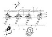
図1は本発明の実施例を示す磁気浮上式鉄道の連接車両用振動模型装置の模式図、図2は磁気浮上式鉄道の連接車両用振動模型装置のパラレルメカニズムによる6自由度閉ループ機構とその制御装置を示す図である。 FIG. 1 is a schematic diagram of a vibration model device for an articulated vehicle of a magnetic levitation railway showing an embodiment of the present invention, and FIG. 2 is a six-degree-of-freedom closed loop mechanism using a parallel mechanism of the vibration model device for an articulated vehicle of a magnetic levitation railway. It is a figure which shows a control apparatus.
これらの図において、1は複数車体が連接している磁気浮上式鉄道車両、2はその連接している車体1の間に配置される台車、3は磁気浮上式鉄道車両1と台車2との間に配置される車体支持ばね、4はその台車2に加わる磁気ばねに相当し、台車運動を模擬するパラレルメカニズムによる6自由度閉ループ機構であり、ガイドウェイ5と台車2間に配置される。また、パラレルメカニズムによる6自由度閉ループ機構4にはアクチュエータ13が配置されており、そのアクチュエータ13にはアクチュエータ駆動用油圧源6と油圧系統7が接続されるとともに、アクチュエータ13を制御する制御装置8と制御系統9が接続されている。 In these drawings, 1 is a magnetically levitated railway vehicle in which a plurality of vehicle bodies are connected, 2 is a carriage disposed between the connected
そして、図2に示すように、このパラレルメカニズムによる6自由度閉ループ機構4は、超電導磁気浮上式鉄道車両の台車の運動を模擬するため、6自由度(前後x、左右y、上下z、x軸回りのロール、y軸回りのピッチ、z軸回りのヨー)の動きができる。つまり、台車2の運動を模擬するパラレルメカニズムによる6自由度閉ループ機構4は、ベース11と台車2との間に6個のリンク12を備えており、それらのリンク12にはそれぞれアクチュエータ13が配置されており、それらのアクチュエータ13は伸縮アーム14を有している。また、油圧サーボバルブ15が配置されており、これには油圧系統7が接続されいる。さらに、油圧サーボバルブ15には制御プログラム22を有する制御装置8が接続されており、制御プログラム22に従って、油圧サーボバルブ15が制御されることにより、パラレルメカニズムによる6自由度閉ループ機構4は、超電導磁気浮上式鉄道車両の台車の運動を模擬した、6自由度(前後x、左右y、上下z、x軸回りのロール、y軸回りのピッチ、z軸回りのヨー)の動きができる。 As shown in FIG. 2, the 6-degree-of-freedom closed-loop mechanism 4 based on this parallel mechanism simulates the motion of the bogie of the superconducting magnetically levitated railway vehicle, and therefore has 6 degrees of freedom (front-rear x, left-right y, up-down z, x A roll around the axis, a pitch around the y axis, and a yaw around the z axis are possible. That is, the six-degree-of-freedom closed loop mechanism 4 using a parallel mechanism that simulates the movement of the
なお、制御装置8内には制御プログラム22以外に、CPU22、車体間隔、車体重量、走行速度、磁気パラメータなどが記憶された記憶装置23、出力インターフェース24、入力装置25、表示装置26などが備えられている。 In addition to the
このように、制御装置8の制御プログラム22に従ってパラレルメカニズムによる6自由度閉ループ機構4は駆動され、台車2に走行速度・台車間隔などに応じた位相差を有する外乱情報10を入力し、走行中の台車運動を再現する。車体〜台車間の2次支持系は、現在の車両と同様に、空気ばね・油圧ダンパ等から構成され、車体運動を再現する。 Thus, according to the
このように、本発明によれば、パラレルメカニズムによる6自由度閉ループ機構4により台車運動を再現できる。その場合に、磁気ばね等のパラメータの変更は入力装置25から容易に行うことができる。つまり、走行速度の変化や車体重量増加等による磁気ばね定数の変化を模擬することができる。 Thus, according to the present invention, the cart motion can be reproduced by the 6-DOF closed-loop mechanism 4 based on the parallel mechanism. In that case, the parameter such as the magnetic spring can be easily changed from the
また、本発明によれば、車体曲げ振動を模擬することができ、振動制御適用による車体振動低減策の検討を行うためのツールとして利用できる。 Further, according to the present invention, it is possible to simulate vehicle body bending vibration and use it as a tool for studying vehicle body vibration reduction measures by applying vibration control.
なお、本発明は上記実施例に限定されるものではなく、本発明の趣旨に基づいて種々の変形が可能であり、これらを本発明の範囲から排除するものではない。 In addition, this invention is not limited to the said Example, A various deformation | transformation is possible based on the meaning of this invention, and these are not excluded from the scope of the present invention.
本発明の磁気浮上式鉄道の連接車両用振動模型装置は、高周波領域における乗り心地評価を行う連接車両用振動模型装置に利用可能である。 The vibration model device for a connected vehicle of a magnetically levitated railway according to the present invention can be used as a vibration model device for a connected vehicle that performs ride comfort evaluation in a high frequency region.
1 複数車体が連接している磁気浮上式鉄道車両
2 磁気浮上式鉄道車両の車体間に配置される台車
3 車体支持ばね
4 パラレルメカニズムによる6自由度閉ループ機構
5 ガイドウェイ
6 アクチュエータ駆動用油圧源
7 油圧系統
8 制御装置
9 制御系統
10 外乱情報
11 ベース
12 6個のリンク
13 アクチュエータ
14 伸縮アーム
15 油圧サーボバルブ
21 制御部
22 制御プログラム
23 記憶装置
24 出力インターフェース
25 入力装置
26 表示装置DESCRIPTION OF SYMBOLS 1 Magnetically levitated railway vehicle with which several vehicle bodies are connected 2 Carriage arrange | positioned between the bodies of a magnetically levitated
Claims (4)
Translated fromJapanesePriority Applications (1)
| Application Number | Priority Date | Filing Date | Title |
|---|---|---|---|
| JP2006079536AJP4647527B2 (en) | 2006-03-22 | 2006-03-22 | Vibration model device for articulated vehicle of magnetic levitation railway |
Applications Claiming Priority (1)
| Application Number | Priority Date | Filing Date | Title |
|---|---|---|---|
| JP2006079536AJP4647527B2 (en) | 2006-03-22 | 2006-03-22 | Vibration model device for articulated vehicle of magnetic levitation railway |
Publications (2)
| Publication Number | Publication Date |
|---|---|
| JP2007256019A JP2007256019A (en) | 2007-10-04 |
| JP4647527B2true JP4647527B2 (en) | 2011-03-09 |
Family
ID=38630421
Family Applications (1)
| Application Number | Title | Priority Date | Filing Date |
|---|---|---|---|
| JP2006079536AExpired - Fee RelatedJP4647527B2 (en) | 2006-03-22 | 2006-03-22 | Vibration model device for articulated vehicle of magnetic levitation railway |
Country Status (1)
| Country | Link |
|---|---|
| JP (1) | JP4647527B2 (en) |
Cited By (1)
| Publication number | Priority date | Publication date | Assignee | Title |
|---|---|---|---|---|
| JP2012233839A (en)* | 2011-05-09 | 2012-11-29 | Railway Technical Research Institute | Simulative vibration experiment device for a magnetic levitation railway vehicle using air spring |
Families Citing this family (8)
| Publication number | Priority date | Publication date | Assignee | Title |
|---|---|---|---|---|
| JP5425749B2 (en)* | 2010-11-17 | 2014-02-26 | 公益財団法人鉄道総合技術研究所 | Reproduction method of bogie motion using suspension interaction force in model test equipment of floating vehicle |
| WO2013085472A2 (en)* | 2011-08-16 | 2013-06-13 | Yavuz Abdulkadir | Multi degrees of freedom, multi platformed shaking simulator |
| US9470590B2 (en)* | 2015-02-12 | 2016-10-18 | Nhk Spring Co., Ltd. | Coil spring modeling apparatus |
| US9811067B2 (en)* | 2015-02-12 | 2017-11-07 | Nhk Spring Co., Ltd. | Coil spring modeling apparatus and method of the same |
| US9835217B2 (en)* | 2015-02-12 | 2017-12-05 | Nhk Spring Co., Ltd. | Coil spring modeling apparatus and method utilizing a torsion detection to control an actuator unit |
| KR102252316B1 (en)* | 2019-10-10 | 2021-05-14 | 한국철도기술연구원 | Driving stability experimental apparatus for capsule train |
| CN114279659B (en)* | 2020-09-27 | 2023-06-23 | 中车株洲电力机车研究所有限公司 | Hinge system test method, system, medium and equipment |
| CN112284765A (en)* | 2020-11-07 | 2021-01-29 | 倪中雷 | Positioning detection debugging device for automobile seat |
Family Cites Families (8)
| Publication number | Priority date | Publication date | Assignee | Title |
|---|---|---|---|---|
| JP3202765B2 (en)* | 1991-07-08 | 2001-08-27 | 財団法人鉄道総合技術研究所 | Power supply method for superconducting maglev railway |
| JPH05281281A (en)* | 1992-03-31 | 1993-10-29 | Railway Technical Res Inst | Device for detecting abnormality of ground coil of superconductive magnetic levitation type railroad |
| JP3084904B2 (en)* | 1992-04-06 | 2000-09-04 | 株式会社日立製作所 | Railway vehicle test apparatus and method |
| JP3073433B2 (en)* | 1995-08-07 | 2000-08-07 | 三菱重工業株式会社 | 6-axis load device |
| JP3087242B2 (en)* | 1997-03-31 | 2000-09-11 | 川崎重工業株式会社 | Test method and test apparatus for mobile parts |
| DE19903132B4 (en)* | 1999-01-27 | 2008-12-04 | Daimler Ag | Nick and Ausdrehvorrichtung for a rail vehicle |
| AU6891200A (en)* | 1999-08-25 | 2001-03-19 | Ap Automotive Systems, Inc. | Dual mast system for simulation testing |
| JP2002014012A (en)* | 2000-06-30 | 2002-01-18 | Central Japan Railway Co | Left and right stationary acceleration simulator for railway |
- 2006
- 2006-03-22JPJP2006079536Apatent/JP4647527B2/ennot_activeExpired - Fee Related
Cited By (1)
| Publication number | Priority date | Publication date | Assignee | Title |
|---|---|---|---|---|
| JP2012233839A (en)* | 2011-05-09 | 2012-11-29 | Railway Technical Research Institute | Simulative vibration experiment device for a magnetic levitation railway vehicle using air spring |
Also Published As
| Publication number | Publication date |
|---|---|
| JP2007256019A (en) | 2007-10-04 |
Similar Documents
| Publication | Publication Date | Title |
|---|---|---|
| JP4647527B2 (en) | Vibration model device for articulated vehicle of magnetic levitation railway | |
| JP3915122B2 (en) | Driving simulator | |
| US9682642B2 (en) | Seat suspension | |
| Goodall et al. | Active controls in ground transportation—A review of the state-of-the-art and future potential | |
| KR102275786B1 (en) | Bearing testing machine | |
| JP6212054B2 (en) | Land vehicle driving simulation equipment | |
| JP5061339B2 (en) | Articulated vehicle testing equipment | |
| KR101075136B1 (en) | 6-Axis Road Simulator Test System | |
| CN114812986B (en) | Vibration test system for superconducting maglev train suspension frame | |
| JP2006138827A (en) | Tire HIL simulator | |
| CN104122096A (en) | Vehicle test apparatus and vehicle test system | |
| JP5650050B2 (en) | Vibration simulation test equipment for magnetically levitated railway vehicles using air springs | |
| JP2009271025A (en) | Chassis dynamometer | |
| JP2014215242A (en) | Test device for vehicle | |
| Yu et al. | Series active variable geometry suspension: Full-car prototyping and road testing | |
| CN203824726U (en) | Testing stand for vibration reduction of vehicle active suspension system based on magneto-rheological damper | |
| Yu et al. | Parallel active link suspension: Full car application with frequency-dependent multiobjective control strategies | |
| CN105818723B (en) | For the multiple freedom parallel mechanism vibration reduction platform of automobile seat | |
| Yue et al. | Simulation and experimental study on the active stability of high-speed trains | |
| Han | A study on the dynamic modeling of a magnetic levitation vehicle | |
| KR101154514B1 (en) | 6-axis road simulator test apparatus | |
| CN113640021B (en) | Rolling test bed for developing active guiding controller of double-shaft independent wheel bogie | |
| Stribersky et al. | The development of an integrated suspension control technology for passenger trains | |
| JP6474112B2 (en) | Vehicle vibration control device | |
| JP2014077709A (en) | Stationary test device capable of reproducing motion of magnetic levitation railway vehicle when abnormality occurs during travel on wheels |
Legal Events
| Date | Code | Title | Description |
|---|---|---|---|
| A621 | Written request for application examination | Free format text:JAPANESE INTERMEDIATE CODE: A621 Effective date:20080711 | |
| A977 | Report on retrieval | Free format text:JAPANESE INTERMEDIATE CODE: A971007 Effective date:20101110 | |
| TRDD | Decision of grant or rejection written | ||
| A01 | Written decision to grant a patent or to grant a registration (utility model) | Free format text:JAPANESE INTERMEDIATE CODE: A01 Effective date:20101207 | |
| A01 | Written decision to grant a patent or to grant a registration (utility model) | Free format text:JAPANESE INTERMEDIATE CODE: A01 | |
| A61 | First payment of annual fees (during grant procedure) | Free format text:JAPANESE INTERMEDIATE CODE: A61 Effective date:20101208 | |
| FPAY | Renewal fee payment (event date is renewal date of database) | Free format text:PAYMENT UNTIL: 20131217 Year of fee payment:3 | |
| R150 | Certificate of patent or registration of utility model | Free format text:JAPANESE INTERMEDIATE CODE: R150 | |
| FPAY | Renewal fee payment (event date is renewal date of database) | Free format text:PAYMENT UNTIL: 20131217 Year of fee payment:3 | |
| S533 | Written request for registration of change of name | Free format text:JAPANESE INTERMEDIATE CODE: R313533 | |
| FPAY | Renewal fee payment (event date is renewal date of database) | Free format text:PAYMENT UNTIL: 20131217 Year of fee payment:3 | |
| R350 | Written notification of registration of transfer | Free format text:JAPANESE INTERMEDIATE CODE: R350 | |
| LAPS | Cancellation because of no payment of annual fees |