JP4645910B2 - Editing apparatus, editing method, and program - Google Patents
Editing apparatus, editing method, and programDownload PDFInfo
- Publication number
- JP4645910B2 JP4645910B2JP2006117972AJP2006117972AJP4645910B2JP 4645910 B2JP4645910 B2JP 4645910B2JP 2006117972 AJP2006117972 AJP 2006117972AJP 2006117972 AJP2006117972 AJP 2006117972AJP 4645910 B2JP4645910 B2JP 4645910B2
- Authority
- JP
- Japan
- Prior art keywords
- data
- clip
- editing
- unit
- edited
- Prior art date
- Legal status (The legal status is an assumption and is not a legal conclusion. Google has not performed a legal analysis and makes no representation as to the accuracy of the status listed.)
- Expired - Fee Related
Links
Images


Classifications
- G—PHYSICS
- G11—INFORMATION STORAGE
- G11B—INFORMATION STORAGE BASED ON RELATIVE MOVEMENT BETWEEN RECORD CARRIER AND TRANSDUCER
- G11B27/00—Editing; Indexing; Addressing; Timing or synchronising; Monitoring; Measuring tape travel
- G11B27/02—Editing, e.g. varying the order of information signals recorded on, or reproduced from, record carriers
- G11B27/031—Electronic editing of digitised analogue information signals, e.g. audio or video signals
- G11B27/036—Insert-editing
- G—PHYSICS
- G11—INFORMATION STORAGE
- G11B—INFORMATION STORAGE BASED ON RELATIVE MOVEMENT BETWEEN RECORD CARRIER AND TRANSDUCER
- G11B27/00—Editing; Indexing; Addressing; Timing or synchronising; Monitoring; Measuring tape travel
- G11B27/02—Editing, e.g. varying the order of information signals recorded on, or reproduced from, record carriers
- G11B27/031—Electronic editing of digitised analogue information signals, e.g. audio or video signals
- G11B27/034—Electronic editing of digitised analogue information signals, e.g. audio or video signals on discs
- G—PHYSICS
- G11—INFORMATION STORAGE
- G11B—INFORMATION STORAGE BASED ON RELATIVE MOVEMENT BETWEEN RECORD CARRIER AND TRANSDUCER
- G11B20/00—Signal processing not specific to the method of recording or reproducing; Circuits therefor
- G11B20/10—Digital recording or reproducing
- G—PHYSICS
- G11—INFORMATION STORAGE
- G11B—INFORMATION STORAGE BASED ON RELATIVE MOVEMENT BETWEEN RECORD CARRIER AND TRANSDUCER
- G11B27/00—Editing; Indexing; Addressing; Timing or synchronising; Monitoring; Measuring tape travel
- G11B27/02—Editing, e.g. varying the order of information signals recorded on, or reproduced from, record carriers
- G11B27/031—Electronic editing of digitised analogue information signals, e.g. audio or video signals
- G—PHYSICS
- G11—INFORMATION STORAGE
- G11B—INFORMATION STORAGE BASED ON RELATIVE MOVEMENT BETWEEN RECORD CARRIER AND TRANSDUCER
- G11B27/00—Editing; Indexing; Addressing; Timing or synchronising; Monitoring; Measuring tape travel
- G11B27/10—Indexing; Addressing; Timing or synchronising; Measuring tape travel
- G11B27/102—Programmed access in sequence to addressed parts of tracks of operating record carriers
- G11B27/105—Programmed access in sequence to addressed parts of tracks of operating record carriers of operating discs
Landscapes
- Engineering & Computer Science (AREA)
- Multimedia (AREA)
- Signal Processing (AREA)
- Management Or Editing Of Information On Record Carriers (AREA)
- Television Signal Processing For Recording (AREA)
- Signal Processing For Digital Recording And Reproducing (AREA)
Description
Translated fromJapanese本発明は、編集装置および編集方法、並びにプログラムに関し、特に、挿入区間に複数のファイルの一部または全部が含まれる場合、その挿入区間に含まれる先頭のファイルが新たなデータにより上書きされ、先頭のファイル以外のファイルはそのまま保護されたように、編集結果を再生することができるようにした編集装置および編集方法、並びにプログラムに関する。The present invention relates to anediting device, anediting method, and a program, and in particular, when a part or all of a plurality of files are included in an insertion section, the top file included in the insertion section is overwritten with new data, and the top The present invention relates to anediting apparatus, anediting method, and a program that can reproduce an editing result so that files other than the above file are protected as they are.
従来、VTR(Video Tape Recorder)において、アセンブル編集、インサート編集などのリニア編集が行われている。 Conventionally, linear editing such as assembly editing and insert editing has been performed in a VTR (Video Tape Recorder).
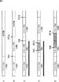
ここで、図1A乃至図1Eを参照して、リニア編集について説明する。 Here, linear editing will be described with reference to FIGS. 1A to 1E.
なお、図1A乃至図1Eでは、撮影の結果得られたクリップがテープに記録されるものとする。ここで、クリップとは、例えば、1回の撮影処理(撮影開始から撮影終了までの撮影処理)により得られた画像データ、その画像データに対応する音声データ等の集合体を指す。また、クリップ#iとは、i回目の撮影処理により得られたクリップを表している。 1A to 1E, a clip obtained as a result of shooting is recorded on a tape. Here, the clip refers to, for example, a collection of image data obtained by one shooting process (shooting process from the start of shooting to the end of shooting), audio data corresponding to the image data, and the like. Clip #i represents a clip obtained by the i-th shooting process.
図1Aに示すように、再生時間が10秒であるクリップ#1が記録されている場合に、ユーザが、再生時間が10秒であるクリップ#2をアセンブル編集するとき、ユーザは、例えば、編集区間のイン点として、クリップ#1の終端の、編集結果に対するタイムコード(以下、編集結果タイムコードという)を表す終端位置を指定し、アウト点として、イン点からクリップ#2の再生時間である10秒後の編集結果タイムコードを指定する。この場合、図1Bに示すように、クリップ#1の終端に続いて、シーケンシャルに、クリップ#2が先頭から終端まで記録される。 As shown in FIG. 1A, when
また、ユーザは、アセンブル編集を行うとき、イン点として、記録済みのクリップのうちの先頭の編集結果タイムコードを表す先頭位置が最後のクリップの途中の編集結果タイムコードを指定することもできる。 In addition, when the assemble editing is performed, the user can also specify an editing result time code in the middle of the last clip whose leading position represents the leading editing result time code of the recorded clips as the in point.
例えば、図1Bに示したように、クリップ#1とクリップ#2が記録されている場合に、ユーザが、再生時間が12秒であるクリップ#3をアセンブル編集するとき、編集区間のイン点として、クリップ#2の開始位置から8秒後の編集結果タイムコードを指定し、アウト点として、イン点からクリップ#3の再生時間である12秒後の編集結果タイムコードを指定すると、図1Cに示すように、クリップ#2の開始位置の8秒後から、終端位置までの区間が、クリップ#3により上書きされる。 For example, as shown in FIG. 1B, when
即ち、クリップ#2の再生時間は8秒となる。従って、テープの連続再生が行われると、テープ上の記録順、即ちクリップ#1、クリップ#2、クリップ#3の順にクリップが再生され、クリップ#1の再生が開始してから、18秒後にクリップ#3が再生される。 That is, the playback time of
一方、図1Cに示したようにクリップ#1乃至クリップ#3が記録されている場合に、ユーザがインサート編集を行うとき、ユーザは、新たなデータをインサート(挿入)させる挿入区間を編集区間として、その編集区間の開始位置の編集結果タイムコードをイン点として指定し、終了位置の編集結果タイムコードをアウト点として指定する。この場合、編集区間が、挿入対象のクリップにより上書きされる。 On the other hand, when
例えば、編集区間が、クリップ#2の開始位置から終端位置までの間の区間である場合、図1Dに示すように、編集区間が上書きされる。また、編集区間のイン点が、クリップ#2の開始位置から終端位置までの間の区間にあり、アウト点が、クリップ#3の開始位置から終端位置までの区間にある場合、即ち編集区間が2個のクリップにまたがっている場合も、図1Eに示すように、編集区間が上書きされる。即ち、クリップ#2のイン点から終端までの区間と、クリップ#3の先頭からアウト点までの区間とが上書きされる。 For example, when the editing section is a section from the start position to the end position of
以上のように、インサート編集が行われる場合、編集区間が上書きされるので、編集前後で、各クリップの開始位置と終了位置の編集結果タイムコードは変化しない。例えば、図1Dや図1Eに示すように、インサート編集が行われた場合であっても、クリップ#1の再生が開始してから、18秒後にクリップ#3が再生される。 As described above, when insert editing is performed, since the editing section is overwritten, the editing result time code of the start position and end position of each clip does not change before and after editing. For example, as shown in FIGS. 1D and 1E, even when insert editing is performed,
また、近年、ディスクなどの記録媒体にファイルとして記録されたクリップに対して、ノンリニア編集を行う装置も普及している。このようなノンリニア編集を行う装置は、編集結果を構成するデータの再生順序を表す編集リストを生成し、その編集リストを参照して編集結果を再生する。 In recent years, an apparatus for performing nonlinear editing on a clip recorded as a file on a recording medium such as a disk has become widespread. An apparatus that performs such nonlinear editing generates an edit list that represents the playback order of data that constitutes an edit result, and plays back the edit result with reference to the edit list.
図2は、編集リストの一例を示している。 FIG. 2 shows an example of the edit list.
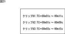
図2の編集リストには、再生順に上からクリップを特定する情報(図2の例では、「クリップ#i」)が記述され、その情報に対応して、編集結果に含まれる各クリップの区間の開始位置と終了位置を表す、各クリップに対するタイムコード(以下、クリップタイムコードという)が記述されている。 In the edit list in FIG. 2, information for specifying a clip from the top in the playback order (in the example of FIG. 2, “clip #i”) is described, and the section of each clip included in the edit result corresponding to that information A time code for each clip (hereinafter referred to as a clip time code) representing the start position and the end position of is described.
図2の編集リストによれば、クリップ#1のクリップタイムコードが1秒から11秒までの区間、クリップ#2のクリップタイムコードが1秒から9秒までの区間、クリップ#3のクリップタイムコードが3秒から15秒までの区間が順に、編集結果として再生される。 According to the edit list of FIG. 2, the clip time code of
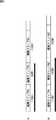
即ち、図3に示すように、編集結果に含まれるクリップ#1のデータである編集クリップ#1は、再生時間が14秒であるクリップ#1のうちの、クリップタイムコードが1秒から11秒までの区間であり、再生時間は10秒である。また、編集結果に含まれるクリップ#2のデータである編集クリップ#2は、再生時間が12秒であるクリップ#2のうちの、クリップタイムコードが1秒から9秒までの区間であり、再生時間は8秒である。さらに、編集結果に含まれるクリップ#3のデータである編集クリップ#3は、再生時間が16秒であるクリップ#3のうちの、クリップタイムコードが3秒から15秒までの区間であり、再生時間は12秒である。 That is, as shown in FIG. 3, the edited
そして、図2の編集リストを参照して、図4Aに示すように、編集クリップ#1、編集クリップ#2、編集クリップ#3の順に、クリップが編集結果として再生される。即ち、編集クリップ#1の再生が開始してから18秒後に、編集クリップ#3の再生が開始される。 Then, referring to the edit list in FIG. 2, as shown in FIG. 4A, clips are reproduced as edit results in the order of edit
ここで、ユーザは、編集結果において、編集クリップ#2を2秒間延長する場合、図2の編集リストのクリップ#2に対応するクリップタイムコードを変更する。例えば、ユーザは、クリップ#2に対応する終了位置を表すクリップタイムコードを9秒から11秒に変更する。その結果、編集クリップ#2は、クリップ#2のうちの、クリップタイムコードが1秒から11秒までの区間となり、再生時間は10秒となる。 Here, when the
従って、図4Bに示すように、再生時間が10秒である編集クリップ#1、再生時間が10秒である編集クリップ#2、再生時間が12秒である編集クリップ#3の順に、クリップが編集結果として再生される。即ち、編集クリップ#1の再生が開始してから20秒後に、編集クリップ#3の再生が開始される。 Therefore, as shown in FIG. 4B, the clips are edited in the order of
以上のように、ノンリニア編集は、編集リストの記述内容を追加、変更、または削除することにより行われる。また、ユーザが編集結果として用いる編集クリップを延長する場合、その編集クリップ以降に再生される編集クリップにおいて、再生開始時刻は遅れるが、再生時間は変化しない。 As described above, nonlinear editing is performed by adding, changing, or deleting the description content of the edit list. Further, when the user extends an editing clip used as an editing result, the playback start time is delayed in the editing clip played after the editing clip, but the playback time does not change.
上述したように、リニア編集とノンリニア編集は、それぞれ異なる特徴を有しており、ユーザの編集方法もそれぞれ異なっている。従って、どちらか一方に慣れているユーザであっても、他方を行うことは困難である。 As described above, linear editing and non-linear editing have different characteristics, and user editing methods are also different. Therefore, even a user accustomed to either one is difficult to do the other.
そこで、リニア編集とノンリニア編集の機能を混在させたハイブリッドの編集装置が考えられている。このようなハイブリッドの編集装置は、ノンリニア編集時と同様に、編集結果を構成するデータの再生順序を表すインデックスファイルを生成し、そのインデックスファイルを参照して編集結果を再生する。 Therefore, a hybrid editing apparatus in which linear editing and nonlinear editing functions are mixed is considered. Similar to the nonlinear editing, such a hybrid editing apparatus generates an index file representing the reproduction order of data constituting the editing result, and reproduces the editing result with reference to the index file.
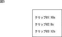
図5は、インデックスファイルの一例を示している。 FIG. 5 shows an example of the index file.
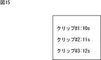
図5のインデックスファイルには、再生順に上からクリップを特定する情報(図5の例では、「クリップ#i」)が記述され、その情報に対応して、各クリップの再生時間が記述されている。図5のインデックスファイルによれば、図6に示すように再生時間が10秒であるクリップ#1、再生時間が8秒であるクリップ#2、再生時間が12秒であるクリップ#3が、図7Aに示すように順に編集結果として再生される。従って、クリップ#1の再生が開始してから18秒後に、クリップ#3の再生が開始される。 In the index file of FIG. 5, information for specifying a clip from the top in the playback order (“clip #i” in the example of FIG. 5) is described, and the playback time of each clip is described corresponding to the information. Yes. According to the index file of FIG. 5, as shown in FIG. 6,
ここで、ユーザは、1つのクリップの先頭位置から終端位置までの区間内に新たなクリップを挿入する場合、VTRと同様に、編集区間として、挿入区間のイン点とアウト点を指定することにより、インサート編集を行うことが可能である。例えば、ユーザが、クリップ#2の先頭位置から終端位置までの所定の位置をイン点とアウト点として指定し、インサート編集を行うと、図7Bに示すように、クリップ#2のイン点からアウト点までの区間のデータが、新たなクリップにより上書きされる。なお、ハイブリッドの編集装置では、VTRと同様に、アセンブリ編集を行うことも可能である。 Here, when inserting a new clip in the section from the beginning position to the end position of one clip, the user designates the in and out points of the insertion section as the editing section, similarly to the VTR. It is possible to perform insert editing. For example, when the user designates a predetermined position from the beginning position to the end position of
一方、編集を迅速に行うために、データをセクタの整数倍のデータ量である年輪サイズ単位で光ディスクに記録する記録装置がある(例えば、特許文献1参照)。 On the other hand, there is a recording apparatus that records data on an optical disk in units of annual ring size, which is a data amount that is an integral multiple of a sector, for quick editing (see, for example, Patent Document 1).
上述したように、ユーザがインサート編集を行う場合、編集区間のすべてのデータが、インサート対象とするクリップにより上書きされる。また、ユーザが、編集リストを用いてノンリニア編集を行う場合、編集結果内に新たな編集クリップを追加することは容易だが、新たな編集クリップにより上書きされたように再生するためには、編集リストを複雑に変更する必要があり、困難である。 As described above, when the user performs insert editing, all data in the editing section is overwritten by the clip to be inserted. In addition, when a user performs non-linear editing using an edit list, it is easy to add a new edit clip to the edit result, but in order to play back as if overwritten by a new edit clip, the edit list It is necessary and complicated to change.
従って、編集区間として指定された挿入区間に複数のクリップの一部または全部が含まれる場合、その挿入区間に含まれる先頭のクリップが挿入対象のクリップにより上書きされ、先頭のクリップ以外のファイルはそのまま保護されたように、編集結果を再生したいというユーザの要望に応えることは困難であった。 Therefore, when some or all of the clips are included in the insertion section specified as the editing section, the first clip included in the insertion section is overwritten by the clip to be inserted, and the files other than the first clip are left as they are. As protected, it was difficult to meet the user's desire to replay the edited results.
本発明は、このような状況に鑑みてなされたものであり、挿入区間に複数のファイルの一部または全部が含まれる場合、その挿入区間に含まれる先頭のファイルが新たなデータにより上書きされ、先頭のファイル以外のファイルはそのまま保護されたように、編集結果を再生することができるようにするものである。 The present invention has been made in view of such a situation, and when the insertion section includes some or all of a plurality of files, the top file included in the insertion section is overwritten with new data, The editing result can be reproduced as if the files other than the first file are protected as they are.
本発明の一側面の編集装置は、編集対象のクリップ単位のデータの所定の区間に新たなデータを挿入し、前記新たなデータの後に前記所定の区間の挿入前のデータを含む前記編集対象のクリップのうちの先頭のクリップ以外のクリップのデータを接続する編集であるこじあけ編集を行う編集装置において、前記所定の区間を挿入区間として指定する指定手段と、前記新たなデータのうち、前記先頭のクリップに挿入されるデータである第1のデータを、前記編集対象のクリップ単位のデータを記録する記録媒体の前記挿入区間の開始位置から前記先頭のクリップの終端までのデータが記録される領域に上書きし、前記新たなデータのうちの前記第1のデータ以外のデータである第2のデータを、前記記録媒体の未記録領域に記録するように制御する記録制御手段と、こじあけ編集後のデータの再生順序を表す順序情報を生成する生成手段とを備え、前記生成手段は、前記挿入区間の開始位置までの前記編集対象のクリップ単位のデータ、前記新たなデータ、前記先頭のクリップの終端より後ろの前記編集対象のクリップ単位のデータの順に再生するように、前記順序情報を生成し、前記記録制御手段は、前記新たなデータを、前記先頭のクリップのこじあけ編集後のクリップとして記録させる。The editing apparatus according to one aspect of the present invention inserts new data into a predetermined section of data inclip units to beedited, and includes the data to be edited including data before insertion of the predetermined section after the new data. inthe beginning of the connectingclip data exceptthe clip pry-open an editing editing apparatus for editingof the clip, and designation means for designating a predetermined interval as the insertion section, of the newdata, the head ofthe the first data is the data that is inserted into theclip, in the area where the data to the end of thebeginning oftheclip from the start position of the insertion section of the recording medium for recording data of the editedclip unit is recorded Overwriting and controlling the second data other than the first data in the new data to be recorded in an unrecorded area of the recording medium. And recording control means for, and generating means for generating an order information indicating a reproduction order of the edited data pry-open, said generating means, the dataof the edited clip units to the starting position of the insertion section, wherein newdata, so as to reproduce the order of dataof the edited clip units behind the end of thebeginning oftheclip, to generate the order information, the recording control means, the new data, thehead oftheClips are recorded as aclip after editing .
前記編集装置は、編集モードを、前記こじあけ編集を行うこじあけモード、または、前記編集対象のクリップ単位のデータの前記挿入区間に前記新たなデータを上書きする編集である上書き編集を行う上書き編集モードに設定する設定手段をさらに設け、前記記録制御手段は、前記編集モードが前記こじあけモードである場合、前記新たなデータのうち、前記第1のデータを前記記録媒体の前記挿入区間の開始位置から前記先頭のクリップの終端までのデータが記録される領域に上書きし、前記第2のデータを前記記録媒体の未記録領域に記録するように制御し、前記編集モードが前記上書きモードである場合、前記新たなデータを前記記録媒体の前記挿入区間のデータが記録される領域に上書きするように制御し、前記生成手段は、前記編集モードが前記こじあけモードである場合、前記挿入区間の開始位置までの前記編集対象のクリップ単位のデータ、前記新たなデータ、前記先頭のクリップの終端より後ろの前記編集対象のクリップ単位のデータの順に再生するように、前記順序情報を生成し、前記編集モードが前記上書きモードである場合、前記挿入区間の開始位置までの前記編集対象のクリップ単位のデータ、前記新たなデータ、前記挿入区間の終了位置からの前記編集対象のクリップ単位のデータの順に再生するように、前記順序情報を生成し、前記記録制御手段は、前記編集モードがこじあけモードである場合、前記新たなデータを、前記先頭のクリップのこじあけ編集後のクリップとして記録させることができる。The editing apparatus changes the editing mode to a pruning mode for performing the pruning editing or an overwriting editing mode for performing overwriting editing, which is an editing for overwriting the new data in the insertion section of the data of theclip unit to be edited. Setting means for setting is further provided, and when the editing mode is the pruning mode, the recording control means sets the first data out of the new data from the start position of the insertion section of the recording medium.When the data up to the end of the firstclip is overwritten in the recorded area and the second data is recorded in the unrecorded area of the recording medium, and the editing mode is the overwrite mode, Control is performed so that new data is overwritten in an area in which data in the insertion section of the recording medium is recorded, and the generation means If mode is the pry-open mode, the dataof the edited clip units to the starting position of the insertion section, the newdata, in the order of the dataof the edited clip units behind the end of thebeginning oftheclip If the order information is generated and the editing mode is the overwrite mode,the clip unit data to beedited up to the start position of the insertion section, the new data, the end of the insertion section to play in the order of the dataof the edited clip unit from the position to generate the order information, the recording control unit, when the editing mode is the pry-open mode, the new data, thehead oftheClips can be recorded asclips after prying and editing .
本発明の一側面の編集方法は、編集対象のクリップ単位のデータの所定の区間に新たなデータを挿入し、前記新たなデータの後に前記所定の区間の挿入前のデータを含む前記編集対象のクリップのうちの先頭のクリップ以外のクリップのデータを接続する編集であるこじあけ編集を行う編集装置の編集方法において、前記所定の区間を挿入区間として指定し、前記新たなデータのうち、前記先頭のクリップに挿入されるデータである第1のデータを、前記先頭のクリップのこじあけ編集後のクリップとして、前記編集対象のクリップ単位のデータを記録する記録媒体の前記挿入区間の開始位置から前記先頭のクリップの終端までのデータが記録される領域に上書きし、前記新たなデータのうちの前記第1のデータ以外のデータである第2のデータを、前記先頭のクリップのこじあけ編集後のクリップとして前記記録媒体の未記録領域に記録するように制御し、前記挿入区間の開始位置までの前記編集対象のクリップ単位のデータ、前記新たなデータ、前記先頭のクリップの終端より後ろの前記編集対象のクリップ単位のデータの順に再生するように、こじあけ編集後のデータの再生順序を表す順序情報を生成するステップを含む。In the editing method according to one aspect of the present invention, new data is inserted into a predetermined section ofclip unitdata to be edited, and the editing target includes data before insertion of the predetermined section after the new data. in the editing process ofthe head of the connectingclip data exceptthe clip pry-open an editing editing apparatus for editingof the clip, to specify the predetermined interval as the insertion section, of the newdata, the head ofthe the first data is the data that is inserted into theclip, as aclip after editing pry-open of thebeginning oftheclip, from a starting position of the insertion section of the recording medium for recording data of the editedclip unit of thehead overwriting in the region where the data to the end of theclip is recorded, a second de is data other than the first data of the new data The motor, controlled so as to record the unrecorded area of the recording medium as aclip after editing pry-open of thebeginning oftheclip, the dataof the edited clip units to the starting position of the insertion section, the new dataAnd a step of generating order information indicating the reproduction order of the data after the line editing so as to reproducethe data inunits of the clip to be edited afterthe end of theheadclip .
本発明の一側面のプログラムは、編集対象のクリップ単位のデータの所定の区間に新たなデータを挿入し、前記新たなデータの後に前記所定の区間の挿入前のデータを含む前記編集対象のクリップのうちの先頭のクリップ以外のクリップのデータを接続する編集であるこじあけ編集を行う処理を、コンピュータに行わせるプログラムにおいて、前記所定の区間を挿入区間として指定し、前記新たなデータのうち、前記先頭のクリップに挿入されるデータである第1のデータを、前記先頭のクリップのこじあけ編集後のクリップとして、前記編集対象のクリップ単位のデータを記録する記録媒体の前記挿入区間の開始位置から前記先頭のクリップの終端までのデータが記録される領域に上書きし、前記新たなデータのうちの前記第1のデータ以外のデータである第2のデータを、前記先頭のクリップのこじあけ編集後のクリップとして前記記録媒体の未記録領域に記録するように制御し、前記挿入区間の開始位置までの前記編集対象のクリップ単位のデータ、前記新たなデータ、前記先頭のクリップの終端より後ろの前記編集対象のクリップ単位のデータの順に再生するように、こじあけ編集後のデータの再生順序を表す順序情報を生成するステップを含む。The program according to one aspect of the present invention inserts new data into a predetermined section of data inclip units to beedited, and includes the data to be edited including data before the insertion of the predetermined section after the new data.In the program for causing the computer to perform a process for performing the editing for connecting the data of theclip other than the firstclip of the above, the predetermined section is designated as the insertion section, and the new data amongthe new datathe head of the first data is data that is inserted into theclip, as aclip after editing pry-open of thebeginning oftheclip, said from the start position of the insertion section of the recording medium for recording data of the editedclip units overwriting in the regionwhere the beginning of theclip data to the end is recorded, said first data or more of said new data Second data, thebeginning ofthe control is recorded asclip after editing pry-open the clip in an unrecorded area of the recording medium,the edited clip units to the starting position of the insertion section is a data includingdata, the newdata, as reproduced in the order of the dataof the edited clip units behind the end of thebeginning oftheclip, the step of generating the order information indicating a reproduction order of the data after editing pry-open .
本発明の一側面においては、編集対象のクリップ単位のデータの所定の区間に新たなデータを挿入し、新たなデータの後に所定の区間の挿入前のデータを含む編集対象のクリップのうちの先頭のクリップ以外のクリップのデータを接続する編集であるこじあけ編集を行う場合に、所定の区間が挿入区間として指定され、新たなデータのうち、先頭のクリップに挿入されるデータである第1のデータが、先頭のクリップのこじあけ編集後のクリップとして、編集対象のクリップ単位のデータを記録する記録媒体の挿入区間の開始位置から先頭のクリップの終端までのデータが記録される領域に上書きされ、新たなデータのうちの第1のデータ以外のデータである第2のデータが、先頭のクリップのこじあけ編集後のクリップとして記録媒体の未記録領域に記録されるように制御され、挿入区間の開始位置までの編集対象のクリップ単位のデータ、新たなデータ、先頭のクリップの終端より後ろの編集対象のクリップ単位のデータの順に再生されるように、こじあけ編集後のデータの再生順序を表す順序情報が生成される。In one aspect of the present invention, new data is inserted into a predetermined section ofclip unitdata to be edited, and the beginning of the editing target clip including data before insertion of the predetermined section after the new data when theclip than theclip data editing a is pry-open edit to connect, predetermined section is designated as an insertion section, of the newdata, the first data is data to be inserted atthe beginning of theclip but asthe beginning of theclip after editing pry-open the clip, it is overwritten in the area where the data to the end ofthe beginning of aclip from the start position of the insertion section of the recording medium for recording data of aclip unit to be edited is recorded, a new second data which is the first data other than the data of such data, onlythe beginning of theclip of pry-open recording medium as aclip after editing Is controlled so as to be recorded in the recording area, datato be edited clip units to the start position of the insert section, are reproduced in the order of the dataof the newdata, the beginning of theclip of the clip unit of the edited behind the termination As described above, the order information indicating the reproduction order of the data after the editing is generated.
以上のように、本発明の一側面によれば、挿入区間に複数のファイルの一部または全部が含まれる場合、その挿入区間に含まれる先頭のファイルが新たなデータにより上書きされ、先頭のファイル以外のファイルはそのまま保護されたように、編集結果を再生することができる。 As described above, according to one aspect of the present invention, when a part or all of a plurality of files are included in an insertion section, the top file included in the insertion section is overwritten with new data, and the top file The editing result can be reproduced as if the other files are protected as they are.
以下に本発明の実施の形態を説明するが、本発明の構成要件と、明細書又は図面に記載の実施の形態との対応関係を例示すると、次のようになる。この記載は、本発明をサポートする実施の形態が、明細書又は図面に記載されていることを確認するためのものである。従って、明細書又は図面中には記載されているが、本発明の構成要件に対応する実施の形態として、ここには記載されていない実施の形態があったとしても、そのことは、その実施の形態が、その構成要件に対応するものではないことを意味するものではない。逆に、実施の形態が構成要件に対応するものとしてここに記載されていたとしても、そのことは、その実施の形態が、その構成要件以外の構成要件には対応しないものであることを意味するものでもない。 Embodiments of the present invention will be described below. Correspondences between the constituent elements of the present invention and the embodiments described in the specification or the drawings are exemplified as follows. This description is intended to confirm that the embodiments supporting the present invention are described in the specification or the drawings. Therefore, even if there is an embodiment which is described in the specification or the drawings but is not described here as an embodiment corresponding to the constituent elements of the present invention, that is not the case. It does not mean that the form does not correspond to the constituent requirements. Conversely, even if an embodiment is described here as corresponding to a configuration requirement, that means that the embodiment does not correspond to a configuration requirement other than the configuration requirement. It's not something to do.
本発明の一側面の編集装置は、
編集対象のクリップ単位のデータの所定の区間に新たなデータを挿入し、前記新たなデータの後に前記所定の区間の挿入前のデータを含む前記編集対象のクリップのうちの先頭のクリップ以外のクリップのデータを接続する編集であるこじあけ編集を行う編集装置(例えば、図8のディスク編集装置10)において、
前記所定の区間を挿入区間として指定する指定手段(例えば、図10の指定部63)と、
前記新たなデータのうち、前記先頭のクリップに挿入されるデータである第1のデータを、前記編集対象のクリップ単位のデータを記録する記録媒体(例えば、図8の光ディスク11)の前記挿入区間の開始位置から前記先頭のクリップの終端までのデータが記録される領域に上書きし、前記新たなデータのうちの前記第1のデータ以外のデータである第2のデータを、前記記録媒体の未記録領域に記録するように制御する記録制御手段(例えば、図10の記録制御部62)と、
こじあけ編集後のデータの再生順序を表す順序情報を生成する生成手段(例えば、図10のインデックス更新部64)と
を備え、
前記生成手段は、前記挿入区間の開始位置までの前記編集対象のクリップ単位のデータ、前記新たなデータ、前記先頭のクリップの終端より後ろの前記編集対象のクリップ単位のデータの順に再生するように、前記順序情報を生成し、
前記記録制御手段は、前記新たなデータを、前記先頭のクリップのこじあけ編集後のクリップとして記録させる。An editing device according to one aspect of the present invention includes:
Clips other than the firstclipamong the clips to be edited that include new data inserted in a predetermined section of theclip unitdata to be edited and include data before the insertion of the predetermined section after the new data In an editing device (for example, the
Designating means (for example, designating
Ofthe new data, the first data which is data inserted into theheadclip is used as the insertion section of the recording medium (for example, the
Generation means (for example, the
The generation unit reproducesthe data inunits of the clip to beedited up to the start position of the insertion section, the new data, andthe data inunits of the clip to be edited after the end of theheadclip. , Generate the order information,
The recording control means records the new data asa clip after opening and editing theheadclip .
本発明の一側面の編集装置は、
編集モードを、前記こじあけ編集を行うこじあけモード、または、前記編集対象のクリップ単位のデータの前記挿入区間に前記新たなデータを上書きする編集である上書き編集を行う上書き編集モードに設定する設定手段(例えば、図10のモード設定部61)
をさらに備え、
前記記録制御手段は、前記編集モードが前記こじあけモードである場合、前記新たなデータのうち、前記第1のデータを前記記録媒体の前記挿入区間の開始位置から前記先頭のクリップの終端までのデータが記録される領域に上書きし、前記第2のデータを前記記録媒体の未記録領域に記録するように制御し、前記編集モードが前記上書きモードである場合、前記新たなデータを前記記録媒体の前記挿入区間のデータが記録される領域に上書きするように制御し、
前記生成手段は、前記編集モードが前記こじあけモードである場合、前記挿入区間の開始位置までの前記編集対象のクリップ単位のデータ、前記新たなデータ、前記先頭のクリップの終端より後ろの前記編集対象のクリップ単位のデータの順に再生するように、前記順序情報を生成し、前記編集モードが前記上書きモードである場合、前記挿入区間の開始位置までの前記編集対象のクリップ単位のデータ、前記新たなデータ、前記挿入区間の終了位置からの前記編集対象のクリップ単位のデータの順に再生するように、前記順序情報を生成し、
前記記録制御手段は、前記編集モードがこじあけモードである場合、前記新たなデータを、前記先頭のクリップのこじあけ編集後のクリップとして記録させる。An editing device according to one aspect of the present invention includes:
Setting means for setting the edit mode to the pruning mode for performing the pruning editing or the overwriting editing mode for performing the overwriting editing which is the editing for overwriting the new data in the insertion section of the data of theclip unit to be edited ( (For example, the
Further comprising
The recording control means may control, when the editing mode is the pry-open mode, among the new data, the data of the first data from the start position of the insertion section of the recording medium to the end of thebeginning oftheclip Is overwritten in the area to be recorded, and the second data is recorded in an unrecorded area of the recording medium. When the editing mode is the overwrite mode, the new data is stored in the recording medium. Control to overwrite the area where the data of the insertion section is recorded,
When the editing mode is the pruning mode, the generating means is the editingunit clip data up to the start position of the insertion section, the new data, theediting target after the end of thetopclip If the editing mode is the overwrite mode,the clip unit data to beedited up to the start position of the insertion section, the new data is generated. The order information is generated so that data is reproduced in the order ofthe clip unit data to beedited from the end position of the insertion section,
When the editing mode is the pruning mode, the recording control means records the new data asa clip after the pruning editing of thetopclip .
本発明の一側面の編集方法は、
編集対象のクリップ単位のデータの所定の区間に新たなデータを挿入し、前記新たなデータの後に前記所定の区間の挿入前のデータを含む前記編集対象のクリップのうちの先頭のクリップ以外のクリップのデータを接続する編集であるこじあけ編集を行う編集装置(例えば、図8のディスク編集装置10)の編集方法において、
前記所定の区間を挿入区間として指定し(例えば、図16のステップS1)、
前記新たなデータのうち、前記先頭のクリップに挿入されるデータである第1のデータを、前記先頭のクリップのこじあけ編集後のクリップとして、前記編集対象のクリップ単位のデータを記録する記録媒体(例えば、図8の光ディスク11)の前記挿入区間の開始位置から前記先頭のクリップの終端までのデータが記録される領域に上書きし、前記新たなデータのうちの前記第1のデータ以外のデータである第2のデータを、前記先頭のクリップのこじあけ編集後のクリップとして前記記録媒体の未記録領域に記録するように制御し(例えば、図16のステップS7およびS10)、
前記挿入区間の開始位置までの前記編集対象のクリップ単位のデータ、前記新たなデータ、前記先頭のクリップの終端より後ろの前記編集対象のクリップ単位のデータの順に再生するように、こじあけ編集後のデータの再生順序を表す順序情報を生成する(例えば、図16のステップS13)
ステップを含む。An editing method according to one aspect of the present invention includes:
Clips other than the firstclipamong the clips to be edited that include new data inserted in a predetermined section of theclip unitdata to be edited and include data before the insertion of the predetermined section after the new data In an editing method of an editing apparatus (for example, the
The predetermined section is designated as an insertion section (for example, step S1 in FIG. 16),
Amongthe new data, the first data, which is data inserted into theheadclip , is used asthe clip after theheadclip editing, and the recording medium for recording the data of theclip unit to be edited ( for example, in the overwritten from a start position of the insert section in the area in which data is recorded to the end of thebeginning oftheclip, the data other than the first data of the new data of the optical disk 11) in FIG. 8 some second data, the control to record the unrecorded area of the recording medium as aclip after editing pry-open of thebeginning oftheclip (e.g., step S7 and S10 in FIG. 16),
The dataafter clip editing is reproduced so thatthe data ofthe clip unit to beedited up to the start position of the insertion section, the new data, andthe data ofthe clip unit of the edit target after the end of theheadclip are played in this order. Order information representing the data reproduction order is generated (for example, step S13 in FIG. 16).
Includes steps.
以下、本発明を適用した具体的な実施の形態について、図面を参照しながら詳細に説明する。 Hereinafter, specific embodiments to which the present invention is applied will be described in detail with reference to the drawings.
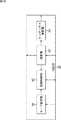
図8は、本発明を適用したディスク編集装置の一実施の形態の構成例を示している。なお、図8のディスク編集装置10は、リニア編集とノンリニア編集の機能を混在させたハイブリッドの編集装置である。 FIG. 8 shows a configuration example of an embodiment of a disc editing apparatus to which the present invention is applied. 8 is a hybrid editing apparatus in which linear editing and non-linear editing functions are mixed.
スピンドルモータ12は、サーボ制御部15からのスピンドルモータ駆動信号に基づいて、光ディスク11をCLV(Constant Linear Velocity)またはCAV(Constant Angular Velocity)で回転駆動する。 The
ピックアップ部13は、信号処理部16から供給される記録信号に基づきレーザ光の出力を制御して、光ディスク11に記録信号を記録する。ピックアップ部13はまた、光ディスク11にレーザ光を集光して照射するとともに、光ディスク11からの反射光を光電変換して電流信号を生成し、RF(Radio Frequency)アンプ14に供給する。なお、レーザ光の照射位置は、サーボ制御部15からピックアップ部13に供給されるサーボ信号により所定の位置に制御される。 The
RFアンプ14は、ピックアップ部13からの電流信号に基づいて、フォーカス誤差信号およびトラッキング誤差信号、並びに再生信号を生成し、トラッキング誤差信号およびフォーカス誤差信号をサーボ制御部15に供給し、再生信号を信号処理部16に供給する。 The
サーボ制御部15は、フォーカスサーボ動作やトラッキングサーボ動作の制御を行う。具体的には、サーボ制御部15は、RFアンプ14からのフォーカス誤差信号とトラッキング誤差信号に基づいてフォーカスサーボ信号とトラッキングサーボ信号をそれぞれ生成し、ピックアップ部13のアクチュエータ(図示せず)に供給する。またサーボ制御部15は、スピンドルモータ12を駆動するスピンドルモータ駆動信号を生成して、光ディスク11を所定の回転速度で回転させるスピンドルサーボ動作の制御を行う。 The
さらにサーボ制御部15は、ピックアップ部13を光ディスク11の径方向に移動させてレーザ光の照射位置を変えるスレッド制御を行う。なお、光ディスク11の信号読み出し位置の設定は、制御部21によって行われ、設定された読み出し位置から信号を読み出すことができるようにピックアップ部13の位置が制御される。 Further, the
信号処理部16は、メモリコントローラ17から入力される記録データを変調して記録信号を生成し、ピックアップ部13に供給する。信号処理部16はまた、RFアンプ14からの再生信号を復調して再生データを生成し、メモリコントローラ17に供給する。 The
メモリコントローラ17は、適宜、データ変換部19からの記録データ、または信号処理部16からの再生データをメモリ18に記憶する。また、メモリコントローラ17は、それらを読み出し、信号処理部16またはデータ変換部19に供給する。 The
データ変換部19は、データ入出力装置40から供給される、ビデオカメラ(図示せず)で撮影された画像データと音声データ等のクリップのうち、音声データをメモリ20の音声メモリ31に記憶させ、画像データをメモリ20の画像メモリ32に記憶させる。データ変換部19は、音声データまたは画像データをメモリ20から読み出し、必要に応じて、例えば、MPEG (Moving Picture Experts Group)、JPEG (Joint Photographic Experts Group)等の方式に基づいて圧縮し、記録データとしてメモリコントローラ17に供給する。 The
データ変換部19はまた、メモリコントローラ17から供給される再生データを、必要に応じて伸張し、所定のフォーマットの出力信号に変換して、データ入出装置40に供給する。また、データ変換部19は、必要に応じて、再生データを伸張し、その結果得られる再生データのうち音声データを音声メモリ31に記憶させ、画像データを画像メモリ32に記憶させる。The
制御部21は、ROM24に記憶されているプログラムにしたがって、操作部22からの操作信号、インデックスファイル記憶部23から読み出した、編集結果を構成するデータの再生順序を表すインデックスファイルなどに基づき、サーボ制御部15、信号処理部16、メモリコントローラ17、およびデータ変換部19を制御し、記録再生処理を実行させる。 In accordance with a program stored in the
具体的には、制御部21は、例えば、光ディスク11に記録されているクリップから構成される編集結果を、インデックスファイルを参照して実時間で再生し、データ入出力装置40に供給する。この場合、ユーザは、例えば、データ入出力装置40により表示される編集結果に対応する画像を見ながら、操作部22を操作することにより、編集区間のイン点やアウト点を指定する。また、ユーザは、編集結果に含めるクリップを指定する。制御部21は、ユーザにより指定された編集結果に含めるクリップを、データ入出力装置40に要求し、その要求に応じてデータ入出力装置40から供給されるクリップを、ユーザにより指定された編集区間に基づいて記録する。 Specifically, for example, the control unit 21 refers to an index file to reproduce an editing result composed of clips recorded on the
なお、ユーザは、操作部22を操作し、イン点やアウト点として、編集結果タイムコードを直接入力することもできる。 The user can also operate the operation unit 22 and directly input the edit result time code as an IN point or an OUT point.
また、制御部21は、ROM24に記憶されているプログラムにしたがって、操作部22からの操作信号に基づき、インデックスファイルを生成し、インデックスファイル記憶部23に供給して記憶させる。操作部22は、例えば、ユーザによって操作され、その操作に対応する操作信号を、制御部21に供給する。 Further, the control unit 21 generates an index file based on an operation signal from the operation unit 22 in accordance with a program stored in the
以上のように構成されるディスク編集装置10では、ユーザが操作部22を操作することにより、編集区間を指定すると、データ入出力装置40から供給されるクリップが、データ変換部19、メモリコントローラ17、信号処理部16、およびピックアップ部13を介して、光ディスク11に供給されて記録される。 In the
また、ユーザが操作部22を操作することにより、クリップの再生を指令すると、光ディスク11から、ピックアップ部13、RFアンプ14、信号処理部16、メモリコントローラ17、およびデータ変換部19を介して、クリップが再生され、データ入出力装置40に供給される。 In addition, when the user commands the playback of the clip by operating the operation unit 22, the
次に、図9は、図8のデータ変換部19の構成例を示している。 Next, FIG. 9 shows a configuration example of the
光ディスク11へのクリップの記録時には、データ入出力装置40から記録すべきクリップが、デマルチプレクサ41に供給される。デマルチプレクサ41は、データ入出力装置40から供給されるクリップから、関連する複数のデータ系列、即ち、例えば、動画の(例えばベースバンドの)画像データと、その画像データに付随する(例えばベースバンドの)音声データとを分離し、画像データを画像メモリ32に供給するとともに、音声データを音声メモリ31に供給する。 When recording a clip on the
データ量検出部42は、メモリ20の画像メモリ32から読み出した画像データと、音声メモリ31から読み出した音声データとを、そのまま、画像データ変換部43と音声データ変換部44にそれぞれ供給するとともに、その画像データと音声データのデータ量を検出し、メモリコントローラ17に供給する。即ち、データ量検出部42は、メモリ20から供給される画像データと音声データそれぞれについて、例えば、所定の再生時間分のデータ量を検出し、メモリコントローラ17に供給する。 The data amount
また、データ量検出部42は、画像メモリ32から読み出した画像データ、さらには、必要に応じて音声メモリ31から読み出した音声データを、ローレゾデータ生成部45に供給する。 Further, the data
画像データ変換部43は、データ量検出部42から供給される画像データを、例えば、すべてのフレームをI(Intra)ピクチャとしてMPEGエンコードし、その結果得られる画像データのデータ系列を、記録データとして、メモリコントローラ17に供給する。また、音声データ変換部44は、データ量検出部42から供給される音声データを、例えばMPEGエンコードし、その結果得られる音声データのデータ系列を、記録データとして、メモリコントローラ17に供給する。 The image
ローレゾデータ生成部45は、そこに供給されるデータのデータ量を少なくしたデータであるローレゾデータのデータ系列を生成し、記録データとして、メモリコントローラ17に供給する。 The low-resolution
即ち、ローレゾデータ生成部45は、データ量検出部42を介して供給される画像データの各フレームの画素数を間引く等することによって、画素数の少ないフレームの画像データである少画像データを生成する。さらに、ローレゾデータ生成部45は、その少画像データを、例えば、MPEG4方式でエンコードし、そのエンコード結果を、ローレゾデータとして出力する。 That is, the low resolution
なお、ローレゾデータ生成部45では、データ量検出部42を介して供給される音声データ、あるいは、その音声データのサンプルを間引く等することによってデータ量を少なくした音声データを、ローレゾデータに含めて(例えば、フレーム単位等で少画像データに多重化した形で)出力するようにすることが可能である。以下では、ローレゾデータには、音声データが含まれるものとする。 The low resolution
ローレゾデータは、上述したように、画像データ変換部43が出力する画像データと音声データ変換部44が出力する音声データと、同一内容の画像および音声データではあるが、そのデータ量が少ない。従って、ある再生時間の再生を行うとした場合、ローレゾデータは、画像データ変換部43が出力する画像データと音声データ変換部44が出力する音声データに比較して、光ディスク11から短時間で再生することができる。 As described above, the low-resolution data is the image data output from the image
メモリコントローラ17に供給された記録データは、上述したようにして、光ディスク11に供給されて記録される。 The recording data supplied to the
一方、光ディスク11からのクリップの再生時においては、上述したようにして、光ディスク11から再生データが再生され、再生データのうちの画像データのデータ系列は、メモリコントローラ17から画像データ変換部46に、音声データのデータ系列は、メモリコントローラ17から音声データ変換部47に供給される。また、再生データのうちのローレゾデータのデータ系列は、メモリコントローラ17からローレゾデータ処理部48に供給される。 On the other hand, at the time of playback of a clip from the
画像データ変換部46は、メモリコントローラ17から供給される画像データのデータ系列を、例えばMPEGデコードし、その結果得られる画像データを、メモリ20の画像メモリ32に供給して記憶させたり、マルチプレクサ49に供給する。また、音声データ変換部47は、メモリコントローラ17から供給される音声データのデータ系列を、例えばMPEGデコードし、その結果得られる音声データを、メモリ20の音声メモリ31に供給して記憶させたり、マルチプレクサ49に供給する。Image data converting unit4-6, or a data sequence of the image data supplied from the
ローレゾデータ処理部48は、メモリコントローラ17から供給されるローレゾデータのデータ系列を、データ量の少ない画像データと音声データにデコードし、マルチプレクサ49に供給する。 The low resolution
マルチプレクサ49は、画像データ変換部46から供給される画像データ、音声データ変換部47から供給される音声データ、ローレゾデータ処理部48から供給されるローレゾデータを、データ入出力装置40に供給する。なお、マルチプレクサ49では、画像データ変換部46からの画像データ、音声データ変換部47からの音声データ、ローレゾデータ処理部48からのローレゾデータを多重化して出力するようにすることも、それぞれのデータを、独立に、並列して出力するようにすることも可能である。 The
次に、図10は、編集結果に新たなクリップを挿入する場合の制御部21の機能の構成例を示している。 Next, FIG. 10 shows a configuration example of the function of the control unit 21 when a new clip is inserted into the editing result.
制御部21は、モード設定部61、記録制御部62、指定部63、およびインデックス更新部64により構成される。 The control unit 21 includes a
モード設定部61は、図8の操作部22からの操作信号に基づき、新たなクリップを挿入対象として挿入する挿入モードを、VTRライクモードまたはこじあけモードに設定する。ここで、VTRライクモードとは、編集区間として指定された挿入区間に挿入対象を挿入するインサート編集を行うモードである。 Based on the operation signal from the operation unit 22 in FIG. 8, the
また、こじあけモードは、挿入区間に複数のクリップの一部または全部が含まれる場合、即ち挿入区間が複数のクリップをまたぐ場合、編集結果における、挿入区間の開始位置から、挿入区間内の先頭のクリップの終端位置までの区間に、挿入対象とするクリップ(以下、挿入クリップという)を先頭から挿入した後、挿入クリップの残りのデータを、先頭のクリップの終端位置と、その次のクリップの先頭位置の間をこじあけて挿入するモードである。モード設定部61は、設定された挿入モードを表す情報を記録制御部62に供給する。 In addition, the pruning mode is used when the insertion section includes a part or all of a plurality of clips, that is, when the insertion section straddles a plurality of clips, from the start position of the insertion section in the editing result to the beginning of the insertion section. After inserting the clip to be inserted (hereinafter referred to as the insertion clip) from the beginning into the section up to the end position of the clip, the remaining data of the insertion clip is replaced with the end position of the first clip and the beginning of the next clip. In this mode, the gap between positions is inserted. The
記録制御部62は、モード設定部61からの情報と、指定部63から供給される挿入区間を表す情報とに基づいて、サーボ制御部15、信号処理部16、メモリコントローラ17、およびデータ変換部19を制御し、記録再生処理を実行させる。 The
指定部63は、操作部22から供給される、挿入クリップを指定するための操作に対応する操作信号に基づき、データ入出力装置40に、挿入クリップを要求する。また、指定部63は、操作部22から供給される、挿入区間を指定するための操作に対応する操作信号に基づき、その挿入区間を表す情報を記録制御部62とインデックス更新部64に供給することにより、挿入区間を指定する。 The
インデックス更新部64は、指定部63からの挿入区間を表す情報に基づき、インデックスファイル記憶部23に記憶されているインデックスファイルを更新する。 The
次に、図11乃至図15を参照して、図8のディスク編集装置10におけるVTRライクモードとこじあけモードについて詳細に説明する。 Next, with reference to FIGS. 11 to 15, the VTR-like mode and the pry-off mode in the
まず最初に、図11に示すインデックスファイルが、図8のインデックスファイル記憶部23に記憶されている場合、制御部21は、そのインデックスファイルを参照して、図12に示す編集結果を再生する。 First, when the index file shown in FIG. 11 is stored in the index
即ち、図11のインデックスファイルには、上から順に、クリップ#1、クリップ#2、クリップ#3が記述されており、それぞれに対応して、再生時間である10秒、8秒、12秒が記述されている。従って、制御部21は、図12に示すように、光ディスク11に記録されている再生時間が10秒であるクリップ#1、再生時間が8秒であるクリップ#2、再生時間が12秒であるクリップ#3を順に再生し、編集結果として出力する。 That is, in the index file of FIG. 11,
この場合に、ユーザが、操作部22を操作し、クリップ#2の終端位置から3秒前の位置を挿入区間のイン点とし、クリップ#3の先頭位置から3秒後の位置をアウト点として指定し、挿入クリップを指定すると、挿入モードがVTRライクモードである場合、編集結果は、図13に示すようになる。 In this case, the user operates the operation unit 22 to set the
即ち、制御部21の記録制御部62(図10)は、指定部63の要求に応じてデータ入出力装置40から入力される挿入クリップのうち、先頭から3秒までの区間のデータを、クリップ#2の終端位置から3秒前の位置から終端位置までの区間に対応するデータが記録されている光ディスク11の記録領域に上書きさせる。また、記録制御部62は、挿入クリップのうち、先頭から3秒後の位置から終端までの区間のデータを、クリップ#3の先頭位置から、先頭位置から3秒後の位置までの区間に対応するデータが記録されている記録領域に上書きさせる。 That is, the recording control unit 62 (FIG. 10) of the control unit 21 clips the data of the section from the beginning to 3 seconds among the insertion clips input from the data input /
このように、クリップ#2とクリップ#3においては、データが上書きされるだけなので、クリップ#2とクリップ#3の再生時間は変化しない。従って、インデックス更新部64は、インデックスファイルを更新せず、インデックスファイル記憶部23には、図11に示すインデックスファイルが記憶されたままとなる。 Thus, since the data is only overwritten in
以上のように、挿入モードがVTRライクモードである場合、挿入区間に挿入対象が挿入される。 As described above, when the insertion mode is the VTR-like mode, the insertion target is inserted into the insertion section.
一方、挿入モードがこじあけモードである場合、編集結果は、図14に示すようになる。 On the other hand, when the insertion mode is the pruning mode, the editing result is as shown in FIG.
即ち、記録制御部62は、指定部63の要求に応じてデータ入出力装置40から入力される挿入クリップのうち、先頭から3秒までの区間のデータを、挿入区間内の先頭のクリップであるクリップ#2の終端位置から3秒前の位置から終端までの区間に対応するデータが記録されている光ディスク11の記録領域に上書きさせる。 That is, the
また、記録制御部62は、挿入クリップのうち、先頭から3秒後の位置から終端までの区間のデータを、クリップ#2の終端位置に追加して新たなクリップ#2とし、追加分のデータを、光ディスク11の記録領域のうち、まだデータが記録されていない未記録領域に記録させる。なお、挿入区間に含まれるクリップ#2以降のクリップは変更されない。 In addition, the
このように、新たなクリップ#2においては、再生時間が3秒のデータが追加されているので、新たなクリップ#2の再生時間は、8秒から11秒に変化するが、挿入区間に含まれるクリップ#2以降のクリップは変更されないので、クリップ#2以外のクリップの再生時間は変化しない。従って、インデックス更新部64は、インデックスファイル記憶部23に記憶されている、図11のインデックスファイルを、図15に示すインデックスファイルに更新する。 As described above, since data with a playback time of 3 seconds is added to the
即ち、図15のインデックスファイルには、上から順にクリップ#1、クリップ#2、クリップ#3が記述され、それぞれに対応して再生時間である10秒、11秒、12秒が記述されている。 That is, in the index file of FIG. 15,
従って、ディスク編集装置10は、図15のインデックスファイルを参照することにより、図14に示したように、再生時間が10秒であるクリップ#1、再生時間が11秒である新たなクリップ#2、再生時間が12秒であるクリップ#3を順に編集結果として再生する。 Accordingly, the
以上のように、挿入モードがこじあけモードである場合、挿入区間に複数のクリップの一部または全部が含まれる場合、編集結果における、挿入区間のイン点から、挿入区間内の先頭のクリップの終端までの区間に、挿入クリップが先頭から挿入され、その残りのデータが、先頭のクリップの終端と、その次のクリップの先頭の間に挿入される。即ち、挿入モードがこじあけモードである場合、挿入の結果、挿入区間に含まれる先頭のクリップが、挿入クリップにより上書きされ、先頭のクリップ以外のクリップはそのまま保護されたように、再生することができる。 As described above, when the insertion mode is the pruning mode and the insertion section includes some or all of a plurality of clips, the editing result shows that the end of the first clip in the insertion section from the In point of the insertion section The inserted clip is inserted from the beginning in the interval up to and the remaining data is inserted between the end of the first clip and the beginning of the next clip. That is, when the insertion mode is the pruning mode, the first clip included in the insertion section is overwritten by the insertion clip as a result of the insertion, and the clip other than the first clip can be played back as it is protected. .
次に、図16を参照して、図8のディスク編集装置10が挿入クリップを挿入する挿入処理について説明する。この挿入処理は、例えば、ユーザが、挿入モードとイン点を指定し、挿入処理の開始を指令したとき、開始される。 Next, an insertion process in which the
ステップS1において、図10の指定部63は、ユーザによるイン点を指定するための操作に対応する操作信号に基づき、イン点を表す情報を記録制御部62とインデックス更新部64に供給し、記録制御部62は、そのイン点を表す情報に基づいて、サーボ制御部15を制御し、イン点に対応するデータの記録位置にピックアップ部13をシークさせる。 In step S1, the
ステップS1の処理後は、ステップS2に進み、モード設定部61は、操作部22からの操作信号に基づき、ユーザにより指定された挿入モードがVTRライクモードであるかどうかを判定する。ユーザにより指定された挿入モードがVTRライクモードであると判定された場合、モード設定部61は、挿入モードをVTRライクモードに設定し、VTRライクモードを表す情報を記録制御部62に供給し、ステップS3に進む。 After the process of step S1, the process proceeds to step S2, and the
ステップS3において、記録制御部62は、サーボ制御部15、信号処理部16、メモリコントローラ17、およびデータ変換部19を制御することにより、挿入クリップの上書きを開始する。 In step S <b> 3, the
ステップS4において、記録制御部62は、指定部63から供給されるアウト点を表す情報に基づいて、アウト点に対応するデータの記録位置にピックアップ部13が到達したかどうかを判定する。なお、ユーザは、アウト点を挿入処理の開始前に指定してもよいし、開始後に指定してもよい。ユーザがアウト点を挿入処理の開始後に指定する場合、ユーザによりアウト点が指定されたとき、ステップS3の処理からステップS4の処理に進む。 In step S <b> 4, the
ステップS4において、アウト点に対応するデータの記録位置にピックアップ部13が到達したと判定された場合、処理を終了する。 If it is determined in step S4 that the
一方、ステップS4において、アウト点に対応するデータの記録位置にピックアップ部13が到達していないと判定された場合、ステップS5に進み、記録制御部62は、いま上書きされているクリップの終端の記録位置にピックアップ部13が到達したかどうかを判定し、到達していないと判定した場合、ステップS4に戻る。 On the other hand, if it is determined in step S4 that the
また、ステップS5において、クリップの終端の記録位置にピックアップ部13が到達したと判定された場合、ステップS6に進み、記録制御部62は、インデックスファイルを参照して、サーボ制御部15を制御し、再生順序が、いま上書きされているクリップの次であるクリップの先頭の記録位置にピックアップ部13をシークさせる。 If it is determined in step S5 that the
例えば、図13の例の場合、ピックアップ部13が、クリップ#2の終端の記録位置に到達すると、記録制御部62は、再生順序がクリップ#2の次であるクリップ#3の先頭の記録位置にピックアップ部13をシークさせる。 For example, in the example shown in FIG. 13, when the
ステップS6の処理後は、ステップS3に戻り、記録制御部62は、上述したように、サーボ制御部15、信号処理部16、メモリコントローラ17、およびデータ変換部19を制御することにより、挿入クリップのうち、まだ上書きしていないデータの上書きを開始し、以降の処理を繰り返す。 After the process of step S6, the process returns to step S3, and the
一方、ステップS2において、ユーザにより指定された挿入モードがVTRライクモードではないと判定された場合、即ちユーザによりこじあけモードが指定された場合、モード設定部61は、挿入モードをこじあけモードに設定し、こじあけモードを表す情報を記録制御部62に供給して、ステップS7に進む。 On the other hand, when it is determined in step S2 that the insertion mode designated by the user is not the VTR-like mode, that is, when the pruning mode is designated by the user, the
ステップS7において、記録制御部62は、ステップS3の処理と同様に、挿入クリップの上書きを開始し、ステップS8に進む。 In step S7, the
ステップS8において、記録制御部62は、ステップS4の処理と同様に、指定部63からのアウト点を表す情報に基づいて、アウト点に対応するデータの記録位置にピックアップ部13が到達したかどうかを判定し、到達したと判定した場合、処理を終了する。 In step S8, the
また、ステップS8において、アウト点に対応するデータの記録位置にピックアップ部13が到達していないと判定された場合、ステップS9に進み、記録制御部62は、ステップS5の処理と同様に、いま上書きされているクリップの終端の記録位置にピックアップ部13が到達したかどうかを判定し、到達していないと判定した場合、ステップS8に戻る。 If it is determined in step S8 that the
一方、ステップS9において、いま上書きされているクリップの終端の記録位置にピックアップ部13が到達したと判定された場合、ステップS10に進み、記録制御部62は、挿入クリップのうち、上書きしていないデータを、光ディスク11の未記録領域に記録する記録処理を行う。なお、この記録処理については、図17と図18を参照して後述する。 On the other hand, if it is determined in step S9 that the
ステップS10の処理後は、ステップS11に進み、記録制御部62は、挿入クリップのうちの上書きしていないデータが、上書きされたクリップの終端からアウト点までの区間分記録されたかどうかを判定する。 After the processing of step S10, the process proceeds to step S11, and the
例えば、図14の例の場合、クリップ#2の終端からアウト点までの3秒間の区間分、挿入クリップのうちの上書きしていないデータである、挿入クリップの先頭から3秒後以降のデータが記録されたかどうか、即ち挿入クリップの先頭から3秒後以降6秒後までのデータが記録されたかどうかを判定する。 For example, in the case of the example in FIG. 14, the data after 3 seconds from the beginning of the inserted clip, which is the data not overwritten in the inserted clip, for 3 seconds from the end of
ステップS11において、上書きされたクリップの終端からアウト点までの区間分、まだ記録されていないと判定された場合、記録されるまで待機する。 In step S11, if it is determined that the section from the end of the overwritten clip to the out point has not yet been recorded, the process waits until recording.
ステップS11において、上書きされたクリップの終端からアウト点までの区間分記録されたと判定された場合、ステップS12に進み、記録制御部62は、後述する図18のステップS26とS27で開始された圧縮と記録を終了し、ヘッダとフッタを記録させ、ステップS13に進む。 If it is determined in step S11 that the section from the end of the overwritten clip to the out point has been recorded, the process proceeds to step S12, and the
ステップS13において、インデックス更新部64は、指定部63からのイン点とアウト点の情報に基づき、インデックスファイルの再生時間の記述を変更することにより、インデックスファイルを更新する。例えば、図14の例の場合、記録制御部62は、図11のインデックスファイルのクリップ#2の再生時間の記述を、8秒から11秒に変更することにより、図15のインデックスファイルに更新する。 In step S <b> 13, the
次に、図17を参照して、図16のステップS10の記録処理について説明する。 Next, the recording process in step S10 in FIG. 16 will be described with reference to FIG.
図17の例では、光ディスク11のセクタのサイズが100Kbit、ローレゾデータのデータレートと音声データのデータレートが2Mbps、画像データレートが4Mbpsであるものとする。 In the example of FIG. 17, it is assumed that the sector size of the
また、図17の例では、ローレゾデータの年輪サイズ(以下、適宜、ローレゾ年輪サイズという)、音声データの年輪サイズ(以下、適宜、音声年輪サイズという)、および画像データの年輪サイズ(以下、適宜、画像年輪サイズという)が1秒に設定されているものとする。ここで、年輪サイズとは、光ディスク11にひとまとめで配置して記録するデータのデータ量を決定する変数である。なお、年輪サイズは、それが表す再生時間分のデータ量のデータを、光ディスク11から読み出すよりは、シークして読み飛ばした方が早くなるような値とするのが望ましい。 In the example of FIG. 17, the annual ring size of low resolution data (hereinafter referred to as “low resolution annual ring size”), the annual ring size of audio data (hereinafter referred to as “audio annual ring size”), and the annual ring size of image data (hereinafter referred to as appropriate). , Image annual ring size) is set to 1 second. Here, the annual ring size is a variable that determines the amount of data to be arranged and recorded on the
この場合、図17に示すように、再生時間が2.5秒のクリップ81は、ローレゾ年輪サイズに基づく20セクタごとのローレゾデータのまとまりであるローレゾ年輪データ、音声年輪サイズに基づく20セクタごとの音声データのまとまりである音声年輪データ、および画像年輪サイズに基づく40セクタごとの画像データのまとまりである画像年輪データが周期的に2回配置され、さらに、残りの10セクタのローレゾデータ、10セクタの音声データ、および20セクタの画像データが配置され、最後にヘッダとフッタが配置されて記録される。 In this case, as shown in FIG. 17, a clip 81 having a playback time of 2.5 seconds is a group of low resolution data for each 20 sectors based on the low resolution annual ring size. Audio annulus data, which is a group of audio data, and image annulus data, which is a group of image data for every 40 sectors based on the image annulus size, are periodically arranged twice, and the remaining 10 sectors of low resolution data, 10 sectors Audio data and 20 sector image data are arranged, and finally a header and a footer are arranged and recorded.
記録制御部62が、クリップ81に対して記録処理を行う場合、サーボ制御部15、信号処理部16、メモリコントローラ17、およびデータ変換部19を制御して、クリップ81のヘッダを再生し、そのヘッダを参照して、さらに、クリップ81として配置される最後の音声データと画像データを再生する。 When the
そして、記録制御部62は、図9の音声データ変換部47を制御し、必要に応じて、再生データのうちの音声データを伸張して、その結果得られる音声データ82を音声メモリ31に記憶させる。また、記録制御部62は、画像データ変換部46を制御し、必要に応じて、再生データのうちの画像データを伸張して、その結果得られる画像データ83を画像メモリ32に記憶させる。Then, the
この後、記録制御部62は、サーボ制御部15などを制御して、クリップ81として配置される最後のローレゾデータ、音声データ、および画像データ、並びにヘッダとフッタを削除する。 Thereafter, the
また、記録制御部62は、データ変換部19を制御し、音声メモリ31から、音声データ82、挿入クリップの上書きしていない音声データの順に音声データをローレゾデータ生成部45に供給し、画像メモリ32から、画像データ83、挿入クリップの上書きしていない画像データの順に画像データをローレゾデータ生成部45に供給して、ローレゾデータを生成する。The
そして、記録制御部62は、ローレゾ年輪サイズに基づく20セクタごとに、ローレゾデータを、ローレゾ年輪データとして記録させる。その結果、音声データ82と挿入クリップの上書きしていない10セクタ分に対応する音声データ84、並びに画像データ83と挿入クリップの上書していない20セクタ分に対応する画像データ85により生成された20セクタ分のローレゾデータが、クリップ81の追加分の先頭のローレゾ年輪データ91として記録される。 Then, the
また、記録制御部62は、データ変換部19を制御して、音声データ82、挿入クリップの上書きしていない音声データの順に音声データを圧縮し、その結果得られる音声データを、音声年輪サイズに基づく20セクタごとに記録させるとともに、画像データ83、挿入クリップの上書きしていない画像データの順に画像データを圧縮し、その結果得られる画像データを、画像年輪サイズに基づく40セクタごとに記録させる。 In addition, the
その結果、音声データ82と音声データ84により生成された20セクタ分の音声データが、追加分の先頭の音声年輪データ92として、ローレゾ年輪データ91の後に配置され、その後に、画像データ83と画像データ85により生成された40セクタ分の画像データが、追加分の先頭の画像年輪データ93として配置されて記録させる。 As a result, the audio data for 20 sectors generated from the
以降、記録制御部62は、ローレゾ年輪データ、音声年輪データ、画像年輪データの順に周期的に記録させる。挿入クリップのうちの上書きしていないデータが、上書きされたクリップの終端からアウト点までの区間分記録された場合、記録制御部62は、ローレゾ年輪データ、音声年輪データ、および画像年輪データの記録を終了し、ヘッダとフッタを作成して、最後の画像年輪データの後に記録させる。 Thereafter, the
これにより、ディスク編集装置10は、クリップ81に、上書きされたクリップの終端からアウト点までの区間分の、上書きしていない挿入クリップのデータが追加されたクリップ101を、クリップ81の変更後の新たなクリップとして認識することができる。このように、クリップ101を1つのクリップとして扱うことができるので、その後の再生、編集等におけるユーザの使い勝手が向上する。 As a result, the
以上のように、記録制御部62は、クリップ81として配置される年輪サイズではないサイズのローレゾデータ、音声データ、および画像データを削除し、それらに、上書きしていない挿入クリップのローレゾデータ、音声データ、または画像データをそれぞれ追加して、年輪サイズのローレゾ年輪データ、音声年輪データ、および画像年輪データとして記録するので、年輪サイズではないローレゾデータ、音声データ、および画像データがクリップの最後以外に配置されることを防止することができる。その結果、アクセス効率を向上させ、編集を迅速に行うことができる。 As described above, the
次に、図18を参照して、図16のステップS10の記録処理の詳細について説明する。 Next, details of the recording process in step S10 in FIG. 16 will be described with reference to FIG.
ステップS21において、記録制御部62は、インデックスファイルを参照して、サーボ制御部15、信号処理部16、メモリコントローラ17、およびデータ変換部19を制御し、再生順序が上書きされたクリップの次であるクリップのヘッダを再生し、ステップS22に進む。In step S21, the
ステップS22において、記録制御部62は、ステップS21で再生されたヘッダを参照して、そのヘッダに対応するクリップとして配置される最後の画像データと音声データのサイズが、それぞれ、画像年輪サイズと音声年輪サイズに比べて小さいかどうかを判定する。例えば、ヘッダには、クリップの音声データと画像データを管理するためのデータ等が含まれており、記録制御部62は、そのデータを参照して判定を行う。記録制御部62は、画像年輪サイズと音声年輪サイズに比べて小さいと判定した場合、ステップS23に進む。 In step S22, the
ステップS23において、記録制御部62は、サーボ制御部15、信号処理部16、メモリコントローラ、およびデータ変換部19を制御し、最後の音声データと画像データを再生して伸張し、伸張後の音声データを音声メモリ31に、伸張後の画像データを画像メモリ32に記憶させ、ステップS24に進む。 In step S23, the
ステップS24において、記録制御部62は、サーボ制御部15などを制御し、ステップS21で読み出されたヘッダに対応するクリップとして配置される最後のローレゾデータ、音声データ、および画像データ、並びにヘッダとフッタを削除し、ステップS26に進む。 In step S24, the
一方、ステップS22において、ステップS21で再生されたヘッダに対応するクリップとして配置される最後の画像データと音声データのサイズが、それぞれ、画像年輪サイズと音声年輪サイズに比べて小さくはない、即ち最後の画像データと音声データは、画像年輪データと音声年輪データであると判定された場合、ステップS25に進み、記録制御部62は、サーボ制御部15などを制御し、ステップS21で再生されたヘッダと、対応するフッタを削除して、ステップS26に進む。 On the other hand, in step S22, the sizes of the last image data and audio data arranged as the clip corresponding to the header reproduced in step S21 are not smaller than the image annual ring size and the audio annual ring size, respectively. When it is determined that the image data and the sound data are image annual ring data and audio annual ring data, the process proceeds to step S25, and the
ステップS26において、記録制御部62は、データ変換部19を制御し、音声メモリ31に記憶されている音声データ、および、画像メモリ32に記憶されている画像データの圧縮処理を開始する。 In step S <b> 26, the
具体的には、音声メモリ31に、光ディスク11から再生された音声データが記憶されている場合、即ち、最後の音声データのサイズが音声年輪サイズに比べて小さい場合、記録制御部62は、その音声データ、既に音声メモリ31に記憶されている、挿入クリップの上書きしていない音声データの順に、圧縮を行う。画像データとローレゾデータについても同様である。 Specifically, when the audio data reproduced from the
一方、音声メモリ31に、光ディスク11から再生された音声データが記憶されていない場合、即ち最後の音声データは音声年輪データである場合、記録制御部62は、上書きしていない挿入クリップの音声データに対して、順に圧縮を行う。画像データとローレゾデータについても同様である。 On the other hand, when the audio data reproduced from the
ステップS26の処理後は、ステップS27に進み、記録制御部62は、記録を開始する。即ち、記録制御部62は、圧縮後のローレゾデータ、音声データ、および画像データを、年輪サイズ単位で順に記録データとし、ローレゾ年輪データ、音声年輪データ、画像年輪データの順に配置させて記録させる。 After the processing of step S26, the process proceeds to step S27, and the
具体的には、図9のデータ量検出部42は、年輪サイズ単位のローレゾデータ、音声データ、または画像データを検出するごとに、その旨をメモリコントローラ17に通知する。メモリコントローラ17は、その通知に基づいて、年輪サイズ単位のローレゾデータ、音声データ、または画像データをメモリ18に記憶したかどうかを判定し、その判定結果を制御部21の記録制御部62に通知する。記録制御部62は、その通知を受信するたびに、メモリ18からローレゾデータ、音声データ、または画像データを読み出し、光ディスク11の未記録領域に記録させることにより、年輪サイズのローレゾデータ、音声データ、または画像データを光ディスク11の未記録領域に記録させる。 Specifically, the data
ステップS27の処理後は、図16のステップS10に戻り、処理はステップS11に進む。 After step S27, the process returns to step S10 in FIG. 16, and the process proceeds to step S11.
以上のように、挿入モードがこじあけモードである場合、ディスク編集装置10は、挿入区間に含まれる先頭のクリップ以外のクリップに対して上書きを行わないので、先頭のクリップ以外のクリップを保護しつつ、先頭のクリップを挿入対象分延長することができる。その結果、ユーザがイン点を指定して、挿入対象の挿入を行う場合、ユーザの想定外の、イン点に対応するクリップに続くクリップに対して上書きが行われることを防止することができる。 As described above, when the insertion mode is the pruning mode, the
また、ディスク編集装置10は、先頭のクリップに対しては上書きを行うので、光ディスク11の未記録領域の消費を抑制することができる。The
図19は、本発明を適用したディスク編集装置の他の一実施の形態の構成例を示している。なお、図19のディスク編集装置110は、ノンリニア編集を行う。 FIG. 19 shows a configuration example of another embodiment of a disc editing apparatus to which the present invention is applied. Note that the
図19において、図8と同一の符号を付したものは同一のものであり、説明は繰り返しになるので省略する。 In FIG. 19, the same reference numerals as those in FIG. 8 denote the same parts, and the description thereof will be omitted because it will be repeated.
制御部111は、ROM24に記憶されているプログラムにしたがって、操作部22からの操作信号、編集リスト記憶部112から読み出した、編集結果を構成するデータの再生順序を表す編集リストなどに基づき、サーボ制御部15、信号処理部16、メモリコントローラ17、およびデータ変換部19を制御し、記録再生処理を実行させる。また、制御部111は、ROM24に記憶されているプログラムにしたがって、操作部22からの操作信号に基づき、編集リストを生成し、編集リスト記憶部112に供給して記憶させる。 In accordance with a program stored in the
次に、図20は、編集結果に挿入クリップを挿入する場合の制御部111の機能の構成例を示している。 Next, FIG. 20 illustrates a configuration example of the function of the
制御部111は、モード設定部131、記録制御部132、指定部133、判定部134、および編集リスト更新部135により構成される。 The
モード設定部131は、図10のモード設定部61と同様に、図19の操作部22からの操作信号に基づき、挿入クリップを挿入する挿入モードを、VTRライクモードまたはこじあけモードに設定する。モード設定部131は、設定された挿入モードを表す情報を編集リスト更新部135に供給する。 Similarly to the
記録制御部132は、指定部133から供給される挿入区間を表す情報に基づいて、サーボ制御部15、信号処理部16、メモリコントローラ17、およびデータ変換部19を制御し、記録再生処理を実行させる。 The
指定部133は、図10の指定部63と同様に、操作部22から供給される、挿入クリップを指定するための操作に対応する操作信号に基づき、データ入出力装置40に、挿入クリップを要求する。また、指定部133は、操作部22から供給される、挿入区間を指定するための操作に対応する操作信号に基づき、その挿入区間を表す情報を記録制御部132、判定部134、および編集リスト更新部135に供給する。Similar to the
判定部134は、指定部133からの挿入区間を表す情報と、編集リスト記憶部112から読み出した編集リストに基づいて、挿入区間に複数のクリップの一部または全部が編集クリップとして含まれているかどうかを判定し、判定結果を編集リスト更新部135に供給する。 Based on the information indicating the insertion interval from the
編集リスト更新部135は、モード設定部131からのモードを表す情報、判定部134からの判定結果、および指定部133からの挿入区間を表す情報に基づき、編集リスト記憶部112に記憶されている編集リストを更新する。Edit
次に、図21乃至図26を参照して、図19のディスク編集装置110におけるVTRライクモードとこじあけモードの詳細について説明する。 Next, details of the VTR-like mode and the pry-off mode in the
まず最初に、図21に示す編集リストが、図19の編集リスト記憶部112に記憶されている場合、制御部111は、その編集リストを参照して、図22に示す編集結果を再生する。 First, when the edit list shown in FIG. 21 is stored in the edit
即ち、図21の編集リストは、図2と同一のものであり、再生順に上からクリップ#1、クリップ#2、クリップ#3が記述され、それぞれに対応して、編集結果に含まれる各クリップの区間の開始位置と終了位置を表すクリップタイムコードが記述されている。 That is, the edit list in FIG. 21 is the same as that in FIG. 2, and
従って、制御部111は、図22に示すように、光ディスク11に記録されているクリップ#1のタイムコードが1秒から11秒までの区間のデータである編集クリップ#1、クリップ#2のタイムコードが1秒から9秒までの区間のデータである編集クリップ#2、クリップ#3のタイムコードが3秒から15秒までの区間のデータである編集クリップ#3を順に、編集結果として再生する。 Therefore, as shown in FIG. 22, the
この場合に、ユーザが、操作部22を操作し、編集クリップ#2の終端位置から3秒前の位置を挿入区間のイン点とし、編集クリップ#3の先頭位置から3秒後の位置をアウト点として指定し、挿入クリップであるクリップ#4を指定すると、挿入モードがVTRライクモードである場合、編集結果は、図23に示すようになる。 In this case, the user operates the operation unit 22 to set the
即ち、制御部111の記録制御部132(図20)は、指定部133の要求に応じてデータ入出力装置40から入力される挿入クリップであるクリップ#4のうち、先頭から、挿入区間分である6秒間の区間のデータを、光ディスク11の未記録領域に記録させる。そして、編集リスト更新部135は、編集リスト記憶部112に記憶されている、図21の編集リストを、図24に示す編集リストに更新する。 That is, the recording control unit 132 (FIG. 20) of the
図24の編集リストでは、図21の編集リストのクリップ#2に対応する終了位置が9秒から6秒に変更され、クリップ#2とクリップ#3の間にクリップ#4が加えられ、さらに、クリップ#3に対応する開始位置が3秒から6秒に変更されている。また、クリップ#4に対応付けて、開始位置の0秒と終了位置の6秒が記述されている。 In the edit list in FIG. 24, the end position corresponding to clip # 2 in the edit list in FIG. 21 is changed from 9 seconds to 6 seconds,
従って、ディスク編集装置110は、図24の編集リストを参照することにより、図23に示したように、編集クリップ#1、クリップ#2の1秒から6秒までの区間のデータである編集クリップ#2´、クリップ#4の0秒から6秒までの区間のデータである編集クリップ#4、クリップ#3の6秒から15秒までの区間のデータである編集クリップ#3´を順に編集結果として再生する。 Accordingly, the
以上のように、挿入モードがVTRライクモードである場合、挿入区間に挿入対象が挿入される。 As described above, when the insertion mode is the VTR-like mode, the insertion target is inserted into the insertion section.
一方、挿入モードがこじあけモードである場合、編集結果は、図25に示すようになる。 On the other hand, when the insertion mode is the pruning mode, the editing result is as shown in FIG.
即ち、記録制御部132は、VTRライクモード時と同様に、クリップ#4を光ディスク11の未記録領域に記録させる。そして、編集リスト更新部135は、編集リスト記憶部112に記憶されている、図21の編集リストを、図26に示す編集リストに更新する。 That is, the
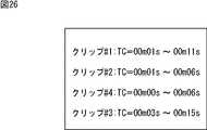
図26の編集リストでは、図21の編集リストのクリップ#2に対応する終了位置が9秒から6秒に変更され、クリップ#2とクリップ#3の間にクリップ#4が加えられる。また、クリップ#4に対応付けて、開始位置の0秒と終了位置の6秒が記述されている。 In the edit list in FIG. 26, the end position corresponding to clip # 2 in the edit list in FIG. 21 is changed from 9 seconds to 6 seconds, and
従って、ディスク編集装置110は、図26の編集リストを参照することにより、図25に示したように、編集クリップ#1、クリップ#2の1秒から6秒までの区間のデータである編集クリップ#2´、編集クリップ#4、編集クリップ#3を順に編集結果として再生する。 Therefore, the
以上のように、挿入モードがこじあけモードである場合、挿入区間に複数のクリップの一部または全部が編集クリップとして含まれる場合、編集結果における、挿入区間のイン点から、挿入区間内の先頭の編集クリップの終端までの区間に、挿入クリップが先頭から挿入され、その残りのデータが、先頭の編集クリップの終端と、その次の編集クリップの先頭の間に挿入される。 As described above, when the insertion mode is the pruning mode, when some or all of the plurality of clips are included as edit clips in the insertion section, from the In point of the insertion section in the editing result, the beginning of the insertion section The inserted clip is inserted from the beginning in the section up to the end of the edited clip, and the remaining data is inserted between the end of the first edited clip and the beginning of the next edited clip.
次に、図27を参照して、図19のディスク編集装置110が挿入クリップを挿入する挿入処理について説明する。この挿入処理は、例えば、ユーザが、挿入モードとイン点を指定し、挿入処理の開始を指令したとき、開始される。 Next, with reference to FIG. 27, an insertion process in which the
ステップS41において、図20の記録制御部132は、サーボ制御部15、信号処理部16、メモリコントローラ17、およびデータ変換部19を制御することにより、光ディスク11の未記録領域への挿入クリップの記録を開始する。 In step S41, the
ステップS41の処理後は、ステップS42に進み、記録制御部132は、指定部133から供給される挿入区間を表す情報に基づいて、挿入クリップを挿入区間分記録したかどうかを判定する。After the processing in step S41, the process proceeds to step S42, the
例えば、図21乃至図26で説明したように、編集クリップ#2の終端から3秒前の位置が挿入区間のイン点として、編集クリップ#3の先頭から3秒後の位置がアウト点として指定された場合、即ち、挿入区間が6秒間である場合、記録制御部62は、挿入クリップであるクリップ#4の先頭から6秒までの区間のデータを記録したどうかを判定する。 For example, as described in FIGS. 21 to 26, the
ステップS42において、挿入クリップを挿入区間分記録していないと判定された場合、記録制御部132は、挿入区間分記録したと判定されるまで待機する。 If it is determined in step S42 that the inserted clip has not been recorded for the inserted section, the
一方、ステップS42において、挿入クリップを挿入区間分記録したと判定された場合、記録制御部132は、記録を終了し、ステップS43に進む。 On the other hand, if it is determined in step S42 that the insertion clip has been recorded for the insertion interval, the
ステップS43において、判定部134は、指定部133から供給される挿入区間を表す情報と、編集リスト記憶部112に記憶されている編集リストとに基づいて、挿入区間に複数のクリップの一部または全部が編集クリップとして含まれているかどうかを判定し、その判定結果を編集リスト更新部135に供給する。 In step S <b> 43, the
ステップS43において、挿入区間に複数のクリップの一部または全部が編集クリップとして含まれていると判定された場合、
ステップS44に進み、編集リスト更新部135は、指定部133から供給される挿入区間を表す情報と判定部134からの判定結果とに基づいて、編集リスト記憶部112に記憶されている編集リストの挿入区間のイン点に対応するクリップを表す情報の直後に、挿入クリップを表す情報を追加する。また、編集リスト記憶部112は、挿入区間を表す情報に基づいて、挿入クリップを表す情報に対応付けて、その挿入クリップのうちの記録された挿入区間分のデータに対応する開始位置と終了位置を記述する。In step S43, when it is determined that some or all of the plurality of clips are included as edit clips in the insertion section,
Proceeding to step S44, the edit
ステップS44の処理後は、ステップS45に進み、編集リスト更新部135は、挿入区間を表す情報に基づいて、編集リストの、イン点に対応するクリップに対応付けられている終了位置を変更し、ステップS46に進む。 After the process of step S44, the process proceeds to step S45, and the edit
ステップS46において、編集リスト更新部135は、モード設定部131からの挿入モードを表す情報に基づいて、挿入モードがVTRライクモードであるかどうかを判定し、VTRライクモードではないと判定した場合、即ち挿入モードがこじあけモードである場合、処理を終了する。 In step S46, the edit
例えば、図25の例の場合、図21の編集リストのイン点に対応するクリップ#2を表す情報「クリップ#2」の直後に、挿入クリップであるクリップ#4を表す情報「クリップ#4」が追加され、その情報に対応して、挿入区間分のデータの開始位置である挿入クリップの先頭位置「0秒」と、終了位置「6秒」が記述される。そして、イン点に対応するクリップ#2の終了位置が、イン点に対応するクリップタイムコード「6秒」に変更され、その結果、編集リスト更新部135には、図26の編集リストが記憶される。 For example, in the case of the example of FIG. 25, immediately after the information “
一方、ステップS46において、挿入モードがVTRライクモードであると判定した場合、ステップS47に進み、編集リスト更新部135は、挿入区間を表す情報に基づいて、ステップS44で編集リストに追加された挿入クリップを表す情報の直後のクリップを表す情報に対応する開始位置を変更する。例えば、図24の例では、図26の編集リストにおいて、さらに、挿入クリップであるクリップ#4を表す情報「クリップ#4」の直後のクリップ#3を表す情報「クリップ#3」に対応する開始位置が、アウト点に対応するクリップタイムコード「6秒」に変更され、その結果、編集リスト更新部135には、図24の編集リストが記憶される。 On the other hand, when it is determined in step S46 that the insertion mode is the VTR-like mode, the process proceeds to step S47, and the edit
また、ステップS43において、挿入区間に複数のクリップの一部または全部が編集クリップとして含まれていないと判定された場合、ステップS48に進み、ステップS44と同様に、編集リスト更新部135は、指定部133から供給される挿入区間を表す情報と判定部134からの判定結果とに基づいて、編集リスト記憶部112に記憶されている編集リストの挿入区間のイン点に対応するクリップを表す情報の直後に、挿入クリップを表す情報を追加する。また、編集リスト記憶部112は、挿入区間を表す情報に基づいて、挿入クリップを表す情報に対応付けて、その挿入クリップのうちの記録された挿入区間分のデータに対応する開始位置と終了位置を記述する。 If it is determined in step S43 that some or all of the plurality of clips are not included in the insertion section as edit clips, the process proceeds to step S48, and the edit
ステップS48の処理後は、ステップS49に進み、編集リスト更新部135は、ステップS48で追加した挿入クリップを表す情報の直後に、イン点に対応するクリップと同一のクリップを表す情報を記述する。その結果、編集リストでは、イン点に対応するクリップを表す情報の直後に記述された挿入クリップを表す情報の直後に、再度イン点に対応するクリップを表す情報が記述される。 After the process of step S48, the process proceeds to step S49, and the edit
例えば、図22の例において、イン点とアウト点が、編集クリップ#2の開始位置から終了位置までの区間にある場合、編集クリップ#2に対応するクリップ#2を表す情報「クリップ#2」の直後に、挿入クリップであるクリップ#4を表す情報「クリップ#4」が記述され、その直後に、再度「クリップ#2」が記述される。 For example, in the example of FIG. 22, when the In point and the Out point are in the section from the start position to the end position of the
ステップS49の処理後は、ステップS50に進み、編集リスト更新部135は、挿入区間を表す情報に基づいて、イン点に対応するクリップを表す情報に対応して記述されている、そのクリップの開始位置または終了位置を変更する。具体的には、編集リスト更新部135は、ステップS49で追加する前に記述されていたイン点に対応するクリップの情報に対応する終了位置を、イン点に対応するクリップタイムコードに変更する。また、編集リスト更新部135は、ステップS49で追加されたイン点に対応するクリップを表す情報に対応する開始位置を、アウト点に対応するクリップタイムコードに変更する。ステップS50の処理後、処理は終了する。 After the processing of step S49, the process proceeds to step S50, and the edit
なお、本発明は、光ディスク以外のディスク状記録媒体にも適用することができる。 The present invention can also be applied to disc-shaped recording media other than optical discs.
以上のように、ディスク編集装置10または110は、挿入区間に、複数のクリップの一部または全部が含まれる場合、挿入クリップのうち、挿入区間のイン点から、そのイン点のデータを含むクリップの終端までの区間以外の区間に対応するデータを、光ディスク11の記録領域のうち、まだファイルが記録されていない領域である未記録領域に記録させるとともに、挿入クリップのうち、未記録領域に記録されるデータ以外のデータを光ディスク11の所定の領域に記録させ、イン点のデータを含むクリップの先頭からイン点までの区間、挿入クリップの順に再生した後、挿入前の再生順序が、イン点のデータを含むクリップの次のクリップを先頭から再生するように、インデックスファイルを生成するので、挿入区間に含まれる先頭のクリップが新たなクリップにより上書きされ、先頭のクリップ以外のファイルはそのまま保護されたように、編集結果を再生することができる。 As described above, when the insertion section includes a part or all of a plurality of clips, the
なお、本明細書において、プログラム記録媒体に格納されるプログラムを記述するステップは、記載された順序に沿って時系列的に行われる処理はもちろん、必ずしも時系列的に処理されなくとも、並列的あるいは個別に実行される処理をも含むものである。 In the present specification, the step of describing the program stored in the program recording medium is not limited to the processing performed in time series in the order described, but is not necessarily performed in time series. Or the process performed separately is also included.
また、本発明の実施の形態は、上述した実施の形態に限定されるものではなく、本発明の要旨を逸脱しない範囲において種々の変更が可能である。 The embodiments of the present invention are not limited to the above-described embodiments, and various modifications can be made without departing from the scope of the present invention.
10 ディスク編集装置, 24 ROM, 61 モード設定部,62 記録制御部, 63 指定部, 64 インデックス更新部, 110 ディスク編集装置, 131 モード設定部, 132 記録制御部, 133 指定部, 134 判定部, 135 編集リスト更新部 10 disc editing device, 24 ROM, 61 mode setting unit, 62 recording control unit, 63 specifying unit, 64 index updating unit, 110 disk editing device, 131 mode setting unit, 132 recording control unit, 133 specifying unit, 134 determining unit, 135 Edit List Update Department
Claims (4)
Translated fromJapanese前記所定の区間を挿入区間として指定する指定手段と、
前記新たなデータのうち、前記先頭のクリップに挿入されるデータである第1のデータを、前記編集対象のクリップ単位のデータを記録する記録媒体の前記挿入区間の開始位置から前記先頭のクリップの終端までのデータが記録される領域に上書きし、前記新たなデータのうちの前記第1のデータ以外のデータである第2のデータを、前記記録媒体の未記録領域に記録するように制御する記録制御手段と、
こじあけ編集後のデータの再生順序を表す順序情報を生成する生成手段と
を備え、
前記生成手段は、前記挿入区間の開始位置までの前記編集対象のクリップ単位のデータ、前記新たなデータ、前記先頭のクリップの終端より後ろの前記編集対象のクリップ単位のデータの順に再生するように、前記順序情報を生成し、
前記記録制御手段は、前記新たなデータを、前記先頭のクリップのこじあけ編集後のクリップとして記録させる
編集装置。Clips other than the firstclipamong the clips to be edited that include new data inserted in a predetermined section of theclip unitdata to be edited and include data before the insertion of the predetermined section after the new data In the editing device that performs the edit editing that connects the data of
Designating means for designating the predetermined section as an insertion section;
Among the newdata, the first data is data to be inserted intothe beginning oftheclip, from a starting position of the insertion section of the recording medium for recording data of the editedclip unit ofthe clip of theleading Overwrite the area where data up to the end is recorded, and control to record second data other than the first data in the new data in an unrecorded area of the recording medium. Recording control means;
Generating means for generating order information representing the reproduction order of the data after prying and editing,
The generation unit reproducesthe data inunits of the clip to beedited up to the start position of the insertion section, the new data, andthe data inunits of the clip to be edited after the end of theheadclip. , Generate the order information,
It said recording control means, wherein the new data, editing apparatus for recording theclip after editing pry-open of thebeginning oftheclip.
をさらに備え、
前記記録制御手段は、前記編集モードが前記こじあけモードである場合、前記新たなデータのうち、前記第1のデータを前記記録媒体の前記挿入区間の開始位置から前記先頭のクリップの終端までのデータが記録される領域に上書きし、前記第2のデータを前記記録媒体の未記録領域に記録するように制御し、前記編集モードが前記上書きモードである場合、前記新たなデータを前記記録媒体の前記挿入区間のデータが記録される領域に上書きするように制御し、
前記生成手段は、前記編集モードが前記こじあけモードである場合、前記挿入区間の開始位置までの前記編集対象のクリップ単位のデータ、前記新たなデータ、前記先頭のクリップの終端より後ろの前記編集対象のクリップ単位のデータの順に再生するように、前記順序情報を生成し、前記編集モードが前記上書きモードである場合、前記挿入区間の開始位置までの前記編集対象のクリップ単位のデータ、前記新たなデータ、前記挿入区間の終了位置からの前記編集対象のクリップ単位のデータの順に再生するように、前記順序情報を生成し、
前記記録制御手段は、前記編集モードがこじあけモードである場合、前記新たなデータを、前記先頭のクリップのこじあけ編集後のクリップとして記録させる
請求項1に記載の編集装置。Setting means for setting an edit mode to a pruning mode for performing the pruning editing or an overwriting editing mode for performing overwriting editing, which is an editing for overwriting the new data in the insertion section of the data of theclip unit to be edited. In addition,
The recording control means may control, when the editing mode is the pry-open mode, among the new data, the data of the first data from the start position of the insertion section of the recording medium to the end of thebeginning oftheclip Is overwritten in the area to be recorded, and the second data is recorded in an unrecorded area of the recording medium. When the editing mode is the overwrite mode, the new data is stored in the recording medium. Control to overwrite the area where the data of the insertion section is recorded,
When the editing mode is the pruning mode, the generating means is the editingunit clip data up to the start position of the insertion section, the new data, theediting target after the end of thetopclip If the editing mode is the overwrite mode,the clip unit data to beedited up to the start position of the insertion section, the new data is generated. The order information is generated so that data is reproduced in the order ofthe clip unit data to beedited from the end position of the insertion section,
The recording control means may control, when the editing mode is the pry-open mode, the new data, the editing apparatus according to claim 1 which is recorded asa clip after editing pry-open of thebeginning oftheclip.
前記所定の区間を挿入区間として指定し、
前記新たなデータのうち、前記先頭のクリップに挿入されるデータである第1のデータを、前記先頭のクリップのこじあけ編集後のクリップとして、前記編集対象のクリップ単位のデータを記録する記録媒体の前記挿入区間の開始位置から前記先頭のクリップの終端までのデータが記録される領域に上書きし、前記新たなデータのうちの前記第1のデータ以外のデータである第2のデータを、前記先頭のクリップのこじあけ編集後のクリップとして前記記録媒体の未記録領域に記録するように制御し、
前記挿入区間の開始位置までの前記編集対象のクリップ単位のデータ、前記新たなデータ、前記先頭のクリップの終端より後ろの前記編集対象のクリップ単位のデータの順に再生するように、こじあけ編集後のデータの再生順序を表す順序情報を生成する
ステップを含む編集方法。Clips other than the firstclipamong the clips to be edited that include new data inserted in a predetermined section of theclip unitdata to be edited and include data before the insertion of the predetermined section after the new data In the editing method of the editing device that performs the edit editing that connects the data of
Designate the predetermined section as an insertion section,
Among the newdata, the first data is data to be inserted intothe beginning oftheclip, as aclip after editing pry-open of thebeginning oftheclip, the recording medium for recording data of the editedclip units Overwrite the area where data from the start position of the insertion section to the end of theheadclip is recorded, and add second data that is data other than the first data of the new data to thehead. Control to record in the unrecorded area of the recording medium asa clip after editing
The dataafter clip editing is reproduced so thatthe data ofthe clip unit to beedited up to the start position of the insertion section, the new data, andthe data ofthe clip unit of the edit target after the end of theheadclip are played in this order. An editing method including a step of generating order information representing a data reproduction order.
前記所定の区間を挿入区間として指定し、
前記新たなデータのうち、前記先頭のクリップに挿入されるデータである第1のデータを、前記先頭のクリップのこじあけ編集後のクリップとして、前記編集対象のクリップ単位のデータを記録する記録媒体の前記挿入区間の開始位置から前記先頭のクリップの終端までのデータが記録される領域に上書きし、前記新たなデータのうちの前記第1のデータ以外のデータである第2のデータを、前記先頭のクリップのこじあけ編集後のクリップとして前記記録媒体の未記録領域に記録するように制御し、
前記挿入区間の開始位置までの前記編集対象のクリップ単位のデータ、前記新たなデータ、前記先頭のクリップの終端より後ろの前記編集対象のクリップ単位のデータの順に再生するように、こじあけ編集後のデータの再生順序を表す順序情報を生成する
ステップを含むプログラム。Clips other than the firstclipamong the clips to be edited that include new data inserted in a predetermined section of theclip unitdata to be edited and include data before the insertion of the predetermined section after the new data In the program that causes the computer to perform the editing process that performs editing that connects the data of
Designate the predetermined section as an insertion section,
Among the newdata, the first data is data to be inserted intothe beginning oftheclip, as aclip after editing pry-open of thebeginning oftheclip, the recording medium for recording data of the editedclip units Overwrite the area where data from the start position of the insertion section to the end of theheadclip is recorded, and add second data that is data other than the first data of the new data to thehead. Control to record in the unrecorded area of the recording medium asa clip after editing
The dataafter clip editing is reproduced so thatthe data ofthe clip unit to beedited up to the start position of the insertion section, the new data, andthe data ofthe clip unit of the edit target after the end of theheadclip are played in this order. A program including a step of generating order information representing a data playback order.
Priority Applications (5)
| Application Number | Priority Date | Filing Date | Title |
|---|---|---|---|
| JP2006117972AJP4645910B2 (en) | 2006-04-21 | 2006-04-21 | Editing apparatus, editing method, and program |
| US11/736,328US8301015B2 (en) | 2006-04-21 | 2007-04-17 | Recording control apparatus, recording control method, and program |
| EP07106433AEP1847998A1 (en) | 2006-04-21 | 2007-04-18 | Recording control apparatus, recording control method, and program |
| KR1020070038736AKR20070104281A (en) | 2006-04-21 | 2007-04-20 | Record control apparatus and record control method, and program |
| CN200710101274XACN101060000B (en) | 2006-04-21 | 2007-04-20 | Recording control apparatus and recording control method, and program |
Applications Claiming Priority (1)
| Application Number | Priority Date | Filing Date | Title |
|---|---|---|---|
| JP2006117972AJP4645910B2 (en) | 2006-04-21 | 2006-04-21 | Editing apparatus, editing method, and program |
Publications (3)
| Publication Number | Publication Date |
|---|---|
| JP2007293946A JP2007293946A (en) | 2007-11-08 |
| JP2007293946A5 JP2007293946A5 (en) | 2009-02-05 |
| JP4645910B2true JP4645910B2 (en) | 2011-03-09 |
Family
ID=38308657
Family Applications (1)
| Application Number | Title | Priority Date | Filing Date |
|---|---|---|---|
| JP2006117972AExpired - Fee RelatedJP4645910B2 (en) | 2006-04-21 | 2006-04-21 | Editing apparatus, editing method, and program |
Country Status (5)
| Country | Link |
|---|---|
| US (1) | US8301015B2 (en) |
| EP (1) | EP1847998A1 (en) |
| JP (1) | JP4645910B2 (en) |
| KR (1) | KR20070104281A (en) |
| CN (1) | CN101060000B (en) |
Families Citing this family (2)
| Publication number | Priority date | Publication date | Assignee | Title |
|---|---|---|---|---|
| CN102959707B (en)* | 2011-06-30 | 2016-09-28 | 株式会社日本有机雷特显示器 | Display panel and method for manufacturing display panel |
| JP5901364B2 (en)* | 2012-03-09 | 2016-04-06 | キヤノン株式会社 | REPRODUCTION CONTROL DEVICE AND REPRODUCTION CONTROL METHOD |
Family Cites Families (18)
| Publication number | Priority date | Publication date | Assignee | Title |
|---|---|---|---|---|
| JP3067801B2 (en) | 1992-04-10 | 2000-07-24 | アヴィッド・テクノロジー・インコーポレーテッド | Digital audio workstation providing digital storage and display of video information |
| US5339393A (en) | 1993-04-15 | 1994-08-16 | Sony Electronics, Inc. | Graphical user interface for displaying available source material for editing |
| JPH08297956A (en)* | 1995-04-27 | 1996-11-12 | Sony Corp | Recorder |
| US5760767A (en) | 1995-10-26 | 1998-06-02 | Sony Corporation | Method and apparatus for displaying in and out points during video editing |
| JPH10162560A (en)* | 1996-12-04 | 1998-06-19 | Matsushita Electric Ind Co Ltd | Video editing method and non-linear video editing device |
| JP4404233B2 (en) | 1996-12-09 | 2010-01-27 | ソニー株式会社 | Editing apparatus and data transmission method |
| JPH11120746A (en)* | 1997-10-13 | 1999-04-30 | Nippon Columbia Co Ltd | Optical disk recording and reproducing device |
| EP0949615A4 (en) | 1997-10-28 | 2006-08-23 | Sony Corp | Data recording apparatus and data recording method, and data editing apparatus and data editing method |
| JP3895849B2 (en) | 1997-11-11 | 2007-03-22 | トムソン ライセンシング | Non-linear video editing system |
| JP3895848B2 (en)* | 1997-11-11 | 2007-03-22 | トムソン ライセンシング | Non-linear video editing system |
| JPH11203837A (en) | 1998-01-16 | 1999-07-30 | Sony Corp | Editing system and method therefor |
| WO2000028543A1 (en) | 1998-11-10 | 2000-05-18 | Sony Corporation | Edit data creating device and edit data creating method |
| JP2000182360A (en) | 1998-12-15 | 2000-06-30 | Matsushita Electric Ind Co Ltd | Video editing apparatus and video editing method |
| JP2000285653A (en) | 1999-03-29 | 2000-10-13 | Sony Corp | Information recording and reproducing device |
| JP2001143447A (en) | 1999-11-16 | 2001-05-25 | Sony Corp | Device and method for editing data and data recording and reproducing device |
| GB2356734B (en) | 1999-11-26 | 2003-11-05 | Sony Uk Ltd | Editing of recorded material |
| JP4264829B2 (en)* | 2004-10-06 | 2009-05-20 | ソニー株式会社 | Information processing apparatus and method, and program |
| JP4144583B2 (en)* | 2004-10-06 | 2008-09-03 | ソニー株式会社 | Recording / reproducing apparatus and editing method |
- 2006
- 2006-04-21JPJP2006117972Apatent/JP4645910B2/ennot_activeExpired - Fee Related
- 2007
- 2007-04-17USUS11/736,328patent/US8301015B2/ennot_activeExpired - Fee Related
- 2007-04-18EPEP07106433Apatent/EP1847998A1/ennot_activeWithdrawn
- 2007-04-20CNCN200710101274XApatent/CN101060000B/ennot_activeExpired - Fee Related
- 2007-04-20KRKR1020070038736Apatent/KR20070104281A/ennot_activeAbandoned
Also Published As
| Publication number | Publication date |
|---|---|
| US8301015B2 (en) | 2012-10-30 |
| CN101060000B (en) | 2010-06-02 |
| US20070248325A1 (en) | 2007-10-25 |
| JP2007293946A (en) | 2007-11-08 |
| CN101060000A (en) | 2007-10-24 |
| EP1847998A1 (en) | 2007-10-24 |
| KR20070104281A (en) | 2007-10-25 |
Similar Documents
| Publication | Publication Date | Title |
|---|---|---|
| JP4865884B2 (en) | Information recording medium | |
| JP3861261B2 (en) | Optical disc apparatus, optical disc recording method, optical disc recording method program, and recording medium storing optical disc recording method program | |
| JP3921593B2 (en) | Information processing apparatus and method, program storage medium, program, and information recording medium | |
| JP4645910B2 (en) | Editing apparatus, editing method, and program | |
| JP3610975B2 (en) | Recording apparatus and method | |
| RU2429552C2 (en) | Video recording device and method, data medium storing programme for video recording method | |
| JP3873921B2 (en) | Recording apparatus and method | |
| JP3760467B2 (en) | Content reproduction apparatus and method, recording medium, and program | |
| US8682141B2 (en) | Video and audio recording apparatus and editing method | |
| JP2007311003A (en) | Recording and reproducing device | |
| JP2004355767A (en) | Playback device | |
| JP4028246B2 (en) | Information recording and editing apparatus and information recording medium | |
| WO2005029495A1 (en) | Recorder, recording method and recording medium where program is recorded | |
| JP2000215648A (en) | Recording device | |
| JPH09154099A (en) | Video editing device | |
| JP4179030B2 (en) | Recording apparatus and method, and reproducing apparatus and method | |
| JP3824622B2 (en) | Optical disc playback method and playback apparatus | |
| JP4678523B2 (en) | Recording control apparatus, recording control method, and program | |
| JP4564021B2 (en) | Information recording medium | |
| JP3681370B2 (en) | Optical disc recording method and recording apparatus, and reproducing method and reproducing apparatus | |
| JP2006244669A (en) | Optical disc playback apparatus and control program for controlling optical disc playback apparatus | |
| JP2007157256A (en) | Recording system | |
| JP2004310833A (en) | Recorder and recording method | |
| JP2004310832A (en) | Recording device and method | |
| JP2005004810A (en) | Information recording / reproducing apparatus and method thereof |
Legal Events
| Date | Code | Title | Description |
|---|---|---|---|
| A521 | Request for written amendment filed | Free format text:JAPANESE INTERMEDIATE CODE: A523 Effective date:20081212 | |
| A621 | Written request for application examination | Free format text:JAPANESE INTERMEDIATE CODE: A621 Effective date:20081212 | |
| A977 | Report on retrieval | Free format text:JAPANESE INTERMEDIATE CODE: A971007 Effective date:20100701 | |
| A131 | Notification of reasons for refusal | Free format text:JAPANESE INTERMEDIATE CODE: A131 Effective date:20100713 | |
| A521 | Request for written amendment filed | Free format text:JAPANESE INTERMEDIATE CODE: A523 Effective date:20100906 | |
| A131 | Notification of reasons for refusal | Free format text:JAPANESE INTERMEDIATE CODE: A131 Effective date:20100930 | |
| A521 | Request for written amendment filed | Free format text:JAPANESE INTERMEDIATE CODE: A523 Effective date:20101101 | |
| TRDD | Decision of grant or rejection written | ||
| A01 | Written decision to grant a patent or to grant a registration (utility model) | Free format text:JAPANESE INTERMEDIATE CODE: A01 Effective date:20101111 | |
| A01 | Written decision to grant a patent or to grant a registration (utility model) | Free format text:JAPANESE INTERMEDIATE CODE: A01 | |
| A61 | First payment of annual fees (during grant procedure) | Free format text:JAPANESE INTERMEDIATE CODE: A61 Effective date:20101124 | |
| FPAY | Renewal fee payment (event date is renewal date of database) | Free format text:PAYMENT UNTIL: 20131217 Year of fee payment:3 | |
| FPAY | Renewal fee payment (event date is renewal date of database) | Free format text:PAYMENT UNTIL: 20131217 Year of fee payment:3 | |
| LAPS | Cancellation because of no payment of annual fees |