JP4645781B2 - Substrate processing method and substrate processing apparatus - Google Patents
Substrate processing method and substrate processing apparatusDownload PDFInfo
- Publication number
- JP4645781B2 JP4645781B2JP2001033227AJP2001033227AJP4645781B2JP 4645781 B2JP4645781 B2JP 4645781B2JP 2001033227 AJP2001033227 AJP 2001033227AJP 2001033227 AJP2001033227 AJP 2001033227AJP 4645781 B2JP4645781 B2JP 4645781B2
- Authority
- JP
- Japan
- Prior art keywords
- substrate
- water
- drying
- active species
- cleaning
- Prior art date
- Legal status (The legal status is an assumption and is not a legal conclusion. Google has not performed a legal analysis and makes no representation as to the accuracy of the status listed.)
- Expired - Fee Related
Links
Images


Landscapes
- Cleaning By Liquid Or Steam (AREA)
- Physical Or Chemical Processes And Apparatus (AREA)
- Cleaning Or Drying Semiconductors (AREA)
- Liquid Crystal (AREA)
- Cleaning In General (AREA)
Description
Translated fromJapanese【0001】
【発明の属する技術分野】
本発明は、液晶パネル基板、半導体ウェハ、磁気ディスク基板、光ディスク基板、PDPパネル等のように、ガラス、半導体、樹脂、セラミックス、金属等や、それらの複合された基板表面に紫外光を照射して、洗浄,エッチング等の処理を行う紫外光照射による基板処理方法及び基板処理装置に関するものである。
【0002】
【従来の技術】
例えば、液晶パネルを構成する透明基板を構成するTFT基板は、その表面に成膜手段により透明電極等を含む回路パターンが形成される。この基板製造工程において、基板表面に対して、洗浄,現像液の塗布,露光,剥離液の塗布及びその除去等といった工程が繰り返される。これらの工程において、基板表面から無機物や有機物を取り除き、基板の接触角を小さくする等の処理を行うための工程、例えば洗浄工程等は基板表面に液を供給して行う、所謂ウエットプロセス方式で行うのが一般的である。しかしながら、近年においては、このような処理を基板に対して紫外光を照射することによるドライプロセスでも行われるようになってきている。
【0003】
特開平5−224167号公報には、液晶パネルを構成するガラス基板の洗浄方法として、洗浄液を用いたウェットプロセスを行うに先立って、基板に紫外光を照射する処理を行うように構成したものが開示されている。この公知の洗浄方法では、洗浄液を噴射して基板を洗浄する前工程として、基板の表面に低圧水銀ランプからの紫外光を照射する。この紫外光の照射によって、基板の表面に付着している有機物を化学的に除去すると共に、この表面の濡れ性を改善して、即ち接触角を小さくすることにより、シャワー等による洗浄時に無機物の汚れを効率的に取り除くようにしたものである。ここで、低圧水銀ランプから照射される紫外光は、その波長が概略185nm及び254nmにピークを持つものであり、このようなピーク波長特性を有する紫外光により基板表面に付着した有機物を除去することができる。
【0004】
この紫外光照射による有機物洗浄のメカニズムとしては、紫外光の照射エネルギで有機物における化学結合を分解することにより低分子化させると共に、分解生成物を活性化させる。また、これと同時に、空気中の酸素が紫外光を吸収することによりオゾンが発生し、さらにこのオゾンが活性酸素に変換されるから、活性化した有機汚染物は、活性酸素との酸化分解反応によって最終的にはCOx ,H2 O,NOx 等の揮発物質に変換され、この揮発物質は空気中に放出されるようにして除去される。しかしながら、低圧水銀ランプから照射される紫外光の波長は短波長側では185nmであるから、基板に付着した有機物であっても、2重結合等のように化学結合エネルギの強いものを分解できない場合がある。従って、基板をより完全に洗浄するには、さらに短い波長の紫外光を照射しなければならない。
【0005】
以上の点を勘案して、誘電体バリア放電ランプ(以下、単に放電ランプという)を用い、この放電ランプから真空紫外光を基板表面に照射して、ワークをドライ洗浄する方式が特開平7−196303号公報に提案されている。
【0006】
ここで、この特開平7−196303号公報に示された洗浄方法は、真空紫外光による光化学反応により活性酸化性分解物を生じさせると共に、基板の表面に付着している有機汚染物を除去するものである。つまり、放電ランプから照射される172nmの波長の紫外光で有機物を構成する化学結合を分解することにより低分子化させ、かつこの分解生成物を活性化させる。また、これと同時に空気中の酸素が紫外光の作用で分解されて活性酸素に変換されるから、活性化した有機汚染物は、この活性酸素との酸化反応によって最終的には、COx ,H2 O,NOx 等の揮発物質に変換され空気中に放出されるように除去され、その結果基板の接触角が小さくなる。
【0007】
【発明が解決しようとする課題】
ところで、空気中の酸素を分解する際に紫外光のエネルギが消費されるために、放電ランプと基板とが離間していると、その間の間隔が大きくなればなるほど、その間の空気層の厚みが大きくなって、基板表面に到達する紫外光のエネルギが指数関数的に減衰する。その結果、基板表面の有機物に対する活性化能力及び基板表面近傍での活性酸素の発生能力が低下し、有機物除去能力も著しく低下するという欠点がある。従って、紫外光は基板の直近位置に到達するまでは、酸素と接触しないようにするのが望ましい。このためには、放電ランプが設けられているランプハウスの内部を不活性ガス雰囲気とするために、ランプハウスを密閉しなければならない。しかも、基板に対して紫外光を照射できるようにするには、ランプハウスに紫外光が出射される窓ガラスを装着した透明窓を設けることになる。この窓ガラスは紫外光の透過効率及び耐久性等の観点から、石英ガラス等といった高価な素材を用いなければならず、しかも耐久性が優れているものの、長時間紫外光が照射されるとやはり劣化することから、この窓ガラスをある程度の頻度で交換しなければならない等、メンテナンスの面等からも問題がある。
【0008】
また、酸素を含む流体に真空紫外光を照射することにより生成されるのは活性酸化性分解物である。従って、基板の表面に付着している有機物とは酸化反応しか生じることはないので、基板表面から除去できる有機物の種類等によっては効率的に除去できない場合がある等といった問題点もある。
【0009】
本発明は以上の点に鑑みてなされたものであって、その目的とするところは、放電ランプから照射された紫外光が基板の直近位置に至るまでできるだけ減衰しないようになし、かつ基板表面に対する処理精度及び処理効率を改善することにある。
【0010】
【課題を解決するための手段】
前述した目的を達成するために、本発明の基板処理方法は、基板表面の全面に水を供給して行うウエット処理工程と、前記基板表面の吸着水を残し、水膜及び水滴を除去する乾燥工程と、前記基板を処理チャンバ内に搬入し、この処理チャンバ内を不活性ガスの雰囲気とした状態で、前記基板表面に紫外光を照射することによって、前記基板の表面の吸着水から還元性の活性種[H・]及び酸化性の活性種[・OH]を生成させると共に、これら活性種[H・],活性種[・OH]と前記基板表面の有機物とを反応させるようにして前記基板の表面処理を行う表面処理工程と、前記表面処理工程の後に前記基板を高温乾燥する基板高温乾燥工程とを含むものであることをその特徴とするものである。
【0011】
まず、紫外光により生成され、基板表面に付着する有機物と反応する活性種を生成する物質として酸素ではなく水としている。紫外光の放射線の作用によって水を分解すると、酸化性の活性種[・OH]だけでなく、還元性の活性種[H・]が生成される。従って、基板表面に付着している有機物に対しては、酸化反応だけでなく、還元反応も生じることになるので、より有効に有機物を分解・除去できることになる。しかも、基板表面における吸着水を用いる。従って、放電ランプをチャンバ内に設置して、このチャンバ内全体を不活性ガスの雰囲気下に置けば良く、酸素等を導入する必要はなくなる。その結果、紫外光の減衰を著しく抑制できる。しかも、水の分解反応は基板の表面における直近位置で発生するので、紫外光のエネルギによって、化学結合を分解することにより低分子化された有機物と反応する機会が高められる。従って、基板に対する処理精度及び処理効率が極めて高くなる。
【0012】
ここで、ウエット処理工程としては、洗浄水(好ましくは純水)を基板表面に供給して行うウエット洗浄工程がある。従って、このウエット洗浄工程と紫外光による表面処理工程とを組み合わせると、極めて高い洗浄性を発揮する。ここで、ウエット洗浄工程の具体例としては、シャワー洗浄,洗浄槽へのディッピング,スクラブ洗浄等があり、いずれの場合においても、洗浄水を超音波加振することもでき、このように超音波加振を行うと、基板表面に付着している微細な無機物粒子等の除去をより効率的に行える。
【0013】
ウエット処理を行った後には、基板表面に水が吸着するが、基板表面に水膜が形成され、また水滴が付着している。そこで、基板表面から水膜や水滴を除去する必要がある。ウエット処理工程の次に乾燥工程を設けたのは、このためである。ただし、乾燥工程では、基板表面における吸着水は除去されないように保持する必要がある。従って、加熱乾燥は行わず、エアナイフを用いた乾燥、さらにはスピン乾燥等が好適である。
【0014】
酸化性の活性種[・OH]及び還元性の活性種[H・]の生成は、基板の吸着水を利用して行うことから、放電ランプによる紫外光の照射は不活性ガス雰囲気下で行うことができる。これによって、紫外光が基板直近位置に至るまでに生じる減衰を極力抑制できる。従って、放電ランプを密閉する必要がなく、開放空間で、あるいはこの放電ランプを反射部材で形成したランプハウスに収容させて、紫外光を反射部材に反射させることにより、紫外光を基板表面に向けて集光させるようにすることができる。そして、ランプハウスとしては、窓ガラスを設けるようにしても良いが、この窓ガラスは石英ガラス等というように、高価であり、また劣化が生じる材質のものを用いることから、この窓ガラスを設けないようにすることもできる。なお、放電ランプが置かれる空間には、希薄な空気や、酸素等を存在させるのが望ましい。
【0015】
前述したように、乾燥工程では基板表面から吸着水を除去しないことから、基板は完全に乾燥してはいない。そこで、完全な乾燥が必要な場合には、表面処理工程を経た後に、基板を加熱炉等で高温乾燥させるようにすれば良い。
【0016】
また、本発明の基板処理装置は、基板の搬送経路に配置され、前記基板表面の全面に水を供給するウエット処理手段を備えた洗浄水供給チャンバと、前記洗浄水供給チャンバの下流側に配置され、前記ウエット処理手段により基板表面に付着した水膜及び水滴は除去し、表面の吸着水を残すように乾燥する基板乾燥手段を設けた乾燥チャンバと、前記乾燥チャンバの下流側に配置され、誘電体バリア放電ランプが装着され、前記基板を不活性ガスの雰囲気下で、前記誘電体バリア放電ランプから照射される紫外光によって、前記基板の表面の吸着水から還元性の活性種[H・]及び酸化性の活性種[・OH]を生成させると共に、これら活性種[H・],活性種[・OH]と前記基板表面の有機物とを反応させるようにして前記基板の表面処理を行う基板表面処理手段を備えた処理チャンバと、前記処理チャンバの下流側に設けられ、前記基板を高温乾燥する高温加熱乾燥チャンバとを備える構成としたことをその特徴とするものである。
【0017】
【発明の実施の形態】
以下、図面に基づいて本発明の実施の形態について説明する。なお、以下においては、基板処理として、基板の洗浄を行うものとして説明するが、これ以外の処理を行う場合にも適用することもできる。
【0018】
まず、図1に本発明の基板処理方法を実施するための装置の概略構成を示す。
洗浄が行われる対象物としての基板Sは、例えばガラス、半導体、合成樹脂、セラミックス、金属等で形成した薄板からなり、平面形状としては、四角形乃至円形等である。本発明による基板の処理を行う工程は4つの工程で構成される。最初の工程はウエット洗浄手段を備えたウエット洗浄工程1であり、次いで第2番目の工程では基板Sを乾燥させる基板乾燥工程2であり、第3番目のステージは基板表面処理手段を設けた表面処理工程、即ちドライ洗浄工程3である。さらに、ドライ洗浄工程3の後に高温乾燥工程4が続くことになる。そして、これら各工程1〜4に基板Sを順次搬送するために、ローラコンベアやベルトコンベア等からなり、基板Sの搬送手段としての搬送コンベア10を備えている。
【0019】
まず、第1番目の処理工程であるウェット洗浄工程1は基板Sの表面(一側の表面または両面、以下同じ)を洗浄するものであり、洗浄方式としては、例えばシャワー洗浄や、洗浄水槽内に浸漬させて行うディッピング洗浄等があり、またシャワー洗浄やディッピング洗浄時にブラシを基板Sの表面に摺接させて行うスクラブ洗浄が含まれる。そして、シャワー洗浄,ディッピング洗浄を行う際には、適宜洗浄水を超音波加振することもできる。なお、いずれのタイプであっても、洗浄水としては、実質的に不純物を含まない純水を用いる必要がある。図1にはシャワー洗浄手段を設けたものが示されている。シャワー洗浄手段は、搬送コンベア10の上部(または上部及び下部)に設けられ、少なくとも基板Sの搬送方向と直交する方向の全長に及ぶ長さを有する洗浄水供給パイプ11を有し、この洗浄水供給パイプ11には多数の噴射口12が穿設されている。洗浄水供給パイプ11は、搬送コンベア10の搬送方向と直交する方向に向けて1本乃至複数本設けられている。
【0020】
従って、搬送コンベア10により搬送される基板Sは、まずその表面がウエット洗浄されることになる。その結果、基板Sの表面に付着している無機物の粒子が洗い流されることになる。そして、この無機物の除去をより確実かつ効率的に、しかも完全に行うには、洗浄水供給パイプ11から噴射される洗浄水を超音波加振するのが望ましい。ここで、基板Sに付着する汚損物としては、前述した無機物だけでなく、有機汚損物も含まれるが、このウエット洗浄工程1では必ずしも有機汚損物を完全に除去する必要はない。
【0021】
ここで、基板Sは搬送コンベア10により水平状態で搬送するように構成しても良いが、図2に示したように、ウェット洗浄工程1では、搬送方向と直交する方向に所定角度傾けるようにして基板Sを搬送する傾斜搬送コンベア10aを設けて、この傾斜搬送コンベア10aにより基板Sを傾斜状態で搬送する間に、シャワー洗浄手段により超音波で加振した純水を噴射させるようにすることもできる。従って、この場合のシャワー洗浄手段は、主支持部材13に所定数の取付部材14,14,・・・を角度調整可能に装着し、これら各取付部材14に洗浄水噴射器15を装着するように構成することができる。主支持部材13はシャワー洗浄手段全体を、傾斜搬送コンベア10aにより搬送される基板Sの角度に応じて、所定角度傾斜させるようになし、また取付部材14は、個々の洗浄水噴射器15の基板Sに対する角度を微調整できるようにしている。
【0022】
以上のように、ウエット洗浄工程1において、基板Sを傾斜させることによって、洗浄水噴射器15から噴射されて、基板Sに適用された洗浄水は、この基板Sの傾斜に沿って迅速に排出される。これによって、基板Sには常に新鮮な洗浄水が供給されて、洗浄効率が向上すると共に、このウエット洗浄工程1を通過した後には、基板Sの表面には実質的に洗浄水が残存していない状態となる。
【0023】
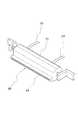
次に、乾燥工程2では、前述したウエット洗浄工程1で供給され、基板Sの表面に付着している洗浄水を取り除いて乾燥させる。従って、ウエット洗浄工程1では、図2に示した傾斜搬送コンベア10aを設けるようにしている場合には、この乾燥工程2に入る前の段階で水平搬送状態に戻すようにする。ここで、基板Sの乾燥方式としては種々のものが知られている。基板Sを高速回転させて行うスピン乾燥等もあるが、図示した乾燥方式では、エアナイフ効果による乾燥を行うようにしたものが示されている。そこで、図3及び図4にエアナイフ効果を用いた基板乾燥手段の具体的な構成を示す。
【0024】
これらの図において、20はエアナイフノズルを示し、このエアナイフノズル20は、細長い長尺のケーシング21を有し、このケーシング21内には加圧したエアが導入される加圧エアチャンバ22(図3に符号22U,22Lで示されている。)が形成されている。そして、ケーシング21の側面部にはエア流出通路23が形成されており、その先端は細いスリット状のノズル口24となっている。エア流出通路23(図3に符号23U,23Lで示されている。)は、ノズル口24からエアが噴出する際に細いライン状となるように整流するために必要な通路長を有するものである。さらに、ケーシング21には加圧エアチャンバ22内に加圧エアを供給するためのエア供給配管25が1乃至複数箇所接続されている。そして、エアナイフノズル20は乾燥チャンバ26内に配置されており、この乾燥チャンバ26の上流側には純水供給チャンバ27を設ける。そして、乾燥チャンバ26を陽圧状態に保ち、純水供給チャンバ27を陰圧に保つ。
【0025】
ここで、基板Sの表裏両面を乾燥させるために、エアナイフノズル20は基板Sの搬送経路を挟んで上下に配置されている。そこで、上部側、つまり表面側を乾燥させるエアナイフノズルを20U,下部側、つまり裏面側を乾燥させるエアナイフノズルを20Lとし、それらのノズル口を24U,24Lとしたときに、エアナイフノズル20U及び20Lは基板Sの表裏両面から等しい距離だけ離間し、かつこれら各面と平行な面に位置している。また、エアナイフノズル20Uにおけるノズル口24Uから噴射されるエアの俯角と、エアナイフノズル20Lのノズル口24Lの仰角とは同じであって、コンベア手段10による基板Sの搬送方向の後方側に向けて所定の角度を持つようにして配置されている。また、エアナイフノズル20U及び20Lは、基板Sの搬送方向と直交する方向に配置されているのではなく、前述した面内で所定角度θだけ傾斜させて配置されている。さらに、エアナイフノズル20U,20Lのノズル口24U,24Lは、コンベア手段10上を搬送される基板Sの表面に対して、その搬送方向と交差する方向の全長に及ぶようになっている。
【0026】
従って、搬送コンベア10で搬送され、前工程であるウエット洗浄工程1で基板Sの表面に付着する汚損物、特に無機物の粒子等が除去された基板Sがエアナイフ乾燥工程2に移行すると、エアナイフノズル20の作用で基板Sの表面に付着している水分が除去されるように乾燥される。このために、このエアナイフ乾燥工程2を構成するエアナイフノズル20から加圧エアを噴出させる状態としておき、搬送コンベア10により搬送される基板Sがエアナイフノズル20による加圧エアの噴射領域に突入する。エアナイフノズル20からは薄いカーテン状の加圧エアが噴出しており、しかも基板Sの表面に対して所定の角度をもって入射されるようになっており、この角度を制御することによって、基板Sの表面に付着している洗浄水が剥離され、基板Sの搬送方向後方に向けて押し出される。その結果、基板Sの表面から洗浄液が排出される。
【0027】
ここで、エアナイフノズル20により基板Sの表面から除去されるのは、水膜及び水滴であって、水の分子が基板Sの表面に吸着された状態で保持される。つまり、基板Sの表面には吸着水を残存させるようにして、その乾燥が行われ、この吸着水は基板Sの表面全体にわたってほぼ均一に分布する状態を保持させる。水膜や水滴を除去するのは、後述するドライ洗浄工程3において、基板Sに照射される紫外光が基板Sの表面全体に及ぶようにするためである。もし、水滴等が付着していると、その部分に対するドライ洗浄が不十分になるからである。
【0028】
また、エアナイフノズル20が配置されている乾燥チャンバ26を陽圧に保ち、その上流側に陰圧状態とした純水供給チャンバ27を設けたのは、乾燥チャンバ26に基板Sが搬入される際に、その表面が部分的に乾燥しないようにするためであり、またエアナイフノズル20の作用で基板Sを乾燥させる際に生じるミスト等が基板Sに再付着しないようにするためである。
【0029】
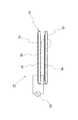
以上のように、エアナイフノズル20の作用によって乾燥され、なお表面に吸着水が付着している基板Sは搬送コンベア10によりさらに搬送されて、ドライ洗浄工程3に移行する。ここで、ドライ洗浄工程3では、基板Sに対して紫外線照射による表面洗浄が行われる。このドライ洗浄工程3は、基板表面処理手段としての放電ランプを含むものである。そこで、図5及び図6にこの放電ランプの概略構成を示す。
【0030】
即ち、同図において、31は放電ランプである。放電ランプ31は共に石英ガラスで一体的に形成した内管部32と外管部33とから円筒状に形成した石英ガラス管34で構成される。この石英ガラス管34の内部は密閉された放電空間35となる。内管部32の内側には円筒状の金属板からなる金属電極36がこの内管部32に固着して設けられている。また、外管部33の外周面には、金網電極37が設けられている。そして、これら金属電極36と金網電極37との間に交流電源38が接続されている。さらに、内管部32の内側は、金属電極36を冷却するための冷却用流体(例えば冷却水)の通路として利用される。
【0031】
石英ガラス管34の内部には放電ガスが封入されており、金属電極36と金網電極37との間に交流の高電圧を印加すると、内管部32と外管部33との誘電体間に放電プラズマ(誘電体バリア放電)が発生し、この放電プラズマにより放電ガスの原子が励起されて、プラズマ放電状態となる。そして、このプラズマ放電状態から基底状態に戻る際に、プラズマ放電発光が生じる。この時の発光スペクトルは、石英ガラス管34内に封入された放電ガスにより異なるが、キセノン(Xe)ガスを用いると、172nmに中心波長を持つ単色光となる。また、アルゴン(Ar)ガスを放電ガスとして用いれば、発光波長の中心は低圧水銀ランプの波長より短い126nmとなる。そして、金属電極36は反射板として機能し、また金網電極7は実質的に透明電極として機能するから、この短波長の紫外光は外管部33側から照射される。なお、この場合のキセノンガスの封入圧は、例えば350Torr程度とする。
【0032】
次に、以上の放電ランプ31は、図7に示したように、ランプハウス41内に装着されている。このランプハウス41は搬送コンベア10による基板Sの搬送経路の途中に設けられた処理チャンバ42内に設けられている。ランプハウス41は下端が開口した容器からなり、内部には1乃至複数の放電ランプ31(図面では3個の放電ランプ)が設けられている。ここで、ランプハウス41の下端部は搬送コンベア10により搬送される基板Sの表面に対して非接触状態で対面することになり、かつこの下方部分は開放されている。
【0033】
ランプハウス41が設置されている処理チャンバ42にはガス供給管43が接続されており、このガス供給管43からは、水蒸気を含まない窒素ガスなどの不活性ガスが供給される。そして、処理チャンバ42内に基板Sを導入するために入口部44が、ドライ洗浄された基板Sを処理チャンバ42から搬出するために出口部45が設けられている。また、入口部44,出口部45から窒素ガスまたは加湿化不活性ガスが外部に放出されないようにするために、入口部44,出口部45に圧力室46が形成されており、これらの圧力室46内には配管47から供給される加圧空気により処理チャンバ42の内部より僅かに高い圧力状態に保持されている。さらに、処理チャンバ42には強制的に排気するための排気管48がそれぞれ接続されており、これによって処理チャンバ42の内部は常に一定の圧力となるように制御される。
【0034】
なお、ガス供給管43から処理チャンバ42内に供給されるガスは、前述した不活性ガスだけでなく、酸素または水蒸気を含むものであっても良い。ただし、放電ランプ31から照射される紫外光のエネルギロスを最小限に抑制するために、これら酸素または水蒸気の濃度は低く抑制する必要がある。つまり、このように付加される酸素や水蒸気は、基板Sをドライ乾燥させる上で補助的な機能を発揮させるためである。また、ランプハウス41の内面は反射膜をコーティングする等により、放電ランプ31からの紫外光をできるだけ基板Sに向かう方向に導くようにするのが望ましい。そして、不活性ガスに酸素や水蒸気を混合させる場合には、ランプハウス41の基板Sに向かう側に紫外光が透過する窓ガラスを装着すると共に、ランプハウス41の内部を不活性ガスで満たすようにすることも可能である。さらに、圧力室46は加圧空気を供給するのではなく、配管47に負圧吸引力を作用させることによって負圧状態にすることもできる。このように、圧力室46を負圧状態にすると、入口部44及び出口部45から圧力室46側にガスが流れることになる。従って、この圧力室46及び配管47は処理チャンバ42における排気機能を発揮することになり、この場合には処理チャンバ42に排気管48を接続して設ける必要はない。
【0035】
このドライ洗浄工程3では、ウエット洗浄工程1では除去されなかったか、あるいは完全には除去されなかった有機汚損物を除去して、基板Sを完全に清浄化すると共に、その接触角を小さくするように処理される。この基板Sに対する表面処理は、エアナイフ乾燥で水膜や水滴が除去された基板Sの表面に付着している吸着水と、放電ランプ31から照射される紫外光との作用を利用して行われることになる。
【0036】
而して、搬送コンベア10によって基板Sが処理チャンバ42内に導かれると、放電ランプ31から照射される紫外光による放射線の作用により吸着水が分解される。その結果として、基板Sの表面及びその近傍に還元性の活性種[H・]と酸化性の活性種[・OH]とが生成される。しかも、短波長の紫外光の照射エネルギにより基板Sの表面に付着する有機物質からなる汚染物が分解される。水の分解生成物がこのようにして分解されて低分子化した汚染物との間で還元反応と酸化反応とを生じさせる。その結果、紫外光により分解された有機物は迅速かつ確実に揮発物質に変換され、この揮発物質は処理チャンバ42から排気管48を経て外部に放出される。
【0037】
ここで、紫外光は水に作用することから、酸化性活性種[・OH]と還元性活性種[H・]とが生成される。その結果、やはり紫外光の作用で分解された基板S表面に付着する有機物がこれら酸化性活性種[・OH]及び還元性活性種[H・]により酸化反応と還元反応とが惹起されることから、多種多様な有機物を確実に低分子化させることができる。従って、基板Sの表面からの有機物の除去がより効率的に、しかも確実に行われることになる。しかも、放電ランプ31は不活性ガス雰囲気中に設けられているから、この放電ランプ31から照射される紫外光は基板Sの直近位置までは実質的に減衰することはない。そして、基板Sの表面でその吸着水に作用することから、酸化性活性種[・OH]及び還元性活性種[H・]は基板Sの表面及びその近傍において集中的に生成される。従って、これら酸化性活性種[・OH]及び還元性活性種[H・]の基板Sの表面に付着している有機物への作用がより直接的になり、有機物質の低分子化および揮発化が著しく促進される。その結果、基板Sの洗浄等の表面処理を高精度に、しかも効率的に行うことができる。
【0038】
ところで、ドライ洗浄工程3では、基板Sにおける吸着水が酸化性活性種[・OH]及び還元性活性種[H・]に変換されるが、吸着水が全て変換される訳ではなく、またこれらの活性種は化学的に不安定なものであり、紫外光の作用がなくなると、再び結合して水の状態に戻ることになる。つまり、乾燥工程2では基板Sの表面に吸着水を残し、この吸着水はドライ洗浄工程3を経た後にも、なお基板Sの表面に残存することから、最終的にはこの吸着水を除去して、基板Sから完全に水分を除く必要がある場合には、ドライ洗浄工程3の後段に高温乾燥工程4を設ける。この高温乾燥工程4においては、加熱炉50が設けられており、搬送コンベア10により搬送される基板Sは、この加熱炉50内で加熱・乾燥されることになる。なお、このように、基板Sの表面から汚損物を除き、かつ表面における接触角を小さくする処理を行った後に行われる処理、例えば現像液の塗布等の処理で、基板Sの表面における吸着水の存在が何等の影響も与えない場合には、高温乾燥工程を省略することもできる。
【0039】
【発明の効果】
本発明は以上のように構成したので、基板の表面を洗浄し、その表面からの汚損物を除去し、接触角を小さくする等の処理精度及び処理効率を向上させる等の効果を奏する。
【図面の簡単な説明】
【図1】本発明による基板処理装置の全体構成を示す説明図である。
【図2】ウエット洗浄工程の一例を示す構成説明図である。
【図3】エアナイフノズルの断面図である。
【図4】エアナイフノズルの外観斜視図である。
【図5】本発明のドライ洗浄工程に用いられる誘電体バリア放電ランプの構成説明図である。
【図6】図5の要部拡大図である。
【図7】紫外光照射によるドライ洗浄工程における概略構成図である。
【符号の説明】
1 ウエット洗浄工程
2 基板乾燥工程
3 ドライ洗浄工程
4 高温乾燥工程
10 搬送コンベア
11 洗浄水供給パイプ
20,20U,20L エアナイフノズル
21 ケーシング
22,22U,22L 加圧エアチャンバ
23,23U,23L エア流出通路
24,24U,24L ノズル口
25 エア供給配管
26 乾燥チャンバ
31 放電ランプ
41 ランプハウス
42 処理チャンバ
43 ガス供給管
S 基板[0001]
BACKGROUND OF THE INVENTION
The present invention irradiates glass surfaces, semiconductors, resins, ceramics, metals, etc., and their combined surfaces with ultraviolet light, such as liquid crystal panel substrates, semiconductor wafers, magnetic disk substrates, optical disk substrates, PDP panels, etc. The present invention relates to a substrate processing method and a substrate processing apparatus using ultraviolet light irradiation for performing processing such as cleaning and etching.
[0002]
[Prior art]
For example, a TFT substrate constituting a transparent substrate constituting a liquid crystal panel has a circuit pattern including a transparent electrode or the like formed on its surface by a film forming means. In this substrate manufacturing process, processes such as cleaning, application of a developer, exposure, application of a stripping solution and removal thereof are repeated on the substrate surface. In these processes, a process for removing inorganic substances and organic substances from the substrate surface and reducing the contact angle of the substrate, such as a cleaning process, is performed by supplying a liquid to the substrate surface. It is common to do it. However, in recent years, such a process has also been performed in a dry process by irradiating the substrate with ultraviolet light.
[0003]
In JP-A-5-224167, as a method for cleaning a glass substrate constituting a liquid crystal panel, prior to performing a wet process using a cleaning liquid, a process for irradiating the substrate with ultraviolet light is performed. It is disclosed. In this known cleaning method, the surface of the substrate is irradiated with ultraviolet light from a low-pressure mercury lamp as a pre-process for cleaning the substrate by spraying a cleaning liquid. This ultraviolet light irradiation chemically removes organic substances adhering to the surface of the substrate and improves the wettability of the surface, that is, by reducing the contact angle, so that inorganic substances can be removed during cleaning by a shower or the like. It is designed to remove dirt efficiently. Here, the ultraviolet light irradiated from the low-pressure mercury lamp has a peak at approximately 185 nm and 254 nm, and organic substances adhering to the substrate surface are removed by the ultraviolet light having such peak wavelength characteristics. Can do.
[0004]
As a mechanism for cleaning organic matter by irradiation with ultraviolet light, the chemical bond in the organic matter is decomposed by the irradiation energy of ultraviolet light to lower the molecular weight and activate the decomposition product. At the same time, ozone is generated by the absorption of ultraviolet light by oxygen in the air, and this ozone is further converted into active oxygen. The activated organic pollutant reacts with oxidative decomposition with active oxygen. Finally to COx , H2 O, NOx And the volatiles are removed by being released into the air. However, since the wavelength of the ultraviolet light emitted from the low-pressure mercury lamp is 185 nm on the short wavelength side, even organic substances adhering to the substrate cannot be decomposed with strong chemical bond energy such as double bonds. There is. Therefore, in order to clean the substrate more completely, it is necessary to irradiate ultraviolet light having a shorter wavelength.
[0005]
In consideration of the above points, a method of using a dielectric barrier discharge lamp (hereinafter simply referred to as a discharge lamp) and irradiating the substrate surface with vacuum ultraviolet light from the discharge lamp to dry-clean the workpiece is disclosed in Japanese Patent Laid-Open No. Hei 7-. This is proposed in Japanese Patent No. 196303.
[0006]
Here, the cleaning method disclosed in Japanese Patent Application Laid-Open No. 7-196303 generates an active oxidative decomposition product by a photochemical reaction using vacuum ultraviolet light and removes organic contaminants adhering to the surface of the substrate. Is. That is, by decomposing a chemical bond constituting an organic substance with ultraviolet light having a wavelength of 172 nm irradiated from a discharge lamp, the molecular weight is reduced and the decomposition product is activated. At the same time, oxygen in the air is decomposed by the action of ultraviolet light and converted into active oxygen, so that the activated organic pollutant is finally converted into CO by an oxidation reaction with this active oxygen.x , H2 O, NOx It is converted to a volatile substance such as the like and removed so as to be released into the air. As a result, the contact angle of the substrate is reduced.
[0007]
[Problems to be solved by the invention]
By the way, since the energy of ultraviolet light is consumed when decomposing oxygen in the air, when the discharge lamp and the substrate are separated from each other, the larger the distance between them, the greater the thickness of the air layer between them. The energy of the ultraviolet light reaching the substrate surface increases exponentially with increasing. As a result, the ability to activate organic substances on the substrate surface and the ability to generate active oxygen in the vicinity of the substrate surface are reduced, and the ability to remove organic substances is significantly reduced. Therefore, it is desirable that the ultraviolet light is not in contact with oxygen until it reaches the closest position of the substrate. For this purpose, the lamp house must be sealed in order to make the inside of the lamp house provided with the discharge lamp an inert gas atmosphere. Moreover, in order to be able to irradiate the substrate with ultraviolet light, a transparent window equipped with a window glass from which the ultraviolet light is emitted is provided in the lamp house. This window glass has to use an expensive material such as quartz glass from the viewpoint of ultraviolet light transmission efficiency and durability, and is excellent in durability. Since it deteriorates, there is a problem in terms of maintenance and the like, such that the window glass must be replaced at a certain frequency.
[0008]
Moreover, it is an active oxidative decomposition product produced | generated when a fluid containing oxygen is irradiated with vacuum ultraviolet light. Therefore, since only an oxidation reaction occurs with the organic substance adhering to the surface of the substrate, there is a problem that it may not be efficiently removed depending on the type of organic substance that can be removed from the substrate surface.
[0009]
The present invention has been made in view of the above points. The object of the present invention is to prevent the ultraviolet light irradiated from the discharge lamp from being attenuated as much as possible until it reaches the closest position of the substrate, and to the substrate surface. It is to improve processing accuracy and processing efficiency.
[0010]
[Means for Solving the Problems]
In order to achieve the above-described object, the substrate processing method of the present invention includes a wet processing step in which water is supplied to the entire surface of the substrate, and a drying process that removes water film and water droplets while leaving adsorbed water on the substrate surface. A step of bringing the substrate into a processing chamber and reducing the amount of the substrate from the adsorbed water by irradiating the substrate surface with ultraviolet light in an inert gas atmosphere. Active species [H •] and oxidizing active species [• OH] are generated, and the active species [H •] and active species [• OH] are reacted with organic substances on the substrate surface. Surface treatment process for surface treatment of the substrate;A substrate high-temperature drying step of drying the substrate at a high temperature after the surface treatment step; It is characterized by including.
[0011]
First, water, not oxygen, is used as a substance that generates active species that are generated by ultraviolet light and react with organic substances attached to the substrate surface. When water is decomposed by the action of ultraviolet radiation, not only oxidizing active species [.OH] but also reducing active species [H.] are generated. Therefore, since not only an oxidation reaction but also a reduction reaction occurs for the organic matter adhering to the substrate surface, the organic matter can be decomposed and removed more effectively. Moreover, adsorbed water on the substrate surface is used. Therefore, it is only necessary to install a discharge lamp in the chamber and place the entire chamber in an inert gas atmosphere, and it is not necessary to introduce oxygen or the like. As a result, the attenuation of ultraviolet light can be remarkably suppressed. In addition, since the water decomposition reaction occurs at the nearest position on the surface of the substrate, the opportunity to react with the organic substance having a reduced molecular weight by decomposing the chemical bond is increased by the energy of ultraviolet light. Therefore, the processing accuracy and processing efficiency for the substrate are extremely high.
[0012]
Here, as the wet processing step, there is a wet cleaning step performed by supplying cleaning water (preferably pure water) to the substrate surface. Therefore, when this wet cleaning step and the surface treatment step using ultraviolet light are combined, extremely high cleaning performance is exhibited. Here, as specific examples of the wet cleaning process, there are shower cleaning, dipping into a cleaning tank, scrub cleaning, etc., and in any case, the cleaning water can be subjected to ultrasonic vibration. When the vibration is performed, the fine inorganic particles adhering to the substrate surface can be removed more efficiently.
[0013]
After the wet treatment, water is adsorbed on the substrate surface, but a water film is formed on the substrate surface and water droplets are attached. Therefore, it is necessary to remove the water film and water droplets from the substrate surface. This is why the drying process is provided after the wet treatment process. However, in the drying process, it is necessary to hold the adsorbed water on the substrate surface so as not to be removed. Therefore, heat dryingNot done In addition, drying using an air knife, spin drying, and the like are preferable.
[0014]
The generation of the oxidizing active species [.OH] and the reducing active species [H.] is performed using the adsorbed water of the substrate, so that the ultraviolet light irradiation by the discharge lamp is performed in an inert gas atmosphere. be able to. As a result, the attenuation that occurs until the ultraviolet light reaches the position closest to the substrate can be suppressed as much as possible. Therefore, it is not necessary to seal the discharge lamp, and the ultraviolet light is directed to the substrate surface by reflecting the ultraviolet light in the open space or in the lamp house formed of the reflecting member and reflecting the ultraviolet light to the reflecting member. Can be condensed. As the lamp house, a window glass may be provided. However, since this window glass is made of an expensive material such as quartz glass that causes deterioration, this window glass is provided. You can also avoid it. It should be noted that it is desirable that lean air, oxygen, or the like be present in the space where the discharge lamp is placed.
[0015]
As described above, since the adsorbed water is not removed from the substrate surface in the drying step, the substrate is not completely dried. Therefore, when complete drying is required, the substrate may be dried at a high temperature in a heating furnace or the like after the surface treatment process.
[0016]
Further, the substrate processing apparatus of the present invention is disposed in the substrate transport path, and is disposed on the downstream side of the cleaning water supply chamber having a wet processing means for supplying water to the entire surface of the substrate. A drying chamber provided with substrate drying means for removing the water film and water droplets adhering to the substrate surface by the wet treatment means and leaving the surface adsorbed water, and disposed downstream of the drying chamber; A dielectric barrier discharge lamp is mounted, and reducing active species [H.multidot.H from the adsorbed water on the surface of the substrate by ultraviolet light irradiated from the dielectric barrier discharge lamp in an inert gas atmosphere to the substrate. ] And oxidizing active species [.OH] and the active species [H.], active species [.OH] and organic substances on the substrate surface are reacted with each other. A processing chamber having a substrate surface processing means forA high-temperature heat drying chamber provided on the downstream side of the processing chamber for drying the substrate at a high temperature; It is characterized by having a configuration comprising
[0017]
DETAILED DESCRIPTION OF THE INVENTION
Hereinafter, embodiments of the present invention will be described with reference to the drawings. In the following description, the substrate processing is described as cleaning the substrate, but the present invention can also be applied to processing other than this.
[0018]
First, FIG. 1 shows a schematic configuration of an apparatus for carrying out the substrate processing method of the present invention.
The substrate S as an object to be cleaned is made of a thin plate made of, for example, glass, semiconductor, synthetic resin, ceramics, metal or the like, and has a square shape or a circular shape as a planar shape. The process of processing a substrate according to the present invention is composed of four processes. The first step is a
[0019]
First, the
[0020]
Therefore, the surface of the substrate S transported by the
[0021]
Here, the substrate S may be configured to be transported in a horizontal state by the
[0022]
As described above, in the
[0023]
Next, in the drying
[0024]
In these drawings,
[0025]
Here, in order to dry both the front and back surfaces of the substrate S, the
[0026]
Accordingly, when the substrate S from which the contaminants, particularly inorganic particles removed from the surface of the substrate S in the
[0027]
Here, the water knife and the water droplets are removed from the surface of the substrate S by the
[0028]
The reason why the pure
[0029]
As described above, the substrate S dried by the action of the
[0030]
That is, in the figure, 31 is a discharge lamp. The
[0031]
A discharge gas is sealed inside the
[0032]
Next, the
[0033]
A
[0034]
The gas supplied from the
[0035]
In this
[0036]
Thus, when the substrate S is guided into the
[0037]
Here, since ultraviolet light acts on water, oxidizing active species [.OH] and reducing active species [H.] are generated. As a result, the organic substance adhering to the surface of the substrate S decomposed by the action of ultraviolet light causes an oxidation reaction and a reduction reaction by these oxidizing active species [.OH] and reducing active species [H.]. Therefore, a wide variety of organic substances can be reliably reduced in molecular weight. Therefore, the organic substance is removed from the surface of the substrate S more efficiently and reliably. Moreover, since the
[0038]
By the way, in the
[0039]
【The invention's effect】
Since the present invention is configured as described above, there are effects such as improving the processing accuracy and processing efficiency such as cleaning the surface of the substrate, removing contaminants from the surface, and reducing the contact angle.
[Brief description of the drawings]
FIG. 1 is an explanatory diagram showing the overall configuration of a substrate processing apparatus according to the present invention.
FIG. 2 is an explanatory diagram showing an example of a wet cleaning process.
FIG. 3 is a cross-sectional view of an air knife nozzle.
FIG. 4 is an external perspective view of an air knife nozzle.
FIG. 5 is a diagram illustrating the configuration of a dielectric barrier discharge lamp used in the dry cleaning process of the present invention.
6 is an enlarged view of a main part of FIG.
FIG. 7 is a schematic configuration diagram in a dry cleaning process by ultraviolet light irradiation.
[Explanation of symbols]
1 Wet cleaning process
2 Substrate drying process
3 Dry cleaning process
4 High temperature drying process
10 Conveyor
11 Washing water supply pipe
20, 20U, 20L Air knife nozzle
21 Casing
22, 22U, 22L Pressurized air chamber
23, 23U, 23L Air outflow passage
24, 24U, 24L nozzle opening
25 Air supply piping
26 Drying chamber
31 Discharge lamp
41 Lamphouse
42 Processing chamber
43 Gas supply pipe
S substrate
Claims (4)
Translated fromJapanese前記基板表面の吸着水を残し、水膜及び水滴を除去する乾燥工程と、
前記基板を処理チャンバ内に搬入し、この処理チャンバ内を不活性ガスの雰囲気とした状態で、前記基板表面に紫外光を照射することによって、前記基板の表面の吸着水から還元性の活性種[H・]及び酸化性の活性種[・OH]を生成させると共に、これら活性種[H・],活性種[・OH]と前記基板表面の有機物とを反応させるようにして前記基板の表面処理を行う表面処理工程と、
前記表面処理工程の後に前記基板を高温乾燥する基板高温乾燥工程と
を含む基板処理方法。A wet treatment process performed by supplying water to the entire surface of the substrate;
A drying process for removing water film and water droplets, leaving the adsorbed water on the substrate surface;
Reducing active species from the adsorbed water on the surface of the substrate by carrying the substrate into the processing chamber and irradiating the substrate surface with ultraviolet light in an inert gas atmosphere in the processing chamber. The surface of the substrate is generated by generating [H.] and an oxidizing active species [.OH] and reacting these active species [H.] and active species [.OH] with organic substances on the substrate surface. A surface treatment process for performing the treatment;
A substrate high-temperature drying step of drying the substrate at a high temperature after the surface treatment step .
前記洗浄水供給チャンバの下流側に配置され、前記ウエット処理手段により基板表面に付着した水膜及び水滴は除去し、表面の吸着水を残すように乾燥する基板乾燥手段を設けた乾燥チャンバと、
前記乾燥チャンバの下流側に配置され、誘電体バリア放電ランプが装着され、前記基板を不活性ガスの雰囲気下で、前記誘電体バリア放電ランプから照射される紫外光によって、前記基板の表面の吸着水から還元性の活性種[H・]及び酸化性の活性種[・OH]を生成させると共に、これら活性種[H・],活性種[・OH]と前記基板表面の有機物とを反応させるようにして前記基板の表面処理を行う基板表面処理手段を備えた処理チャンバと、
前記処理チャンバの下流側に設けられ、前記基板を高温乾燥する高温加熱乾燥チャンバと
を備える構成としたことを特徴とする基板処理装置。A cleaning water supply chamber disposed in a substrate transfer path and provided with a wet processing means for supplying water to the entire surface of the substrate;
A drying chamber provided downstream of the cleaning water supply chamber and provided with a substrate drying means for removing water film and water droplets adhering to the substrate surface by the wet processing means and leaving adsorbed water on the surface;
Located on the downstream side of the drying chamber, mounted with a dielectric barrier discharge lamp, and adsorbing the surface of the substrate by ultraviolet light irradiated from the dielectric barrier discharge lamp in an inert gas atmosphere. Reducing active species [H.] and oxidizing active species [.OH] are generated from water, and these active species [H.] and active species [.OH] are reacted with organic substances on the substrate surface. In this way, a processing chamber provided with a substrate surface processing means for performing a surface treatment of the substrate,
A substrate processing apparatus, comprising: a high-temperature heat drying chamber provided at a downstream side of the processing chamber for drying the substrate at a high temperature .
Priority Applications (1)
| Application Number | Priority Date | Filing Date | Title |
|---|---|---|---|
| JP2001033227AJP4645781B2 (en) | 2001-02-09 | 2001-02-09 | Substrate processing method and substrate processing apparatus |
Applications Claiming Priority (1)
| Application Number | Priority Date | Filing Date | Title |
|---|---|---|---|
| JP2001033227AJP4645781B2 (en) | 2001-02-09 | 2001-02-09 | Substrate processing method and substrate processing apparatus |
Publications (2)
| Publication Number | Publication Date |
|---|---|
| JP2002233844A JP2002233844A (en) | 2002-08-20 |
| JP4645781B2true JP4645781B2 (en) | 2011-03-09 |
Family
ID=18897012
Family Applications (1)
| Application Number | Title | Priority Date | Filing Date |
|---|---|---|---|
| JP2001033227AExpired - Fee RelatedJP4645781B2 (en) | 2001-02-09 | 2001-02-09 | Substrate processing method and substrate processing apparatus |
Country Status (1)
| Country | Link |
|---|---|
| JP (1) | JP4645781B2 (en) |
Cited By (1)
| Publication number | Priority date | Publication date | Assignee | Title |
|---|---|---|---|---|
| US12154796B2 (en) | 2018-12-18 | 2024-11-26 | Semes Co., Ltd. | Method for treating substrate |
Families Citing this family (3)
| Publication number | Priority date | Publication date | Assignee | Title |
|---|---|---|---|---|
| EP2034296B1 (en)* | 2007-09-07 | 2012-09-26 | Imec | Quantification of hydrophobic and hydrophilic properties of materials |
| CN110052455A (en)* | 2019-03-22 | 2019-07-26 | 深圳市富诺依科技有限公司 | A kind of the packaging container component and dry cleaning device of dry cleaning device |
| CN111359969B (en)* | 2020-04-21 | 2021-05-11 | 江苏中科亚美新材料股份有限公司 | Oxidation cleaning treatment integrated equipment for magnesium alloy surface modification |
Family Cites Families (9)
| Publication number | Priority date | Publication date | Assignee | Title |
|---|---|---|---|---|
| JPS6028235A (en)* | 1983-07-26 | 1985-02-13 | Nec Corp | Manufacture of semiconductor device |
| JPS6188530A (en)* | 1984-10-08 | 1986-05-06 | Toshiba Corp | Cleaning apparatus |
| JPS63121A (en)* | 1987-06-17 | 1988-01-05 | Wakomu:Kk | Vapor washing/drying apparatus |
| US5068040A (en)* | 1989-04-03 | 1991-11-26 | Hughes Aircraft Company | Dense phase gas photochemical process for substrate treatment |
| JP2571304B2 (en)* | 1990-07-23 | 1997-01-16 | 大日本スクリーン製造株式会社 | Substrate surface treatment method and apparatus |
| JPH06322571A (en)* | 1993-05-13 | 1994-11-22 | Japan Storage Battery Co Ltd | Washing method |
| JPH06349802A (en)* | 1993-06-11 | 1994-12-22 | Nikon Corp | Precision cleaning device for substrate |
| JP2000107716A (en)* | 1998-09-30 | 2000-04-18 | Shimada Phys & Chem Ind Co Ltd | UV cleaning equipment |
| JP4045682B2 (en)* | 1999-01-26 | 2008-02-13 | 株式会社日立ハイテクノロジーズ | Substrate processing equipment by UV irradiation |
- 2001
- 2001-02-09JPJP2001033227Apatent/JP4645781B2/ennot_activeExpired - Fee Related
Cited By (1)
| Publication number | Priority date | Publication date | Assignee | Title |
|---|---|---|---|---|
| US12154796B2 (en) | 2018-12-18 | 2024-11-26 | Semes Co., Ltd. | Method for treating substrate |
Also Published As
| Publication number | Publication date |
|---|---|
| JP2002233844A (en) | 2002-08-20 |
Similar Documents
| Publication | Publication Date | Title |
|---|---|---|
| JP4682456B2 (en) | Substrate processing method and substrate processing apparatus | |
| US6631726B1 (en) | Apparatus and method for processing a substrate | |
| KR100677661B1 (en) | Ultraviolet Light Irradiation Apparatus and Method | |
| JP4218192B2 (en) | Substrate processing apparatus and processing method | |
| KR100733803B1 (en) | Excimer ultraviolet photoreactor | |
| WO2005064663A1 (en) | Ultraviolet ray cleaning device and cleaning method | |
| JP4645781B2 (en) | Substrate processing method and substrate processing apparatus | |
| JP3964131B2 (en) | Dry cleaning equipment | |
| JP4798778B2 (en) | Apparatus and method for cleaning ultraviolet irradiation window | |
| JP4318011B2 (en) | Substrate processing apparatus and processing method | |
| JP2006310681A (en) | Substrate processing method and apparatus thereof | |
| JP2004152842A (en) | Processing method by ultraviolet light irradiation and ultraviolet light irradiation device | |
| JP2001203182A (en) | Cleaning method of object surface and cleaning equipment for method | |
| JP3176349B2 (en) | UV processing equipment | |
| JP3992894B2 (en) | Cleaning device | |
| JP2004031581A (en) | Substrate drying method and drying apparatus | |
| JP2006310682A (en) | Substrate processing apparatus | |
| JPH07308567A (en) | Washing method and washing device for vessel | |
| JP2000225337A (en) | Ultraviolet treatment method | |
| JP2005181644A (en) | Method for processing substrate and apparatus therefor | |
| JPH0768162A (en) | Method for cleaning off deposit and device therefor | |
| JP3852627B2 (en) | UV treatment equipment | |
| JP2005123434A (en) | Processing measures | |
| JPH0845833A (en) | Ashing apparatus | |
| JP2656232B2 (en) | Processing equipment |
Legal Events
| Date | Code | Title | Description |
|---|---|---|---|
| A711 | Notification of change in applicant | Free format text:JAPANESE INTERMEDIATE CODE: A712 Effective date:20060516 | |
| A621 | Written request for application examination | Free format text:JAPANESE INTERMEDIATE CODE: A621 Effective date:20071126 | |
| A977 | Report on retrieval | Free format text:JAPANESE INTERMEDIATE CODE: A971007 Effective date:20091026 | |
| A131 | Notification of reasons for refusal | Free format text:JAPANESE INTERMEDIATE CODE: A131 Effective date:20091028 | |
| A521 | Request for written amendment filed | Free format text:JAPANESE INTERMEDIATE CODE: A523 Effective date:20091224 | |
| A02 | Decision of refusal | Free format text:JAPANESE INTERMEDIATE CODE: A02 Effective date:20100421 | |
| A521 | Request for written amendment filed | Free format text:JAPANESE INTERMEDIATE CODE: A523 Effective date:20100720 | |
| A911 | Transfer to examiner for re-examination before appeal (zenchi) | Free format text:JAPANESE INTERMEDIATE CODE: A911 Effective date:20100824 | |
| TRDD | Decision of grant or rejection written | ||
| A01 | Written decision to grant a patent or to grant a registration (utility model) | Free format text:JAPANESE INTERMEDIATE CODE: A01 Effective date:20101110 | |
| A01 | Written decision to grant a patent or to grant a registration (utility model) | Free format text:JAPANESE INTERMEDIATE CODE: A01 | |
| A61 | First payment of annual fees (during grant procedure) | Free format text:JAPANESE INTERMEDIATE CODE: A61 Effective date:20101123 | |
| FPAY | Renewal fee payment (event date is renewal date of database) | Free format text:PAYMENT UNTIL: 20131217 Year of fee payment:3 | |
| R150 | Certificate of patent or registration of utility model | Free format text:JAPANESE INTERMEDIATE CODE: R150 | |
| LAPS | Cancellation because of no payment of annual fees |