JP4645255B2 - Analysis sample preparation solvent - Google Patents
Analysis sample preparation solventDownload PDFInfo
- Publication number
- JP4645255B2 JP4645255B2JP2005086638AJP2005086638AJP4645255B2JP 4645255 B2JP4645255 B2JP 4645255B2JP 2005086638 AJP2005086638 AJP 2005086638AJP 2005086638 AJP2005086638 AJP 2005086638AJP 4645255 B2JP4645255 B2JP 4645255B2
- Authority
- JP
- Japan
- Prior art keywords
- sample
- reservoir
- electrophoresis
- capillary
- solvent
- Prior art date
- Legal status (The legal status is an assumption and is not a legal conclusion. Google has not performed a legal analysis and makes no representation as to the accuracy of the status listed.)
- Expired - Lifetime
Links
Images


Classifications
- G—PHYSICS
- G01—MEASURING; TESTING
- G01N—INVESTIGATING OR ANALYSING MATERIALS BY DETERMINING THEIR CHEMICAL OR PHYSICAL PROPERTIES
- G01N27/00—Investigating or analysing materials by the use of electric, electrochemical, or magnetic means
- G01N27/26—Investigating or analysing materials by the use of electric, electrochemical, or magnetic means by investigating electrochemical variables; by using electrolysis or electrophoresis
- G01N27/416—Systems
- G01N27/447—Systems using electrophoresis
- G01N27/44704—Details; Accessories
- G01N27/44747—Composition of gel or of carrier mixture
Landscapes
- Health & Medical Sciences (AREA)
- Life Sciences & Earth Sciences (AREA)
- Chemical & Material Sciences (AREA)
- Molecular Biology (AREA)
- Analytical Chemistry (AREA)
- Chemical Kinetics & Catalysis (AREA)
- Electrochemistry (AREA)
- Physics & Mathematics (AREA)
- Biochemistry (AREA)
- General Health & Medical Sciences (AREA)
- General Physics & Mathematics (AREA)
- Immunology (AREA)
- Pathology (AREA)
- Dispersion Chemistry (AREA)
- Sampling And Sample Adjustment (AREA)
- Apparatus Associated With Microorganisms And Enzymes (AREA)
Description
Translated fromJapanese本発明は、医薬、生化学、食品及び化学工業等の分野における分析試料を、ハイスループット型の自動分析装置において分析する際に使用する試料調製用溶媒に関する。
特に、本発明は医薬、生化学の分野において、極微量のタンパクや核酸などの試料を、キャピラリー流路を備えた分析装置において分析する際に使用するための試料調整用溶媒に関する。The present invention relates to a sample preparation solvent used when analyzing an analysis sample in the fields of medicine, biochemistry, food, chemical industry, and the like in a high-throughput automatic analyzer.
In particular, the present invention relates to a sample preparation solvent for use in the field of medicine and biochemistry, when analyzing a very small amount of protein or nucleic acid sample in an analyzer equipped with a capillary channel.
溶液状態の試料を対象とする分析では、通常、試料成分を溶かすために水、または、無機あるいは有機物質を含む水溶液を試料調製用溶媒として利用する場合が多い。試料調整用溶媒に含まれる成分は、分析対象とする試料成分の構造や活性が、その分析に適した状態を保持する目的で添加されている。In an analysis of a sample in a solution state, water or an aqueous solution containing an inorganic or organic substance is usually used as a sample preparation solvent in order to dissolve sample components. Components contained in the sample preparation solvent are added for the purpose of maintaining the structure and activity of the sample components to be analyzed suitable for the analysis.
一方、近年、主要な分析法は機械による自動化が進み、特にハイスループット型の自動分析装置として、内径100μm程度のキャピラリーチューブを用いた分析装置や、μ-TAS(micro total analysis system)あるいはラボオンチップと言われる、内径100μm程度のキャピラリー流路が内部に形成された板状部材(以下、キャピラリープレートという)を用いた分析装置が使用されている。 On the other hand, in recent years, the main analytical methods have been automated by machines. Especially as high-throughput automatic analyzers, analyzers using capillary tubes with an inner diameter of about 100 μm, μ-TAS (micro total analysis system) or lab-on An analyzer using a plate-like member (hereinafter referred to as a capillary plate) in which a capillary channel having an inner diameter of about 100 μm, which is called a chip, is formed is used.
例えば、核酸の分析において塩基配列決定法は代表的な分析法であるが、前記キャピラリーチューブあるいは、キャピラリープレートを構成要素に持つシークエンサーと呼ばれる装置により、自動化され、さらにはハイスループット化により大量処理されるようになってきた(特許文献1参照)。For example, in nucleic acid analysis, the base sequence determination method is a typical analysis method, but it is automated by the apparatus called a sequencer having the capillary tube or capillary plate as a constituent element, and is further processed in large quantities by high throughput. (See Patent Document 1).
前記ハイスループット型の自動分析装置においては、キャピラリーチューブあるいはキャピラリープレートが含まれる装置の一定空間内を、高温(電気泳動装置においては、50℃あるいはそれ以上の温度)で、一定に保つ場合がある。この場合、試料溶液は微量を取り扱うため、気相に暴露された試料溶液からは、短時間で水分の蒸散が起こる。そのため、試料溶液は、その液量を一定以上に確保することにより蒸散による濃度変化等を低減する必要があるが、微量分析を特徴とするこれらの装置においては、その利点が失われてしまう。In the high-throughput type automatic analyzer, the constant space of the apparatus including the capillary tube or the capillary plate may be kept constant at a high temperature (50 ° C. or higher in the electrophoresis apparatus). . In this case, since the sample solution handles a very small amount, moisture evaporates from the sample solution exposed to the gas phase in a short time. For this reason, it is necessary to reduce the concentration change due to transpiration by securing the amount of the sample solution above a certain level. However, the advantages of these devices that are characterized by microanalysis are lost.
さらには、ハイスループット型の自動分析装置においては、試料は通常多検体であり、96、386又は1536ウェルを有するマイクロタイタープレート等の各ウェルに試料溶液が収容され、複数枚の該マイクロタイタープレートが装置内にセットされることになる。その結果、試料によっては装置内にセットしてから他の全試料の分析が終了するまでの間、長時間、装置内で待機させられる場合がある。その間、試料溶液から水分の蒸散が起こり、試料溶液が濃縮されるため、試料成分の濃度変動により分析精度が低下するばかりではなく、装置の故障にもつながる恐れがある。 Further, in a high-throughput type automatic analyzer, a sample is usually a large number of samples, and a sample solution is accommodated in each well such as a microtiter plate having 96, 386 or 1536 wells, and a plurality of the microtiter plates. Will be set in the device. As a result, depending on the sample, there is a case where the sample is kept in the apparatus for a long time from the setting in the apparatus until the analysis of all other samples is completed. In the meantime, moisture evaporates from the sample solution and the sample solution is concentrated, so that not only the analysis accuracy is lowered due to the concentration fluctuation of the sample components, but also there is a possibility that the apparatus may be broken.
その他、試料容器中での試料溶液の濃縮を防ぐために、特別な構造や器具を備えた分析装置も使用されている(特許文献2参照)。In addition, in order to prevent the concentration of the sample solution in the sample container, an analyzer equipped with a special structure or instrument is also used (see Patent Document 2).
本発明は、上記課題を解決するためになされたものであり、その目的とするところは、マイクロキャピラリー流路を備えた分析装置に供する分析試料の調製用溶媒であって、開放系の容器に収容された微量の試料溶液が、長時間放置されたり、あるいは、高温環境下におかれる場合であっても、特別な装置や器具を必要とすることなく、分析試料の濃縮を防ぐことを可能とする試料調整用溶媒を提供することにある。The present invention has been made in order to solve the above-mentioned problems, and an object of the present invention is a solvent for preparing an analytical sample to be used in an analyzer equipped with a microcapillary flow path, which is provided in an open container. Even if a small amount of stored sample solution is left for a long time or placed in a high-temperature environment, it is possible to prevent the concentration of analysis samples without requiring special equipment or instruments. And providing a sample preparation solvent.
本発明者らは、上記課題を解決するために鋭意研究を行った結果、本発明を完成するに至った。
すなわち、請求項1に係る発明は、キャピラリー流路を備えた電気泳動装置に供する核酸試料の調製用溶媒であって、エチレングリコールを含むこと分析試料調製用溶媒である。As a result of intensive studies to solve the above problems, the present inventors have completed the present invention.
That is, the invention according to
請求項1に係る発明によれば、分析試料調製用溶媒中に、エチレングリコールを含むため、試料溶液の沸点を高めることが可能であり、試料溶液の乾燥を防ぐことが可能である。
また、請求項1に係る発明によれば、試料溶液の比重が高まり、試料溶液を収容する容器中で、水又は水に近い比重をもつ液体を上層に、試料溶液を、上層した液体中に拡散させることなく下層に重層し、試料溶液の気相への暴露を防ぐことが可能である。According to the first aspect of the present invention, since the analysis sample preparation solvent containsethylene glycol , the boiling point of the sample solution can be increased and the sample solution can be prevented from drying.
According to the invention of
本発明の分析試料調製用溶媒は、キャピラリー流路を備えた電気泳動装置の当該キャピラリー流路にて試料成分の分析を行う際に、分析試料の調製のために使用される。
キャピラリー流路を備えた電気泳動装置としては、極微量成分の分離・分析を可能とする、引例1や特開平10-206384号明細書に記載されたような、内径100μm程度のガラスキャピラリーカラムを分離流路として用いるキャピラリー電気泳動装置(以下、キャピラリー電気泳動装置という)や、MEMS(Micro Electro Mechanical System:微小電気的・機械的システム)キャピラリープレートを電気泳動部材として用いる電気泳動装置が挙げられる。
その様な、キャピラリー流路の内径としては、10nm〜1000μmで、好ましくは、50μm〜100μmである。
該キャピラリー流路にて分析を行う分析試料としては、デオキシリボ核酸(DNA)、リボ核酸(RNA)が挙げられる。The analysis sample preparation solvent of the present invention is used for preparing an analysis sample when analyzing a sample component in the capillary channel ofan electrophoresis apparatus having a capillary channel.
As anelectrophoresis apparatus equipped with a capillary channel, a glass capillary column having an inner diameter of about 100 μm, such as described in
The inner diameter of such a capillary channel is 10 nm to 1000 μm, preferably 50 μm to 100 μm.
Examples of the analysis sample to be analyzed in the capillary channelinclude deoxyribonucleic acid (DNA) and ribonucleic acid (RNA) .
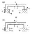
本発明の試料調整用溶媒の第1の使用方法について、概念的に、図1(A)及び(B)に示す1本のキャピラリーカラムを用いたキャピラリー電気泳動装置を例に説明する。まず図1(A)において、泳動媒体1が充填されたキャピラリーカラム2の一端を、分析試料が本発明の試料調製用溶媒によって調整された試料溶液3中に浸し、キャピラリーカラム2の他端部を泳動バッファ4中に浸す。その後、電気泳動用高圧電源5により電極6,7を介して、試料溶液3と泳動バッファ液4間に所定の電圧を印加し、試料溶液3中の試料を電気泳動的にキャピラリーカラム2の一端に移動させることでキャピラリーカラム2への試料の注入を行う。キャピラリーカラム2の一端に試料が注入された後、電圧印加をいったん止め、キャピラリーカラム2の試料注入側の端部を、図(B)に示す泳動バッファ8に移動し、浸す。その後、泳動バッファ4、8間に、高電圧を印加して試料成分の電気泳動を行い、キャピラリーカラムの他端側に設けられた図示しない光学的測定部により、測定光や励起光を照射して吸光度や蛍光を測定して試料の検出を行う。The first method of using the sample preparation solvent of the present invention will be conceptually described by taking a capillary electrophoresis apparatus using one capillary column shown in FIGS. 1A and 1B as an example. First, in FIG. 1 (A), one end of a
図2に、キャピラリー電気泳動装置における、本発明の試料調製用溶媒の第2の使用方法を示す。図2は、図1におけるキャピラリーカラム2の試料注入側の端部を拡大した図である。試料溶液を収容するウェル10中で、本発明の試料調製用溶媒で試料を調製した試料溶液3を下層に、水又は水に近い比重をもつ溶液21を上層に重層する。キャピラリーカラム2へ試料注入の際には、キャピラリーカラム2の試料注入側の先端をウェル10中の下層の試料溶液3中に浸す。その後、試料注入用の電圧を、電気泳動用高圧電源より電極6、7を介して試料溶液3と泳動バッファ4間に印加し、キャピラリーカラムへの試料の注入を行う。以降の電気泳動は、図1と同様に行う。
以上、キャピラリーカラムへの試料の注入は、電気的導入法により説明したが、試料注入法はこれに限定されず、吸引法、加圧法など密閉されていない容器に微量の試料溶液が収容されている場合においても、本発明の試料調製用溶媒を使用することで試料溶液の乾燥を防ぐことが可能である。
キャピラリーチューブの内径は、10nm〜1000μmで、好ましくは、50〜100μmである。試料溶液を収容するウェルは、収容可能な溶液が数10nL〜数μLとなるように設定するのが好ましい。FIG. 2 shows a second method of using the sample preparation solvent of the present invention in a capillary electrophoresis apparatus. FIG. 2 is an enlarged view of the end portion on the sample injection side of the
As described above, the sample injection into the capillary column has been described by the electrical introduction method, but the sample injection method is not limited to this, and a small amount of the sample solution is accommodated in an unsealed container such as a suction method or a pressure method. Even in this case, it is possible to prevent drying of the sample solution by using the sample preparation solvent of the present invention.
The inner diameter of the capillary tube is 10 nm to 1000 μm, preferably 50 to 100 μm. The well for storing the sample solution is preferably set so that the solution that can be stored is several tens of nL to several μL.
また、図1、図2の使用例においても、試料溶液3を収容するウェル10は、96、386ウェルを有するマイクロタイタープレート等を使用して、一度に複数の試料を収容することができる。さらには、複数枚の当該マイクロタイタープレートを装置内で保管する場合もあり、その場合には試料容器に収容された試料溶液は、試料によってはキャピラリーカラムに注入されるまでに長時間の待機を要する。この間、試料溶液から溶媒が蒸散し試料の濃縮が起こる可能性があるが、本発明の試料調製用溶媒を用いて試料を調製することによって、試料溶液の乾燥を防ぎ分析精度の向上が可能である。また、多数の試料溶液を分析装置に待機させることが可能となり、人手による分析装置への試料装填の回数を減らすことで、作業効率の向上を図ることができる。Also in the usage examples of FIGS. 1 and 2, the well 10 for storing the
次に、本発明の試料調製用溶媒を使用する、その他のキャピラリー流路を備えた分析装置として、MEMSキャピラリープレートを電気泳動部材として用いた装置における使用方法を図3を参照して説明する。
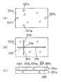
泳動部材は一対の板状部材331a、331bからなる。図3(A)は板状部材331aの上面図、(B)は331bの上面図、(C)は泳動部材の断面図である。一方の基材331bの表面には半導体製造プロセスに用いられる写真製版技術、又は、マイクロマシニング技術等により、互いに交差する泳動用キャピラリー流路333、335が形成され、他方の基材331aには、その流路333、335の端に対応する位置に貫通穴がアノードリザーバ337a、カソードリザーバ337c、サンプルリザーバ337s、サンプルウエストリザーバ337wとして設けられている。試料の注入に先立って、例えば、シリンジを使った圧送により、いずれかのリザーバからキャピラリー流路333,335に泳動媒体を充填する。ついで、リザーバ内に充填された泳動媒体を除去し、短い方のキャピラリー流路333(サンプル注入流路)の一方の端に対応するサンプルリザーバ337sに試料溶液を注入し、他のリザーバ337w、337c、337aに泳動バッファ溶液を注入する。その後、各リザーバ337s、337w、337a、337cに所定の電圧を印加して、試料を両キャピラリー流路の交差部339に導く。交差部339がサンプルで満たされた後、各リザーバに印加する電圧を切り換えて長い方のキャピラリー流路335に、交差部339のサンプルを注入する。
キャピラリー流路の幅は、10nm〜1000μm、好ましくは、50μm〜100μmである。各リザーバの容積は、収容可能な溶液が数10nL〜数μLになるように設定することが好ましい。Next, a method of using an MEMS capillary plate as an electrophoretic member as an analysis apparatus using another sample preparation solvent using the sample preparation solvent of the present invention will be described with reference to FIG.
The migration member is composed of a pair of plate-
The width of the capillary channel is 10 nm to 1000 μm, preferably 50 μm to 100 μm. The volume of each reservoir is preferably set so that the solution that can be accommodated is several tens of nL to several μL.
キャピラリープレートを電気泳動部材として用いた電気泳動装置における、本発明の試料調製用溶媒の第2の使用方法としては、キャピラリー流路に泳動媒体を充填し、各リザーバに充填された泳動媒体を洗浄後、サンプルリザーバ337sに予め水を投入しておき、その後、本発明の試料調製用溶媒で試料を調整した試料溶液をサンプルリザーバの底部に投入し、試料溶液を下層に、水を上層に重層させてもよい。 In the electrophoresis apparatus using the capillary plate as an electrophoresis member, the second method of using the sample preparation solvent of the present invention is to fill the capillary channel with the electrophoresis medium and wash the electrophoresis medium filled in each reservoir. After that, water is added to the
次に本発明の試料調製用溶媒について説明を行う。
分析試料を調製するための本発明の試料調整用溶媒は、水を基本として構成され、エチレングリコールを含む。
多価アルコールは、水と容易に混和し、水に対して高い比重を持つ。また、多価アルコールの沸点は、エチレングリコールの沸点が198℃、グリセリンの沸点が290℃等と高く、また昇華性も低いため、水分の蒸散を抑え、試料液の乾燥を防止することができる。従来から、ホルムアミドが、古典的なスラブゲル電気泳動と同様、マイクロキャピラリーチューブあるいはキャピラリープレートを用いた電気泳動のための試料調製用溶媒に添加されているが、多価アルコールと比較して反応性が高く、化学的には不安定である。また、ホルムアミドの蒸気を吸引することによる肝機能障害の報告もある等、生体や環境に対する影響が大きい。一方、多価アルコールはタンパク質や核酸等生体分子の試料成分に対する影響も少なく、試料の保存性においても優れた特性を持つほか、分解産物を生じにくく、分析試料の泳動分離に影響を与えにくい。更に、環境への影響についても生分解性が良好であるため最小限に止めることができ、生態に対する毒性も低い。
添加成分として多価アルコールのみを添加する場合は、試料調製溶媒中において、好ましくは、5〜80(w/v)%、更に好ましくは20〜60(w/v)%、更に好ましくは35〜55(w/v)%含有する。Next, the sample preparation solvent of the present invention will be described.
The sample preparation solvent of the present invention for preparing an analysis sample is constituted on the basis of water and containsethylene glycol.
Polyhydric alcohols are easily mixed with water and have a high specific gravity relative to water. The boiling point of polyhydric alcohol is such that the boiling point of ethylene glycol is as high as 198 ° C., the boiling point of glycerin is as high as 290 ° C., and the sublimation property is low. . Conventionally, formamide has been added to sample preparation solvents for electrophoresis using microcapillary tubes or capillary plates, as in classic slab gel electrophoresis, but it is more reactive than polyhydric alcohols. High and chemically unstable. In addition, there are reports of liver dysfunction due to inhalation of formamide vapor, which has a great impact on the body and the environment. On the other hand, polyhydric alcohols have little influence on sample components of biomolecules such as proteins and nucleic acids, have excellent characteristics in terms of sample storage stability, do not easily generate degradation products, and do not easily affect migration separation of analysis samples. Furthermore, the environmental impact can be minimized because of its good biodegradability, and the toxicity to the environment is low.
When only the polyhydric alcohol is added as an additive component, it is preferably 5 to 80 (w / v)%, more preferably 20 to 60 (w / v)%, and more preferably 35 to 35% in the sample preparation solvent. Contain 55 (w / v)%.
また、本発明の試料調整用溶媒は、エチレングリコールを含み、好ましくは、1気圧における沸点が、101〜300℃、更に好ましくは120〜250℃であることを特徴とする。
1気圧における沸点を101℃〜300℃とすることで、マイクロリットルオーダーの試料溶液を試料容器に投入し、高温環境下に放置、あるいは、長時間放置におかれる場合であっても試料溶液の濃縮を防ぐことができる。
The sample preparation solvent of the present invention containsethylene glycol , and preferably has a boiling point of 101 to 300 ° C., more preferably 120 to 250 ° C. at 1 atmosphere.
By setting the boiling point at 1 atm to 101 ° C. to 300 ° C., a sample solution of microliter order is put into a sample container and left in a high temperature environment or left for a long time. Concentration can be prevented.
以下に実施例を示し、本発明を具体的に説明するが、本発明は下記の実施例に制限されるものではない。
[実施例1]EXAMPLES Hereinafter, the present invention will be specifically described with reference to examples. However, the present invention is not limited to the following examples.
[Example 1]
本実施例においては、DNA試料を本発明の試料調整用溶媒を用いて調製し、キャピラリープレートを構成要素に持つ電気泳動装置においてサンガー反応を利用した電気泳動分析を行った。 In this example, a DNA sample was prepared using the sample preparation solvent of the present invention, and electrophoretic analysis using a Sanger reaction was performed in an electrophoresis apparatus having a capillary plate as a component.
図4に、本実施例で使用した電気泳動部材を示す。図4において、(A)はキャピラリープレートからなる電気泳動部材におけるキャピラリー流路の平面図、(B)はカソード端におけるサンプルリザーバ部分の拡大平面図、(C)はカソード端部の斜視図、(D)はカソード端の断面図を示す。FIG. 4 shows the electrophoretic member used in this example. 4, (A) is a plan view of a capillary channel in an electrophoretic member comprising a capillary plate, (B) is an enlarged plan view of a sample reservoir portion at the cathode end, (C) is a perspective view of the cathode end, D) shows a sectional view of the cathode end.
電気泳動部材は一対の板材410a、410bが接合されたものである。一方の板材410aには、キャピラリー流路からなる分離流路412が複数本、例えば384本形成されており、互いに交差しないように配列されている。
各分離流路412の一端は、基板表面に開口したそれぞれのサンプルリザーバ(以下、小容量リザーバ、という)に接続され、基板表面には全ての小容量リザーバ414aを含む大きさの大容量リザーバ416aが壁48で囲まれて形成されている。各分離流路412の他端(アノード端)は基板表面に形成された共通のリザーバ416bに接続されるように開口している。The electrophoretic member is formed by joining a pair of
One end of each
分離流路の幅は10nm〜1000μmであり、好ましくは50〜130μmであり、深さは10nm〜1000μm、好ましくは20μm〜60μmである。他方の板材410bには、分離流路412の両端に対する位置に貫通穴が形成されている。一端側の貫通穴は小容量リザーバ414aであり、小容量リザーバ414aのサイズは直径が10μm〜3mm、好ましくは50μm〜2mmであり、数10nL〜数μLの試料を注入するのに適した大きさに設定されている。両板材410aと410bは、分離流路412が内側になるように張り合わされて、一体の基材となっている。 The width of the separation channel is 10 nm to 1000 μm, preferably 50 to 130 μm, and the depth is 10 nm to 1000 μm, preferably 20 μm to 60 μm. On the
板材410aへの分離流412の形成はリソグラフィーとエッチング(ウェットエッチング又はドライウェッティング)により形成することができる。板材410bへの貫通穴の形成はサンドブラストやレーザードリルなどの方法により形成することができる。 The
小容量リザーバ414aは大容量リザーバ416aによって領域全体を覆われており、その斜視図を示す(C)のように全ての小容量リザーバ414aは大容量リザーバ416a内に設けられ、リザーバ416aとつながっている。他端側のリザーバ416bも全ての分離流路412の他端側の開口が配置されている領域を覆っており、全ての分離流路412の他端側の開口はリザーバ416bとつながっている。
基板を構成する板材410a、410bの材質としては、石英ガラスやホウ酸系ガラス、樹脂などを用いることができ、泳動分離された成分を光学的に検出する場合には透明な材質を選択する。光以外の検出手段を使用する場合は、板材410a、410bの材質は透明なものに限定されるものではない。The small-
Quartz glass, boric acid glass, resin, or the like can be used as the material of the
小容量リザーバ414aの内壁を親水性、大容量リザーバ416aの底面又は底面から内壁面にかけて疎水性としてもよい。 The inner wall of the small-
そのような親水性と疎水性の表面処理としては、種々の方法を挙げることができる。例えば、板材としてガラス板を使用した場合には、酸で処理することにより親水性を持たせることができ、樹脂コーティング、フッ素樹脂加工、シランカップリング剤処理などにより疎水性を持たせることができる。 Examples of such hydrophilic and hydrophobic surface treatments include various methods. For example, when a glass plate is used as the plate material, it can be made hydrophilic by treatment with acid, and can be made hydrophobic by resin coating, fluororesin processing, silane coupling agent treatment, etc. .
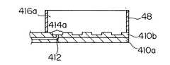
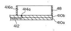
図5に他のキャピラリープレートにおけるカソード側の断面図を示す。小容量リザーバ414aは板材410bの表面側に凹部として形成され、その底部で分離流路412とつながっている。複数の小容量リザーバ414aが大容量416bに覆われて、大容量リザーバ416bの底面上に形成されている。
図6は更に他のキャピラリープレートにおけるカソード側の断面図を示す。小容量リザーバ414aは分離流路412と同程度の大きさの開口として形成されている。FIG. 5 shows a sectional view of the cathode side of another capillary plate. The small-
FIG. 6 shows a cross-sectional view of the cathode side of still another capillary plate. The small-
これら図5又は図6に示されるキャピラリープレートにおいても、小容量リザーバ414aと、大容量リザーバ416aの底面のうち小容量リザーバ414aの開口部の狭い範囲の周辺部が親水性、その外側が疎水性となるように表面処理を施してもよい。これにより、注入された試料溶液は親水性処理が施された部分に保持されることになり、その親水性領域が小容量リザーバとなる。その親水性領域の大記載は、保持される試料量が数10nL〜数μLとなるのに適した大きさに設定される。 Also in the capillary plate shown in FIG. 5 or FIG. 6, the
次に、図4に示したキャピラリープレートにおける試料注入動作を図7を参照して説明する。
(1) キャピラリープレートを50℃の恒温状態に保つ。
(2) カソード側の大容量リザーバ416aに純水、例えばMilli−Q水を満たし、アノード側からシリンジで加圧して全ての分離流路412に泳動媒体を充填する。
(3) 分離流路412から小容量リザーバ414aに流出した泳動媒体は、大容量リザーバ416aの純水中に拡散するので、リザーバ414a、416a内の水及び泳動媒体を吸引ノズルによって吸引し、リザーバ414a、416a内を洗浄する。Next, the sample injection operation in the capillary plate shown in FIG. 4 will be described with reference to FIG.
(1) Keep the capillary plate at a constant temperature of 50 ° C.
(2) The large-
(3) Since the electrophoresis medium that has flowed out of the
(4) リザーバ414a、416a内を洗浄後、カソード側リザーバ416aとアノード側リザーバ416bに泳動バッファ溶液を満たし、両リザーバ414a、416b間に電圧を印加してプレセパレーションを行い、ゲル中の夾雑物イオンをアノード電極又はカソード電極に移動させる。印加電圧は、例えば125V/cmで、印加時間は5分間である。
(5) カソード側リザーバ416aの泳動バッファ溶液を吸引し、リザーバ416a内を洗浄した後、リザーバ416a内を純水、例えばMilli−Q水で満たす。
(6) その後、純水で満たされたリザーバの各小容量リザーバ414aに順次又は複数個を単位としてピペッタ46によって試料溶液49を滴下する。試料溶液滴下は、ピペッタ46の先端を小容量リザーバ414aの近くまで、例えば上部から約0.5mm離れた位置まで降下させて行う。このときも、キャピラリープレートは50℃の恒温状態が維持されている。(4) After washing the
(5) The electrophoresis buffer solution in the
(6) Thereafter, the
(7) 各小容量リザーバ414aにカソード電極を挿入し、アノード電極との間に泳動電圧を印加して流路412への試料注入を行う。試料注入のための印加電圧は、例えば50V/cmで、印加時間は40秒間である。
(8) リザーバ416aの純水とともに小容量414a内に残った試料も吸引して洗浄した後、リザーバ414a、416bを泳動バッファで満たす。(7) A cathode electrode is inserted into each small-
(8) The sample remaining in the
(9) リザーバ414aにカソード電極を挿入し、アノード電極との間に泳動電圧を印加して試料の電気泳動分離と信号検出を行う。泳動分離のための印加電圧は、70〜300V/cmが適当であり、例えば125V/cmである。
電極はリザーバ416a、416bにそれぞれ予め設けておいてもよく、別途挿入するようにしてもよい。また、試料注入側では、リザーバ414aごとに電極を設けておいてもよく、別途挿入するようにしてもよい。(9) A cathode electrode is inserted into the
The electrodes may be provided in advance in the
測定条件は次の通りである。 The measurement conditions are as follows.
DNA試料はサイクルシークエンシング用試薬キットBigDye Terminator Cycle Sequencing Ready Reaction Kit v3.1(アプライドバイオシステムズ社製)により作成した。鋳型DNAはpUC18 プラスミドDNA(東洋紡社製)、プライマーは(キアゲン受託合成品)を使用した。反応容量は2.5μLとした。その他条件はキット取扱説明に従い、エタノール沈殿処理の後、乾燥固化した標品を得た。The DNA sample was prepared by using BigDye Terminator Cycle Sequencing Ready Reaction Kit v3.1 (Applied Biosystems) for cycle sequencing. The template DNA used was pUC18 plasmid DNA (manufactured by Toyobo Co., Ltd.), and the primer (Qiagen Contract Synthetic Product) was used. The reaction volume was 2.5 μL. Other conditions were in accordance with the instruction manual of the kit, and after the ethanol precipitation treatment, a dried and solid sample was obtained.
シークエンサー用試料調製用溶媒としては、次の3種類の溶媒を用意した。
(イ)50%(w/v)エチレングリコール、0.4mM Tris-HCl (pH8.0)及び0.04 mM EDTAの各成分を含む水溶液。
(ロ)60%(w/v)ホルムアミド、0.4mM Tris-HCl (pH8.0)、0.04 mM EDTAの各成分を含む水溶液。
(ハ)精製水(比較用試料調製用溶媒)。As the sample preparation solvent for the sequencer, the following three solvents were prepared.
(I) An aqueous solution containing 50% (w / v) ethylene glycol, 0.4 mM Tris-HCl (pH 8.0) and 0.04 mM EDTA.
(B) An aqueous solution containing 60% (w / v) formamide, 0.4 mM Tris-HCl (pH 8.0), and 0.04 mM EDTA.
(C) Purified water (Comparative sample preparation solvent).
上記DNA試料の乾燥標品を前述の(イ)から(ハ)の3種の試料調製用溶媒5μLを用いて溶解させ、シークエンサーに供する試料溶液を調製した。各試料液2.3μLを、上述のように図4に示すシークエンサーのBioMEMSキャピラリープレート上に形成された小容量リザーバ414aへ機械的に制御されたピペッター46で注入した。 The dried sample of the above DNA sample was dissolved using 5 μL of the three sample preparation solvents (A) to (C) described above to prepare a sample solution to be used for the sequencer. 2.3 μL of each sample solution was injected with a mechanically controlled
図8に泳動結果を示す。各シークエンシングデータはpUC18 plasmid DNAの4種の蛍光シグナルのうち、Gについての蛍光シグナルを示す。図中グラフの縦軸は蛍光強度を示す。また、横軸は検出時間を示し、グラフ左側が分析開始点である。(A)は調製に溶媒(イ)を用いた試料の電気泳動データ、(B)は調製に溶媒(イ)を用いた試料の電気泳動データ、及び(C)は調製に溶媒(ハ)である精製水を用いた試料の電気泳動データである。(A)及び(B)では正常なシークエンシングデータが得られたが、(C)の水で調製されたの試料液ではシグナルが観察されなかった。これはピペッターチップから水中への試料溶液の吐出の際に試料溶液の比重が水とほぼ同じであるため、泳動媒体にDNA試料が移行する前にリザーバ416a内の液中に拡散したためと考えられる。(A)及び(B)は同等の結果が得られたが、エチレングリコールとホルムアミドは水より比重が高く、両者はほぼ同等の比重を持つためである。
[実施例2]FIG. 8 shows the electrophoresis results. Each sequencing data shows the fluorescence signal about G among four types of fluorescence signals of pUC18 plasmid DNA. The vertical axis of the graph in the figure indicates the fluorescence intensity. The horizontal axis indicates the detection time, and the left side of the graph is the analysis start point. (A) Electrophoresis data of sample using solvent (a) for preparation, (B) Electrophoresis data of sample using solvent (a) for preparation, and (C) Solvent (c) for preparation. It is the electrophoresis data of the sample using a certain purified water. In (A) and (B), normal sequencing data was obtained, but no signal was observed in the sample solution prepared with water in (C). This is considered to be because the specific gravity of the sample solution is almost the same as that of water when the sample solution is discharged from the pipettor chip into the water, so that the DNA sample diffuses into the liquid in the
[Example 2]
本実施例においては、本発明の試料調整用溶媒の乾燥に対する耐性に関する比較を行った。 In this example, a comparison was made regarding the resistance to drying of the sample preparation solvent of the present invention.
本実施例で使用した電気泳動部材は実施例1と同様であるが、キャピラリープレートは泳動開始まで室温に保たれている。試料注入動作は、実施例1の(2)から(4)までは同様で(5)以降は次の通りである。
(5)カソード側リザーバ416aのバッファ溶液を吸引し、リザーバ416a内を洗浄した後、リザーバ414aにピペッタ46によって試料溶液49を5μL滴下する。
(6)リザーバ414aの上面を開放したまま24時間放置後、各小容量リザーバ41aにカソード電極を挿入し、アノード電極との間に電圧を印加して流路412への試料注入を行う。試料注入のための印加電圧は、例えば50V/cmで、印加時間は40秒間である。
(7)小容量リザーバ414a内に残った試料を吸引して洗浄した後、リザーバ414a、416a内をバッファ溶液で満たす。
(8)リザーバ416aにカソード電極を挿入し、アノード電極との間に泳動電圧を印加して試料の電気泳動分離と信号検出を行う。The electrophoresis member used in this example is the same as that in Example 1, but the capillary plate is kept at room temperature until the start of electrophoresis. The sample injection operation is the same from (2) to (4) of the first embodiment, and is the following from (5).
(5) The buffer solution in the
(6) After leaving the upper surface of the
(7) After the sample remaining in the
(8) A cathode electrode is inserted into the
DNA試料調製条件とシークエンサー用試料調製用溶媒は実施例1と同じ条件で調製した。The DNA sample preparation conditions and sequencer sample preparation solvent were prepared under the same conditions as in Example 1.
泳動結果を図9に示す。各シークエンシングデータはpUC18 plasmid DNAの4種の蛍光シグナルのうち、Gについての蛍光シグナルを示す。図中グラフの縦軸は蛍光強度を示す。また、横軸は検出時間を示し、グラフ右側が長鎖側シグナルである。(A)は室温放置前の溶媒(イ)によって調製した試料の電気泳動データである。(B)は24時間室温放置後の溶媒(イ)によって調製した試料の電気泳動データである。(C)は室温放置前の溶媒(ロ)によって調製した試料の電気泳動データである。(D)は24時間室温放置後の溶媒(ロ)によって調製した試料の電気泳動データである。(イ)のエチレングリコールを含む試料調製用溶媒で調製された試料および(ロ)のホルムアミドを含む試料調製用溶媒で調製された試料では蛍光標識された反応産物が検出されたことを示すシグナルが確認できたが、溶媒(ハ)である水で調製されたの試料液マイクロプレートのウェル内で完全に枯渇したため、分析不能となった。一方、試料調製用溶媒(イ)と(ロ)の結果を比較すると、(D)に示す試料調製用溶媒(ロ)のデータにおいて300塩基付近にホルムアミド分解産物と考えられるベースラインの盛り上がりが観察された。この現象は、コンピューターで行うシークエンシングデータの解読において塩基配列の誤読を生じる恐れがある。試料調製用溶媒(イ)によって調製した場合は、試料調製用溶媒(ロ)で調製した場合に比べて、分析に影響を与えることなく、長時間の室温放置に耐え得ることが確認できた。エチレングリコールは多価アルコールの一種であるが化学的性質が類似している、グリセロール、ペンタエリスリトール、プロピレングリコール、マンニトール等の他の多価アルコールも同様の性質を保有するものと考えられる。The result of electrophoresis is shown in FIG. Each sequencing data shows the fluorescence signal about G among four types of fluorescence signals of pUC18 plasmid DNA. The vertical axis of the graph in the figure indicates the fluorescence intensity. The horizontal axis represents the detection time, and the right side of the graph is the long chain signal. (A) is the electrophoresis data of the sample prepared with the solvent (a) before standing at room temperature. (B) is the electrophoresis data of the sample prepared with the solvent (A) after being left at room temperature for 24 hours. (C) is electrophoresis data of a sample prepared with a solvent (b) before standing at room temperature. (D) is electrophoresis data of a sample prepared with a solvent (b) after standing at room temperature for 24 hours. A signal indicating that a fluorescently labeled reaction product was detected in the sample prepared with the sample preparation solvent containing ethylene glycol of (a) and the sample prepared with the sample preparation solvent of (b) formamide. Although it was confirmed, analysis was impossible because the sample solution microplate prepared with water as the solvent (c) was completely depleted in the well. On the other hand, when the results of the solvent for sample preparation (a) and (b) are compared, a rise in the baseline, which is considered to be a formamide degradation product, is observed around 300 bases in the data for the solvent for sample preparation (b) shown in (D) It was done. This phenomenon may cause misreading of base sequences in decoding of sequencing data performed by a computer. When prepared with the sample preparation solvent (ii), it was confirmed that the sample preparation solvent (ii) can withstand prolonged room-temperature standing without affecting the analysis as compared with the case of using the sample preparation solvent (ii). Ethylene glycol is a kind of polyhydric alcohol, but other polyhydric alcohols such as glycerol, pentaerythritol, propylene glycol, mannitol and the like having similar chemical properties are considered to have similar properties.
46 ピペッタ−
48 壁
414a、414b 板材
412 分離流路46 Pipetter
48
Claims (1)
Translated fromJapanesePriority Applications (4)
| Application Number | Priority Date | Filing Date | Title |
|---|---|---|---|
| JP2005086638AJP4645255B2 (en) | 2005-03-24 | 2005-03-24 | Analysis sample preparation solvent |
| US11/386,808US20060213775A1 (en) | 2005-03-24 | 2006-03-23 | Solvent for preparation of analytical sample |
| GB0605916AGB2427028B (en) | 2005-03-24 | 2006-03-24 | A method and solvent for electrophoresis measurements |
| US12/078,820US20080257734A1 (en) | 2005-03-24 | 2008-04-07 | Method for analyzing analytical sample in high-throughput type automatic analytical device |
Applications Claiming Priority (1)
| Application Number | Priority Date | Filing Date | Title |
|---|---|---|---|
| JP2005086638AJP4645255B2 (en) | 2005-03-24 | 2005-03-24 | Analysis sample preparation solvent |
Publications (2)
| Publication Number | Publication Date |
|---|---|
| JP2006266921A JP2006266921A (en) | 2006-10-05 |
| JP4645255B2true JP4645255B2 (en) | 2011-03-09 |
Family
ID=36384098
Family Applications (1)
| Application Number | Title | Priority Date | Filing Date |
|---|---|---|---|
| JP2005086638AExpired - LifetimeJP4645255B2 (en) | 2005-03-24 | 2005-03-24 | Analysis sample preparation solvent |
Country Status (3)
| Country | Link |
|---|---|
| US (2) | US20060213775A1 (en) |
| JP (1) | JP4645255B2 (en) |
| GB (1) | GB2427028B (en) |
Families Citing this family (4)
| Publication number | Priority date | Publication date | Assignee | Title |
|---|---|---|---|---|
| EP1918024B1 (en)* | 2006-09-19 | 2010-10-06 | CSEM Centre Suisse d'Electronique et de Microtechnique SA - Recherche et Développement | Device and method for calibrating a pipette or a dispensing system |
| WO2008136057A1 (en)* | 2007-04-25 | 2008-11-13 | Shimadzu Corporation | Electrophoretic chip and method of electrophoresis |
| US8834694B2 (en)* | 2010-12-27 | 2014-09-16 | Mo Bio Laboratories, Inc. | Dry compositions and methods for gel electrophoresis |
| EP3123161B1 (en)* | 2014-03-28 | 2019-12-18 | GE Healthcare Bio-Sciences AB | Electrophoresis separation method |
Family Cites Families (22)
| Publication number | Priority date | Publication date | Assignee | Title |
|---|---|---|---|---|
| US5089111A (en)* | 1989-01-27 | 1992-02-18 | Bio-Rad Laboratories, Inc. | Electrophoretic sieving in gel-free media with dissolved polymers |
| US5264101A (en)* | 1989-11-06 | 1993-11-23 | Applied Biosystems, Inc. | Capillary electrophoresis molecular weight separation of biomolecules using a polymer-containing solution |
| JPH055723A (en)* | 1990-11-05 | 1993-01-14 | Herena Kenkyusho:Kk | Supplying method of reagent for electrophoresis and thin-layer reagent supplying body |
| JPH05281192A (en)* | 1992-03-31 | 1993-10-29 | Shimadzu Corp | Electrolyte for constant velocity electrophoresis |
| CA2123940A1 (en)* | 1993-06-21 | 1994-12-22 | Philip A. Guadagno | Electrophoresis plate |
| AU3028797A (en)* | 1996-05-24 | 1998-01-05 | Novartis Ag | Process for separating mixtures of substances using capillary affinity gel electrophoresis |
| WO1998058240A1 (en)* | 1997-06-19 | 1998-12-23 | Toyota Jidosha Kabushiki Kaisha | Method of retaining fine liquid droplet, reaction generating method and reaction vessel |
| US6764817B1 (en)* | 1999-04-20 | 2004-07-20 | Target Discovery, Inc. | Methods for conducting metabolic analyses |
| KR100349361B1 (en)* | 1999-05-29 | 2002-08-21 | 주식회사 제일생명공학서비스 | DNA size marker which can be preserved and delivered at room temperature |
| US6465692B1 (en)* | 1999-12-22 | 2002-10-15 | Beckman Coulter, Inc. | Reagents for preparing a sample containing biomolecular analytes for capillary electrophoretic separation and methods for making the reagents |
| US6770698B1 (en)* | 2000-06-05 | 2004-08-03 | The Research Foundation At State University Of New York | Polymer solution for separation of charged macromolecules by electrophoresis |
| JP3852327B2 (en)* | 2001-11-30 | 2006-11-29 | 株式会社島津製作所 | Reservoir member for electrophoresis member and electrophoresis member |
| JP3537802B2 (en)* | 2001-12-18 | 2004-06-14 | 株式会社日立製作所 | Electrophoresis chip |
| US20030224444A1 (en)* | 2002-02-25 | 2003-12-04 | Sabbadini Roger A. | Antibodies to native conformations of membrane proteins |
| AU2003234090A1 (en)* | 2002-04-11 | 2003-10-27 | Medimmune Vaccines, Inc. | Spray freeze dry of compositions for pulmonary administration |
| US6939453B2 (en)* | 2002-08-14 | 2005-09-06 | Large Scale Proteomics Corporation | Electrophoresis process using ionic liquids |
| GB0219248D0 (en)* | 2002-08-17 | 2002-09-25 | Univ York | OPtical assembly and method for detection of light transmission |
| US20070025974A1 (en)* | 2003-02-26 | 2007-02-01 | Hardings Fiona A | Amylases producing an altered immunogenic response and methods of making and using the same |
| JP3745743B2 (en)* | 2003-04-11 | 2006-02-15 | 株式会社住化分析センター | Quantitative determination of impurities on material surface |
| PL1663244T3 (en)* | 2003-09-12 | 2008-01-31 | 4 Aza Ip Nv | Pteridine derivatives for the treatment of tnf-alpha-related diseases. |
| JP4406551B2 (en)* | 2003-10-14 | 2010-01-27 | 富士フイルム株式会社 | Azo dye, coloring composition for image formation, ink for inkjet recording, thermal recording material, color toner and color filter |
| WO2005078016A1 (en)* | 2004-02-05 | 2005-08-25 | Millipore Corporation | Room temperature stable agarose solutions |
- 2005
- 2005-03-24JPJP2005086638Apatent/JP4645255B2/ennot_activeExpired - Lifetime
- 2006
- 2006-03-23USUS11/386,808patent/US20060213775A1/ennot_activeAbandoned
- 2006-03-24GBGB0605916Apatent/GB2427028B/ennot_activeExpired - Fee Related
- 2008
- 2008-04-07USUS12/078,820patent/US20080257734A1/ennot_activeAbandoned
Also Published As
| Publication number | Publication date |
|---|---|
| GB2427028A (en) | 2006-12-13 |
| GB0605916D0 (en) | 2006-05-03 |
| GB2427028B (en) | 2009-12-02 |
| US20080257734A1 (en) | 2008-10-23 |
| US20060213775A1 (en) | 2006-09-28 |
| JP2006266921A (en) | 2006-10-05 |
Similar Documents
| Publication | Publication Date | Title |
|---|---|---|
| ES2323408T3 (en) | APPLIANCE AND PROCEDURE FOR FILLING AND CLEANING CHANNELS AND MICROCHIPS INPUT HOLES USED FOR BIOLOGICAL ANALYSIS. | |
| AU755104B2 (en) | Sample handling system for a multi-channel capillary electrophoresis device | |
| JPH11502618A (en) | Capillary electrophoresis apparatus and method | |
| US7850834B2 (en) | Electrophoresis method using capillary plate | |
| JP2002310858A (en) | Sample introduction method in microchip electrophoresis | |
| CN103698382A (en) | Capillary electrophoresis analysis device for trace droplet array and application method thereof | |
| US20030102219A1 (en) | Reservoir member for electrophoretic member and electrophoretic member | |
| JP4645255B2 (en) | Analysis sample preparation solvent | |
| CN106010949B (en) | Sequencing device and method for operating a sequencing device | |
| US7722753B2 (en) | Electrophoresis plate | |
| WO2004038399A1 (en) | Method of controlling migration of substance | |
| Kuldvee et al. | Nonconventional samplers in capillary electrophoresis | |
| KR100762532B1 (en) | Sample analysis method using microchip | |
| JP2002310990A (en) | Electrophoresis device | |
| US20060201809A1 (en) | Sample injection method using capillary plate | |
| JP4692628B2 (en) | Electrophoresis pretreatment method and electrophoresis pretreatment apparatus | |
| JP2000298079A (en) | Molecular transport extraction method | |
| JP4657524B2 (en) | Microchip electrophoresis apparatus and electrophoresis method using the same | |
| JP4608500B2 (en) | Apparatus for receiving fluid sample and method of use thereof | |
| JPH08304339A (en) | Capillary electrophoresis device | |
| JP2013195240A (en) | Capillary assembly | |
| US6994778B2 (en) | Microfluidic device and analyzing method using the same | |
| AU2002318773B2 (en) | Sample Handling System for a Multi-Channel Capillary Electrophoresis device | |
| WO2010100724A1 (en) | Method and apparatus for pretreatment for electrophoresis |
Legal Events
| Date | Code | Title | Description |
|---|---|---|---|
| A621 | Written request for application examination | Free format text:JAPANESE INTERMEDIATE CODE: A621 Effective date:20071220 | |
| A977 | Report on retrieval | Free format text:JAPANESE INTERMEDIATE CODE: A971007 Effective date:20100401 | |
| A131 | Notification of reasons for refusal | Free format text:JAPANESE INTERMEDIATE CODE: A131 Effective date:20100706 | |
| A521 | Request for written amendment filed | Free format text:JAPANESE INTERMEDIATE CODE: A523 Effective date:20100818 | |
| TRDD | Decision of grant or rejection written | ||
| A01 | Written decision to grant a patent or to grant a registration (utility model) | Free format text:JAPANESE INTERMEDIATE CODE: A01 Effective date:20101109 | |
| A01 | Written decision to grant a patent or to grant a registration (utility model) | Free format text:JAPANESE INTERMEDIATE CODE: A01 | |
| A61 | First payment of annual fees (during grant procedure) | Free format text:JAPANESE INTERMEDIATE CODE: A61 Effective date:20101122 | |
| FPAY | Renewal fee payment (event date is renewal date of database) | Free format text:PAYMENT UNTIL: 20131217 Year of fee payment:3 | |
| R151 | Written notification of patent or utility model registration | Ref document number:4645255 Country of ref document:JP Free format text:JAPANESE INTERMEDIATE CODE: R151 | |
| FPAY | Renewal fee payment (event date is renewal date of database) | Free format text:PAYMENT UNTIL: 20131217 Year of fee payment:3 | |
| EXPY | Cancellation because of completion of term |