JP4645159B2 - Micro pump - Google Patents
Micro pumpDownload PDFInfo
- Publication number
- JP4645159B2 JP4645159B2JP2004319256AJP2004319256AJP4645159B2JP 4645159 B2JP4645159 B2JP 4645159B2JP 2004319256 AJP2004319256 AJP 2004319256AJP 2004319256 AJP2004319256 AJP 2004319256AJP 4645159 B2JP4645159 B2JP 4645159B2
- Authority
- JP
- Japan
- Prior art keywords
- flow path
- channel
- volume
- liquid
- micropump
- Prior art date
- Legal status (The legal status is an assumption and is not a legal conclusion. Google has not performed a legal analysis and makes no representation as to the accuracy of the status listed.)
- Expired - Fee Related
Links
Images


Landscapes
- Micromachines (AREA)
- Reciprocating Pumps (AREA)
Description
Translated fromJapaneseこの発明はマイクロポンプに関し、特に、微少量の液体を高精度に送るためのマイクロポンプに関する。 The present invention relates to a micropump, and more particularly to a micropump for feeding a minute amount of liquid with high accuracy.
従来、微少量の液体を搬送するためのマイクロポンプの主な方式としては、逆止弁を用いる機械的な第1の方式と、逆止弁の代わりに液体の流れる方向により流路抵抗が異なるノズルを用いた第2の方式とに大別することができる。第1の方式として、特開平11−257233号公報には、ダイアフラムを稼動させることでポンプ内の液体を加圧し、この圧力を利用して逆止弁を開閉させて液体を搬送するマイクロポンプが記載されている。また、特開平10−299659号公報には、圧力室に連通するノズル部に可動バルブを設け、圧電素子を用いて可動バルブを開閉させて液体の流れの方向性を持たせるマイクロポンプが記載されている。 Conventionally, as a main method of a micropump for transporting a minute amount of liquid, a first mechanical method using a check valve and a flow path resistance differ depending on the direction of liquid flow instead of the check valve. It can be roughly classified into the second method using a nozzle. As a first method, Japanese Patent Laid-Open No. 11-257233 discloses a micropump that pressurizes liquid in a pump by operating a diaphragm and opens and closes a check valve using this pressure to convey the liquid. Are listed. Japanese Patent Application Laid-Open No. 10-299659 describes a micropump in which a movable valve is provided in a nozzle portion communicating with a pressure chamber, and the movable valve is opened and closed using a piezoelectric element so as to have a liquid flow directionality. ing.
第2の方式として、特開平10−110681号公報には、加圧室に連通するノズル部に突起物を設け、流れの方向により流路抵抗が異なるマイクロポンプが記載されている。このマイクロポンプによれば、所望の流れの方向とは逆方向への流れを起こりにくくすることができ、所望の1方向に液体を搬送することができる。 As a second method, Japanese Patent Application Laid-Open No. 10-110682 discloses a micropump in which a protrusion is provided in a nozzle portion communicating with a pressurizing chamber and the flow path resistance is different depending on the flow direction. According to this micropump, it is possible to make it difficult for a flow in the direction opposite to the desired flow direction to occur, and it is possible to transport the liquid in one desired direction.
しかしながら、第1の方式におけるマイクロポンプは、逆止弁または可動バルブを設けるので、構造が複雑で、機械的に劣化しやすいという問題がある。また、特開平10−299659号公報に記載のマイクロポンプは、可動バルブを開閉させるための圧電素子と、圧力室の圧力を変化させるための圧電素子との少なくとも3つの圧電素子が必要である。さらに、これらの圧電素子を別個に駆動するための駆動回路が複雑になってしまうという問題がある。 However, since the micropump in the first system is provided with a check valve or a movable valve, there is a problem that the structure is complicated and mechanical deterioration is likely to occur. Further, the micropump described in Japanese Patent Laid-Open No. 10-299659 requires at least three piezoelectric elements: a piezoelectric element for opening and closing the movable valve and a piezoelectric element for changing the pressure in the pressure chamber. Furthermore, there is a problem that a drive circuit for separately driving these piezoelectric elements becomes complicated.
第2の方式におけるマイクロポンプは、1方向にしか液体を搬送することができないという問題がある。 The micropump in the second method has a problem that it can transport liquid only in one direction.
この発明は上述の問題点を解決するためになされたもので、この発明の目的の1つは、簡単な構成で微少量の液体を正逆両方向に高精度に搬送することが可能なマイクロポンプを提供することである。 The present invention has been made to solve the above-described problems, and one of the objects of the present invention is a micropump capable of conveying a small amount of liquid with high accuracy in both forward and reverse directions with a simple configuration. Is to provide.
上述の目的を達成するためにこの発明のある局面によれば、マイクロポンプは、流路抵抗が差圧に応じて変化する第1流路と、差圧の変化に対する流路抵抗の変化の割合が第1流路よりも小さい第2流路と、第1流路および第2流路に接続された加圧室と、加圧室の内部の圧力を変化させるためのアクチュエータとを備える。 In order to achieve the above object, according to one aspect of the present invention, the micropump includes a first flow path in which the flow path resistance changes according to the differential pressure, and a ratio of the change in the flow path resistance with respect to the change in the differential pressure. Includes a second flow path smaller than the first flow path, a pressurization chamber connected to the first flow path and the second flow path, and an actuator for changing the pressure inside the pressurization chamber.
この発明に従えば、第1流路は流路抵抗が差圧に応じて変化し、第2流路は差圧の変化に対する流路抵抗の変化の割合が第1流路よりも小さいので、差圧が大きいときと小さいときとで第1流路の流路抵抗と第2流路の流路抵抗との比が異なる。アクチュエータにより第1流路および第2流路に接続された加圧室の内部の圧力を変化させるので、第1流路の流路抵抗と第2流路の流路抵抗との比を異ならせることができる。このため、簡単な構成で微少量の液体を正逆両方向に高精度に搬送することが可能なマイクロポンプを提供することができる。 According to this invention, the flow resistance of the first flow path changes according to the differential pressure, and the second flow path has a smaller rate of change in flow resistance with respect to the change in differential pressure than the first flow path. The ratio between the channel resistance of the first channel and the channel resistance of the second channel differs depending on whether the differential pressure is large or small. Since the pressure inside the pressurizing chamber connected to the first flow path and the second flow path is changed by the actuator, the ratio between the flow resistance of the first flow path and the flow resistance of the second flow path is made different. be able to. For this reason, it is possible to provide a micropump that can transport a small amount of liquid in both forward and reverse directions with high accuracy with a simple configuration.
好ましくは、マイクロポンプの第1流路と第2流路それぞれは、一様な断面形状を有し、第1流路の流路長の断面積に対する割合が、第2流路の流路長の断面積に対する割合よりも大きいことを特徴とする。 Preferably, each of the first channel and the second channel of the micropump has a uniform cross-sectional shape, and the ratio of the channel length of the first channel to the sectional area is the channel length of the second channel. It is characterized by being larger than the ratio to the cross-sectional area.
この発明に従えば、第1流路と第2流路それぞれは、一様な断面形状を有し、第1流路の流路長の断面積に対する割合が、第2流路の流路長の断面積に対する割合よりも大きいので、第1流路の差圧の変化に対する流路抵抗の変化の割合が第2流路よりも大きくなる。このため、差圧が大きいときと小さいときとで、第1流路の流路抵抗と第2流路の流路抵抗との比を異ならせることができる。 According to this invention, each of the first channel and the second channel has a uniform cross-sectional shape, and the ratio of the channel length of the first channel to the sectional area is the channel length of the second channel. Therefore, the ratio of the change in the channel resistance to the change in the differential pressure in the first channel is larger than that in the second channel. For this reason, the ratio between the channel resistance of the first channel and the channel resistance of the second channel can be made different depending on whether the differential pressure is large or small.
好ましくは、マイクロポンプの第1流路は、断面積が急激に変化する形状、中心線が直線でない形状、または、流路に障害物を有する形状のいずれかであることを特徴とする。 Preferably, the first flow path of the micropump has any one of a shape in which a cross-sectional area changes rapidly, a shape in which a center line is not a straight line, or a shape having an obstacle in the flow path.
この発明に従えば、第1流路は、断面積が急激に変化する形状、中心線が直線でない形状、または、流路に障害物を有する形状のいずれかなので、第1流路の差圧の変化に対する流路抵抗の変化の割合を第2流路よりも大きくすることができる。 According to the present invention, the first flow path is either a shape whose cross-sectional area changes abruptly, a shape whose center line is not a straight line, or a shape having an obstacle in the flow path. The ratio of the change in flow path resistance to the change in the flow rate can be made larger than that in the second flow path.
好ましくは、マイクロポンプは、加圧室の体積を第1の体積と第2の体積との間で所定の間隔で繰返して変化させるためにアクチュエータを駆動する駆動手段をさらに備え、繰返しは、加圧室の体積を増加させる時間と減少させる時間とが相反することを特徴とする。 Preferably, the micropump further includes driving means for driving the actuator to repeatedly change the volume of the pressurizing chamber between the first volume and the second volume at a predetermined interval. The time for increasing the volume of the pressure chamber and the time for decreasing the pressure chamber are contradictory.
この発明に従えば、駆動手段により加圧室の体積を第1の体積と第2の体積との間で所定の間隔で繰返して変化させるためにアクチュエータが駆動される。その繰返しにおいて加圧室の体積を増加させる時間と減少させる時間とが相反するので、体積を増加させるときと減少させるときとで差圧を異ならせることができる。その結果、アクチュエータの構成を簡単にすることができる。 According to this invention, the actuator is driven in order to repeatedly change the volume of the pressurizing chamber between the first volume and the second volume at a predetermined interval by the driving means. Since the time for increasing the volume of the pressurizing chamber and the time for decreasing are contradictory in the repetition, the pressure difference can be made different between when the volume is increased and when the volume is decreased. As a result, the configuration of the actuator can be simplified.
好ましくはマイクロポンプの駆動手段は、加圧室の体積を増加させる時間が相反する第1の繰返しと第2の繰返しで駆動可能であることを特徴とする。 Preferably, the driving means of the micropump can be driven by the first and second repetitions in which the time for increasing the volume of the pressurizing chamber is contradictory.
この発明に従えば、第1の繰返しと第2の繰返しとで、加圧室の体積を増加させる時間が相反するので、第1の繰返しと第2の繰返しとで液体を搬送する方向を異ならせることができる。 According to the present invention, since the time for increasing the volume of the pressurizing chamber is contradictory between the first repetition and the second repetition, the liquid transport direction is different between the first repetition and the second repetition. Can be made.
好ましくはマイクロポンプは、加圧室の体積を第1の体積と第2の体積との間で所定の間隔で繰返して変化させるためにアクチュエータを駆動する駆動手段をさらに備え、第1流路は、第1の方向の流路抵抗が第1の方向とは逆の第2の方向の流路抵抗よりも大きく、駆動手段は、体積を増加させる時間と減少させる時間とが同じ第1の繰り返しと増加させる時間と減少させる時間とが異なる第2の繰り返しで駆動可能であることを特徴とする。 Preferably, the micropump further includes driving means for driving the actuator to repeatedly change the volume of the pressurizing chamber between the first volume and the second volume at a predetermined interval, and the first flow path includes The flow resistance in the first direction is larger than the flow resistance in the second direction opposite to the first direction, and the driving means performs the first repetition in which the time for increasing the volume and the time for decreasing the volume are the same. It is possible to drive in the second repetition in which the time to increase and the time to decrease are different.
この発明に従えば、駆動手段により加圧室の体積を第1の体積と第2の体積との間で所定の間隔で繰返して変化させるためにアクチュエータが駆動される。第1流路は、第1の方向の流路抵抗が第1の方向とは逆の第2の方向の流路抵抗よりも大きいので、体積を増加させる時間と減少させる時間とが同じ第1の繰返しでは、第2の方向で液体が搬送され、体積を増加させる時間と減少させる時間とが異なる第2の繰返しでは、第1の方向で液体が搬送される。このため、液体を正逆両方向により効率的に搬送することができる。 According to this invention, the actuator is driven in order to repeatedly change the volume of the pressurizing chamber between the first volume and the second volume at a predetermined interval by the driving means. In the first flow path, the flow resistance in the first direction is larger than the flow resistance in the second direction opposite to the first direction, so the time for increasing the volume is the same as the time for decreasing the first flow. In the repetition, the liquid is transported in the second direction, and in the second repetition in which the time for increasing the volume and the time for decreasing the volume are different, the liquid is transported in the first direction. For this reason, the liquid can be efficiently conveyed in both forward and reverse directions.
以下、本発明の実施の形態を図面を参照して説明する。なお、図中同一符号は同一または相当する部材を示し、説明は繰返さない。 Hereinafter, embodiments of the present invention will be described with reference to the drawings. In the drawings, the same reference numerals indicate the same or corresponding members, and description thereof will not be repeated.
図1は、本発明の実施の形態の1つにおけるマイクロポンプの部分的な断面図である。図2は、本発明の実施の形態の1つにおけるマイクロポンプの部分的な平面図である。図1および図2を参照して、マイクロポンプ100は、第1液室111、第1流路115、加圧室109、第2流路117、および第2液室113とが形成された基板101と、基板101上に積層された上側基板103と、上側基板103上に積層された振動板105と、振動板105の加圧室109と対向する側に積層された圧電素子107と、圧電素子107を駆動するための駆動部120とを含む。 FIG. 1 is a partial cross-sectional view of a micropump according to one embodiment of the present invention. FIG. 2 is a partial plan view of a micropump according to one embodiment of the present invention. 1 and 2, the
基板101は、厚さ500[μm]の感光性ガラス基板であり、深さ100[μm]に達するまでエッチングを行なうことにより、第1液室111、第1流路115、加圧室109、第2流路117および第2液室113が形成される。本実施の形態においては、第1流路115はその幅を25[μm]、長さを20[μm]としている。また、第2流路117は、その幅を25[μm]、長さを150[μm]としている。したがって、第1流路115と第2流路117とは、幅および深さが同じで、長さが第1流路よりも第2流路の方が長くなっている。 The
なお、第1流路115および第2流路117は、基板101をエッチング溝加工することによりスリット形状に形成されるものに限られるわけではなく、板材に対してドリル、プレス、レーザ加工等により穴あけ加工をして形成するようにしてもよい。 The
上側基板103は、ガラス基板であり、基板101上に積層されることにより、第1液室111、第1流路115、第2液室113および第2流路117の上面が形成される。上側基板103の加圧室109の上面に当たる部分は、エッチングなどにより加工されて、貫通している。 The
振動板105は、厚さ50[μm]の薄板ガラスである。圧電素子107は、圧電性セラミックスであり、本実施の形態においては厚さ50[μm]のチタン酸ジルコン酸鉛(PZT)セラミックスを用いた。圧電素子107と振動板105とは接着剤等で貼り合わせられている。 The
駆動部120は、圧電素子107に駆動電圧を印加するために、所定の波形の電圧を発生させる。圧電素子107に駆動部120から駆動電圧が印加されることにより、振動板105と圧電素子107とがユニモルフモードの屈曲変形(反り変形)をする。これにより、加圧室109の容積が増減する。 The
本実施の形態におけるマイクロポンプ100では、圧電素子107に30[V]の電圧が印加されると、圧電素子107の変形は、変位量が80[nm]、発生圧力が0.4[MPa]である。 In the
図3は、本実施の形態におけるマイクロポンプの第1流路および第2流路それぞれの差圧と流路抵抗との関係を示す図である。図3(A)は第1流路の場合を示し、図3(B)は第2流路の場合を示す。ここで、流路抵抗とは、液体が流路を流れるときの圧力損失の係数に相当し、単位時間に流れる流体体積を流量Q、液体が流路を流れることによる圧力損失をΔPとしたとき、流路抵抗R[N・s/m5]は、R=ΔP/Qで求められる。ただし、Nは力(Newton)、sは時間(second)である。図3に示した値は、液体に水を用いて、第1流路および第2流路について所定の圧力で液体を流し、そのときの流速から流路抵抗の圧力依存を求めることにより、測定した値である。 FIG. 3 is a diagram showing the relationship between the differential pressure and the channel resistance of each of the first channel and the second channel of the micropump in the present embodiment. FIG. 3A shows the case of the first flow path, and FIG. 3B shows the case of the second flow path. Here, the flow path resistance corresponds to the coefficient of pressure loss when the liquid flows through the flow path. When the volume of fluid flowing per unit time is the flow rate Q and the pressure loss due to the liquid flowing through the flow path is ΔP. The channel resistance R [N · s / m 5] is obtained by R = ΔP / Q. However, N is force (Newton) and s is time (second). The values shown in FIG. 3 are measured by using water as the liquid, flowing the liquid at a predetermined pressure for the first flow path and the second flow path, and determining the pressure dependence of the flow path resistance from the flow velocity at that time. It is the value.
図3を参照して、第1流路115は、流路抵抗の圧力依存が大きいのに対し、第2流路117は流路抵抗の圧力依存が小さいことがわかる。この流路抵抗の圧力依存の違いにより次のことが導き出される。すなわち、差圧が大きいときには、換言すれば加圧室の容積の変化率の絶対値が大きいときには、第1流路は第2流路に比べて液体を通しにくくなり、差圧が小さいとき、換言すれば加圧室109の容積変化率の絶対値が小さいときには、第1流路は第2流路に比べて液体が流れやすい。したがって、加圧室109の容積変化率の絶対値が大きなときには加圧室109の容積変化分の液体は主に第1流路115を通り、また、加圧室の容積変化率が小さなときには加圧室109の容積変化分の液体は主に第2流路117を通ることになる。 Referring to FIG. 3, it can be seen that the
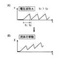
次に、圧電素子107に印加される電圧の波形について説明する。圧電素子107に印加される電圧は、駆動部120で発生される。本実施の形態におけるマイクロポンプ100では、加圧室109の加圧時と減圧時とで圧力の絶対値に差が生じることが必要となる。図4は、圧電素子107に印加する第1の電圧波形と流体の挙動を示す図である。図4(A)は、圧電素子107に印加する第1の電圧波形を示す。図4(A)を参照して、圧電素子107に印加される電圧波形は、立上がりの期間t1が、立下がりの期間t2よりも長い。圧電素子107に印加される電圧が上昇すると、圧電素子107と振動板105は、加圧室109側に反り変形し、その結果、加圧室109の容積が減少する。逆に、圧電素子107に印加される電圧が減少すると、圧電素子の反り変形する変位量が減少するため、加圧室109の容積が増加する。したがって、図4(A)に示す波形の電圧が圧電素子107に印加されると、加圧室109の容積変化率の絶対値は、期間t1の方が期間t2よりも小さくなる。このため、第1流路115は、期間t1の方が期間t2よりも液体を流れやすくし、第2流路117は期間t1と期間t2とで液体の流れやすさはほとんど変わらない。 Next, the waveform of the voltage applied to the
図4(B)は図4(A)に示す波形の電圧が圧電素子107に印加された場合における流体の挙動を示す図である。横軸に時間を、縦軸に流体の位置を示している。流体の位置は、図1の右側を正方向として示している。図4(B)を参照して、液体はマクロには正方向、換言すれば図1の左側から右側に向かう方向に流れる。 FIG. 4B is a diagram illustrating the behavior of the fluid when the voltage having the waveform illustrated in FIG. 4A is applied to the
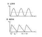
図5は、圧電素子107に印加する第2の電圧波形と流体の挙動を示す図である。図5(A)は、圧電素子107に印加する第2の電圧波形を示す。図5(A)を参照して、圧電素子107に印加される電圧波形は、立上がりの期間t1が、立下がりの期間t2よりも短い。したがって、図5(A)に示す波形の電圧が圧電素子107に印加されると、加圧室109の容積変化率の絶対値は、期間t1の方が期間t2よりも大きくなる。このため、第1流路115は、期間t1の方が期間t2よりも液体を流れにくくし、第2流路117は期間t1と期間t2とで液体の流れやすさはほとんど変わらない。 FIG. 5 is a diagram illustrating the second voltage waveform applied to the
図5(B)は図5(A)に示す波形の電圧が圧電素子107に印加された場合における流体の挙動を示す図である。横軸に時間を、縦軸に流体の位置を示している。流体の位置は、図1の右側を正方向として示している。図5(B)を参照して、液体はマクロには負方向、換言すれば図1の右側から左側に向かう方向に流れる。 FIG. 5B is a diagram illustrating the behavior of the fluid when the voltage having the waveform illustrated in FIG. 5A is applied to the
液体のマクロな流れは、液送り量の効率で表わすことができる。液送り量の効率は、差圧が高圧時における第1流路115の流路抵抗と第2流路117の流路抵抗との比と、差圧が低圧時における第1流路115の流路抵抗と第2流路117の流路抵抗の比とによって定まる。差圧が低圧時における第2流路117に対する第1流路115の流路抵抗比をKlとし、高圧時における第2流路117に対する第1流路115の流路抵抗比をKhとすると、液送り量の効率αは次式(1)で表わされる。 The macro flow of the liquid can be expressed by the efficiency of the liquid feed amount. The efficiency of the liquid feed amount is the ratio between the flow resistance of the
α=(1/(1+Kl))−(1/(1+Kh)) … (式1)
本実施の形態におけるマイクロポンプ100では、低圧時の差圧を10[kPa]とし、高圧時の差圧を100[kPa]である。このとき、低圧時の流路抵抗比Kl≒0.56、高圧時の流路抵抗比Kh≒1.17となる。(1)式を用いて、液送り量効率αは、正方向および負方向ともに約18%となる。α = (1 / (1 + Kl)) − (1 / (1 + Kh)) (Formula 1)
In
(1)式からわかるように、液送り量効率αを向上させるためには、Klができる限り小さく、Khができる限り大きくなることが望ましい。このためには、一方の流路は差圧による流路抵抗の変化ができる限り小さい方がよく(層流的挙動)、他方の流路は圧力による流路抵抗の変化ができる限り大きい方がよい(乱流的挙動)。さらに、低圧時と高圧時とで第1流路および第2流路の流路抵抗の値が逆転するのが好ましい。 As can be seen from the equation (1), in order to improve the liquid feed efficiency α, it is desirable that Kl is as small as possible and Kh is as large as possible. For this purpose, it is better that one channel has a change in flow resistance due to a differential pressure as small as possible (laminar behavior), and the other flow channel has a change in flow resistance caused by pressure as large as possible. Good (turbulent behavior). Furthermore, it is preferable that the flow resistance values of the first flow path and the second flow path are reversed between low pressure and high pressure.
さらに、変化させる差圧の領域を、全体的に高圧方向にシフトする方が液送り量効率を高めるためには好ましい。具体的には、低圧時の圧力を1[kPa]、高圧時の圧力を10[kPa]とするよりも、低圧時の圧力を10[kPa]、高圧時の圧力を100[kPa]とする方がよい。 Further, it is preferable to shift the region of the differential pressure to be changed as a whole in the high pressure direction in order to increase the liquid feed efficiency. Specifically, the pressure at low pressure is set to 10 [kPa] and the pressure at high pressure is set to 100 [kPa] rather than 1 [kPa] at low pressure and 10 [kPa] at high pressure. Better.
[駆動電圧の変形例]
圧電素子107に印加される電圧の立上がりに要する時間と、電圧の立下がりに要する時間とを異ならせるために、最も典型的には、図4(A)または図5(A)に示した波形を用いることができる。ただし、時間軸に対して立上がりと立下がりとが対称でない波形であれば、これに限られるものではない。[Modification of drive voltage]
In order to make the time required for the rise of the voltage applied to the
図6は、本実施の形態におけるマイクロポンプ100の駆動部120が圧電素子107に印加する電圧の波形の変形例を示す図である。図6を参照して、図6(A)は、液体を正方向に搬送する場合の波形を示し、図6(B)は液体を負方向に搬送する場合の波形を示す。図6を参照して、期間t1と期間t2との間に、電圧が変化しない期間t3が含まれる。液体を正方向に搬送する場合には、期間t1が期間t2よりも長くなり、液体を負方向に搬送する場合には、期間t1が期間t2よりも短くなる。期間t1と期間t2との間に電圧が変化しない期間t3が加わった以外については、図4(A)および図5(A)に示した電圧の波形と同じである。期間t3では、電圧が変化しないから、加圧室109の容積に変化はなく、第1流路115と第2流路117の差圧はそれぞれほぼゼロになる。図6に示した波形の電圧を圧電素子107に印加することにより、液体を正方向と負方向とに搬送することができる。 FIG. 6 is a diagram illustrating a modification of the waveform of the voltage applied to the
次に、第1流路115と第2流路117の形状について説明する。第2流路117は、層流で境界層の発達した流れを生じさせる形状である必要がある。このため、レイノルズ数Reが低く、かつ、流路幅に対する流路長の比が大きい方が望ましい。ここで、レイノルズ数Reは、流体力学では一般的な指標となる値である。レイノルズ数が大きいほど乱流域に近づく値を示すものである。流体の密度をρ、粘度をη、流速をv、流路の断面を正方形とした場合に一辺の長さをdとすると、Re=ρvd/ηで求められる。 Next, the shapes of the
レイノルズ数は、流路の断面形状により異なるが、流路が円環状の場合の理論は一般的に知られており、たとえば「水力学」(森北出版)pp.95−96に記されている。それによると、直径をd、長さをLとする円環では、流れが層流(Re<2320)の場合、L>k×Re×dが望まれる。ここで、定数kは、ニクラゼ(Nikuradse)の実験によると、k=0.065、ラングハール(Langharr)の理論によるとk=0.058である。 Although the Reynolds number varies depending on the cross-sectional shape of the flow path, the theory in the case where the flow path is annular is generally known. 95-96. According to this, in an annulus having a diameter d and a length L, when the flow is a laminar flow (Re <2320), L> k × Re × d is desired. Here, the constant k is k = 0.065 according to Nikuradse's experiment and k = 0.058 according to Langharr's theory.
基本的には、流れの方向に垂直な断面形状が一定で、長さの長い流路が好ましいが、境界層の発達した流れを起こすものであれば、これに限られるものではない。また、多少境界層の発達が不十分であっても、第1流路115と比較してより境界層の発達度合いが高い層流であればよい。 Basically, a long channel having a constant cross-sectional shape perpendicular to the flow direction is preferable, but the flow path is not limited to this as long as it causes a flow in which the boundary layer is developed. Even if the boundary layer is somewhat insufficiently developed, it may be a laminar flow having a higher degree of boundary layer development than the
一方、第1流路115は、乱流あるいは渦が発生しやすい形状、もしくは境界層の形成が不十分な領域を含む形状である必要がある。第1流路115は、差圧が大きくなるほど、流路抵抗Rの値が増加する形状であり、以下にこの形状の例を示す。なお、差圧とは、流路の両端における圧力の差をいう。 On the other hand, the
第1流路115の形状の条件は、以下のとおりである。 The conditions of the shape of the
(1) レイノルズ数Reが高い
形状により最適な値は異なるが、円環状の場合は、少なくとも流速のピーク時にRe>2320となる(乱流になる)形状。(1) Reynolds number Re is high The optimum value varies depending on the shape, but in the case of an annular shape, Re> 2320 at least at the peak of the flow velocity (becomes turbulent flow).
(2) 流路の幅dに対して流路長さLの比が比較的小さい形状
形状によりその適切な値は異なるが、円環状の場合、少なくとも流速のピーク時にL<0.065×Re×dとなる形状。(2) A shape in which the ratio of the channel length L to the channel width d is relatively small. The appropriate value varies depending on the shape, but in the case of an annular shape, L <0.065 × Re at least at the peak of flow velocity Xd shape.
図7は、第1流路115の形状の第1の具体例を示す図である。図7を参照して、第1流路115の断面形状を正方形とした場合の一辺の長さをdとし、第1流路115の長さをLとした場合に、L/dが比較的小さいことが条件となる。第1流路115の断面形状を円とした場合には、直径dと流路長さLの比が小さくなることが条件となる。特に、流速のピーク時にL/d<0.065×Reとなることが条件となる。 FIG. 7 is a diagram illustrating a first specific example of the shape of the
図8は、第1流路の形状の第2の具体例を示す図である。図8を参照して、第1流路115Aの幅は、加圧室109側から第1液室111に向かって徐々に大きくなる形状となっている。このような場合においても、第1流路115Aの形状は、上記(2)の条件を満たす形状とすることができる。 FIG. 8 is a diagram illustrating a second specific example of the shape of the first flow path. With reference to FIG. 8, the width of the
図9は、第1流路の形状の第3の具体例を示す図である。図9を参照して、第1流路115Bは、断面積が2段階に変化し、面積の変化が急激な形状となっている。第1流路115Bの断面形状は、円であっても矩形であってもよい。 FIG. 9 is a diagram illustrating a third specific example of the shape of the first flow path. Referring to FIG. 9, the
図10は、第1流路の形状の第4の具体例を示す図である。第1流路115Cは、加圧室109と第1液室111との間に設けられ、液体の流れる方向が直線でなく、折れ曲がっている。 FIG. 10 is a diagram illustrating a fourth specific example of the shape of the first flow path. 115C of 1st flow paths are provided between the
図11は、第1流路の形状の第5の具体例を示す図である。第1流路115Dは、そのほぼ中央に障害物131を備えている。障害物131の液体が流れる方向に垂直な断面形状は、加圧室109側から第1液室111に向かって小さくなる形状となっている。 FIG. 11 is a diagram illustrating a fifth specific example of the shape of the first flow path. The
図12は、第1流路の形状の第6の具体例を示す図である。図12を参照して、加圧室109の第1流路115E近傍に障害物131Aが設けられている。 FIG. 12 is a diagram illustrating a sixth specific example of the shape of the first flow path. Referring to FIG. 12, an
図13は、第1流路の形状の第7の具体例を示す図である。図13を参照して、第1流路115Fは、加圧室109と第1液室111と同じ幅で、加圧室109と第1液室111とを連結している。加圧室109と第1液室111との間の第1流路115Fには、障害物131Bが設けられている。障害物131Bは、加圧室109から第1液室111に向かって断面積が小さくなる形状である。このように、第1流路115Fに障害物131Bが設けられているので、第1流路115における液体が通過可能な面積は、加圧室109の断面積および第1液室111の断面積よりも小さくなっている。 FIG. 13 is a diagram illustrating a seventh specific example of the shape of the first flow path. Referring to FIG. 13,
[マイクロポンプの第1の変形例]
次に、上述したマイクロポンプ100の変形例について説明する。変形されたマイクロポンプは、第1流路115に方向性を持たせたものである。方向性とは、差圧の絶対値が同じ条件で、加圧室109から第1液室111に液体が流れる場合の流路抵抗と、第1液室111から加圧室109に液体が流れる場合の流路抵抗とが異なることをいう。このように、第1流路115に方向性を持たせることにより、駆動部120から圧電素子107に正弦波の電圧を印加した場合においても、液体を1方向に搬送することができる。一般に、1方向に液体を搬送する場合、振動板105が共振点で振動するように正弦波の電圧を圧電素子107に印加して駆動するのが最も効率的である。したがって、第1流路115に方向性を持たせて正弦波の電圧を圧電素子107に印加することにより、第1流路115の方向性に従った方向に液体を搬送することができる。この場合には、正弦波の電圧が圧電素子107に印加され、振動板105が共振点で振動するため、液体を効率的に搬送することができる。[First Modification of Micropump]
Next, a modified example of the above-described
一方、圧電素子107に電圧の立上がりに要する時間と立下がりに要する時間とが異なる電圧を印加することにより、第1流路115の方向性に従った方向とは逆の方向に液体を搬送することができる。これにより、第1流路115の方向性に従った方向への液体の搬送を効率よく行なうことができ、かつ、第1流路115の方向性に従った方向とは逆の方向へも液体を搬送することができるマイクロポンプとすることができる。 On the other hand, by applying a voltage having a different time required for the voltage rise and time required for the fall to the
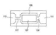
図14は、本実施の形態におけるマイクロポンプの第1の変形例の平面図である。図14を参照して、第1の変形例におけるマイクロポンプ100は、第1流路130の形状が、その幅が加圧室109から第1液室111に向かって大きくなっている。このため、加圧室109から第1液室111に液体が流れる場合の流路抵抗が、第1液室111から加圧室109に液体が流れる場合の流路抵抗よりも小さくなる。この結果、加圧室109を加圧する時間と、減圧する時間とが同じ場合には、液体がマクロには第2液室113から加圧室109を通って第1液室111に向かう方向に流れる。 FIG. 14 is a plan view of a first modification of the micropump in the present embodiment. Referring to FIG. 14, in the
また、加圧室109を加圧する時間を減圧する時間よりも短くすれば、液体はマクロには、第1液室111から加圧室109を通って第2液室113へ向かって流れることになる。 Further, if the time for pressurizing the pressurizing
図15は、本実施の形態におけるマイクロポンプ100の第1の変形例の駆動部120が圧電素子107に印加する電圧の一例を示す図である。図15(A)は、液体を加圧室109から第1液室111に向かう方向に搬送する場合の波形を示し、図15(B)は、液体を第1液室111から加圧室109に向かう方向に搬送する場合の波形を示す。図15(A)に示す波形は、正弦波である。この正弦波は、振動板105が共振点で振動するように圧電素子107に印加される電圧の波形である。その結果、この正弦波の電圧が圧電素子107に印加されると、液体がマクロには、第1流路130の方向性に従った方向、すなわち、第1液室111から加圧室109に向かう方向に流れることになる。 FIG. 15 is a diagram illustrating an example of a voltage applied to the
図15(B)に示す波形は、電圧が増加する期間t1が、電圧が減少する期間t2よりも短い。このため、加圧室109の容積が減少する期間が増加する期間よりも短い。その結果、加圧室109の容積が減少するときの第1流路115の差圧が、加圧室109の容積が増加するときの第1流路115の差圧よりも大きくなる。その結果、この波形の電圧が圧電素子107に印加されると、液体がマクロには、第1流路130の方向性に従った方向と逆の方向、すなわち、第1液室111から加圧室109に向かう方向に流れることになる。 In the waveform illustrated in FIG. 15B, the period t1 during which the voltage increases is shorter than the period t2 during which the voltage decreases. For this reason, the period during which the volume of the pressurizing
図16は、本実施の形態におけるマイクロポンプ100の第1の変形例の駆動部120が圧電素子107に印加する電圧の波形の別の例を示す図である。図16(A)は、液体を加圧室109から第1液室111に向かう方向に搬送する場合の波形を示し、図16(B)は、液体を第1液室111から加圧室109に向かう方向に搬送する場合の波形を示す。図16(A)を参照して、電圧の波形は矩形で表わされている。加圧室109の容積が増加する期間と減少する期間とが同じとなる。そして、第1流路115では、加圧室109の容積が増加する場合と減少する場合とで第1流路130の差圧の絶対値が同じになる。このため、第1流路130の方向性に従った方向、すなわち、加圧室109から第1液室111に向かう方向に液体が流れることになる。 FIG. 16 is a diagram illustrating another example of a waveform of a voltage applied to the
図16(B)を参照して、電圧が増加する期間t1が電圧が減少する期間t2よりも短い。また、期間t1と期間t2との間に電圧が変化しない期間t3が含まれる。電圧が増加する期間t1が電圧が減少する期間t2よりも短いため、加圧室109の容積が減少する期間t1が増加する期間t2よりも短くなる。その結果、期間t1における第1流路の差圧の絶対値が期間t2における第1流路130の差圧の絶対値よりも大きくなる。このため、マクロでは、液体が第1流路130の方向性に従った方向と逆の方向、すなわち、加圧室109から第2液室113に向かう方向に搬送される。 Referring to FIG. 16B, the period t1 during which the voltage increases is shorter than the period t2 during which the voltage decreases. In addition, a period t3 in which the voltage does not change is included between the period t1 and the period t2. Since the period t1 during which the voltage increases is shorter than the period t2 during which the voltage decreases, the period t1 during which the volume of the pressurizing
[マイクロポンプの第2の変形例]
図17は、本実施の形態におけるマイクロポンプ100の第2の変形例の平面図である。第1流路と第2流路とを相対的に比較して、差圧に対する流路抵抗の変化率に違いが認められるならば、第1流路に加えて第2流路にも方向性を持たせても問題ない。ただし、第1流路の差圧に対する流路抵抗の変化率が第2流路の差圧に対する流路抵抗の変化率よりも大きくなることが条件となる。第1流路および第2流路の双方に同じ方向性を持たせることにより、圧電素子107に正弦波を印加して駆動した場合に液体を搬送する効率がさらに改善される。[Second Modification of Micropump]
FIG. 17 is a plan view of a second modification of
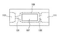
図17を参照して、第2流路131は、その形状が、第2液室113から加圧室109に向かって幅が広くなる形状となっている。このため、液体が第2液室113から加圧室109に流れるときの流路抵抗が、加圧室109から第2液室113に流れるときの流路抵抗よりも小さい。このため、加圧室109の容積を減少する期間と増加する期間とが同じであれば、マクロでは液体が第1流路130と第2流路131の方向性に従った方向、すなわち、第2液室113から加圧室109に向かう方向に流れる。 Referring to FIG. 17, the shape of
一方、加圧室109の容積が減少する期間を増加する期間よりも短くすれば、マクロでは液体が、第1流路130と第2流路131の方向性に従った方向と逆の方向、すなわち、第1液室111から加圧室109に向かう方向に流れる。 On the other hand, if the period in which the volume of the pressurizing
図18は、本実施の形態におけるマイクロポンプ100の第2の変形例の第1流路130および第2流路131それぞれの差圧と流路抵抗との関係を示す図である。図18(A)は第1流路130の場合を示し、図18(B)は第2流路131の場合を示す。図18を参照して、第1流路および第2流路ともに差圧が正の場合の流路抵抗が、差圧が負の場合の流路抵抗よりも小さくなっている。したがって、第1流路および第2流路が方向性を有することが示されている。また、第1流路の差圧の変化に対する流路抵抗の変化の割合が、第2流路の差圧の変化に対する流路抵抗の変化の割合よりも大きくなっている。このため、加圧室の容積を減少させる期間を増加させる期間よりも短くすることにより、増加させる期間と減少させる期間が同じ場合に液体が流れる方向とは逆の方向に液体を搬送することができる。 FIG. 18 is a diagram illustrating the relationship between the differential pressure and the channel resistance of each of the
以上説明したように本実施の形態におけるマイクロポンプは、液体の流れが急峻となるときに第1流路115,130のみに乱流を発生させるようにした。このため、2つの波形の電圧を切換えて圧電素子107を駆動することにより、マクロ的な流体の流れの方向を制御し、正逆両方向に液体を搬送することができる。 As described above, the micropump in the present embodiment generates turbulent flow only in the
また、従来のように逆止弁を開閉させる方式に比べて、応答性および耐久性が改善されるため、安定して駆動するマイクロポンプとすることができる。さらに、マイクロポンプの構成を簡単にすることができ、マイクロポンプ自体を小型化することができる。 In addition, since the responsiveness and durability are improved as compared with the conventional method of opening and closing the check valve, the micropump can be stably driven. Furthermore, the configuration of the micropump can be simplified, and the micropump itself can be reduced in size.
さらに、圧電素子107を駆動する電圧の1パルス信号当りの液送り量を微小にすることができるので、高い精度で脈動のない液送りをすることができる。 Furthermore, since the liquid feed amount per pulse signal of the voltage for driving the
なお、本実施の形態におけるマイクロポンプ100は、アクチュエータとして圧電素子107と振動板105とを貼り合わせたユニモルフ振動を用いたが、加圧室109の容積の増加または減少を繰返し行なうことができれば、ユニモルフ振動に限定されるものではない。たとえば、圧電素子の縦振動、横振動を用いてダイアフラムを振動する形態や、圧電素子のずり変形を用いるもの、または、圧電材料を用いたマイクロチューブを径方向へ縮小させる形態のものを用いてもよい。なお、圧電素子のずり変形とは、シェアモードとも呼ばれる変形で、圧電素子の分極方向と電界の方向とが直交するときに素子が斜めにずれる変形をいう。さらに、圧電素子以外に静電気力によってダイアフラムを変形させる方式や、振動子の一部に形状記憶合金を用いる形態のものを用いてもよい。 Note that the
今回開示された実施の形態はすべての点で例示であって制限的なものではないと考えられるべきである。本発明の範囲は上記した説明ではなくて特許請求の範囲によって示され、特許請求の範囲と均等の意味および範囲内でのすべての変更が含まれることが意図される。 The embodiment disclosed this time should be considered as illustrative in all points and not restrictive. The scope of the present invention is defined by the terms of the claims, rather than the description above, and is intended to include any modifications within the scope and meaning equivalent to the terms of the claims.
100 マイクロポンプ、101 基板、103 上側基板、105 振動板、107 圧電素子、109 加圧室、111 第1液室、113 第2液室、115 第1流路、117 第2流路、120 駆動部、131 障害物。 100 micro pump, 101 substrate, 103 upper substrate, 105 vibration plate, 107 piezoelectric element, 109 pressurizing chamber, 111 first liquid chamber, 113 second liquid chamber, 115 first flow path, 117 second flow path, 120
Claims (9)
Translated fromJapanese前記加圧室の内部の圧力を変化させるためのアクチュエータと、
前記加圧室に接続された第1流路および第2流路とを備え、
前記アクチュエータが第1の差圧を発生する場合における前記第1流路と前記第2流路との間の流路抵抗についての大小関係は、前記アクチュエータが前記第1の差圧から所定圧力だけ離れた第2の差圧を発生する場合における前記第1流路と前記第2流路との間の流路抵抗についての大小関係に対して逆転することを特徴とする、マイクロポンプ。A pressure chamber;
An actuator for changing the pressure inside the pressurizing chamber;
A first flow path and a second flow path connected to the pressurizing chamber;
When the actuator generates a first differential pressure, the magnitude relationship regarding the flow resistance between the first flow path and the second flow path is such that the actuator is only a predetermined pressure from the first differential pressure. A micropump which reverses with respect to the magnitude relation about channel resistance between said 1st channel and said 2nd channel in the case of generating the 2nd differential pressure apart.
前記第2流路に接続された第2液室とをさらに備え、
前記第1流路と前記第2流路とは、その断面形状が互いに同一であるとともに、その長さが異なることを特徴とする、請求項1〜3のいずれかに記載のマイクロポンプ。A first liquid chamber connected to the first flow path;
A second liquid chamber connected to the second flow path,
4. The micropump according to claim 1, wherein the first flow path and the second flow path have the same cross-sectional shape and different lengths. 5.
前記繰返しは、前記加圧室の体積を増加させる時間と減少させる時間とを異ならせることを特徴とする、請求項1〜6のいずれかに記載のマイクロポンプ。Driving means for driving the actuator to repeatedly change the volume of the pressurizing chamber between the first volume and the second volume at a predetermined interval;
The micro-pump according to claim 1, wherein the repetition makes the time for increasing the volume of the pressurizing chamberdifferent from the time for decreasing.
前記第1流路は、第1の方向の流路抵抗が前記第1の方向とは逆の第2の方向の流路抵抗よりも大きく、
前記駆動手段は、体積を増加させる時間と減少させる時間とが同じ第1の繰り返しと増加させる時間と減少させる時間とが異なる第2の繰り返しとで駆動可能であることを特徴とする、請求項1に記載のマイクロポンプ。Driving means for driving the actuator to repeatedly change the volume of the pressurizing chamber between the first volume and the second volume at a predetermined interval;
The first channel has a channel resistance in a first direction larger than a channel resistance in a second direction opposite to the first direction,
The driving means can be driven in a first repetition in which the time for increasing the volume and in the time for decreasing are the same, and in a second repetition in which the time for increasing and the time for decreasing are different. 2. The micropump according to 1.
Priority Applications (1)
| Application Number | Priority Date | Filing Date | Title |
|---|---|---|---|
| JP2004319256AJP4645159B2 (en) | 2004-11-02 | 2004-11-02 | Micro pump |
Applications Claiming Priority (1)
| Application Number | Priority Date | Filing Date | Title |
|---|---|---|---|
| JP2004319256AJP4645159B2 (en) | 2004-11-02 | 2004-11-02 | Micro pump |
Related Parent Applications (1)
| Application Number | Title | Priority Date | Filing Date |
|---|---|---|---|
| JP2000143124ADivisionJP3629405B2 (en) | 2000-05-16 | 2000-05-16 | Micro pump |
Publications (3)
| Publication Number | Publication Date |
|---|---|
| JP2005098304A JP2005098304A (en) | 2005-04-14 |
| JP2005098304A5 JP2005098304A5 (en) | 2007-07-19 |
| JP4645159B2true JP4645159B2 (en) | 2011-03-09 |
Family
ID=34464267
Family Applications (1)
| Application Number | Title | Priority Date | Filing Date |
|---|---|---|---|
| JP2004319256AExpired - Fee RelatedJP4645159B2 (en) | 2004-11-02 | 2004-11-02 | Micro pump |
Country Status (1)
| Country | Link |
|---|---|
| JP (1) | JP4645159B2 (en) |
Families Citing this family (1)
| Publication number | Priority date | Publication date | Assignee | Title |
|---|---|---|---|---|
| WO2007013287A1 (en)* | 2005-07-27 | 2007-02-01 | Kyushu Institute Of Technology | Valveless micropump |
Family Cites Families (5)
| Publication number | Priority date | Publication date | Assignee | Title |
|---|---|---|---|---|
| SE508435C2 (en)* | 1993-02-23 | 1998-10-05 | Erik Stemme | Diaphragm pump type pump |
| DE19648695C2 (en)* | 1996-11-25 | 1999-07-22 | Abb Patent Gmbh | Device for the automatic and continuous analysis of liquid samples |
| DE59707378D1 (en)* | 1996-12-11 | 2002-07-04 | Gesim Ges Fuer Silizium Mikros | microejection |
| JP2995401B2 (en)* | 1998-03-16 | 1999-12-27 | セイコーインスツルメンツ株式会社 | Micropump and method of manufacturing micropump |
| JPH11324931A (en)* | 1998-05-13 | 1999-11-26 | Akebono Brake Res & Dev Center Ltd | Control method of motor-driven pump |
- 2004
- 2004-11-02JPJP2004319256Apatent/JP4645159B2/ennot_activeExpired - Fee Related
Also Published As
| Publication number | Publication date |
|---|---|
| JP2005098304A (en) | 2005-04-14 |
Similar Documents
| Publication | Publication Date | Title |
|---|---|---|
| JP3629405B2 (en) | Micro pump | |
| JP2001322099A5 (en) | ||
| Xia et al. | Electroactive polymer based microfluidic pump | |
| US8297947B2 (en) | Fluid disc pump | |
| US10349182B2 (en) | Micromechanical piezoelectric actuators for implementing large forces and deflections | |
| US8444396B2 (en) | Fluid transferring system and micropump suitable therefor | |
| AU2009347422B2 (en) | Pump with disc-shaped cavity | |
| EP2758666B1 (en) | Dual-cavity pump | |
| US9752565B2 (en) | Systems and methods for supplying reduced pressure using a disc pump with electrostatic actuation | |
| JP4873014B2 (en) | Piezoelectric micro blower | |
| JP4531563B2 (en) | Peristaltic micropump | |
| JP4793441B2 (en) | Piezoelectric micro pump | |
| Van der Wijngaart et al. | The first self-priming and bi-directional valve-less diffuser micropump for both liquid and gas | |
| EP2438335A1 (en) | Valve | |
| JP2005299597A (en) | Micro pump | |
| Lee et al. | Bidirectional pumping properties of a peristaltic piezoelectric micropump with simple design and chemical resistance | |
| JPH02149778A (en) | piezoelectric micro pump | |
| US20140238522A1 (en) | Piezoelectric driven oscillating surface | |
| JP4645159B2 (en) | Micro pump | |
| JP4935159B2 (en) | Micro pump | |
| CN110461608A (en) | droplet ejection device | |
| Wen et al. | A valveless micro impedance pump driven by PZT actuation | |
| Tracey et al. | Dual independent displacement-amplified micropumps with a single actuator | |
| JP2003139064A (en) | Small pump | |
| Cui et al. | Modeling and numerical analysis of a circular piezoelectric actuator for valveless micropumps |
Legal Events
| Date | Code | Title | Description |
|---|---|---|---|
| A621 | Written request for application examination | Free format text:JAPANESE INTERMEDIATE CODE: A621 Effective date:20070515 | |
| A521 | Request for written amendment filed | Free format text:JAPANESE INTERMEDIATE CODE: A523 Effective date:20070601 | |
| A977 | Report on retrieval | Free format text:JAPANESE INTERMEDIATE CODE: A971007 Effective date:20100401 | |
| A131 | Notification of reasons for refusal | Free format text:JAPANESE INTERMEDIATE CODE: A131 Effective date:20100629 | |
| A521 | Request for written amendment filed | Free format text:JAPANESE INTERMEDIATE CODE: A523 Effective date:20100824 | |
| TRDD | Decision of grant or rejection written | ||
| A01 | Written decision to grant a patent or to grant a registration (utility model) | Free format text:JAPANESE INTERMEDIATE CODE: A01 Effective date:20101109 | |
| A01 | Written decision to grant a patent or to grant a registration (utility model) | Free format text:JAPANESE INTERMEDIATE CODE: A01 | |
| A61 | First payment of annual fees (during grant procedure) | Free format text:JAPANESE INTERMEDIATE CODE: A61 Effective date:20101122 | |
| FPAY | Renewal fee payment (event date is renewal date of database) | Free format text:PAYMENT UNTIL: 20131217 Year of fee payment:3 | |
| R150 | Certificate of patent or registration of utility model | Free format text:JAPANESE INTERMEDIATE CODE: R150 | |
| S531 | Written request for registration of change of domicile | Free format text:JAPANESE INTERMEDIATE CODE: R313531 | |
| S533 | Written request for registration of change of name | Free format text:JAPANESE INTERMEDIATE CODE: R313533 | |
| R350 | Written notification of registration of transfer | Free format text:JAPANESE INTERMEDIATE CODE: R350 | |
| LAPS | Cancellation because of no payment of annual fees |