JP4644611B2 - Vehicle center panel structure - Google Patents
Vehicle center panel structureDownload PDFInfo
- Publication number
- JP4644611B2 JP4644611B2JP2006041059AJP2006041059AJP4644611B2JP 4644611 B2JP4644611 B2JP 4644611B2JP 2006041059 AJP2006041059 AJP 2006041059AJP 2006041059 AJP2006041059 AJP 2006041059AJP 4644611 B2JP4644611 B2JP 4644611B2
- Authority
- JP
- Japan
- Prior art keywords
- operation button
- center panel
- operator
- panel
- panel structure
- Prior art date
- Legal status (The legal status is an assumption and is not a legal conclusion. Google has not performed a legal analysis and makes no representation as to the accuracy of the status listed.)
- Expired - Fee Related
Links
Images


Landscapes
- Instrument Panels (AREA)
Description
Translated fromJapanese本発明は、車両のセンターパネル構造体に係わり、特に、車両のインストルメントパネルのほぼ中央部に設けられたセンターパネル構造体に関する。 The present invention relates to a vehicle center panel structure, and more particularly, to a center panel structure provided at a substantially central portion of a vehicle instrument panel.
近年、自動車のインテリアデザインに独自性が要求されており、計器盤の操作スイッチ(操作ボタン)に関しても機能面のみならずインテリアの一部としてのデザイン部品に位置付けられている。
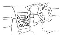
例えば、図1には、このようなデザイン要求に基づいて設計された車両のセンターパネルの例が示されており、DINと呼ばれる既製サイズのオーディオモジュール操作パネルを廃し、独自の意匠パネルとして形成されている。In recent years, the interior design of automobiles has been required to be unique, and the operation switches (operation buttons) on the instrument panel are positioned not only in terms of function but also as design parts as part of the interior.
For example, FIG. 1 shows an example of a vehicle center panel designed on the basis of such a design requirement, and an off-the-shelf audio module operation panel called DIN is abolished and formed as a unique design panel. ing.
ところで、この種の操作パネル(以下「センターパネル」と言う)のスイッチ構造(操作ボタン構造)は、例えば、特開平8−207622で開示されたものを図2に示すように、意匠面を形成するパネル50と押動可能に配設せしめたボタン52及びボタン54等から構成されている。
さらに、他の例として、特許第3466955号に開示されたものを図3に示すように、センターパネルは、多数のボタン56と、これらのボタン56の表面上に形成された文字や図柄を照明するための、非照明部位への漏洩光を遮光する目的で配設した遮光ケース58を備えている。By the way, the switch structure (operation button structure) of this type of operation panel (hereinafter referred to as “center panel”) has a design surface as shown in FIG. 2, for example, as disclosed in JP-A-8-207622. And a
Further, as another example, as shown in FIG. 3 as disclosed in Japanese Patent No. 3466955, the center panel illuminates a large number of
次に、図4により、上述した従来技術をより詳細に説明する。
図4は、オーディオの機能を操作する操作スイッチ(操作ボタン)を備えた従来のセンターパネルを示す断面図である。図4において、60はセンターパネル全体を形成する意匠面パネルである。また、62は各種操作ボタンで、パネル60の背面から装着して、押動可能に配置されている。さらに、これらのボタン62の背面には遮光ケース64を介してLEDとスイッチ68とを搭載したプリント配線板70が保持されている。
このようにして、LED66によってボタン62の表面に形成された表示文字の夜間照明を行うと共に、ボタン62を押圧してスイッチ68の電気接点を押動することによってプリント配線板70から特定のボタンの操作情報を電気的に知り得るように構成されている。Next, the above-described prior art will be described in more detail with reference to FIG.
FIG. 4 is a cross-sectional view showing a conventional center panel provided with operation switches (operation buttons) for operating audio functions. In FIG. 4, 60 is a design surface panel that forms the entire center panel.
In this manner, the display characters formed on the surface of the
ところで、ナビディスプレー等に用いられるタッチパネルが知られているが、このタッチパネルは非作動時に何らデザイン的要素を持っておらず、車両のインテリアデザインとしての役割を果たす事はできない。 By the way, although the touch panel used for a navigation display etc. is known, this touch panel has no design element at the time of non-operation, and cannot play the role as an interior design of a vehicle.
上述した従来のセンターパネル構造は、操作ボタン、遮光ケース、パネル等多くの構成部材を必要とし、かつ、可動部材である操作ボタンは、パネルとの隙間精度要求及び押動時の引っ掛かり、戻り不良等を無くす必要があるので、高い寸法精度で成型する事が求められる。 The conventional center panel structure described above requires many components such as an operation button, a light shielding case, and a panel, and the operation button that is a movable member requires a gap accuracy with the panel and is caught when pushed and returned poorly. Therefore, it is required to mold with high dimensional accuracy.
同時に、パネル、操作ボタン及び遮光ケース類は樹脂成型材料によって構成されるため、成型部品点数に応じた成型コストが発生し、かつ部品種類数と同じ成型金型を必要とするという問題がある。 At the same time, since the panel, the operation buttons, and the light shielding cases are made of a resin molding material, there is a problem in that a molding cost corresponding to the number of molded parts is generated and the same molding die as the number of parts is required.
また、遮光性能/照明性能及び釦の押動フィーリングの改善を含めた改善工数は膨大なものとなる。かかる構造により、従来のセンターパネルは、部材価格の増大、金型費用の増加、開発費用の増加を招き、結果的に製品価格の増加を招いていた。 In addition, the number of man-hours for improvement including improvement of the light shielding performance / illumination performance and the push feeling of the button becomes enormous. With such a structure, the conventional center panel causes an increase in material price, an increase in mold cost, and an increase in development cost, resulting in an increase in product price.
そこで、本発明は、上述した従来技術の問題点を解決した車両のセンターパネル構造体を提供することを目的としている。 Accordingly, an object of the present invention is to provide a vehicle center panel structure that solves the above-described problems of the prior art.
上記の目的を達成するために、本発明は、車両のインストルメントパネルのほぼ中央部に設けられたセンターパネル構造体であって、各種の操作を行うための三次元の任意の意匠形状を持つ複数の操作ボタン部及びパネル本体部とが樹脂成型材料により一体成型されたセンターパネル部と、操作ボタン部の各々に設けられ操作者がその操作ボタン部を操作したことを検出する検出手段と、操作者がどの操作ボタンを操作したかを検知し且つこの検知信号を出力する検知手段と、を有することを特徴としている。 In order to achieve the above object, the present invention is a center panel structure provided at substantially the center of an instrument panel of a vehicle, and has a three-dimensional arbitrary design shape for performing various operations. A center panel unit in which a plurality of operation button units and a panel main body unit are integrally formed of a resin molding material, and a detection unit that is provided in each of the operation button units and detects that an operator operates the operation button unit, And detecting means for detecting which operation button the operator has operated and outputting this detection signal.
また、本発明において、好ましくは、上記検出手段は、各操作ボタン部に設けられた電気導電性材料からなる電極であり、この電極の静電容量の変化から操作者の各操作ボタン部の操作を検出する。
また、本発明において、好ましくは、上記検出手段は、各操作ボタン部に設けられた発光素子と受光素子とからなる光検出手段であり、この受光素子の出力信号の変化から操作者の各操作ボタン部の操作を検出する。
さらに、本発明は、好ましくは、更に、パネル本体部の上記操作ボタン部の近傍に設けられ、その操作ボタン部に加わる操作者の押圧力を検出する押圧力検出手段とを有する。In the present invention, it is preferable that the detection means is an electrode made of an electrically conductive material provided in each operation button unit, and an operation of each operation button unit by an operator is performed based on a change in capacitance of the electrode. Is detected.
In the present invention, it is preferable that the detection unit is a light detection unit including a light emitting element and a light receiving element provided in each operation button unit, and each operation of the operator is performed based on a change in an output signal of the light receiving element. Detects button operation.
Furthermore, the present invention preferably further includes a pressing force detection unit that is provided in the vicinity of the operation button portion of the panel main body portion and detects the pressing force of the operator applied to the operation button portion.
また、本発明において、好ましくは、検出手段である電極は、金属箔シートで形成されている。 In the present invention, preferably, the electrode that is the detection means is formed of a metal foil sheet.
さらに、本発明は、車両のインストルメントパネルのほぼ中央部に設けられたセンターパネル構造体であって、各種の操作を行うための三次元の任意の意匠形状を持つ複数の操作ボタン部を備えたセンターパネル部と、操作ボタン部の各々に設けられ操作者がその操作ボタン部を操作したことを検出する金属箔シートの検出電極と、操作者がどの操作ボタンを操作したかを検知し且つこの検知信号を出力する検知手段と、を有することを特徴としている。 Furthermore, the present invention is a center panel structure provided at substantially the center of an instrument panel of a vehicle, and includes a plurality of operation button portions having arbitrary three-dimensional design shapes for performing various operations. The center panel part, the detection button of the metal foil sheet which is provided in each of the operation button parts and detects that the operator has operated the operation button part, and which operation button the operator has operated is detected. And a detection means for outputting the detection signal.
本発明によれば、操作ボタン部とパネル本体部を一体成型したので、操作ボタン部とパネル本体部との間隙が無くなるので、遮光ケースを不要とすることができる。 According to the present invention, since the operation button portion and the panel main body portion are integrally molded, there is no gap between the operation button portion and the panel main body portion, so that a light shielding case can be eliminated.
本発明によれば、センターパネル部に三次元の任意意匠を形成可能であるから車両のインテリアデザイン要求を満たす事ができるにも関わらず、その構成部品はセンターパネル部とプリント配線板とだけにする事が可能で、上述した部材費用の大幅な削減と金型費用、開発費用をも同時に削減可能となる。 According to the present invention, since a three-dimensional design can be formed on the center panel portion, the vehicle interior design requirements can be satisfied, but the components are only on the center panel portion and the printed wiring board. This makes it possible to reduce the above-mentioned material costs, mold costs, and development costs at the same time.
また、本発明のセンターパネル構造体は、液晶デスプレー上に配したタッチパネル等とは異なり、非作動時にも操作釦の配置を視認可能である事、また立体的釦形状によるブラインドタッチをも可能にし得るといった効果も備えている。 In addition, the center panel structure of the present invention, unlike a touch panel arranged on a liquid crystal display, makes it possible to visually recognize the arrangement of operation buttons even when not in operation, and also enables a blind touch with a three-dimensional button shape. It also has the effect of gaining.
さらに、本発明のセンターパネル構造体は、操作ボタン部とパネル本体部とを一体成型とので、従来存在していた両者間の機械的隙間が無いことによる被水耐性が格段に向上するというメリットもある。 Furthermore, since the center panel structure of the present invention is integrally molded with the operation button part and the panel body part, the water resistance due to the absence of a mechanical gap between the two has been greatly improved. There is also.
次に、本発明の車両のセンターパネル構造体の第1実施形態を図5〜図7を参照して説明する。 Next, a first embodiment of a vehicle center panel structure according to the present invention will be described with reference to FIGS.
図5は、車両のインストルメントパネルのほぼ中央部に配設され計器盤の操作パネルを構成する本発明のセンターパネルの第1実施形態を示す断面図である。
図5に示すように、センターパネル部1は、樹脂成型材料により一体形成されたパネル本体部2と複数の操作ボタン部4とから構成されている。パネル本体部2は、任意の部位に所定形状の操作釦形状を三次元(立体的)に成型した操作ボタン部4を具備している。FIG. 5 is a cross-sectional view showing a first embodiment of the center panel of the present invention, which is disposed at substantially the center of the instrument panel of the vehicle and constitutes the operation panel of the instrument panel.
As shown in FIG. 5, the
プリント配線板6が、パネル本体部2の背面に固定され、このプリント配線板6には、操作ボタン部4を背面から照明するLED8及び所望の電子回路部品を配設されている。 A printed
図6は、操作ボタン部4の拡大図及び断面図である。図6に示すように、操作ボタン部4の表面は任意の塗装色で塗装されると共に、操作機能表示文字(POWER)10がレーザカットにより形成されている。ここで、操作ボタン部4は、三次元形状に形成されているが、具体的に言えば、周囲に溝が形成されており、溝から突出し、さらに、表面もなだらかに隆起した形状となっている。さらに、表示文字部分に凹凸を形成するようにしても良い。 FIG. 6 is an enlarged view and a sectional view of the
操作ボタン部4の板厚内にインサート成型された電気導電性材料より成る検出電極12が設けられており、この検出電極12には、リード14が接続され、プリント配線板6に向かって突出している。なお、検出電極12は、操作ボタン部4の背面側に設けても良い。 A
図7は第1実施形態におけるプリント配線板6上に形成せしめた電気回路構成を示すブロック図である。図7に示すように、プリント配線板6上に形成せしめた電気回路は、12のリード14と接続せしめた静電容量検出回路16と、この静電容量検出回路16の出力信号を入力せしめて、操作ボタン部4の操作状態を判定するマイクロコンピュータ18と、このマイクロコンピュータ18の検出結果を、図示しないワイヤーハーネスを介して電気的に出力する端子20と、ブザー等の報知手段22を備えている。 FIG. 7 is a block diagram showing an electric circuit configuration formed on the printed
またLED8は、マイクロコンピュータ18によって制御され操作ボタン部4の背面から夜間照明光を供給する。
なお、検出電極12及びLED8は、センターパネル部1上に要求される操作機能数、すなわち操作ボタン部4の数に対応して複数個配設されている。The
A plurality of
以上の構成によって、センターパネル部1の意匠面においては所望の操作釦形状を配した三次元形状の任意意匠を形成することができる。 With the above configuration, a three-dimensional arbitrary design having a desired operation button shape can be formed on the design surface of the
そして、複数配した操作ボタン部4のうち、操作者が意図した所望の機能を表示する部位(例えば“POWER”)の表面を指で触れる事によって、この操作ボタン部4の検出電極12と、図示しない電気的接地との間の静電容量が変化する。
従って、かかる静電容量の変化を静電容量検出回路16が検出する事によってマイクロコンピュータ18は、どの操作ボタン部4が押圧されたかを検知し、その結果を端子20から図示しないシリアル信号等の電気的伝送手段によって送出する。
また、マイクロコンピュータ18は押圧状態を検出すると同時に報知手段22を作動させて操作者へのフィードバックを行う。Then, by touching the surface of a portion (for example, “POWER”) that displays a desired function intended by the operator among the plurality of
Accordingly, when the
Further, the
なお、静電容量検出回路16としては、既知静電容量−周波数変換回路、あるいは静電容量−電圧変換回路等、多様な回路方式が利用可能である。 As the
また、本実施形態では静電容量検出回路16の出力を受けて、マイクロコンピュータ18によって操作ボタン部4の押圧状態を判定するものとしたが、マイクロコンピュータ18の代わりに、別の信号処理回路手段、例えばアナログ演算回路、コンパレータ回路等が採用可能である。 In this embodiment, the
さらには、本実施形態においては、複数存在する操作ボタン部4のどの部位(操作ボタン)が操作されたかを、検出電極12によって静電容量の変化として検出するものとしたが、この代わりに、各操作ボタン部毎に発光素子と受光素子を配設せしめ、操作者の指が近接した時に生じる受光素子の出力変化を利用して操作部位を特定するようにしても良い。 Furthermore, in the present embodiment, it is assumed that which part (operation button) of the plurality of
次に、図8を参照して、本発明の第2実施形態を説明する。 Next, a second embodiment of the present invention will be described with reference to FIG.
第1実施形態においてはセンターパネル部1上に配設した操作ボタン部4を操作者が指で触れた事によってその操作ボタン部4の操作状態を検出するように構成した。
この場合、例えば、この操作者が意図せず操作ボタン部4を触れた場合にも、静電容量検出回路16の出力状態が変化し、結果的に対応する電子機器の機能が応動するといった懸念がある。In the first embodiment, the
In this case, for example, even when the operator touches the
この問題点を解決するために、第2実施形態においては、操作ボタン部4への押圧状態を第1実施形態と同様にして検出する事に加えて、センターパネル部1の全体にかかる応力(押圧力)の状態を検出する応力検出手段(押圧力検出手段)30を配設した。 In order to solve this problem, in the second embodiment, in addition to detecting the pressing state of the
このようにして、静電容量検出回路16によって操作者による操作ボタン部4の押圧部位を特定し、かつ応力検出手段30とによって操作者の押圧力を測定する。
従って、操作者が意図せず操作ボタン部4に触れた場合と、意図して所望の操作力で押した場合とを区別可能であるから、いわゆる誤操作の可能性を大幅に削減する事ができる。In this manner, the pressing portion of the
Accordingly, since it is possible to distinguish between the case where the operator unintentionally touches the
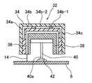
次に、図9を参照して、本発明の第3実施形態を説明する。
この第3実施形態においては、上述した第1及び第2実施形態と同様に、操作ボタン部とパネル本体部とを樹脂成型材料により一体成型してもよく、又は、第1及び第2実施形態と異なり、操作ボタン部とパネル本体部とをそれぞれ樹脂成型材料で別々に形成するようにしてもよい。ここでは、操作ボタン部とパネル本体部とをそれぞれ樹脂成型材料で別々に形成した例を説明する。Next, a third embodiment of the present invention will be described with reference to FIG.
In the third embodiment, similarly to the first and second embodiments described above, the operation button portion and the panel main body portion may be integrally formed of a resin molding material, or the first and second embodiments. Unlike the above, the operation button part and the panel main body part may be separately formed of a resin molding material. Here, an example will be described in which the operation button part and the panel main body part are separately formed of a resin molding material.
この第3実施形態において、操作ボタン部32は、全体的に円筒形でその円形頂面に模様が付されており、印刷フィルム34、金属箔シートからなる検出電極36、射出成形部材38から構成されている。
印刷フィルム34は、支持フィルム34a、この支持フィルム34aの内側面に形成された模様34b、この模様模様34bを被覆するバインダー層34cとから構成されている。ここで、模様34bは、さらに、「POWER」等の文字34b−1と、この文字34b-1を包囲するように配置される背景地34b−2とから構成されている。In this third embodiment, the
The
操作ボタン部32の検出電極36には、リード14が接続されており、プリント配線板6に向かって突出し、タッチパネルスイッチを構成している。
第3実施形態においては、さらに、射出成形部材38の底部には、プッシュロッド40が取り付けられ、このプッシュロッド40の下端部40aがプリント配線板6に取り付けられたコンタクトスイッチ40に当接するように配置され、これにより、プッシュ式スイッチを構成している。A lead 14 is connected to the
In the third embodiment, a
次に、第3実施形態の作用を説明する。第3実施形態においては、操作者により、操作ボタン部32が押し下げられてコンタクトスイッチ40によってスイッチがオン、オフされるか、或いは、操作者の指がタッチパネルスイッチ36,14に触れてスイッチがオン、オフされるかのいずれによってもスイッチがオン、オフされるので、作動が確実になる。 Next, the operation of the third embodiment will be described. In the third embodiment, the operator pushes down the
特に、本実施形態のように、操作ボタン部32のような円筒形状の比較的小さなボタンにおけるタッチパネルスイッチでは、操作ボタン部32にタッチする操作者の指の面積は小さいので、通常、指と検出電極との間に形成される静電容量の変化が小さく、タッチを検出し難いのであるが、本実施形態では、検出電極36を金属箔シートで構成しているので、指と検出電極36との間には(薄い)印刷フィルム32しか存在しないので、大きな静電容量変化が生じ、タッチ検出感度を向上させることができる。 In particular, in the touch panel switch of a relatively small cylindrical button such as the
なお、第1及び第2実施形態においても、第3実施形態と同様に、検出電極12を金属箔シートにより形成してもよい。 In the first and second embodiments, the
1 センターパネル部
2 パネル本体部
4 操作ボタン部
6 プリント配線板
8 LED
10 操作機能表示文字
12 検出電極
14 リード
16 静電容量検出回路
18 マイクロコンピュータ
20 端子
22 報知手段
30 応力検出手段(押圧力検出手段)
32 操作ボタン部
34 印刷フィルム
36 検出電極
38 射出成形部材1
DESCRIPTION OF
32
Claims (2)
Translated fromJapanese各種の操作を行うための三次元の任意の意匠形状を持つ複数の操作ボタン部及びパネル本体部とが樹脂成型材料により一体成型されたセンターパネル部と、
上記操作ボタン部の各々に設けられ操作者がその操作ボタン部を操作したことを検出する検出手段と、
操作者がどの操作ボタンを操作したかを検知し且つこの検知信号を出力する検知手段と、
上記パネル本体部の上記操作ボタン部の近傍に設けられ、上記操作者が上記操作ボタン部を押圧することにより上記センターパネル部の全体にかかる押圧力を検出する押圧力検出手段とを有し、
上記検出手段は、各操作ボタン部に設けられた電気導電性材料からなる電極であり、この電極の静電容量の変化から操作者の各操作ボタン部の操作を検出する
ことを特徴とする車両のセンターパネル構造体。A center panel structure provided in a substantially central portion of a vehicle instrument panel,
A center panel portion in which a plurality of operation button portions and panel body portions having arbitrary three-dimensional design shapes for performing various operations are integrally formed of a resin molding material,
A detecting means provided in each of the operation button portions to detect that an operator has operated the operation button portion;
Detection means for detecting which operation button the operator has operated and outputting this detection signal;
Provided in the vicinity of the operation button portion of the panel body,possessa pressing force detecting means for the operator to detect the pressing force applied to the whole of the center panel portion by pressing the operation buttonunit,
The detection means is an electrode made of an electrically conductive material provided in each operation button unit, and detects an operation of each operation button unit by an operator from a change in capacitance of the electrode. A vehicle center panel structure.
Priority Applications (1)
| Application Number | Priority Date | Filing Date | Title |
|---|---|---|---|
| JP2006041059AJP4644611B2 (en) | 2005-02-25 | 2006-02-17 | Vehicle center panel structure |
Applications Claiming Priority (2)
| Application Number | Priority Date | Filing Date | Title |
|---|---|---|---|
| JP2005051256 | 2005-02-25 | ||
| JP2006041059AJP4644611B2 (en) | 2005-02-25 | 2006-02-17 | Vehicle center panel structure |
Publications (2)
| Publication Number | Publication Date |
|---|---|
| JP2006264674A JP2006264674A (en) | 2006-10-05 |
| JP4644611B2true JP4644611B2 (en) | 2011-03-02 |
Family
ID=37201066
Family Applications (1)
| Application Number | Title | Priority Date | Filing Date |
|---|---|---|---|
| JP2006041059AExpired - Fee RelatedJP4644611B2 (en) | 2005-02-25 | 2006-02-17 | Vehicle center panel structure |
Country Status (1)
| Country | Link |
|---|---|
| JP (1) | JP4644611B2 (en) |
Families Citing this family (2)
| Publication number | Priority date | Publication date | Assignee | Title |
|---|---|---|---|---|
| FR2923177B1 (en)* | 2007-11-06 | 2009-12-25 | Visteon Global Tech Inc | METHOD FOR ASSEMBLING A COMPOSITE WORKPIECE |
| KR102403356B1 (en)* | 2017-11-01 | 2022-06-02 | 현대자동차주식회사 | Control panel for vehicle |
Family Cites Families (6)
| Publication number | Priority date | Publication date | Assignee | Title |
|---|---|---|---|---|
| JPH0789150B2 (en)* | 1986-03-27 | 1995-09-27 | アイシン精機株式会社 | Personnel detection device |
| JP2000006687A (en)* | 1998-06-25 | 2000-01-11 | Yazaki Corp | In-vehicle equipment switch safety operation system |
| JP2000177430A (en)* | 1998-12-21 | 2000-06-27 | Harness Syst Tech Res Ltd | Vehicle instrumentation |
| JP3668834B2 (en)* | 1999-10-20 | 2005-07-06 | トヨタ自動車株式会社 | Vehicle display device |
| JP3988443B2 (en)* | 2001-11-28 | 2007-10-10 | 豊田合成株式会社 | Manufacturing method of resin molding with built-in switch for automobile interior |
| JP2004026046A (en)* | 2002-06-26 | 2004-01-29 | Clarion Co Ltd | Operating device for on-vehicle information equipment |
- 2006
- 2006-02-17JPJP2006041059Apatent/JP4644611B2/ennot_activeExpired - Fee Related
Also Published As
| Publication number | Publication date |
|---|---|
| JP2006264674A (en) | 2006-10-05 |
Similar Documents
| Publication | Publication Date | Title |
|---|---|---|
| US8531407B2 (en) | Input apparatus | |
| KR101156315B1 (en) | Slide pad membrane | |
| US7595791B2 (en) | Input device | |
| JP2010165618A (en) | Capacitance type input device and method of manufacturing the same | |
| US6530283B2 (en) | Force sensor | |
| CN103947113B (en) | Operation device | |
| CN108944661B (en) | Control panels for motor vehicles | |
| JP6344852B2 (en) | Rotating operation type electric parts | |
| CN101192485A (en) | contactless input device | |
| JP2010120487A (en) | In-cabin switch gear | |
| JP2008305766A (en) | Touch switch structure | |
| JP2016120890A (en) | Vehicular switching device | |
| US20090179872A1 (en) | Movable contact body and switch using same | |
| CN105730320B (en) | Switching device | |
| JP5993889B2 (en) | Capacitance input device and method for manufacturing capacitance input device | |
| JP4644611B2 (en) | Vehicle center panel structure | |
| EP3667691B1 (en) | Input operation device | |
| EP1892737A1 (en) | Touchpad | |
| JPWO2015133135A1 (en) | Switch device | |
| KR101106278B1 (en) | Complex input device with touch function | |
| JP6392504B2 (en) | Control panel | |
| JP2013232081A (en) | Touch panel input operation device | |
| JP6218252B2 (en) | Input device | |
| JP2014127017A (en) | Touch panel input operation device | |
| KR20150085396A (en) | Complex-type input device with touch sensing features |
Legal Events
| Date | Code | Title | Description |
|---|---|---|---|
| A621 | Written request for application examination | Free format text:JAPANESE INTERMEDIATE CODE: A621 Effective date:20081014 | |
| A977 | Report on retrieval | Free format text:JAPANESE INTERMEDIATE CODE: A971007 Effective date:20100430 | |
| A131 | Notification of reasons for refusal | Free format text:JAPANESE INTERMEDIATE CODE: A131 Effective date:20100510 | |
| A521 | Request for written amendment filed | Free format text:JAPANESE INTERMEDIATE CODE: A523 Effective date:20100705 | |
| TRDD | Decision of grant or rejection written | ||
| A01 | Written decision to grant a patent or to grant a registration (utility model) | Free format text:JAPANESE INTERMEDIATE CODE: A01 Effective date:20101115 | |
| A01 | Written decision to grant a patent or to grant a registration (utility model) | Free format text:JAPANESE INTERMEDIATE CODE: A01 | |
| A61 | First payment of annual fees (during grant procedure) | Free format text:JAPANESE INTERMEDIATE CODE: A61 Effective date:20101206 | |
| R150 | Certificate of patent or registration of utility model | Ref document number:4644611 Country of ref document:JP Free format text:JAPANESE INTERMEDIATE CODE: R150 Free format text:JAPANESE INTERMEDIATE CODE: R150 | |
| FPAY | Renewal fee payment (event date is renewal date of database) | Free format text:PAYMENT UNTIL: 20131210 Year of fee payment:3 | |
| R250 | Receipt of annual fees | Free format text:JAPANESE INTERMEDIATE CODE: R250 | |
| R250 | Receipt of annual fees | Free format text:JAPANESE INTERMEDIATE CODE: R250 | |
| S531 | Written request for registration of change of domicile | Free format text:JAPANESE INTERMEDIATE CODE: R313531 | |
| R350 | Written notification of registration of transfer | Free format text:JAPANESE INTERMEDIATE CODE: R350 | |
| R250 | Receipt of annual fees | Free format text:JAPANESE INTERMEDIATE CODE: R250 | |
| R250 | Receipt of annual fees | Free format text:JAPANESE INTERMEDIATE CODE: R250 | |
| R250 | Receipt of annual fees | Free format text:JAPANESE INTERMEDIATE CODE: R250 | |
| R250 | Receipt of annual fees | Free format text:JAPANESE INTERMEDIATE CODE: R250 | |
| R250 | Receipt of annual fees | Free format text:JAPANESE INTERMEDIATE CODE: R250 | |
| LAPS | Cancellation because of no payment of annual fees |