JP4644063B2 - Pipe connection structure - Google Patents
Pipe connection structureDownload PDFInfo
- Publication number
- JP4644063B2 JP4644063B2JP2005215838AJP2005215838AJP4644063B2JP 4644063 B2JP4644063 B2JP 4644063B2JP 2005215838 AJP2005215838 AJP 2005215838AJP 2005215838 AJP2005215838 AJP 2005215838AJP 4644063 B2JP4644063 B2JP 4644063B2
- Authority
- JP
- Japan
- Prior art keywords
- male
- female
- connection structure
- pipe connection
- locking member
- Prior art date
- Legal status (The legal status is an assumption and is not a legal conclusion. Google has not performed a legal analysis and makes no representation as to the accuracy of the status listed.)
- Expired - Fee Related
Links
Images


Classifications
- F—MECHANICAL ENGINEERING; LIGHTING; HEATING; WEAPONS; BLASTING
- F16—ENGINEERING ELEMENTS AND UNITS; GENERAL MEASURES FOR PRODUCING AND MAINTAINING EFFECTIVE FUNCTIONING OF MACHINES OR INSTALLATIONS; THERMAL INSULATION IN GENERAL
- F16L—PIPES; JOINTS OR FITTINGS FOR PIPES; SUPPORTS FOR PIPES, CABLES OR PROTECTIVE TUBING; MEANS FOR THERMAL INSULATION IN GENERAL
- F16L33/00—Arrangements for connecting hoses to rigid members; Rigid hose-connectors, i.e. single members engaging both hoses
- F16L33/22—Arrangements for connecting hoses to rigid members; Rigid hose-connectors, i.e. single members engaging both hoses with means not mentioned in the preceding groups for gripping the hose between inner and outer parts
- F16L33/227—Arrangements for connecting hoses to rigid members; Rigid hose-connectors, i.e. single members engaging both hoses with means not mentioned in the preceding groups for gripping the hose between inner and outer parts the hose being introduced into or onto the connecting member and automatically locked
- F—MECHANICAL ENGINEERING; LIGHTING; HEATING; WEAPONS; BLASTING
- F16—ENGINEERING ELEMENTS AND UNITS; GENERAL MEASURES FOR PRODUCING AND MAINTAINING EFFECTIVE FUNCTIONING OF MACHINES OR INSTALLATIONS; THERMAL INSULATION IN GENERAL
- F16L—PIPES; JOINTS OR FITTINGS FOR PIPES; SUPPORTS FOR PIPES, CABLES OR PROTECTIVE TUBING; MEANS FOR THERMAL INSULATION IN GENERAL
- F16L37/00—Couplings of the quick-acting type
- F16L37/08—Couplings of the quick-acting type in which the connection between abutting or axially overlapping ends is maintained by locking members
- F16L37/084—Couplings of the quick-acting type in which the connection between abutting or axially overlapping ends is maintained by locking members combined with automatic locking
- F16L37/088—Couplings of the quick-acting type in which the connection between abutting or axially overlapping ends is maintained by locking members combined with automatic locking by means of a split elastic ring
- F16L37/0885—Couplings of the quick-acting type in which the connection between abutting or axially overlapping ends is maintained by locking members combined with automatic locking by means of a split elastic ring with access to the split elastic ring from a radial or tangential opening in the coupling
- H—ELECTRICITY
- H01—ELECTRIC ELEMENTS
- H01R—ELECTRICALLY-CONDUCTIVE CONNECTIONS; STRUCTURAL ASSOCIATIONS OF A PLURALITY OF MUTUALLY-INSULATED ELECTRICAL CONNECTING ELEMENTS; COUPLING DEVICES; CURRENT COLLECTORS
- H01R13/00—Details of coupling devices of the kinds covered by groups H01R12/70 or H01R24/00 - H01R33/00
- H01R13/46—Bases; Cases
- H01R13/52—Dustproof, splashproof, drip-proof, waterproof, or flameproof cases
- H01R13/5219—Sealing means between coupling parts, e.g. interfacial seal
- H—ELECTRICITY
- H01—ELECTRIC ELEMENTS
- H01R—ELECTRICALLY-CONDUCTIVE CONNECTIONS; STRUCTURAL ASSOCIATIONS OF A PLURALITY OF MUTUALLY-INSULATED ELECTRICAL CONNECTING ELEMENTS; COUPLING DEVICES; CURRENT COLLECTORS
- H01R13/00—Details of coupling devices of the kinds covered by groups H01R12/70 or H01R24/00 - H01R33/00
- H01R13/62—Means for facilitating engagement or disengagement of coupling parts or for holding them in engagement
- H01R13/627—Snap or like fastening
- H01R13/6275—Latching arms not integral with the housing
- H—ELECTRICITY
- H01—ELECTRIC ELEMENTS
- H01R—ELECTRICALLY-CONDUCTIVE CONNECTIONS; STRUCTURAL ASSOCIATIONS OF A PLURALITY OF MUTUALLY-INSULATED ELECTRICAL CONNECTING ELEMENTS; COUPLING DEVICES; CURRENT COLLECTORS
- H01R13/00—Details of coupling devices of the kinds covered by groups H01R12/70 or H01R24/00 - H01R33/00
- H01R13/62—Means for facilitating engagement or disengagement of coupling parts or for holding them in engagement
- H01R13/627—Snap or like fastening
- H01R13/6277—Snap or like fastening comprising annular latching means, e.g. ring snapping in an annular groove
Landscapes
- Engineering & Computer Science (AREA)
- General Engineering & Computer Science (AREA)
- Mechanical Engineering (AREA)
- Quick-Acting Or Multi-Walled Pipe Joints (AREA)
Description
Translated fromJapanese本発明は、流体を移送するホースやパイプなどを接続するための管接続構造体に関する。 The present invention relates to a pipe connection structure for connecting hoses and pipes for transferring fluid.
従来、この種の管接続構造体として、例えば、特許文献1の技術が知られている。すなわち、管接続構造体は、パイプやホースに接続される雄部材と雌部材との間に係止部材を介在させ、雄部材と雌部材とを接続している。係止部材は、C字形の鋼線などを曲げることで形成され、断面円形の雄部材の外周部に装着されている。雄部材と雌部材とを接続するには、雄部材を雌部材に挿入すると、雄部材の外周部に装着された係止部材を雌部材の内壁で縮径し、さらに雌部材の内周部に形成された係合溝に達したときに拡径することにより、係止部材を介して雄部材と雌部材とを抜止している。 Conventionally, for example, the technique of Patent Document 1 is known as this type of pipe connection structure. That is, the pipe connection structure connects the male member and the female member by interposing a locking member between the male member and the female member connected to the pipe or hose. The locking member is formed by bending a C-shaped steel wire or the like, and is attached to the outer peripheral portion of a male member having a circular cross section. To connect the male member and the female member, when the male member is inserted into the female member, the locking member mounted on the outer peripheral portion of the male member is reduced in diameter by the inner wall of the female member, and further the inner peripheral portion of the female member The male member and the female member are prevented from being removed via the locking member by expanding the diameter when reaching the engaging groove formed in the.
しかし、従来の管接続構造体では、雌部材の内周部に係合溝を形成するのに、複雑な金型構造を必要とし、製造が面倒であった。また、係止部材は、弾性変形可能な鋼線などを用いているために、係合溝に突入する掛かり代を所定の範囲内に収めることが難しく、所望の係合力を確保することが難しいという問題もあった。さらに、C字形の係止部材は、雄部材の外周部において位置決めを回り止めする必要があるが、その構成が複雑になり、またその位置決め作業も面倒であるという問題もあった。 However, in the conventional pipe connection structure, a complicated mold structure is required to form the engagement groove in the inner peripheral portion of the female member, and the production is troublesome. Further, since the locking member uses a steel wire or the like that can be elastically deformed, it is difficult to keep the allowance for entering the engagement groove within a predetermined range, and it is difficult to secure a desired engagement force. There was also a problem. Further, the C-shaped locking member needs to be prevented from rotating in the outer peripheral portion of the male member, but there is a problem that the configuration becomes complicated and the positioning work is troublesome.
本発明は、上記従来の技術の問題を解決するものであり、簡単な構成で係止部材を雄部材に保持することができるとともに、雄部材と雌部材との係合力を所望の値に容易に設定することができるとともに、金型構造を簡単にできる管接続構造体を提供することを目的とする。 The present invention solves the above-described problems of the prior art, and can hold the locking member on the male member with a simple configuration, and the engagement force between the male member and the female member can be easily set to a desired value. It is an object of the present invention to provide a pipe connection structure that can be set to the above and can simplify the mold structure.
上記課題を解決するためになされた本発明は、
管体に接続される通路を有する雄部材と、他の管体に接続される通路を有する雌部材と、上記雄部材と上記雌部材との間に介在される係止部材とを備え、上記雄部材と上記雌部材とを軸方向に挿入することで接続する管接続構造体において、
上記雄部材は、通路を形成する筒状の雄本体と、該雄本体の外周部に形成され上記係止部材を回り止めした状態で保持する保持部とを有し、上記保持部は、上記雄本体の外周部に環状に突設された突部と、該突部の一部を切り欠いた開口部と、該開口部に面しかつ上記突部の両端に傾斜して形成された係止面と、上記雄部材の外周部の一部を断面非円形としたベース部とを有し、
上記係止部材は、上記保持部に保持され、弾性部材からC字形に形成されており、C字形のほぼ中央部に形成され上記ベース部に倣った基部と、C字形の開放端を上記軸方向に折曲して形成したフックと、上記基部とフックとの間に形成され上記雌部材に係合する係合部とを有し、
上記雌部材は、通路を形成する筒状の雌本体と、該雌本体の開口端部に形成され上記雄部材を嵌合する受入部と、該受入部に貫通形成され上記雄部材に保持された上記係止部材の係合部を径方向に突入させる係合用開口とを有し、
上記係止部材の基部が上記ベース部に位置決めされるとともに、上記フックが上記係止面を押圧することにより、上記係止部材が上記雄部材に対して回り止めされた状態にて上記保持部に保持され、
上記係止部材を保持した上記雄部材を上記雌部材に対して挿入することで、上記係止部材が径方向に縮径または拡径して上記係合部が上記係合用開口に突入して上記雌部材に係合するように構成したこと、
を特徴とする。The present invention made to solve the above problems
A male member having a passage connected to the tubular body, a female member having a passage connected to another tubular body, and a locking member interposed between the male member and the female member, In the pipe connection structurethat connects byinserting the male member and the female member in theaxial direction ,
The male member includes a tubular male body forming a passageway, and a holding portion which is formed on the outer periphery of the male bodyis held in a state of being prevented from rotating the locking member,the holding unit, the A protrusion projecting annularly on the outer periphery of the male body, an opening formed by cutting out a part of the protrusion, and a slant formed on both ends of the protrusion facing the opening. Having a stop surface and a base portion having a non-circular cross section of a part of the outer peripheral portion of the male member,
The locking member is held by the holding portion and is formed in a C shape from an elastic member. Abase portion that is formed at a substantially central portion of the C shape and follows the base portion and an open end of the C shape are provided on the shaft. A hook formed by bending in a direction, and an engaging portion that isformed between the base and the hook and engages the female member ,
The female member includes a cylindrical female main body that forms a passage, a receiving portion that is formed at an open end of the female main body and that engages with the male member, is formed through the receiving portion, and is held by the male member. And an engaging opening for causing the engaging portion of the locking member to enter the radial direction,
While the base of the locking member is positioned on the base portion, the holding member is held in a state in which the locking member is prevented from rotating with respect to the male member by pressing the locking surface with the hook. Held in
By inserting the male member holding the locking member into the female member, the locking member is reduced or expanded in diameter in the radial direction, and the engagement portion enters the engagement opening. It was configured to engage with the female member,
It is characterized by.
本発明にかかる管接続構造体において、配管を行なうには、係止部材を雄部材の保持部に保持させておく。このとき、係止部材は、保持部の回り止め部で支持すると、係合部が雄本体の外周部から突出した状態で保持される。そして、雄部材の先端側を雌部材の受入部の開口から挿入すると、係止部材の係合部は、弾性力に抗して縮径され、さらに係合用開口に達したときに、係止部材の弾性力が開放されることで係合用開口に係合する。これにより、雄部材は、雌部材に対して係止部材を介在させて、雌部材に対して軸方向および半径方向で係止されることで接続される。 In the pipe connection structure according to the present invention, in order to perform piping, the locking member is held by the holding portion of the male member. At this time, when the locking member is supported by the rotation preventing portion of the holding portion, the engaging portion is held in a state of protruding from the outer peripheral portion of the male main body. Then, when the distal end side of the male member is inserted from the opening of the receiving portion of the female member, the engaging portion of the locking member is reduced in diameter against the elastic force, and is further locked when reaching the opening for engagement. The member is engaged with the engagement opening by releasing the elastic force of the member. Thus, the male member is connected by being locked in the axial direction and the radial direction with respect to the female member by interposing the locking member with respect to the female member.
したがって、管接続構造体によれば、配管の際に、係止部材は、断面非円形の保持部の回り止め部で安定した姿勢で支持されて縮径および拡径するから、係止部材を位置決めするための面倒な作業を必要とせず、作業性に優れている。
また、係止部材の係合部は、雌部材の受入部を貫通形成した係合用開口に突入することで雌部材と係合する構成であるから、従来の技術で説明したように、係止部材が雌部材との掛かり代を所定の範囲内にするために、雌部材の保持溝の深さなどに高い寸法精度を必要とせず、構成を簡単にできる。
さらに、雌部材の係合用開口は、受入部の一部を貫通形成した構成であるから、スライド型を用いた射出成形方法や穴開け加工方法で簡単に製造することができ、生産性に優れている。Therefore, according to the pipe connection structure, the locking member is supported in a stable posture by the rotation preventing portion of the holding portion having a non-circular cross-section and is reduced in diameter and expanded during piping. It does not require troublesome work for positioning, and is excellent in workability.
In addition, since the engaging portion of the locking member is configured to engage with the female member by protruding into the engaging opening formed through the receiving portion of the female member, as described in the related art, In order for the member to be in the predetermined range with respect to the female member, the dimensional accuracy is not required for the depth of the holding groove of the female member, and the configuration can be simplified.
Furthermore, since the female member engagement opening has a configuration in which a part of the receiving portion is formed so as to penetrate, it can be easily manufactured by an injection molding method using a slide mold or a hole punching method, and is excellent in productivity. ing.
また、本発明の好適な態様として、上記回り止め部は、上記雄部材の外周部の一部を断面非円形としたベース部を備え、上記係止部材は、その一部を上記ベース部に倣った基部で形成する構成をとることができる。この構成により、係止部材の回り止め部を簡単に構成することができる。 As a preferred aspect of the present invention, the detent portion includes a base portion in which a part of the outer peripheral portion of the male member has a non-circular cross section, and the locking member has a portion thereof in the base portion A configuration in which the copied base portion is formed can be employed. With this configuration, the detent portion of the locking member can be easily configured.
さらに、本発明の他の好適な態様として、上記係止部材は、C字形のほぼ中央部に形成された基部と、C字形の開放端にそれぞれ形成され該係止部材に縮径または拡径する力を加えるためのフックを備え、上記回り止め部は、上記雄部材の外周部の一部を断面非円形とし上記基部を支持するベース部と、各々の上記フックを支持することで係止部材を回り止めする係止面とを備える構成をとることができる。
また、係止部材の好適な構成として、上記基部は、上記係止部材に加わる縮径または拡径する力を受けても弾性変形を抑制するように形成し、上記係合部は、上記基部の両端を支点として径方向縮径または拡径するように構成し、さらに、上記係合部が上記基部と上記フックとを結ぶ方向とほぼ直角方向に拡径または縮径するように構成することができる。Furthermore, as another preferred aspect of the present invention, the locking member is formed at a substantially central portion of the C-shape and an open end of the C-shape, respectively, and is reduced or enlarged in diameter to the locking member. A hook for applying a force to be applied, and the anti-rotation part is locked by supporting a part of the outer peripheral part of the male member with a non-circular cross section and supporting the base part, and the hooks. The structure provided with the latching surface which stops a member can be taken.
Further, as a preferable configuration of the locking member, the base portion is formed so as to suppress elastic deformation even when subjected to a contracting or expanding force applied to the locking member. The diameter of the engagement portion is reduced or increased in diameter with the both ends of the fulcrum as fulcrums, and the engagement portion is increased or reduced in a direction substantially perpendicular to the direction connecting the base and the hook. Can do.
次に、本発明の構成・作用を一層明らかにするために、以下本発明の好適な実施例について説明する。
(1) 管接続構造体の概略構成
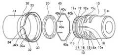
図1は本発明の一実施例にかかる管接続構造体を示す断面図である。図1において、管接続構造体は、自動車のエンジンのラジエータホースなどに使用されるものであり、筒状の雄部材10と、Oリング20と、パイプPの端部に形成された雌部材30と、係止部材40とを備え、Oリング20と係止部材40が雄部材10に装着されている。雄部材10に装着された係止部材40が雌部材30に係合することで雄部材10と雌部材30とを接続している。Next, in order to further clarify the configuration and operation of the present invention, preferred embodiments of the present invention will be described below.
(1) Schematic Configuration of Pipe Connection Structure FIG. 1 is a cross-sectional view showing a pipe connection structure according to one embodiment of the present invention. In FIG. 1, the pipe connection structure is used for a radiator hose or the like of an automobile engine, and has a
(2) 各部の構成
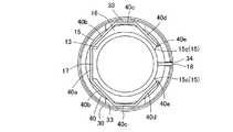
図2は管接続構造体の接続前の状態を説明する説明図、図3は管接続構造体の接続前の状態を示す斜視図である。なお、図2において、雄部材10が外観を示し、雌部材30が断面で示されている。雄部材10は、通路を形成するほぼ筒状の雄本体11を備えている。雄本体11の一端側の外周部には、ホースに挿入されるニップル11aが形成され、その他端側の外周部には、Oリング20を保持するOリング溝12および係止部材40を保持する保持部13が形成されている。Oリング溝12は、雄本体11の外周部から平行に突設した環状の突条12a,12aにより形成されている。また、保持部13は、雄本体11の外周部から突設した環状の突部14と、突部14と平行である突部15とを備え、その間に保持溝16を形成している。突部15は、一部を切り欠いて開口部15aとしたほぼC字形であり、開口部15aに面した両端が傾斜した係止面15c,15cになっている。図4は図2の4−4線に沿った断面図である。保持部13は、係止部材40を支持する部位であり、断面円形の一部から台座形状のベース部17(回り止め部)を備えている。図3において、雄本体11の外周部であって開口部15aには、雌部材30に係合する軸方向に沿ったストッパ18が突設されている。また、雄本体11の先端部は、保持部13から先端側に向けて縮径したテーパ面11bとなっている。(2) Configuration of Each Part FIG. 2 is an explanatory diagram for explaining a state before connection of the pipe connection structure, and FIG. 3 is a perspective view showing a state before connection of the pipe connection structure. In FIG. 2, the
図2において、雌部材30は、パイプPと一体の円筒状の雌本体31と、雌本体31から拡径された受入部32とを備えている。受入部32は、雄部材10のテーパ面11bと対向するフレア状に形成されており、開口32aの側から順に、縮径した挿入ガイド面32b、円筒状の支持部32c、縮径した傾斜部32d、円筒面32eを備えている。支持部32cには、180゜の間隔で2カ所の係合用開口33,33が貫通形成されている。これらの係合用開口33,33は、係止部材40の一部を挿入可能に形成されている。また、受入部32の開口32aには、図3に示すように軸方向に切欠き34が形成されている。この切欠き34は、雄部材10側のストッパ18を突入可能に形成され、雄部材10と雌部材30との回り止めをしている。 In FIG. 2, the
係止部材40は、雄部材10と雌部材30とを抜止するものであり、保持部13の外径より大きい8角形の形状(ほぼC字形)に鋼線を折曲形成することにより形成されている。すなわち、図4に示すように、係止部材40は、8角形のほぼ中央部の辺に形成されかつ保持部13のベース部17に支持される基部40aと、傾斜部40b,40b、係合部40c,40cと、傾斜部40d,40dと、開放端から軸方向に向けて突出したフック40e,40eとを備え、これらで8角形に形成されている。フック40e,40eは、指でもって図示の上下方向に拡開または縮径する力を加えることにより、弾性変形するように形成されている。フック40e,40eは、突部15の係止面15c,15cに押圧することにより係止部材40を保持部13に対して位置決めしている。 The locking
(3) 管接続構造体の接続作業
管接続構造体において、配管を行なうには、図5に示すように、Oリング20をOリング溝12に保持するとともに、係止部材40をその弾性力に抗して雄部材10の保持部13にそれぞれ保持させておき、さらにニップル11aにホースHを挿入しておく。このとき、係止部材40は、基部40aがベース部17(図4参照)で支持されるとともに、フック40e,40eが係止面15c,15cを押圧して、その弾性復元力によりその係合部40c,40cを突出させた状態で保持させる。そして、雄部材10の先端側を雌部材30の受入部32の開口32aから相対的に挿入する。これにより、図6に示すように、係止部材40の係合部40c,40cは、雌部材30の挿入ガイド面32bに案内されつつ弾性力に抗して縮径され、そして図7に示すように、係合用開口33,33に達したときに、係止部材40の弾性力が開放されることで係合用開口33,33に係合する。これにより、雄部材10は、雌部材30に対して係止部材40を介在させて、軸方向および半径方向で係止される。(3) Connection work of pipe connection structure In order to perform piping in the pipe connection structure, the O-
こうして配管の終了した管接続構造体では、図1に示すようにOリング20がOリング溝12と雌部材30の内壁面とで液密状態を確保し、雄部材10の通路および雌部材30の通路を介して流体が移送可能になる。このとき、雄部材10が雌部材30から抜け出る方向に引っ張られた場合や雄部材10と雌部材30との間に軸直角方向の外力が作用した場合であっても、雄部材10が雌部材30と係止部材40を介して強力に保持されているため、ある程度の引張り力や外力によっても雄部材10は、雌部材30内に安定して保持される。
そして、作業者が雄部材10を雌部材30から抜こうとするときには、係止部材40のフック40e,40eを指で摘むか、治具を用いて、フック40e,40eを互いに近づけ、係止部材40をその弾性力に抗して縮径する。これにより、係止部材40は、雌部材30の係合用開口33,33との係止が解かれ、作業者は雄部材10を雌部材30から相対的に抜くことができる。したがって、実施例にかかる管接続構造体は、素早く配管ができ、かつ配管における信頼性も高いものである。In the pipe connection structure in which the piping is thus completed, as shown in FIG. 1, the O-
When the operator tries to remove the
(4) 管接続構造体の作用・効果
(4)−1 管接続構造体によれば、配管の際に、係止部材40は、断面非円形の保持部13のベース部17で弾性変形を抑制されるように保持されて縮径および拡径するから、係止部材40を位置決めするための面倒な作業を必要とせず、作業性に優れている。
(4)−2 係止部材40の係合部40c,40cは、雌部材30の受入部32を貫通形成した係合用開口33,33に突入することで雌部材30と係合する構成であるから、従来の技術で説明したように、係止部材40が雌部材30との掛かり代を所定の範囲内にするために、雌部材の保持溝の深さなどに高い寸法精度を必要とせず、構成を簡単にできる。
(4)−3 雌部材30の係合用開口33,33は、受入部32の一部を貫通形成した構成であるから、スライド型を用いた射出成形方法や穴開け加工方法で簡単に製造することができ、生産性に優れている。(4) Action and effect of the pipe connection structure (4) -1 According to the pipe connection structure, the locking
(4) -2 The engaging
(4) -3 Since the engaging
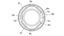
(5) この発明は上記実施例に限られるものではなく、その要旨を逸脱しない範囲において種々の態様において実施することが可能であり、例えば次のような変形も可能である。
(5)−1 保持部の回り止め部は、係止部材を位置決めできる構成であれば、特に限定されず、例えば、図8の雄部材10Bに示すように保持部13Bの一端から断面半円に突設したベース部17Bを形成して、ベース部17Bに係止部材40を支持するとともに、係止面15cで係止部材40のフック40e,40eで回り止めする構成や、係止部材の一部をU字形に折曲した基部を形成し、この基部に係合する凹所や突部でフックとともに回り止めする構成であってもよい。
(5)−2 上記実施例の係止部材は、断面8角形であるが、雄本体の外周面を囲む形状であれば特に限定されない。
(5)−3 上記実施例では、エンジンの冷却系の管接続構造体について説明したが、これに限らず、燃料系などの他の箇所に適用してもよい。この場合には、Oリングなどシール部材は、高温用と低温用の2つ用いることが好ましい。(5) The present invention is not limited to the above embodiment, and can be implemented in various modes without departing from the gist thereof. For example, the following modifications are possible.
(5) -1 The anti-rotation part of the holding part is not particularly limited as long as the locking member can be positioned. For example, as shown in the
(5) -2 The locking member of the above embodiment has an octagonal cross section, but is not particularly limited as long as it has a shape surrounding the outer peripheral surface of the male main body.
(5) -3 In the above embodiment, the pipe connection structure of the engine cooling system has been described. However, the present invention is not limited thereto, and may be applied to other locations such as a fuel system. In this case, it is preferable to use two sealing members such as an O-ring for high temperature and low temperature.
10...雄部材
11...雄本体
11a...ニップル
11b...テーパ面
12...Oリング溝
12a...突条
13...保持部
14...突部
15...突部
15a...開口部
15c...係止面
16...保持溝
17...ベース部
18...ストッパ
20...Oリング
30...雌部材
30a...通路
31...雌本体
32...受入部
32a...開口
32b...挿入ガイド面
32c...支持部
32d...傾斜部
32e...円筒面
33...係合用開口
34...切欠き
40...係止部材
40a...基部
40b...傾斜部
40c...係合部
40d...傾斜部
40e...フック
P...パイプ
H...ホースDESCRIPTION OF
Claims (3)
Translated fromJapanese上記雄部材(10)は、通路を形成する筒状の雄本体(11)と、該雄本体(11)の外周部に形成され上記係止部材(40)を回り止めした状態で保持する保持部(13)とを有し、上記保持部(13)は、上記雄本体(11)の外周部に環状に突設された突部(15)と、該突部(15)の一部を切り欠いた開口部(15a)と、該開口部(15a)に面しかつ上記突部(15)の両端に傾斜して形成された係止面(15c)と、上記雄部材(10)の外周部の一部を断面非円形としたベース部(17)とを有し、
上記係止部材(40)は、上記保持部(13)に保持され、弾性部材からC字形に形成されており、C字形のほぼ中央部に形成され上記ベース部(17)に倣った基部(40a)と、C字形の開放端を上記軸方向に折曲して形成したフック(40e)と、上記基部(40a)とフック(40e)との間に形成され上記雌部材(30)に係合する係合部(40c)とを有し、
上記雌部材(30)は、通路を形成する筒状の雌本体(31)と、該雌本体(31)の開口端部に形成され上記雄部材(10)を嵌合する受入部(32)と、該受入部(32)に貫通形成され上記雄部材(10)に保持された上記係止部材(40)の係合部(40c)を径方向に突入させる係合用開口(33)とを有し、
上記係止部材(40)の基部(40a)が上記ベース部(17)に位置決めされるとともに、上記フック(40e)が上記係止面(15c)を押圧することにより、上記係止部材(40)が上記雄部材(10)に対して回り止めされた状態にて上記保持部(13)に保持され、
上記係止部材(40)を保持した上記雄部材(10)を上記雌部材(30)に対して挿入することで、上記係止部材(40)が径方向に縮径または拡径して上記係合部(40c)が上記係合用開口(33)に突入して上記雌部材(30)に係合するように構成したこと、
を特徴とする管接続構造体。A male member (10) having a passage connected to the tubular body, a female member (30) having a passage connected to another tubular body, and between the male member (10) and the female member (30) A pipe connection structure comprising a locking member (40) interposed between the male member (10) and the female member (30) in theaxial direction ;
The male member (10) is a cylindrical male main body (11) that forms a passage, and aholding that is formed on the outer peripheral portion of the male main body (11) and thatstops the locking member (40).The holding portion (13) includes a protrusion (15) projecting annularly on the outer peripheral portion of the male body (11), and a part of the protrusion (15). A notched opening (15a), a locking surface (15c) that faces the opening (15a) and is inclined at both ends of the protrusion (15), and the male member (10). A base portion (17) having a non-circular cross section at a part of the outer periphery,
The locking member (40) is held by the holding portion (13), is formed in a C shape from an elastic member, and is formed ina substantially central portion of the C shape and is abase portion (following the base portion (17)). 40a), a hook (40e) formed by bending the C-shaped open end in the axial direction, and the base member (40a) and the hook (40e). Engaging part (40c)
The female member (30) includes a cylindrical female main body (31) that forms a passage, and a receiving portion (32) that is formed at the open end of the female main body (31) and that engages the male member (10). And an engagement opening (33) for penetrating the engagement portion (40c) of the locking member (40) formed through the receiving portion (32) and held by the male member (10) in the radial direction. Have
The base part (40a) of the locking member (40) is positioned on the base part (17), and the hook (40e) presses the locking surface (15c), whereby the locking member (40 ) Is held by the holding portion (13) in a state of being prevented from rotating with respect to the male member (10),
By inserting the male member (10) holding the locking member (40) into the female member (30), the locking member (40) is radially reduced or expanded in diameter. The engaging portion (40c) is configured to enter the engaging opening (33) and engage with the female member (30);
A pipe connection structure characterized by the above.
上記係合部(40c)は、上記基部(40a)が上記ベース部(17)で支持されている状態にて上記基部(40a)の両側を支点として径方向に縮径または拡径するように構成した管接続構造体。In the pipe connection structure according toclaim 1 ,
The engaging portion (40c) is radially reduced or expanded in diameter with the base portion (40a) being supported by the base portion (17) with both sides of the base portion (40a) as fulcrums. Constructed pipe connection structure.
上記係合部(40c)が上記基部(40a)と上記フック(40e)とを結ぶ方向とほぼ直角方向に拡径または縮径するように構成した管接続構造体。In the pipe connection structure according toclaim 2 ,
A pipe connection structure configured such that the engagement portion (40c) expands or contracts in a direction substantially perpendicular to a direction connecting the base portion (40a) and the hook (40e).
Priority Applications (2)
| Application Number | Priority Date | Filing Date | Title |
|---|---|---|---|
| JP2005215838AJP4644063B2 (en) | 2005-07-26 | 2005-07-26 | Pipe connection structure |
| US11/492,219US7393019B2 (en) | 2005-07-26 | 2006-07-25 | Tube connection assembly |
Applications Claiming Priority (1)
| Application Number | Priority Date | Filing Date | Title |
|---|---|---|---|
| JP2005215838AJP4644063B2 (en) | 2005-07-26 | 2005-07-26 | Pipe connection structure |
Publications (2)
| Publication Number | Publication Date |
|---|---|
| JP2007032673A JP2007032673A (en) | 2007-02-08 |
| JP4644063B2true JP4644063B2 (en) | 2011-03-02 |
Family
ID=37694955
Family Applications (1)
| Application Number | Title | Priority Date | Filing Date |
|---|---|---|---|
| JP2005215838AExpired - Fee RelatedJP4644063B2 (en) | 2005-07-26 | 2005-07-26 | Pipe connection structure |
Country Status (2)
| Country | Link |
|---|---|
| US (1) | US7393019B2 (en) |
| JP (1) | JP4644063B2 (en) |
Families Citing this family (56)
| Publication number | Priority date | Publication date | Assignee | Title |
|---|---|---|---|---|
| DE10346712B4 (en)* | 2003-10-08 | 2006-02-02 | Henn Gmbh & Co. Kg | Plug connection for pipe and hose lines with detent spring guide |
| DE10347929A1 (en)* | 2003-10-15 | 2005-05-19 | Henn Gmbh & Co. Kg | Connector for pipes and hoses has at least in region of locking spring openings a double walled construction, whereby double walls are squashed together at least in this region but spaced apart outside of it |
| DE102004016599B3 (en)* | 2004-04-03 | 2005-09-08 | Henn Gmbh & Co. Kg | Plug-in connection with rotation preventing stops for hoses and pipes has plug with guide grooves in end fitting into socket with inner and outer tubular housings |
| JP5190648B2 (en)* | 2006-03-31 | 2013-04-24 | 秀男 鈴木 | Joint mechanism |
| JP4864692B2 (en)* | 2006-12-27 | 2012-02-01 | 株式会社デンソー | Piping joint device and manufacturing method thereof |
| KR101318628B1 (en) | 2007-05-11 | 2013-10-16 | 한라비스테온공조 주식회사 | Assembly Structure of Condenser and Jumper Tube |
| US7862366B2 (en)* | 2008-10-14 | 2011-01-04 | Woodhead Industries, Inc. | Electrical connector with locking clip |
| US10711930B2 (en)* | 2009-12-09 | 2020-07-14 | Nordson Corporation | Releasable connection assembly |
| FR2954007B1 (en)* | 2009-12-11 | 2011-12-23 | Radiall Sa | CONNECTION ASSEMBLY |
| FR2954006B1 (en)* | 2009-12-11 | 2011-12-23 | Radiall Sa | CONNECTION ASSEMBLY. |
| US9168203B2 (en) | 2010-05-21 | 2015-10-27 | Carmel Pharma Ab | Connectors for fluid containers |
| ES2691425T3 (en)* | 2010-05-21 | 2018-11-27 | Carmel Pharma Ab | Connector, fluid container |
| KR101180871B1 (en) | 2010-06-07 | 2012-09-10 | 한일튜브 주식회사 | Connector for fluid line |
| US8568015B2 (en) | 2010-09-23 | 2013-10-29 | Willis Electric Co., Ltd. | Decorative light string for artificial lighted tree |
| US20120086201A1 (en)* | 2010-10-12 | 2012-04-12 | Joseph Stevenson Murken | Detachable hose coupling and staple remover |
| US8985200B2 (en) | 2010-12-17 | 2015-03-24 | Halliburton Energy Services, Inc. | Sensing shock during well perforating |
| AU2010365401B2 (en) | 2010-12-17 | 2015-04-09 | Halliburton Energy Services, Inc. | Well perforating with determination of well characteristics |
| US8298633B1 (en) | 2011-05-20 | 2012-10-30 | Willis Electric Co., Ltd. | Multi-positional, locking artificial tree trunk |
| US9091152B2 (en) | 2011-08-31 | 2015-07-28 | Halliburton Energy Services, Inc. | Perforating gun with internal shock mitigation |
| US8662540B2 (en) | 2011-11-02 | 2014-03-04 | Philip C. Whitener | Quick tube connector |
| US9157587B2 (en) | 2011-11-14 | 2015-10-13 | Willis Electric Co., Ltd. | Conformal power adapter for lighted artificial tree |
| US8569960B2 (en) | 2011-11-14 | 2013-10-29 | Willis Electric Co., Ltd | Conformal power adapter for lighted artificial tree |
| EP2597348A1 (en)* | 2011-11-24 | 2013-05-29 | Eaton Germany GmbH | Plug-in connection with a retaining clip |
| US8876321B2 (en) | 2011-12-09 | 2014-11-04 | Willis Electric Co., Ltd. | Modular lighted artificial tree |
| US9179793B2 (en) | 2012-05-08 | 2015-11-10 | Willis Electric Co., Ltd. | Modular tree with rotation-lock electrical connectors |
| US9044056B2 (en) | 2012-05-08 | 2015-06-02 | Willis Electric Co., Ltd. | Modular tree with electrical connector |
| US10206530B2 (en) | 2012-05-08 | 2019-02-19 | Willis Electric Co., Ltd. | Modular tree with locking trunk |
| US9572446B2 (en) | 2012-05-08 | 2017-02-21 | Willis Electric Co., Ltd. | Modular tree with locking trunk and locking electrical connectors |
| DE102012104288A1 (en)* | 2012-05-16 | 2013-11-21 | Voss Automotive Gmbh | "Connector for fluid lines and holding part for such a connector" |
| US9016385B2 (en)* | 2013-02-20 | 2015-04-28 | Halliburton Energy Services, Inc. | Securing connections in alternate path well screens |
| AU2013378819B2 (en)* | 2013-02-20 | 2016-12-15 | Halliburton Energy Services, Inc. | Securing connections in alternate path well screens |
| US9671074B2 (en) | 2013-03-13 | 2017-06-06 | Willis Electric Co., Ltd. | Modular tree with trunk connectors |
| US9439528B2 (en) | 2013-03-13 | 2016-09-13 | Willis Electric Co., Ltd. | Modular tree with locking trunk and locking electrical connectors |
| JP6063309B2 (en)* | 2013-03-18 | 2017-01-18 | 株式会社タブチ | Fusion saddle water tap |
| US9649484B2 (en)* | 2013-03-28 | 2017-05-16 | Covidien Lp | Snap connection for two tubes |
| DE202013103217U1 (en)* | 2013-07-18 | 2013-08-26 | HARTING Electronics GmbH | Lock for connectors |
| US9894949B1 (en) | 2013-11-27 | 2018-02-20 | Willis Electric Co., Ltd. | Lighted artificial tree with improved electrical connections |
| US8870404B1 (en) | 2013-12-03 | 2014-10-28 | Willis Electric Co., Ltd. | Dual-voltage lighted artificial tree |
| US9839238B2 (en)* | 2014-02-28 | 2017-12-12 | Rai Strategic Holdings, Inc. | Control body for an electronic smoking article |
| US20150267657A1 (en)* | 2014-03-24 | 2015-09-24 | Caterpillar Inc. | Quick Twist Disconnect Device and System |
| US9883566B1 (en) | 2014-05-01 | 2018-01-30 | Willis Electric Co., Ltd. | Control of modular lighted artificial trees |
| AT516151B1 (en)* | 2015-03-03 | 2016-03-15 | Henn Gmbh & Co Kg | Connector assembly for connecting cables |
| US9689147B2 (en)* | 2015-07-13 | 2017-06-27 | Delta Faucet Company | Snap in mounting shank for a faucet |
| DE102015111895A1 (en)* | 2015-07-22 | 2017-01-26 | Dr. Ing. H.C. F. Porsche Aktiengesellschaft | Vehicle component and motor vehicle |
| CN105155632B (en)* | 2015-10-10 | 2017-02-01 | 厦门建霖工业有限公司 | Method and faucet structure for rapidly disassembling and replacing faucet main body |
| EP3452747B1 (en)* | 2016-05-02 | 2020-10-14 | Nobel Gemlik Otomotiv San. Ve Tic. A.S. | Fuel filling line - fuel tank quick connection apparatus |
| GB2543118B (en)* | 2016-05-03 | 2017-11-15 | Tech Solutions (Uk) Ltd | Mounting system |
| JP6563854B2 (en)* | 2016-05-20 | 2019-08-21 | 株式会社ニフコ | Locking mechanism of tubular body |
| USD838366S1 (en) | 2016-10-31 | 2019-01-15 | Nordson Corporation | Blood pressure connector |
| CN107465033B (en)* | 2017-08-22 | 2019-05-28 | 安徽江淮汽车集团股份有限公司 | A kind of assembling structure of male end plug-in jacket and female end plug-in jacket |
| USD859618S1 (en) | 2017-09-15 | 2019-09-10 | Pentair Water Pool And Spa, Inc. | Heating apparatus clip |
| US10683974B1 (en) | 2017-12-11 | 2020-06-16 | Willis Electric Co., Ltd. | Decorative lighting control |
| US11137094B2 (en)* | 2018-04-23 | 2021-10-05 | Reliance World Wide Corporation | Clip end device |
| US11578827B2 (en) | 2019-10-21 | 2023-02-14 | The Reliable Automatic Sprinkler Co. Inc. | Fire protection sprinkler with a push-in connection |
| US20220331631A1 (en)* | 2021-04-19 | 2022-10-20 | The Reliable Automatic Sprinkler Co. Inc. | Fire protection sprinkler with a push-in connection |
| US11821558B2 (en)* | 2021-09-08 | 2023-11-21 | Cooper-Standard Automotive Inc. | Fluid connector with dry break |
Family Cites Families (18)
| Publication number | Priority date | Publication date | Assignee | Title |
|---|---|---|---|---|
| US472342A (en)* | 1892-04-05 | X h hosexcouplingl | ||
| GB957860A (en)* | 1962-12-31 | 1964-05-13 | Superflexit | Means for locking components against relative rotation |
| US3428340A (en)* | 1967-03-20 | 1969-02-18 | Harry L Pelton | Hose coupling |
| US3773360A (en)* | 1972-09-01 | 1973-11-20 | W Timbers | Quick disconnect coupling |
| US4007953A (en)* | 1975-09-10 | 1977-02-15 | International Telephone And Telegraph Corporation | Removable captive coupling nut assembly |
| US4804206A (en)* | 1987-10-13 | 1989-02-14 | Dover Corporation | Swivel construction and method of making the same |
| JPH0477090U (en)* | 1990-11-16 | 1992-07-06 | ||
| JPH0650482A (en) | 1992-05-29 | 1994-02-22 | Tokai Rubber Ind Ltd | Hose connecting structure |
| US5226682A (en)* | 1992-07-21 | 1993-07-13 | Aeroquip Corporation | Coupling assembly |
| US5876071A (en)* | 1995-07-28 | 1999-03-02 | Aldridge; James H. | Quick connect/disconnect connector and method for use |
| JP2000504092A (en)* | 1996-01-29 | 2000-04-04 | ノーマン、エス.スローン | Splined safety lock with elastic retaining ring |
| US6485290B2 (en)* | 1999-08-10 | 2002-11-26 | The Coleman Company, Inc. | Portable lantern |
| DE19957946B4 (en)* | 1999-12-02 | 2005-07-14 | Behr Gmbh & Co. Kg | Connecting piece for a heat exchanger |
| FR2802276B1 (en)* | 1999-12-13 | 2002-06-07 | Nobel Plastiques | LOW PERMEABILITY CONNECTION DEVICE |
| FR2820489B1 (en)* | 2001-02-05 | 2004-01-23 | Valeo | SUPPLY CONNECTION DEVICE FOR A FLUID PRESSURE SYSTEM |
| US6554322B2 (en)* | 2001-05-21 | 2003-04-29 | Thach Duong | Controller valve coupling |
| JP4354794B2 (en)* | 2002-12-18 | 2009-10-28 | 株式会社パイオラックス | Connector with checker |
| JP4529658B2 (en)* | 2003-11-28 | 2010-08-25 | 東海ゴム工業株式会社 | Quick connector |
- 2005
- 2005-07-26JPJP2005215838Apatent/JP4644063B2/ennot_activeExpired - Fee Related
- 2006
- 2006-07-25USUS11/492,219patent/US7393019B2/ennot_activeExpired - Fee Related
Also Published As
| Publication number | Publication date |
|---|---|
| JP2007032673A (en) | 2007-02-08 |
| US20070026703A1 (en) | 2007-02-01 |
| US7393019B2 (en) | 2008-07-01 |
Similar Documents
| Publication | Publication Date | Title |
|---|---|---|
| JP4644063B2 (en) | Pipe connection structure | |
| JP4759421B2 (en) | Quick connector | |
| JP5687152B2 (en) | Piping joint | |
| JP4329063B2 (en) | Pipe fitting | |
| JP5715700B2 (en) | connector | |
| JP4174738B2 (en) | Hose fittings | |
| EP2871398B1 (en) | Connector | |
| JP2007255669A (en) | Quick connector | |
| JP2004144173A (en) | Pipe fittings | |
| US7328922B2 (en) | Quick connector | |
| KR20040058081A (en) | Joint for piping | |
| JP6131120B2 (en) | connector | |
| JP4402737B1 (en) | Pipe fitting | |
| JP5941772B2 (en) | connector | |
| JP2017187132A (en) | Hose clip | |
| JP4444878B2 (en) | Piping joint | |
| JP4216672B2 (en) | Stop ring and fluid equipment with stop ring | |
| CN108174609A (en) | "Quick Fit Connectors for Pneumatic Systems" | |
| JP2010096230A (en) | Pipe joint | |
| JP4803537B2 (en) | Pipe fitting | |
| JPS6110077Y2 (en) | ||
| JP5098101B2 (en) | Pipe fitting | |
| JP5826014B2 (en) | Pipe connection structure | |
| JP6989167B1 (en) | Snap-fit engagement connector | |
| JP5896831B2 (en) | Piping connector |
Legal Events
| Date | Code | Title | Description |
|---|---|---|---|
| A621 | Written request for application examination | Free format text:JAPANESE INTERMEDIATE CODE: A621 Effective date:20070919 | |
| A711 | Notification of change in applicant | Free format text:JAPANESE INTERMEDIATE CODE: A711 Effective date:20071214 | |
| A521 | Request for written amendment filed | Free format text:JAPANESE INTERMEDIATE CODE: A821 Effective date:20071214 | |
| A977 | Report on retrieval | Free format text:JAPANESE INTERMEDIATE CODE: A971007 Effective date:20100217 | |
| A131 | Notification of reasons for refusal | Free format text:JAPANESE INTERMEDIATE CODE: A131 Effective date:20100608 | |
| A521 | Request for written amendment filed | Free format text:JAPANESE INTERMEDIATE CODE: A523 Effective date:20100804 | |
| TRDD | Decision of grant or rejection written | ||
| A01 | Written decision to grant a patent or to grant a registration (utility model) | Free format text:JAPANESE INTERMEDIATE CODE: A01 Effective date:20101124 | |
| A01 | Written decision to grant a patent or to grant a registration (utility model) | Free format text:JAPANESE INTERMEDIATE CODE: A01 | |
| A61 | First payment of annual fees (during grant procedure) | Free format text:JAPANESE INTERMEDIATE CODE: A61 Effective date:20101203 | |
| R150 | Certificate of patent or registration of utility model | Ref document number:4644063 Country of ref document:JP Free format text:JAPANESE INTERMEDIATE CODE: R150 Free format text:JAPANESE INTERMEDIATE CODE: R150 | |
| FPAY | Renewal fee payment (event date is renewal date of database) | Free format text:PAYMENT UNTIL: 20131210 Year of fee payment:3 | |
| R250 | Receipt of annual fees | Free format text:JAPANESE INTERMEDIATE CODE: R250 | |
| R250 | Receipt of annual fees | Free format text:JAPANESE INTERMEDIATE CODE: R250 | |
| LAPS | Cancellation because of no payment of annual fees |