JP4643699B2 - A numerical control device having a function of editing a plurality of programs. - Google Patents
A numerical control device having a function of editing a plurality of programs.Download PDFInfo
- Publication number
- JP4643699B2 JP4643699B2JP2008261240AJP2008261240AJP4643699B2JP 4643699 B2JP4643699 B2JP 4643699B2JP 2008261240 AJP2008261240 AJP 2008261240AJP 2008261240 AJP2008261240 AJP 2008261240AJP 4643699 B2JP4643699 B2JP 4643699B2
- Authority
- JP
- Japan
- Prior art keywords
- program
- cursor
- time
- block
- displayed
- Prior art date
- Legal status (The legal status is an assumption and is not a legal conclusion. Google has not performed a legal analysis and makes no representation as to the accuracy of the status listed.)
- Active
Links
Images


Landscapes
- Numerical Control (AREA)
Description
Translated fromJapanese本発明は、多系統制御機能を有する数値制御装置に関し、各系統のプログラムを並列に表示して編集可能にした数値制御装置に関する。 The present invention relates to a numerical control device having a multi-system control function, and more particularly to a numerical control device that displays a program of each system in parallel for editing.
複数の系統を制御可能な数値制御装置においては、各系統毎のプログラムをそれぞれ実行し、系統間で同期をとりながら工作機械等の機械を運転することで、複数の加工工程を同時にもしくは連続的に行うことができる。この多系統制御が可能な数値制御装置において、各系統で選択されている加工プログラムを編集する場合、従来は、編集目的の系統を切り換え、同期条件などを目視にて確認し、個別に編集を行っている。 In a numerical control device that can control multiple systems, a plurality of machining processes can be performed simultaneously or continuously by executing a program for each system and operating a machine such as a machine tool while synchronizing the systems. Can be done. In this numerical control device capable of multi-system control, when editing the machining program selected for each system, conventionally, the editing target system is switched, the synchronization conditions etc. are visually checked, and the editing is performed individually. Is going.
この各系統のプログラムを表示装置に表示する方法として、各系統のプログラムを並列に表示する方法、直列に表示する方法が知られている。並列に表示する場合、時間の関係を認識できるように、時間を対応させて各系統のプログラムを並列に表示することや、1つの加工プログラム中に多系統制御と単独制御を混在させて、直列に表示する方法も知られている(特許文献1参照)。 As a method of displaying the programs of each system on a display device, a method of displaying the programs of each system in parallel and a method of displaying in series are known. When displaying in parallel, the program of each system is displayed in parallel with the corresponding time so that the relationship of time can be recognized, or multi-system control and single control are mixed in one machining program, There is also known a display method (see Patent Document 1).
各系統のプログラムを編集する場合、各系統でのプログラム指令により複数の系統で制御される軸を互いに協調しながら同時に移動させるものであることから、各系統でのプログラム指令の実行順序を把握し、系統間での同期、実行、待ち合わせの関係を確認しながら編集する必要がある。しかしながら、各系統のプログラムを直列に表示する方法では、系統間における時間の関係を認識することが難しく、その編集が困難である。一方、各系統のプログラムを並列に表示したとしても、単に並列に表示するだけでは、系統間での複雑な同期、実行、待ち合わせの関係等の時間の関係を認識することは難しい。そのため、前記特許文献1に記載されているように、各系統のプログラムを並列に表示し、待ち合わせコード等を対応させて時間の関係を理解し易いように表示する方法が提案されているが、この方法では、空白が多くなり、表示できるプログラム部分が少なくなり、編集作業が困難となるという欠点を有する。 When editing a program of each system, the axes controlled by multiple systems are moved simultaneously in cooperation with each other according to the program commands in each system, so the execution order of the program commands in each system is known. It is necessary to edit while checking the relationship between synchronization, execution, and waiting between systems. However, in the method of displaying the programs of each system in series, it is difficult to recognize the time relationship between the systems, and editing is difficult. On the other hand, even if the programs of each system are displayed in parallel, it is difficult to recognize time relationships such as complicated synchronization, execution, and waiting relationships between systems only by displaying them in parallel. Therefore, as described in
そこで、本発明の目的は、各系統のプログラムを同一画面上に同時に並列に表示し、同期関係を簡単に認識できると共に、空白がなく各プログラムを表示できる数値制御装置を提供することにある。 SUMMARY OF THE INVENTION An object of the present invention is to provide a numerical control device that can display programs of each system simultaneously in parallel on the same screen, easily recognize the synchronization relationship, and display each program without blanks.
請求項1に係る発明は、多系統制御機能を有し、複数系統のプログラムを並列に表示してプログラムの編集ができる編集機能を備えた数値制御装置であって、同期関係を見るための設定運転経過時間が初期設定される記憶手段と、少なくとも2つ以上の系統のプログラムを同一画面上に並列に表示した状態で、カーソル操作手段の操作により、編集対象のプログラム内で編集箇所を指し示すカーソルをプログラムに対して相対移動させるとき、該カーソルと連動して他の系統のプログラム内のカーソルを同一行ラインに揃えてプログラムに対して相対移動させるカーソル移動制御手段と、カーソルが示す各系統のプログラムのブロックの指令を実行するのに要する運転時間を各系統毎に算出する手段と、各系統毎に求められた前記運転時間を積算する積算手段と、前記積算手段で積算された積算時間が前記記憶手段に記憶された時間と一致または超える時のブロックかを判別する判別手段と、前記判別手段により、積算時間が、前記記憶手段に記憶された時間と一致または超えると判別されたときの系統に対して前記カーソルのプログラムに対する相対移動を停止させる手段と、表示した全ての系統のプログラムのカーソルに対する相対移動が停止すると、前記記憶手段に記憶する時間に設定運転経過時間を加算する手段と、表示した全ての系統のプログラムのカーソルに対する相対移動が停止し、前記記憶手段に記憶する時間に設定運転経過時間が加算された後、再度の前記カーソル操作手段の操作により、カーソル移動制御手段によってカーソルのプログラムに対する相対移動を行わせる手段とを備え、カーソル操作により、設定運転経過時間毎に、その運転経過時間で各系統のプログラムで実行されるブロックを同一行ラインに表示可能にしたことを特徴とするものである。The invention according to
請求項2に係る発明は、同期関係を見るための設定運転経過時間が初期設定される記憶手段と、少なくとも2つ以上の系統のプログラムを同一画面上に並列に表示した状態で、カーソル操作手段の操作により、編集対象のプログラム内で編集箇所を指し示すカーソルを移動させるとき、該カーソルと連動して他の系統のプログラム内のカーソルを同一行ラインに揃えて移動させるカーソル移動制御手段と、カーソルが示す各系統のプログラムのブロックの指令を実行するのに要する運転時間を各系統毎に算出する手段と、各系統毎に求められた前記運転時間を積算する積算手段と、前記積算手段で積算された積算時間が前記記憶手段に記憶された時間と一致または超える時のブロックかを判別する判別手段と、前記判別手段により、いずれかの系統の積算時間が、前記記憶手段に記憶された時間と一致または超えると判別されたときカーソル移動制御手段を無効にして前記カーソルの移動を停止させる手段と、カーソルの移動が停止された後、前記カーソル操作手段の操作により、積算時間が前記記憶手段に記憶された時間に達していない系統のプログラムをスクロールする手段と、前記判別手段で、積算時間が前記記憶手段に記憶された時間に達するブロックがカーソル位置に達したと判別されたとき前記スクロールを停止させる手段と、スクロールしていた全てのプログラムのスクロールが停止した後、前記記憶手段に記憶する時間に設定運転経過時間を加算する手段と、スクロールしていた全てのプログラムのスクロールが停止した後、前記カーソル移動制御手段を有効にしてカーソル移動を可能にする手段とを備え、カーソル操作により、設定運転経過時間毎に、その運転経過時間で各系統のプログラムで実行されるブロックを同一行ラインに表示可能にしたものである。 According to a second aspect of the present invention, there is provided storage means for initially setting a set operation elapsed time for viewing a synchronous relationship, and cursor operation means in a state where at least two or more systems of programs are displayed in parallel on the same screen. Cursor movement control means for moving the cursor in the program of another system in alignment with the cursor to move the cursor in the same line line in conjunction with the cursor when moving the cursor indicating the editing location in the program to be edited Means for calculating for each system the operation time required to execute the program block command of each system, integrating means for integrating the operation time obtained for each system, and integrating by the integrating means A discriminating means for discriminating whether the accumulated time is equal to or exceeding the time stored in the storage means; When it is determined that the accumulated time of the system matches or exceeds the time stored in the storage means, the means for disabling the cursor movement control means and stopping the movement of the cursor, and after the movement of the cursor is stopped, By the operation of the cursor operating means, means for scrolling a program of a system whose accumulated time has not reached the time stored in the storage means, and the accumulated time reaches the time stored in the storage means by the determining means. Means for stopping the scrolling when it is determined that the block has reached the cursor position, and means for adding the set operation elapsed time to the time stored in the storage means after the scrolling of all the scrolled programs is stopped After the scrolling of all the scrolled programs is stopped, the cursor movement control means is enabled. And means for allowing cursor movement, the cursor operation, each set operation elapsed time, the block to be executed by programs of each path in the operation elapsed time is obtained by allowing the display on the same row.
請求項3に係る発明は、同期関係を見るための設定運転経過時間が初期設定される記憶手段と、少なくとも2つ以上の系統のプログラムを同一画面上に並列に表示した状態で、カーソル操作手段の操作により、編集対象のプログラム内で編集箇所を指し示すカーソルを移動させるとき、該カーソルと連動して他の系統のプログラム内のカーソルを同一行ラインに揃えて移動させるカーソル移動制御手段と、プログラムのブロックの指令を実行するのに要する運転時間を各系統毎に算出する手段と、各系統毎に求められた前記運転時間を各プログラムの先頭より積算する積算手段と、前記積算手段で積算された積算時間が前記記憶手段に記憶された時間と一致または超える時のブロックかを判別する判別手段と、前記判別手段により、いずれかの系統の積算時間が、前記記憶手段に記憶された時間と一致または超えると判別されたときカーソル移動制御手段を無効にして前記カーソルの移動を停止させる手段と、カーソルの移動が停止した後、前記積算時間が前記記憶手段に記憶された時間と一致または超えない系統のプログラムに対して、前記運転時間を算出する手段及び積算手段で求められる積算時間が前記記憶手段に記憶された時間に達するブロックを検索する手段と、該検索する手段で、ブロックが求められると該ブロックをカーソル位置に位置するようにプログラムをシフトする手段と、プログラムのシフトが完了すると、前記記憶手段に記憶する時間に設定運転経過時間を加算する手段と、プログラムのシフトが完了すると、前記カーソル移動制御手段を有効にしてカーソル移動を可能にする手段とを備え、カーソル操作により、設定運転経過時間毎に、その運転経過時間で各系統のプログラムで実行されるブロックを同一行ラインに表示可能にしたものである。 According to a third aspect of the present invention, there is provided storage means for initially setting a set operation elapsed time for viewing a synchronous relationship, and cursor operation means in a state where at least two or more systems of programs are displayed in parallel on the same screen. Cursor movement control means for moving the cursor in the program of another system in alignment with the cursor and moving the cursor in the same line line in conjunction with the cursor when moving the cursor indicating the editing location in the program to be edited The operation time required to execute the block command is calculated for each system, the operation time obtained for each system is integrated from the head of each program, and the integration means A determining means for determining whether the accumulated time is equal to or exceeding the time stored in the storage means, and the determining means When it is determined that the accumulated time of the system matches or exceeds the time stored in the storage means, the means for disabling the cursor movement control means and stopping the movement of the cursor, and after the movement of the cursor is stopped, A block that reaches the time stored in the storage means and the integration time calculated by the means for calculating the operation time and the integration time for the program of the system whose integration time does not match or exceed the time stored in the storage means And a means for shifting the program so that the block is positioned at the cursor position when the block is obtained by the searching means, and a time stored in the storage means when the program shift is completed. The means for adding the elapsed driving time and the cursor movement control means are enabled when the program shift is completed to And means for enabling Le moved by cursor operation, each set operation elapsed time, the block to be executed by programs of each path in the operation elapsed time is obtained by allowing the display on the same row.
系統間で同時に動作する指令の把握および実行順序や待ち合わせ位置などの確認が正確にかつ迅速に行うことができ、多系統のプログラム編集の効率化と作業時間の短縮を図ることができる。 It is possible to ascertain the commands operating simultaneously between the systems and to confirm the execution order and the waiting position accurately and quickly, and to improve the efficiency of multi-system program editing and shorten the work time.
以下、本発明の実施形態を図面と共に説明する。
図1は、本発明の実施形態の数値制御装置の概要図である。数値制御装置のハードウェア構成は、従来の多系統制御機能を有する数値制御装置の構成と同じであり、図1ではこの数値制御装置のハードウェア構成の概要を簡単に記載している。従来の数値制御装置と相違する点は、各系統のプログラムを表示して、編集するときに、同期すべき又は同期するプログラムのブロック位置を容易に認識可能に表示される機能を備えている点で従来と相違するものであり、該機能を実行するソフトウェアが数値制御装置のメモリに格納されている点が相違するものである。Hereinafter, embodiments of the present invention will be described with reference to the drawings.
FIG. 1 is a schematic diagram of a numerical controller according to an embodiment of the present invention. The hardware configuration of the numerical control device is the same as the configuration of the conventional numerical control device having a multi-system control function, and FIG. 1 simply describes the outline of the hardware configuration of the numerical control device. The difference from the conventional numerical control device is that it has a function to display the program of each system and edit it so that the block position of the program to be synchronized or synchronized should be easily recognizable. However, it is different from the prior art in that the software for executing the function is stored in the memory of the numerical controller.
数値制御装置10は、プロセッサ11とバス16で接続された、ROM、RAM、不揮発性RAM等のメモリ12、CRTや液晶で構成された表示装置13、キーボード等のデータや指令を入力する入力手段14、各系統の可動軸を駆動するモータを制御する第1〜第n系統軸制御部15−1〜15−nを備えている。
メモリ12には、各系統のプログラムが格納されているとともに、プログラムの編集処理のソフトウェアが格納されており、特に、本発明に関係した後述する同期位置合わせモードの処理を実行するソフトウェアが格納されている。The
The memory 12 stores a program for each system and software for editing the program. In particular, software for executing processing in a synchronous alignment mode (to be described later) related to the present invention is stored. ing.
系統軸制御部15−1〜15−nは、プロセッサ11が各系統のプログラムを実行して分配される移動指令と、モータに設けられた位置・速度検出器からのフィードバック信号に基づいて、位置、速度のフィードバック制御を行い、さらには電流フィードバックを行って、各系統のモータを制御し、各系統の各軸を互いに協調しながら同時に同期、又は独立して移動させるものである。
この数値制御装置10による多系統の駆動制御動作は従来の多系統制御機能を有する数値制御装置と同一の動作であり変わりはない。
本発明は、多系統の各プログラムを編集するとき、同期位置合わせモードが設けられ、同期位置合わせができるようにした点において従来と相違するものである。The system axis control units 15-1 to 15-n are arranged based on a movement command distributed by the processor 11 executing a program of each system and a feedback signal from a position / speed detector provided in the motor. In addition, speed feedback control is performed, and further current feedback is performed to control the motors of the respective systems, and the respective axes of the respective systems are simultaneously synchronized or independently moved while cooperating with each other.
The multi-system drive control operation by the
The present invention is different from the prior art in that a synchronization alignment mode is provided to enable synchronization alignment when editing multiple programs.
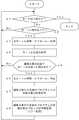
図2は、本実施形態の第1の態様(参考例)の同期位置合わせモードによる同期位置合わせ処理のアルゴリズムを示すフローチャートである。図3及び図4は、この第1の態様(参考例)の同期位置合わせモードによる位置合わせ処理における表示装置13の表示画面の説明図である。図3及び図4において、符号20で示す枠内が表示画面上の表示範囲を示す。又、符号21はカーソルを示す。
この第1の態様(参考例)は、同期位置合わせを行う同期対象のブロック情報としてシーケンス番号を用い、予め同期させるシーケンス番号をパラメータ等で設定しておく(図3及び図4に示す例では、「N333」「N444」が同期位置合わせを行うブロックのシーケンス番号として設定されているものとしている)。各プログラムの並列表示において、この設定した同期対象のシーケンス番号のブロックを同一行ライン上に揃えて表示し、同期関係を容易に認識できるようにしたものである。FIG. 2 is a flowchart showing the algorithm of the synchronization alignment process in the synchronization alignment mode according to the first aspect (reference example) of the present embodiment. 3 and 4 are explanatory diagrams of a display screen of the display device 13 in the alignment process in the synchronous alignment mode of the first mode (reference example). 3 and 4, the frame indicated by
In this first mode (reference example), a sequence number is used as synchronization target block information for synchronization alignment, and the sequence number to be synchronized is set in advance using parameters or the like (in the examples shown in FIGS. 3 and 4). , “N333” and “N444” are set as the sequence numbers of the blocks to be synchronized.) In the parallel display of each program, blocks with the set sequence numbers to be synchronized are displayed on the same line so that the synchronization relationship can be easily recognized.
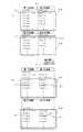
プログラムの編集を行う際に、同時に表示する系統を選択し、各系統のプログラムの同時表示操作を入力手段14より入力すると、選択された系統のプログラムが表示装置13の表示画面に並列に同時表示される。図3の例では、第1〜第3の系統が選択され、第1〜第3の系統のプログラムが横方向に並列表示された例を示している。図4の例では、第1〜第4の系統が選択され、第1〜第4の系統のプログラムが横方向と縦方向に並列表示された例を示している。こうして、選択系統のプログラムが並列表示され、編集がなされているときに、モード切り換え操作を行い、同期位置合わせモードに切り換えると、図2に示す処理をプロセッサ11は実行する。また、図3及び図4にて、図2に示す処理は同一である。更に、図3に対し図4は表示装置13の表示画面上に表示するプログラムの配置のみを変更したものであり、図4の図2に示す処理は省略する。 When editing the program, the system to be displayed at the same time is selected, and when the simultaneous display operation of the program of each system is input from the input means 14, the program of the selected system is simultaneously displayed in parallel on the display screen of the display device 13. Is done. The example of FIG. 3 shows an example in which the first to third systems are selected and the programs of the first to third systems are displayed in parallel in the horizontal direction. In the example of FIG. 4, the first to fourth systems are selected, and the programs of the first to fourth systems are displayed in parallel in the horizontal direction and the vertical direction. In this way, when the program of the selected system is displayed in parallel and edited, when the mode switching operation is performed to switch to the synchronous alignment mode, the processor 11 executes the processing shown in FIG. 3 and 4, the process shown in FIG. 2 is the same. Further, FIG. 4 is different from FIG. 3 in that only the arrangement of programs displayed on the display screen of the display device 13 is changed, and the processing shown in FIG. 2 of FIG. 4 is omitted.
まず、この同期位置合わせモードから他のモードへの切り換え操作がなされたか(ステップa1)、及び入力手段14に設けられたカーソル操作手段によりカーソル操作がなされたか(カーソルを下方へ移動させる操作)を繰り返し判断し(ステップa2)、編集箇所を示すカーソル操作がなされると、表示されている全系統のカーソル21をプログラムに対して相対移動させる(ステップa3)。この場合、編集対象のプログラムのカーソルと連動して、他の系統のカーソル21を同一行ライン上に揃え移動させる。図3において、図3(a)に示す位置にカーソル21があった状態で、カーソル操作がなされると、編集対象のプログラムの編集箇所を示すカーソル21とともに他の系統のカーソルも図3(b)に示すように連動して移動する。又、カーソル21が表示範囲の最下位に達したときは、プログラムがスクロールして上方に移動することによって、相対的にカーソル21が移動する。又、入力手段14内の次ページキーを操作すると、カーソル21は、次の行に移動し、かつ、そのカーソル21が位置する行を表示範囲の先頭行にしたプログラム表示に変更される。なお、モード切り換え操作がなされると、この同期位置合わせ処理は終了する。 First, whether the switching operation from the synchronous alignment mode to another mode has been performed (step a1), and whether the cursor operation has been performed by the cursor operation means provided in the input means 14 (operation to move the cursor downward). When it is repeatedly determined (step a2) and the cursor operation indicating the editing portion is performed, the displayed
次に、各系統のプログラム上におけるカーソル21の位置を取得し(ステップa4)、各系統のプログラム上のカーソル21が位置するブロックのシーケンス番号が設定されている同期対象のシーケンス番号か判断する。いずれの系統のプログラムにおいても、カーソル位置が同期対象のシーケンス番号のブロックではない場合はステップa1に戻りステップa1〜a5の処理を繰り返し実行する。いずれかの系統において、カーソル21が同期対象のシーケンス番号のブロックの位置にあれば、全系統のカーソル21の移動を停止する(ステップa6)。図3(b)では、第1の系統のプログラムにおいて、カーソル21が設定されている同期対象のシーケンス番号の「N333」の位置にあることから、全てのカーソルは、この位置でその移動を停止する。 Next, the position of the
次に、プロセッサ11は、表示された全系統のプログラムにおいて、カーソル位置が同期対象のシーケンス番号のブロック上にあるか判断し(ステップa7)、全てのプログラムにおいて、カーソル21が同期対象のシーケンス番号のブロック上になければ、モード切り換え操作がなされたか(ステップa8)、カーソル操作がなされたかを判断し(ステップa9)、カーソル操作ががなされると(カーソルを下方へ移動させる操作)、カーソル位置が同期対象のシーケンス番号のブロック上にないプログラムのみがスクロールされ、プログラム表示が1行ずつ上方に移動する(ステップa10)。そして、スクロールされたプログラム上でのカーソル21の位置を取得し(ステップa11)、その位置が同期対象のシーケンス番号のブロック位置か判断し(ステップa12)、同期対象のシーケンス番号のブロック位置ではない場合には、ステップa8に戻り、ステップa8〜a12の処理を繰り返し実行する。 Next, the processor 11 determines whether the cursor position is on the block of the sequence number to be synchronized in the displayed programs of all systems (step a7), and the
そして、スクロールされたプログラム上でのカーソル21の位置が同期対象のシーケンス番号のブロック位置であると判断されたときには、そのカーソルが同期位置にあるプログラムのスクロールを停止し(ステップa13)、ステップa7に戻る。以下、ステップa7以下の処理を実行し、表示された全てのプログラムにおいて、カーソル位置が同期対象のシーケンス番号のブロック上に達したとステップa7で判別されると、ステップa1に戻る。このようにして、各プログラムにおける同期対象のシーケンス番号のブロック上にカーソルが位置づけられ、同一行ライン上に揃って表示されることになり、各プログラム上における同期関係が明瞭となる。
図3(c)及び図4(c)は、同期対象のシーケンス番号「N333」のブロックが同一行ライン上のカーソル位置に揃って表示されている例を示している。When it is determined that the position of the
FIGS. 3C and 4C show an example in which the block with the sequence number “N333” to be synchronized is displayed aligned at the cursor position on the same row line.
次にカーソル操作がなされると(ステップa2)、前述したように全てのカーソル21は移動し(ステップa3)、前述したステップa4以下の処理が再び実行されることになる。図3の例では、次の同期対象のシーケンス番号「N444」のブロックが同一行ラインになるように揃えられることになる。この例では、カーソル21が第2の系統のプログラムにおいて、1番初めにシーケンス番号「N444」のブロックに位置づけられるから、この位置でカーソルの移動は停止し、この第1、3の系統のプログラムのスクロールがなされ、第3の系統のプログラムのシーケンス番号「N444」のブロックが停止しているカーソル位置までスクロールされたとき、この第3の系統のプログラムのスクロールが停止し、次に第1の系統のプログラムのシーケンス番号「N444」のブロックがカーソル位置に達したとき、第1の系統のプログラムのスクロールが停止し、各プログラムにおけるシーケンス番号「N444」のブロックがカーソルで指示され、かつ同一行ライン上に表示されることになる。以下、この動作はモード切り換え操作がなされるまで、又は、プログラム終了まで実行されることになる。 Next, when a cursor operation is performed (step a2), as described above, all the
図5は、本実施形態の第2の態様(参考例)の同期位置合わせモードによる同期位置合わせ処理のアルゴリズムを示すフローチャートである。図6及び図7は、この第2の態様(参考例)の同期位置合わせモードによる位置合わせ処理における表示装置13の表示画面の説明図である。この図6及び図7において、符号20は表示画面上の表示範囲を示す。又、符号21はカーソルを示す。 FIG. 5 is a flowchart showing the algorithm of the synchronization alignment process in the synchronization alignment mode according to the second mode (reference example) of the present embodiment. 6 and 7 are explanatory diagrams of a display screen of the display device 13 in the alignment process in the synchronous alignment mode of the second mode (reference example). 6 and 7,
この第2の態様(参考例)も、第1の態様(参考例)と同様に、同期位置合わせを行う同期対象のブロックを示す情報をシーケンス番号とし、これを予めパラメータ等で設定しておき(図6及び図7に示す例では、「N333」「N444」が同期位置合わせを行うシーケンス番号として設定されているものとしている)、各プログラムの並列表示において、この設定した同期対象のシーケンス番号のブロックを同一行ライン上に揃えて表示し、同期関係を容易に認識できるようにしたものである。第1の態様(参考例)と相違する点は、編集対象のプログラムにおいて同期対象のシーケンス番号のブロックにカーソルを位置付けられたとき、全カーソルの移動を停止し、他のプログラムに対して、カーソルが位置付けられた同期対象のシーケンス番号と同一のシーケンス番号のブロックを検索し、そのブロックを停止しているカーソル位置に位置付けることにより、同期対象のシーケンス番号のブロックを同一行ライン上に揃えて表示するようにしたものである。 In the second mode (reference example), similarly to the first mode (reference example), information indicating a synchronization target block to be synchronized is set as a sequence number, and this is set in advance by parameters or the like. (In the examples shown in FIG. 6 and FIG. 7, “N333” and “N444” are set as sequence numbers for performing synchronization alignment), and in the parallel display of each program, this set synchronization target sequence number These blocks are displayed on the same line so that the synchronization relationship can be easily recognized. The difference from the first mode (reference example) is that when the cursor is positioned in the block of the sequence number to be synchronized in the program to be edited, the movement of all the cursors is stopped, and the cursor is compared with other programs. The block with the same sequence number as the synchronization target sequence number where is positioned is searched, and the block with the synchronization target sequence number is displayed on the same line by positioning the block at the cursor position where it is stopped. It is what you do.
プログラムの編集を行う際に、選択した系統のプログラムを表示装置13の表示画面に並列に同時表示し、モード切り換え操作を行い、同期位置合わせモードに切り換えられると、プロセッサ11は図5に示す処理を実行する。この第2の態様(参考例)も、図6では第1〜第3の系統が、図7では第1〜第4の系統が選択され、各系統のプログラムが並列表示され編集がなされているものとしている。図5において、ステップb1〜ステップb4の処理は第1の態様(参考例)の図2におけるステップa1〜ステップa4の処理と同一である。また、図6及び図7にて、図5に示す処理は同一である。更に、図6に対し図7は、表示装置13の表示画面上に表示するプログラムの配置のみを変更したものであり、図7の図5に示す処理は省略する。 When the program is edited, the program of the selected system is simultaneously displayed on the display screen of the display device 13 in parallel, the mode switching operation is performed, and the processor 11 is switched to the synchronous alignment mode. Execute. In the second mode (reference example), the first to third systems are selected in FIG. 6, and the first to fourth systems are selected in FIG. 7, and the programs of each system are displayed in parallel and edited. It is supposed to be. In FIG. 5, the process of step b1-step b4 is the same as the process of step a1-step a4 in FIG. 2 of a 1st aspect (reference example). 6 and 7, the process shown in FIG. 5 is the same. Further, FIG. 7 is different from FIG. 6 in that only the arrangement of programs displayed on the display screen of the display device 13 is changed, and the processing shown in FIG. 5 in FIG. 7 is omitted.
すなわち、カーソル操作により、編集対象のプログラムのカーソルが移動し、そのカーソルに連動して、他の表示されたプログラム上のカーソルも同一行ラインに揃って移動する。そして、プロセッサは、編集対象のプログラムにおけるカーソル位置のブロックのシーケンス番号が設定されている同期対象のシーケンス番号と一致しているか否か判別する(ステップb5)。一致してなければ、ステップb1に戻りステップb1〜ステップb5の処理を繰り返し実行する。編集対象のプログラムにおけるカーソル位置が同期対象のシーケンス番号のブロック位置であると、全てのカーソルの移動(スクロール)を停止する(ステップb6)。図6において、図6(a)の状態から、全てのカーソルが移動し、図6(b)に示すように、編集対象の第1の系統のプログラムで同期対象のシーケンス番号「N333」が検出されると、この位置でカーソルの移動は停止する。 That is, the cursor of the program to be edited is moved by the cursor operation, and the cursors on the other displayed programs are also moved along the same line in conjunction with the cursor. Then, the processor determines whether or not the sequence number of the block at the cursor position in the editing target program matches the set synchronization target sequence number (step b5). If they do not match, the process returns to step b1 and the processes of steps b1 to b5 are repeated. If the cursor position in the program to be edited is the block position of the sequence number to be synchronized, the movement (scrolling) of all cursors is stopped (step b6). In FIG. 6, all the cursors move from the state of FIG. 6A, and as shown in FIG. 6B, the sequence number “N333” to be synchronized is detected in the program of the first system to be edited. Then, the cursor stops moving at this position.
次に、編集対象外の系統のプログラムを検索して、編集対象のプログラムにおいてカーソルが位置するシーケンス番号に対応するシーケンス番号のブロックを検出する(ステップb7)。対応するシーケンス番号のブロックが検索されると、このブロックが停止しているカーソル位置に位置するようにプログラムを移動(シフト)させ、各系統のプログラムの同期対象の対応するシーケンス番号のブロックを同一行ライン上にカーソル21で指示しながら表示し(ステップb8)、ステップb1に戻る。図6(c)及び図7(c)に同期対象の対応するシーケンス番号「N333」の各プログラムのブロック、カーソル21で指示され、同一行ライン上に揃えて表示されている例を示している。なお、編集対象のプログラムで同期対象のシーケンス番号のブロック位置でカーソルを停止したとき、他の系統のプログラムにおいて対応するシーケンス番号のブロックをカーソルが通過していたとしても、プログラム全体に対してシーケンス番号が検索されるので、対応するシーケンス番号のブロックがカーソル位置にシフトされ、同一行ラインに表示されることになる。 Next, a program of a system not to be edited is searched to detect a block having a sequence number corresponding to the sequence number where the cursor is located in the program to be edited (step b7). When the block with the corresponding sequence number is searched, the program is moved (shifted) so that the block is positioned at the cursor position where it is stopped, and the block with the corresponding sequence number to be synchronized with the program of each system is the same. The instruction is displayed on the row line while pointing with the cursor 21 (step b8), and the process returns to step b1. FIG. 6C and FIG. 7C show an example in which each program block corresponding to the synchronization target sequence number “N333” is instructed by the
さらに、カーソル操作がなされると、ステップb1〜b8の処理が実行されて、編集対象のプログラムで次に現れる同期対象のシーケンス番号のブロック位置でカーソルが停止し、このシーケンス番号に対応する他のプログラムのブロックが各カーソル位置に位置付けられて同一行ライン上に表示されることになる。以下、この動作が、モード切り換え操作がなされるまで、又はプログラム終了まで実行されることなる。こうして、同期対象のブックが同一行ライン上に揃って表示されることになり、各プログラム上における同期関係が明瞭となる。 Further, when a cursor operation is performed, the processing of steps b1 to b8 is executed, and the cursor stops at the block position of the sequence number to be synchronized that appears next in the program to be edited. The program block is positioned at each cursor position and displayed on the same line. Hereinafter, this operation is executed until a mode switching operation is performed or until the program ends. In this way, the synchronization target books are displayed together on the same line, and the synchronization relationship on each program becomes clear.
なおこの第2の態様(参考例)では、編集対象のプログラム上のカーソルが同期対象のシーケンス番号に達したときカーソル21の移動を停止し、他の系統のプログラムを検索して、対応するシーケンス番号のブロックを探し出し、そのブロックがカーソル位置になるようにプログラムをシフトしたが、第1の態様と同様に、カーソル21を移動させたとき、いずれかの系統のプログラムにおいて、カーソル21が同期対象のシーケンス番号に達したとき、カーソルの移動を停止し、他の系統のプログラムに対しては、同期対象のシーケンス番号を検索してそのシーケンス番号のブロックをカーソル位置になるようにシフトさせるようにしてもよいものである。 In the second mode (reference example), when the cursor on the program to be edited reaches the sequence number to be synchronized, the movement of the
上述した第1、第2の態様(参考例)では、同期対象のブロックを示す情報としてシーケンス番号を用いたが、シーケンス番号に代えて、特定な指令コード(GコードやM、S、T、Bコードなど)を用いてもよい。プログラム中の同期対象のブロックに対して特定コードを付加しておき、かつ、メモリ12には、同期対象のブロックを示す特定コードとしてパラメータに設定しておく。
この特定の指令コードでの同期位置合わせ処理については、上述した第1、第2の態様(参考例)における図2、図5に示すフローチャートにおいて、シーケンス番号の代わりにこの特定コードによって、同期位置を判別するように変更したものであり、この特定指令コードによる同期位置合わせ処理は省略する。In the first and second aspects (reference examples) described above, the sequence number is used as information indicating the block to be synchronized. However, instead of the sequence number, a specific command code (G code, M, S, T, B code or the like) may be used. A specific code is added to the block to be synchronized in the program, and the memory 12 is set as a parameter as a specific code indicating the block to be synchronized.
As for the synchronization position alignment processing with this specific command code, in the flowcharts shown in FIGS. 2 and 5 in the first and second modes (reference examples) described above, the synchronization position is determined by this specific code instead of the sequence number. Therefore, the synchronous positioning process by this specific command code is omitted.
さらに、同期対象のブロックの指定をシーケンス番号に代えて、特定のマークで指定するようにしてもよい。このマークとしては、特定な文字、記号(例えば「*」等)、ブロックの反転表示や背景色の変更等で構成する。このマークを使用する場合の同期位置合わせ処理は、上述した第1、第2の態様(参考例)における図2、図5に示すフローチャートにおいて、シーケンス番号の代わりにこの特定マークよって、同期位置を判別するように変更したものであり、この特定指令コードによる同期位置合わせ処理は省略する。なお、第1の態様(参考例)において、シーケンス番号の代わりに特定マークを使用する場合には、プログラムを先頭から読み出して、同期するブロックを検出するものであり、同期対象の対応するブロックは、時系列順に存在することから、単にマークが付されていればよい。 Further, the block to be synchronized may be specified by a specific mark instead of the sequence number. This mark is composed of specific characters, symbols (for example, “*”, etc.), reversed display of blocks, change of background color, and the like. The synchronization alignment process when using this mark is performed by using the specific mark instead of the sequence number in the flowcharts shown in FIGS. 2 and 5 in the first and second modes (reference examples) described above. This is changed so as to be discriminated, and the synchronous alignment process by this specific command code is omitted. In the first mode (reference example), when a specific mark is used instead of a sequence number, the program is read from the head to detect a synchronized block, and the corresponding block to be synchronized is Since they exist in chronological order, they need only be marked.
しかし、第2の態様(参考例)の場合、同期対象の対応するブロックを、プログラム全体を検索して検出することから、同期対象の対応するブロックを判別できるようにマークに同期対象ブロック毎に区別しておく必要がある。例えば「*1」「*2」…「*n」と対応する同期対象ブロック毎に区別し得るマークを付す必要がある。
なお、この第2の態様(参考例)でも、前述したように、編集対象のカーソルではなく、各系統のいずれかのカーソルが、マークが付されたブロックの位置に達したとき、カーソルの移動を止めて、マークが検出されていない他の系統のプログラムに対してこのカーソル位置より後のプログラムの各ブロックを検索して最初にマークが付されたブロックをカーソル位置に位置付けるようにシフトさせるようにする場合は、第1の態様(参考例)と同様に、単にマークをブロックに付しておけばよいものである。However, in the case of the second mode (reference example), the corresponding block to be synchronized is detected by searching the entire program, so that the corresponding block to be synchronized can be identified for each synchronization target block. It is necessary to distinguish. For example, “* 1”, “* 2”,... “* N” must be marked for distinction for each synchronization target block.
In the second mode (reference example), as described above, when any one of the cursors of each system reaches the position of the marked block, not the cursor to be edited, the cursor is moved. , And search each block of the program after this cursor position with respect to the program of other system in which no mark is detected, and shift the block with the first mark to be positioned at the cursor position. In this case, as in the first mode (reference example), a mark is simply added to the block.
上述した各態様(参考例)は、各系統のプログラムにおいて同期対象のブロックを同一行ライン上に対応させて表示して、同期関係を容易に把握できるようにしたものであるが、次に示す第3、第4の態様は本発明の実施態様であり、運転経過時間に対応して同期関係を把握できるようにしたもので、運転経過時間に対応して各系統のプログラムの運転実行位置を同一行ライン上に対応させて表示するようにしたものである。 Each aspect (reference example) described above displays the block to be synchronized in the program of each system corresponding to the same row line so that the synchronization relationship can be easily grasped. The third and fourth aspects are embodiments of the present invention, in which the synchronization relationship can be grasped corresponding to the elapsed driving time, and the operation execution position of the program of each system is determined corresponding to the elapsed driving time. The display is made to correspond to the same line.
図8は、本実施形態の第3の態様(本発明の実施態様)の同期位置合わせモードによる同期位置合わせ処理のアルゴリズムを示すフローチャートである。図9及び図10は、本発明の実施態様であるこの第3の態様(第4の態様)の同期位置合わせモードによる位置合わせ処理における表示装置13の表示画面の説明図である。この図9及び図10において、符号20は表示画面上の表示範囲を示す。又、符号21はカーソルを示す。
この第3の態様(本発明の実施態様)は、設定された同期対象運転経過時間Ts毎に、各系統における運転のプログラム位置を同一行ライン上のカーソル位置で表示することによって、同期関係を把握できるようにしたものである。運転時間は、プログラムのブロックの指令が移動指令であれば、指令された移動量を指令された速度で割ることによって、この指令での実行時間(運転時間)が求められる。一方、プログラムのブロック指令が移動指令ではなく、運転時間がブロックの指令で求めることができないような指令(補助機能指令等)については、その運転時間を予めパラメータに設定しておき、運転時間を算出するときこの設定された運転時間を参照するようにする。FIG. 8 is a flowchart showing the algorithm of the synchronization alignment process in the synchronization alignment mode of the third aspect of the present embodiment (embodiment of the present invention). FIG. 9 and FIG. 10 are explanatory diagrams of the display screen of the display device 13 in the alignment process in the synchronous alignment mode of the third aspect (fourth aspect) which is an embodiment of the present invention. 9 and 10,
In this third mode (embodiment of the present invention), for each set synchronization target driving elapsed time Ts, the driving program position in each system is displayed at the cursor position on the same row line, thereby establishing the synchronization relationship. It is something that can be grasped. If the command of the block of the program is a movement command, the operation time is obtained by dividing the commanded movement amount by the commanded speed to obtain the execution time (operation time) based on this command. On the other hand, for commands (such as auxiliary function commands) where the block command of the program is not a movement command and the operation time cannot be obtained from the block command, the operation time is set in advance as a parameter. When calculating, the set operation time is referred to.
選択した系統のプログラムを表示装置13の表示画面に並列表示し、プログラムの編集を行う際に、入力手段14より同期対象運転経過時間Tsを設定し(もしくは、予めこの同期対象運転経過時間Tsをパラメータに設定しておく)、モード切り換え操作を行い、同期位置合わせモードに切り換えられると、プロセッサ11は図8に示す同期位置合わせ処理を実行する。 When the program of the selected system is displayed in parallel on the display screen of the display device 13 and the program is edited, the synchronization target operation elapsed time Ts is set from the input means 14 (or the synchronization target operation elapsed time Ts is set in advance). When a mode switching operation is performed to switch to the synchronous alignment mode, the processor 11 executes the synchronous alignment process shown in FIG.
まず、レジスタRに、予めパラメータに設定されている同期対象運転経過時間Tsをセットし(ステップc1)、この同期位置合わせモードから他のモードへの切り換え操作がなされたか(ステップc2)、及び入力手段14でカーソル操作がなされたか(カーソルを下方へ移動させる操作)を繰り返し判断する(ステップc3)。カーソル操作手段により編集箇所を示すカーソルの操作がなされると、表示されている全系統のカーソル21の移動を行う(ステップc4)。この場合、編集対象のプログラムのカーソルと連動して、他の系統のカーソル21も移動し、同一行ライン上に揃って移動する。各系統のプログラム上におけるカーソル21の位置を取得し(ステップc5)、このカーソル位置のブロックの指令を実行する運転時間を各系統のプログラム毎に算出する(ステップc6)。前述したように指令が移動指令であれば、その指令された移動量を指令速度で割って、運転時間を求める。例えばブロックの指令が
G91 G01 X100.F100;
とすると、Xの座標値が毎分100mmの速度で100mm移動する指令であることから、移動量(100)/速度(100)=1となり、このブロックの指令を実行して運転に要する時間は1分として求められる。又、ブロックの指令から運転時間が求められないような指令に対しては、予めその指令を実行するのに要する運転時間がメモリに設定記憶されていることから、ブロックの指令に対応する運転時間をメモリより読み出して求める。First, the synchronization target operation elapsed time Ts set in the parameter in advance is set in the register R (step c1), whether or not an operation for switching from this synchronization alignment mode to another mode has been performed (step c2), and an input. It is repeatedly determined whether a cursor operation has been performed by means 14 (an operation for moving the cursor downward) (step c3). When the cursor indicating the editing location is operated by the cursor operating means, the displayed
G91 G01 X100. F100;
Then, since the coordinate value of X is a command to move 100 mm at a speed of 100 mm per minute, the movement amount (100) / speed (100) = 1, and the time required for operation by executing this block command is It is calculated as 1 minute. Also, for a command whose operation time cannot be obtained from the block command, the operation time required to execute the command is set and stored in the memory in advance, so the operation time corresponding to the block command Is obtained from the memory.
こうして求められた各ブロックでの指令を実行する運転時間を各プログラム毎に積算し、プログラム先頭からの運転時間を求める(ステップc7)。次に、積算された運転時間とレジスタRに記憶する時間を比較し、積算時間がレジスタRに記憶する時間以上に達したプログラム(系統)があるか判別する(ステップc8)。いずれの系統のプログラムも、その積算時間がレジスタRに記憶する時間未満となっていなければ、ステップc2に戻り、いずれかの系統の積算時間がレジスタRに記憶する時間以上に達するまで、ステップc2〜ステップc8の処理を繰り返し実行する。 The operation time for executing the command in each block thus obtained is integrated for each program, and the operation time from the top of the program is obtained (step c7). Next, the accumulated operation time is compared with the time stored in the register R, and it is determined whether there is a program (system) in which the accumulated time exceeds the time stored in the register R (step c8). If the integration time of any system is not less than the time stored in the register R, the process returns to step c2, and step c2 is repeated until the integration time of any system reaches or exceeds the time stored in the register R. The process of step c8 is repeatedly executed.
いずれかの系統のプログラムにおいて、その積算時間がレジスタRに記憶する時間以上となると、カーソルの移動(スクロール)を停止し(ステップc9)、全系統のプログラムにおいて、積算時間がレジスタRに記憶する時間以上に達しているか判別し(ステップc10)、達していなければ、モード切り換え操作がなされたか(ステップc11)、カーソル操作がなされたか(ステップc12)を繰り返し判別し、カーソル操作がなされた場合は、積算時間がレジスタRに記憶する時間以上となっていない系統のプログラムをスクロールし(ステップc13)、カーソル位置のブロックの指令を読み出し(ステップc14)、そのブロックの指令を実行するのに要する運転時間を上述した方法と同じ方法で求め(ステップc15)、求めた時間を各系統毎に積算する(ステップc16)。スクロールしたプログラムにおいて、積算時間がレジスタRに記憶する時間以上に達しているか判別し(ステップc17)、達していなければ、ステップc11に戻り、スクロールしたいずれかのプログラムにおいて、積算時間がレジスタRに記憶する時間以上に達するまで、ステップc11からステップc17の処理を繰り返し実行する。そして、スクロールしたプログラムの中で、積算時間がレジスタRに記憶する時間以上に達したプログラム(系統)があると、ステップc10に戻り、全ての系統において、積算時間がレジスタRに記憶する時間以上に達したかを判別する。全ての系統において、積算時間がレジスタRに記憶する時間以上に達してなければ、前述したステップc11以下の処理を実行する。そして、全ての系統において、積算時間がレジスタRに記憶する時間以上に達すると、レジスタRに、予めパラメータに設定されている同期対象運転経過時間Tsを加算し(ステップc18)、ステップc2に戻る。 In any system program, when the accumulated time exceeds the time stored in the register R, the cursor movement (scrolling) is stopped (step c9), and the accumulated time is stored in the register R in all system programs. It is determined whether or not the time has been reached (step c10). If not, it is repeatedly determined whether the mode switching operation has been performed (step c11) or the cursor operation has been performed (step c12), and the cursor operation has been performed. Scroll the program of the system whose accumulated time is not longer than the time stored in the register R (step c13), read the command of the block at the cursor position (step c14), and perform the operation required to execute the command of that block The time is obtained by the same method as described above (step c15) and obtained. Integrating the time for each line (Step c16). In the scrolled program, it is determined whether or not the accumulated time has reached the time stored in the register R (step c17). If not, the process returns to step c11, and in any of the scrolled programs, the accumulated time is stored in the register R. The processes from step c11 to step c17 are repeatedly executed until the storage time is reached. If there is a program (system) in which the accumulated time has reached or exceeded the time stored in the register R in the scrolled program, the process returns to step c10, and the accumulated time in all the systems exceeds the time stored in the register R. Is determined. In all the systems, if the accumulated time has not reached the time stored in the register R, the processing from step c11 described above is executed. In all systems, when the accumulated time exceeds the time stored in the register R, the synchronization target operation elapsed time Ts preset in the parameter is added to the register R (step c18), and the process returns to step c2. .
レジスタRには、「2Ts」の時間がセットされることになるので、ステップc2〜ステップc17の処理を実行して、プログラムの先頭からの運転時間が2Ts以上となったときのプログラムのブロックが同一行ライン上のカーソル位置に表示されることになる。
以下、レジスタRには、3Ts、4Ts…と設定同期対象運転経過時間Tsの倍数が設定されることになるから、カーソル操作を行っていけば、設定された同期対象運転経過時間Ts毎に、その時実行されるプログラムのブロックが同一行ライン上に表示されることになり、各系統のプログラムの運転実行状態が対応付けられて把握することができる。Since the time of “2Ts” is set in the register R, the processing of steps c2 to c17 is executed, and the program block when the operation time from the top of the program becomes 2Ts or more is executed. It will be displayed at the cursor position on the same line.
Hereinafter, since 3Ts, 4Ts, and multiples of the set synchronization target operation elapsed time Ts are set in the register R, if the cursor operation is performed, for each set synchronization target operation elapsed time Ts, The block of the program executed at that time is displayed on the same line, and the operation execution state of the program of each system can be associated and grasped.
図9及び図10は、この第3の態様(本発明の実施態様)による表示例を示すものである。図9及び図10にて、図8に示す処理は同一である。更に、図9に対し図10は表示装置13の表示画面上に表示するプログラムの配置を変更したものであり、図10の図8に示す処理は省略する。図9(a)及び図10(a)は、この運転経過時間を揃えるに同期位置合わせ処理開始前の表示例であり、図9(b)及び図10(b)は、この同期位置合わせ処理を実行し、設定した同期対象運転経過時間Tsが経過したときの各系統での実行ブロックを同一行ラインのカーソル位置で表示している例を示すものである。 9 and 10 show display examples according to the third aspect (embodiment of the present invention). 9 and 10, the processing shown in FIG. 8 is the same. Further, FIG. 10 is a modification of the arrangement of programs displayed on the display screen of the display device 13 with respect to FIG. 9, and the processing shown in FIG. 8 of FIG. 10 is omitted. FIG. 9A and FIG. 10A are display examples before starting the synchronous positioning process to align the elapsed driving time. FIGS. 9B and 10B show the synchronous positioning process. Is executed, and the execution block in each system when the set synchronization target operation elapsed time Ts has elapsed is displayed at the cursor position on the same row line.
図11は、本実施形態の第4の態様(本発明の実施態様)の同期位置合わせモードによる同期位置合わせ処理のアルゴリズムを示すフローチャートである。この第4の態様(本発明の実施態様)は、第3の態様(本発明の実施態様)と同様に、設定された同期対象運転経過時間Ts毎に、各系統における運転のプログラム位置を同一行ライン上のカーソル位置で表示することによって、同期関係を把握できるようにしたものである。 FIG. 11 is a flowchart showing an algorithm for synchronous alignment processing in the synchronous alignment mode of the fourth aspect of the present embodiment (embodiment of the present invention). In the fourth aspect (embodiment of the present invention), the program position of operation in each system is the same for each set synchronization target operation elapsed time Ts, as in the third aspect (embodiment of the present invention). By displaying at the cursor position on the line line, the synchronization relationship can be grasped.
ステップd1〜ステップd9までの処理は、第3の態様(本発明の実施態様)における図8のステップc1〜ステップc9までの処理と同じである。すなわち、並列に表示された各系統のプログラム上のカーソルを同一行ライン上に配置して移動させ、カーソルが位置付けられた各系統のプログラムのブロックを実行終了するまでの積算時間(運転時間)を各系統毎に求め、いずれかの系統の積算時間が、レジスタに設定されている同期対象運転経過時間Ts以上に達したか判断し、達したとき、カーソルの移動(スクロール)を停止し(ステップd9)、このレジスタに記憶する時間以上に達していない系統のプログラムに対しては、順次ブロックの指令を読み出し、当該ブロックの指令を実行するのに要する時間を算出し積算して、この積算時間がレジスタに記憶する時間以上に達するブロックを求める(ステップd10)。このブロックが求められると、そのブロックがカーソル位置に達するように、プログラムをシフトする(ステップd11)。その結果、表示画面には、例えば図9(b)に示すように、各系統のプログラムにおいて、プログラムの先頭から実行して運転した場合と同様に、レジスタに設定されている時間が一致するブロック、又はこの時間をそのブロックの運転時間において超えるブロックが同一行ラインのカーソル位置に表示されることになる。 The processing from step d1 to step d9 is the same as the processing from step c1 to step c9 in FIG. 8 in the third mode (embodiment of the present invention). That is, the cursor on the program of each system displayed in parallel is placed on the same line and moved, and the accumulated time (operation time) until the execution of the program block of each system where the cursor is positioned is completed. It is determined for each system, and it is determined whether the accumulated time of any system has reached the synchronization target operation elapsed time Ts set in the register, and when it reaches, the cursor movement (scrolling) is stopped (step) d9) For a program of a system that has not reached the time stored in the register, the block command is sequentially read, the time required to execute the block command is calculated and integrated, and this integration time is calculated. The block that reaches the time stored in the register exceeds the time required (step d10). When this block is obtained, the program is shifted so that the block reaches the cursor position (step d11). As a result, for example, as shown in FIG. 9B, the display screen is a block in which the time set in the register matches in the program of each system, as in the case of running from the beginning of the program. Or, a block exceeding this time in the operation time of the block is displayed at the cursor position on the same line.
そして、レジスタRに、予めパラメータに設定されている同期対象運転経過時間Tsを加算し(ステップd12)、ステップd2に戻り、前述したステップd2以下の処理を実行する。このようにして、同期対象運転経過時間Tsの間隔で、その時実行される各系統のプログラムのブロックが同一行ライン上に表示され、各系統のプログラム実行状態(運転状態)に対応して把握できるようになる。 Then, the synchronization target operation elapsed time Ts set in the parameter in advance is added to the register R (step d12), and the process returns to step d2 to execute the above-described processing after step d2. In this way, the program blocks of each system executed at that time are displayed on the same line at the interval of the synchronization target operation elapsed time Ts, and can be grasped corresponding to the program execution state (operation state) of each system. It becomes like this.
10 数値制御装置 10 Numerical controller
Claims (3)
Translated fromJapanese同期関係を見るための設定運転経過時間が初期設定される記憶手段と、
少なくとも2つ以上の系統のプログラムを同一画面上に並列に表示した状態で、カーソル操作手段の操作により、編集対象のプログラム内で編集箇所を指し示すカーソルをプログラムに対して相対移動させるとき、該カーソルと連動して他の系統のプログラム内のカーソルを同一行ラインに揃えてプログラムに対して相対移動させるカーソル移動制御手段と、
カーソルが示す各系統のプログラムのブロックの指令を実行するのに要する運転時間を各系統毎に算出する手段と、
各系統毎に求められた前記運転時間を積算する積算手段と、
前記積算手段で積算された積算時間が前記記憶手段に記憶された時間と一致または超える時のブロックかを判別する判別手段と、
前記判別手段により、積算時間が、前記記憶手段に記憶された時間と一致または超えると判別されたときの系統に対して前記カーソルのプログラムに対する相対移動を停止させる手段と、
表示した全ての系統のプログラムのカーソルに対する相対移動が停止すると、前記記憶手段に記憶する時間に設定運転経過時間を加算する手段と、
表示した全ての系統のプログラムのカーソルに対する相対移動が停止し、前記記憶手段に記憶する時間に設定運転経過時間が加算された後、再度の前記カーソル操作手段の操作により、カーソル移動制御手段によってカーソルのプログラムに対する相対移動を行わせる手段とを備え、
カーソル操作により、設定運転経過時間毎に、その運転経過時間で各系統のプログラムで実行されるブロックを同一行ラインに表示可能にしたことを特徴とする複数系統のプログラムの編集機能を有する数値制御装置。A numerical control device having a multi-system control function, and having an editing function capable of displaying a program of a plurality of systems in parallel and editing the program,
A storage means for initially setting a set operation elapsed time for viewing the synchronous relationship;
When at least two or more systems of programs are displayed in parallel on the same screen, the cursor operating means is used to move the cursor indicating the editing location in the editing target program relative to the program. Cursor movement control means for aligning the cursors in other programs in the same line on the same line and moving them relative to the program
Means for calculating for each system the operation time required to execute the command of the program block of each system indicated by the cursor;
Integration means for integrating the operation time obtained for each system;
A discriminating unit for discriminating whether the accumulated time accumulated by the accumulating unit is a block when the accumulated time coincides with or exceeds the time stored in the storage unit;
Means for stopping relative movement of the cursor with respect to the program with respect to the system when the determining means determines that the accumulated time coincides with or exceeds the time stored in the storage means;
Means for adding the set operation elapsed time to the time stored in the storage means when the relative movement to the cursors of the displayed programs of all systems is stopped;
After the relative movement with respect to the cursor of all displayed programs of the system is stopped andthe set operation elapsed time is added to the time stored in the storage means , the cursor is moved by the cursor movement control means by the operation of the cursor operation means again. Means for performing relative movement with respect to the program,
Numeric control with program editing function for multiple systems, characterized in that, for each set operation elapsed time, the blocks executed by each system program can be displayed on the same line by cursor operation. apparatus.
同期関係を見るための設定運転経過時間が初期設定される記憶手段と、
少なくとも2つ以上の系統のプログラムを同一画面上に並列に表示した状態で、カーソル操作手段の操作により、編集対象のプログラム内で編集箇所を指し示すカーソルを移動させるとき、該カーソルと連動して他の系統のプログラム内のカーソルを同一行ラインに揃えて移動させるカーソル移動制御手段と、
カーソルが示す各系統のプログラムのブロックの指令を実行するのに要する運転時間を各系統毎に算出する手段と、
各系統毎に求められた前記運転時間を積算する積算手段と、
前記積算手段で積算された積算時間が前記記憶手段に記憶された時間と一致または超える時のブロックかを判別する判別手段と、
前記判別手段により、いずれかの系統の積算時間が、前記記憶手段に記憶された時間と一致または超えると判別されたときカーソル移動制御手段を無効にして前記カーソルの移動を停止させる手段と、
カーソルの移動が停止された後、前記カーソル操作手段の操作により、積算時間が前記記憶手段に記憶された時間に達していない系統のプログラムをスクロールする手段と、
前記判別手段で、積算時間が前記記憶手段に記憶された時間に達するブロックがカーソル位置に達したと判別されたとき前記スクロールを停止させる手段と、
スクロールしていた全てのプログラムのスクロールが停止した後、前記記憶手段に記憶する時間に設定運転経過時間を加算する手段と、
スクロールしていた全てのプログラムのスクロールが停止した後、前記カーソル移動制御手段を有効にしてカーソル移動を可能にする手段とを備え、
カーソル操作により、設定運転経過時間毎に、その運転経過時間で各系統のプログラムで実行されるブロックを同一行ラインに表示可能にしたことを特徴とする複数系統のプログラムの編集機能を有する数値制御装置。A numerical control device having a multi-system control function, and having an editing function capable of displaying a program of a plurality of systems in parallel and editing the program,
A storage means for initially setting a set operation elapsed time for viewing the synchronous relationship;
When the cursor pointing to the editing location is moved in the program to be edited by operating the cursor operation means with at least two programs of the same program displayed in parallel on the same screen, Cursor movement control means for aligning and moving the cursor in a program of the same line on the same line,
Means for calculating for each system the operation time required to execute the command of the program block of each system indicated by the cursor;
Integration means for integrating the operation time obtained for each system;
A discriminating unit for discriminating whether the accumulated time accumulated by the accumulating unit is a block when the accumulated time coincides with or exceeds the time stored in the storage unit;
Means for disabling the cursor movement control means and stopping the movement of the cursor when it is determined by the determination means that the accumulated time of any system matches or exceeds the time stored in the storage means;
Means for scrolling the program of the system whose accumulated time has not reached the time stored in the storage means by the operation of the cursor operation means after the movement of the cursor is stopped;
Means for stopping the scrolling when it is determined by the determination means that the block whose accumulated time reaches the time stored in the storage means has reached the cursor position;
Means for adding the set operation elapsed time to the time stored in the storage means after the scrolling of all the programs being scrolled has stopped;
A means for enabling the cursor movement control by enabling the cursor movement control means after scrolling of all the programs being scrolled is stopped,
Numeric control with program editing function for multiple systems, characterized in that, for each set operation elapsed time, the blocks executed by each system program can be displayed on the same line by cursor operation. apparatus.
同期関係を見るための設定運転経過時間が初期設定される記憶手段と、
少なくとも2つ以上の系統のプログラムを同一画面上に並列に表示した状態で、カーソル操作手段の操作により、編集対象のプログラム内で編集箇所を指し示すカーソルを移動させるとき、該カーソルと連動して他の系統のプログラム内のカーソルを同一行ラインに揃えて移動させるカーソル移動制御手段と、
プログラムのブロックの指令を実行するのに要する運転時間を各系統毎に算出する手段と、
各系統毎に求められた前記運転時間を各プログラムの先頭より積算する積算手段と、
前記積算手段で積算された積算時間が前記記憶手段に記憶された時間と一致または超える時のブロックかを判別する判別手段と、
前記判別手段により、いずれかの系統の積算時間が、前記記憶手段に記憶された時間と一致または超えると判別されたときカーソル移動制御手段を無効にして前記カーソルの移動を停止させる手段と、
カーソルの移動が停止した後、前記積算時間が前記記憶手段に記憶された時間と一致または超えない系統のプログラムに対して、前記運転時間を算出する手段及び積算手段で求められる積算時間が前記記憶手段に記憶された時間に達するブロックを検索する手段と、
該検索する手段で、ブロックが求められると該ブロックをカーソル位置に位置するようにプログラムをシフトする手段と、
プログラムのシフトが完了すると、前記記憶手段に記憶する時間に設定運転経過時間を加算する手段と、
プログラムのシフトが完了すると、前記カーソル移動制御手段を有効にしてカーソル移動を可能にする手段とを備え、
カーソル操作により、設定運転経過時間毎に、その運転経過時間で各系統のプログラムで実行されるブロックを同一行ラインに表示可能にしたことを特徴とする複数系統のプログラムの編集機能を有する数値制御装置。A numerical control device having a multi-system control function, and having an editing function capable of displaying a program of a plurality of systems in parallel and editing the program,
A storage means for initially setting a set operation elapsed time for viewing the synchronous relationship;
When the cursor pointing to the editing location is moved in the program to be edited by operating the cursor operation means with at least two programs of the same program displayed in parallel on the same screen, Cursor movement control means for aligning and moving the cursor in the program of the same line to the same line,
Means for calculating for each system the operation time required to execute the program block command;
Accumulating means for integrating the operation time obtained for each system from the top of each program;
A discriminating unit for discriminating whether the accumulated time accumulated by the accumulating unit is a block when the accumulated time coincides with or exceeds the time stored in the storage unit;
Means for disabling the cursor movement control means and stopping the movement of the cursor when it is determined by the determination means that the accumulated time of any system matches or exceeds the time stored in the storage means;
After the movement of the cursor is stopped, the accumulated time obtained by the means for calculating the operating time and the accumulated time for the program of the system whose accumulated time does not match or exceed the time stored in the storage means is stored in the memory. Means for searching for blocks reaching the time stored in the means;
Means for shifting the program to locate the block at the cursor position when the block is sought by the means for searching;
Means for adding the set operation elapsed time to the time stored in the storage means when the program shift is completed;
When the shift of the program is completed, a means for enabling the cursor movement by enabling the cursor movement control means,
Numeric control with program editing function for multiple systems, characterized in that, for each set operation elapsed time, the blocks executed by each system program can be displayed on the same line by cursor operation. apparatus.
Priority Applications (1)
| Application Number | Priority Date | Filing Date | Title |
|---|---|---|---|
| JP2008261240AJP4643699B2 (en) | 2008-10-08 | 2008-10-08 | A numerical control device having a function of editing a plurality of programs. |
Applications Claiming Priority (1)
| Application Number | Priority Date | Filing Date | Title |
|---|---|---|---|
| JP2008261240AJP4643699B2 (en) | 2008-10-08 | 2008-10-08 | A numerical control device having a function of editing a plurality of programs. |
Related Parent Applications (1)
| Application Number | Title | Priority Date | Filing Date |
|---|---|---|---|
| JP2007097038ADivisionJP4233583B2 (en) | 2007-04-03 | 2007-04-03 | A numerical control device having a function of editing a plurality of programs. |
Publications (2)
| Publication Number | Publication Date |
|---|---|
| JP2009003972A JP2009003972A (en) | 2009-01-08 |
| JP4643699B2true JP4643699B2 (en) | 2011-03-02 |
Family
ID=40320209
Family Applications (1)
| Application Number | Title | Priority Date | Filing Date |
|---|---|---|---|
| JP2008261240AActiveJP4643699B2 (en) | 2008-10-08 | 2008-10-08 | A numerical control device having a function of editing a plurality of programs. |
Country Status (1)
| Country | Link |
|---|---|
| JP (1) | JP4643699B2 (en) |
Families Citing this family (2)
| Publication number | Priority date | Publication date | Assignee | Title |
|---|---|---|---|---|
| JP6538754B2 (en) | 2017-05-24 | 2019-07-03 | ファナック株式会社 | Numerical control device |
| CN112327759B (en)* | 2020-10-21 | 2021-12-28 | 苏州谷夫道自动化科技有限公司 | Method and system for synchronizing channels of multi-channel numerical control system |
Family Cites Families (5)
| Publication number | Priority date | Publication date | Assignee | Title |
|---|---|---|---|---|
| JP2590336B2 (en)* | 1987-06-22 | 1997-03-12 | 三菱電機株式会社 | Control program display device |
| JP2824921B2 (en)* | 1989-12-26 | 1998-11-18 | 株式会社安川電機 | Multi-sequence control NC device |
| JP3450065B2 (en)* | 1994-10-16 | 2003-09-22 | シチズン時計株式会社 | NC lathe |
| JP2002182715A (en)* | 2000-12-15 | 2002-06-26 | Star Micronics Co Ltd | Nc program display device and nc program compiling device |
| JP2005122584A (en)* | 2003-10-20 | 2005-05-12 | Mori Seiki Co Ltd | NC program editing device |
- 2008
- 2008-10-08JPJP2008261240Apatent/JP4643699B2/enactiveActive
Also Published As
| Publication number | Publication date |
|---|---|
| JP2009003972A (en) | 2009-01-08 |
Similar Documents
| Publication | Publication Date | Title |
|---|---|---|
| US10222780B2 (en) | Control device for machine tool | |
| JP5349712B1 (en) | Numerical controller | |
| CN104932419B (en) | Simulation device using manual operation of working machines | |
| CN104570929B (en) | a machine tool | |
| CN102854831B (en) | Block execution sequence display device | |
| JP4233583B2 (en) | A numerical control device having a function of editing a plurality of programs. | |
| JP5990662B2 (en) | Machining program editing support device | |
| US10437229B2 (en) | Numerical controller | |
| EP1806638A2 (en) | Monitoring device for machining apparatus | |
| CN110737244A (en) | Numerical controller and data editing method | |
| JP2010140225A (en) | Control device for machine tool | |
| JP4643699B2 (en) | A numerical control device having a function of editing a plurality of programs. | |
| JP6081981B2 (en) | Numerical control device having automatic display means of teaching program | |
| US10705489B2 (en) | Controller | |
| JP4562591B2 (en) | Tool path drawing method and apparatus | |
| JPH09120308A (en) | Tool path plotting method | |
| US20240126230A1 (en) | Machine Tool, Machine Tool Control Method, and Machine Tool Control Program | |
| JP2012125889A (en) | Robot system | |
| JP5007801B2 (en) | NC program editing device | |
| WO2023073755A1 (en) | Robot operation determination device, operation determination method, and operation determination program | |
| JP6136584B2 (en) | Display control apparatus, display control method, and program | |
| JP2006079561A (en) | Numerical control apparatus, numerical control method, control program, and recording medium | |
| WO1990004817A1 (en) | Search system of shape constituent elements |
Legal Events
| Date | Code | Title | Description |
|---|---|---|---|
| A521 | Request for written amendment filed | Free format text:JAPANESE INTERMEDIATE CODE: A523 Effective date:20081021 | |
| A621 | Written request for application examination | Free format text:JAPANESE INTERMEDIATE CODE: A621 Effective date:20081112 | |
| A871 | Explanation of circumstances concerning accelerated examination | Free format text:JAPANESE INTERMEDIATE CODE: A871 Effective date:20100519 | |
| A975 | Report on accelerated examination | Free format text:JAPANESE INTERMEDIATE CODE: A971005 Effective date:20100624 | |
| A131 | Notification of reasons for refusal | Free format text:JAPANESE INTERMEDIATE CODE: A131 Effective date:20100629 | |
| A977 | Report on retrieval | Free format text:JAPANESE INTERMEDIATE CODE: A971007 Effective date:20100630 | |
| A131 | Notification of reasons for refusal | Free format text:JAPANESE INTERMEDIATE CODE: A131 Effective date:20100921 | |
| A521 | Request for written amendment filed | Free format text:JAPANESE INTERMEDIATE CODE: A523 Effective date:20101020 | |
| TRDD | Decision of grant or rejection written | ||
| A01 | Written decision to grant a patent or to grant a registration (utility model) | Free format text:JAPANESE INTERMEDIATE CODE: A01 Effective date:20101109 | |
| A01 | Written decision to grant a patent or to grant a registration (utility model) | Free format text:JAPANESE INTERMEDIATE CODE: A01 | |
| A61 | First payment of annual fees (during grant procedure) | Free format text:JAPANESE INTERMEDIATE CODE: A61 Effective date:20101202 | |
| R150 | Certificate of patent or registration of utility model | Ref document number:4643699 Country of ref document:JP Free format text:JAPANESE INTERMEDIATE CODE: R150 Free format text:JAPANESE INTERMEDIATE CODE: R150 | |
| FPAY | Renewal fee payment (event date is renewal date of database) | Free format text:PAYMENT UNTIL: 20131210 Year of fee payment:3 |