JP4643361B2 - Endoscope treatment tool and endoscope treatment tool system - Google Patents
Endoscope treatment tool and endoscope treatment tool systemDownload PDFInfo
- Publication number
- JP4643361B2 JP4643361B2JP2005157050AJP2005157050AJP4643361B2JP 4643361 B2JP4643361 B2JP 4643361B2JP 2005157050 AJP2005157050 AJP 2005157050AJP 2005157050 AJP2005157050 AJP 2005157050AJP 4643361 B2JP4643361 B2JP 4643361B2
- Authority
- JP
- Japan
- Prior art keywords
- electrode
- electrode portion
- electrode part
- current
- end side
- Prior art date
- Legal status (The legal status is an assumption and is not a legal conclusion. Google has not performed a legal analysis and makes no representation as to the accuracy of the status listed.)
- Expired - Fee Related
Links
Images


Classifications
- A—HUMAN NECESSITIES
- A61—MEDICAL OR VETERINARY SCIENCE; HYGIENE
- A61B—DIAGNOSIS; SURGERY; IDENTIFICATION
- A61B18/00—Surgical instruments, devices or methods for transferring non-mechanical forms of energy to or from the body
- A61B18/04—Surgical instruments, devices or methods for transferring non-mechanical forms of energy to or from the body by heating
- A61B18/12—Surgical instruments, devices or methods for transferring non-mechanical forms of energy to or from the body by heating by passing a current through the tissue to be heated, e.g. high-frequency current
- A61B18/14—Probes or electrodes therefor
- A61B18/1492—Probes or electrodes therefor having a flexible, catheter-like structure, e.g. for heart ablation
- A—HUMAN NECESSITIES
- A61—MEDICAL OR VETERINARY SCIENCE; HYGIENE
- A61B—DIAGNOSIS; SURGERY; IDENTIFICATION
- A61B18/00—Surgical instruments, devices or methods for transferring non-mechanical forms of energy to or from the body
- A61B18/04—Surgical instruments, devices or methods for transferring non-mechanical forms of energy to or from the body by heating
- A61B18/12—Surgical instruments, devices or methods for transferring non-mechanical forms of energy to or from the body by heating by passing a current through the tissue to be heated, e.g. high-frequency current
- A61B18/14—Probes or electrodes therefor
- A61B18/1477—Needle-like probes
- A—HUMAN NECESSITIES
- A61—MEDICAL OR VETERINARY SCIENCE; HYGIENE
- A61B—DIAGNOSIS; SURGERY; IDENTIFICATION
- A61B18/00—Surgical instruments, devices or methods for transferring non-mechanical forms of energy to or from the body
- A61B18/04—Surgical instruments, devices or methods for transferring non-mechanical forms of energy to or from the body by heating
- A61B18/12—Surgical instruments, devices or methods for transferring non-mechanical forms of energy to or from the body by heating by passing a current through the tissue to be heated, e.g. high-frequency current
- A61B18/14—Probes or electrodes therefor
- A61B2018/1405—Electrodes having a specific shape
- A61B2018/1422—Hook
- A—HUMAN NECESSITIES
- A61—MEDICAL OR VETERINARY SCIENCE; HYGIENE
- A61B—DIAGNOSIS; SURGERY; IDENTIFICATION
- A61B18/00—Surgical instruments, devices or methods for transferring non-mechanical forms of energy to or from the body
- A61B18/04—Surgical instruments, devices or methods for transferring non-mechanical forms of energy to or from the body by heating
- A61B18/12—Surgical instruments, devices or methods for transferring non-mechanical forms of energy to or from the body by heating by passing a current through the tissue to be heated, e.g. high-frequency current
- A61B18/14—Probes or electrodes therefor
- A61B2018/1405—Electrodes having a specific shape
- A61B2018/1425—Needle
- A—HUMAN NECESSITIES
- A61—MEDICAL OR VETERINARY SCIENCE; HYGIENE
- A61B—DIAGNOSIS; SURGERY; IDENTIFICATION
- A61B18/00—Surgical instruments, devices or methods for transferring non-mechanical forms of energy to or from the body
- A61B18/04—Surgical instruments, devices or methods for transferring non-mechanical forms of energy to or from the body by heating
- A61B18/12—Surgical instruments, devices or methods for transferring non-mechanical forms of energy to or from the body by heating by passing a current through the tissue to be heated, e.g. high-frequency current
- A61B18/14—Probes or electrodes therefor
- A61B2018/1405—Electrodes having a specific shape
- A61B2018/144—Wire
- A—HUMAN NECESSITIES
- A61—MEDICAL OR VETERINARY SCIENCE; HYGIENE
- A61B—DIAGNOSIS; SURGERY; IDENTIFICATION
- A61B18/00—Surgical instruments, devices or methods for transferring non-mechanical forms of energy to or from the body
- A61B18/04—Surgical instruments, devices or methods for transferring non-mechanical forms of energy to or from the body by heating
- A61B18/12—Surgical instruments, devices or methods for transferring non-mechanical forms of energy to or from the body by heating by passing a current through the tissue to be heated, e.g. high-frequency current
- A61B18/14—Probes or electrodes therefor
- A61B2018/1475—Electrodes retractable in or deployable from a housing
Landscapes
- Health & Medical Sciences (AREA)
- Life Sciences & Earth Sciences (AREA)
- Surgery (AREA)
- Engineering & Computer Science (AREA)
- Plasma & Fusion (AREA)
- Medical Informatics (AREA)
- Otolaryngology (AREA)
- Physics & Mathematics (AREA)
- Cardiology (AREA)
- Biomedical Technology (AREA)
- Heart & Thoracic Surgery (AREA)
- Nuclear Medicine, Radiotherapy & Molecular Imaging (AREA)
- Molecular Biology (AREA)
- Animal Behavior & Ethology (AREA)
- General Health & Medical Sciences (AREA)
- Public Health (AREA)
- Veterinary Medicine (AREA)
- Surgical Instruments (AREA)
- Endoscopes (AREA)
Description
Translated fromJapanese本発明は、生体組織を切除するための高周波ナイフ、特に、ESD(内視鏡的粘膜下層剥離術:Endoscopic Submucosal Dissection)に用いる高周波ナイフ等の内視鏡用処置具及び該内視鏡用処置具を有する内視鏡用処置具システムに関するものである。 The present invention relates to a high-frequency knife for excising a living tissue, in particular, an endoscopic treatment tool such as a high-frequency knife used for ESD (Endoscopic Submucosal Dissection), and the endoscopic treatment. The present invention relates to an endoscope treatment tool system having a tool.
従来より、内視鏡を利用して粘膜等の生体組織を切除する処置が行われており、例えば、消化管の表面にできた病変部を切除するために、病変部の外側の正常粘膜を全周切開した後、粘膜下層を剥離して病変部を切除する等のESDが行われている。
このESDを行うにあたって、粘膜を全周切開したり、粘膜下層を剥離したりするときに、少なからずとも出血が伴うものであった。そのため、切開処置と出血の凝固処置とを適時交互に行いながら手技を行う必要がある。Conventionally, treatments have been performed to remove living tissue such as mucous membranes using an endoscope. For example, in order to remove a lesion formed on the surface of the digestive tract, a normal mucous membrane outside the lesion is removed. After a full-circle incision, ESD such as exfoliating the submucosal layer and excising the lesion is performed.
When performing this ESD, bleeding was accompanied at least when the mucous membrane was completely incised or the submucosa was peeled off. Therefore, it is necessary to perform the procedure while alternately performing incision treatment and bleeding coagulation treatment in a timely manner.
ここで、生体組織の切開を行う場合には、生体組織との接触面積が小さなメス等の電極部に高周波の電流(切開用電流)を通電することで、生体組織を局所的に焼灼切開する。一方、出血の凝固処置を行う場合には、生体組織との接触面積が大きい球状等の電極部に、切開時とは異なる電流(凝固用電流)を通電して出血部位周辺を焼灼することで止血を行う。
このように、切開処置と凝固処置とを行うには、それぞれ異なる形状の電極部に、それぞれ異なる周波数(波形)の電流を通電することが必要とされている。Here, when incising a living tissue, the living tissue is locally cauterized and incised by applying a high-frequency current (incision current) to an electrode such as a scalpel having a small contact area with the living tissue. . On the other hand, when coagulation treatment of bleeding is performed, a current (coagulation current) different from that at the time of incision is applied to a spherical electrode portion having a large contact area with a living tissue to cauterize around the bleeding site. Perform hemostasis.
As described above, in order to perform the incision treatment and the coagulation treatment, it is necessary to apply currents having different frequencies (waveforms) to the electrode portions having different shapes.
これに反して、1つの電極部に、切開用電流と凝固用電流とをそれぞれ通電することも可能ではあるが、仮に、生体組織との接触面積が小さなメス等の電極部に凝固用電流を通電した場合には、エネルギー密度が高いため凝固せずに切除が行われてしまう恐れがある。逆に、生体組織との接触面積が大きい電極部に切開用電流を通電した場合には、エネルギー密度が小さいため切除できない恐れがある。
そのため、やはり上述したようにそれぞれ異なる2つの電極部を使い分けて、切開処置と凝固処置とを行うことが必要とされている。Contrary to this, it is possible to apply a current for incision and a current for coagulation to one electrode part, but it is assumed that a current for coagulation is applied to an electrode part such as a scalpel having a small contact area with a living tissue. When energized, the energy density is high, so that there is a risk that excision will occur without solidification. Conversely, when an incision current is applied to an electrode portion having a large contact area with the living tissue, there is a possibility that the excision cannot be performed because the energy density is small.
Therefore, as described above, it is necessary to perform the incision treatment and the coagulation treatment by using two different electrode portions separately.
従って、従来ESDの最中に切開処置及び凝固処置を行うには、それぞれの電極部を先端に有する切開用の処置具と凝固用の処置具とを、内視鏡のチャンネルに交互に入れ替えながら使用せざるをえなかった。
そのため、処置具の入れ替えにどうしても手間がかかってしまい、手技時間が長くなり、患者に与える負担が大きなものであった。また、凝固処置を行うまでに時間がかかってしまい、出血箇所の速やかな止血作業を行うことが難しかった。Therefore, in order to perform the incision treatment and the coagulation treatment during the conventional ESD, the incision treatment tool and the coagulation treatment tool each having the electrode portion at the tip are alternately replaced with the channels of the endoscope. I had to use it.
For this reason, it takes a lot of time to replace the treatment tool, and the procedure time becomes long, which places a heavy burden on the patient. In addition, it takes time to perform the coagulation treatment, and it is difficult to quickly stop the bleeding site.
そこで、このような不都合を解消するために、切開処置と凝固処置とに費やす時間を短縮することができる切除用電極棒(例えば、特許文献1参照)や、凝固電極付単極ポリープ切除係蹄(例えば、特許文献2参照)等が知られている。
この特許文献1に記載の切除用電極棒は、電極棒本体の先端に、切開用電極と凝固用電極とを両方備えている。そのため、電極棒本体の基端側に設けられた導電部に電流を流すことで、両電極に同時に電流を流すことができる。そして、それぞれの電極を交互に生体組織に接触させることで、速やかに切開処置と凝固処置とを行うことができる。Therefore, in order to eliminate such inconvenience, an excision electrode rod (see, for example, Patent Document 1) that can shorten the time spent for incision treatment and coagulation treatment, or a monopolar polyp excision snare with coagulation electrode (For example, see Patent Document 2) and the like are known.
The excision electrode rod described in
また、上記特許文献2に記載の凝固電極付単極ポリープ切除係蹄は、管状のプラスチック部材の先端に、生体組織との接触面積が大きいリング状の表面電極(凝固用電極)を備えている。また、プラスチック部材内を進退自在に設けられ、生体組織を結紮できる導電性係跡ループ(切開用電極)を備えている。また、表面電極及びループには、それぞれ端部にプラグを有するコードが電気的に接続されており、電気外科発振器のジャックにそれぞれ別々に接続できるようになっている。
この凝固電極付単極ポリープ切除係蹄によれば、表面電極及びループそれぞれのコードに接続されたプラグを、電気外科発振器のジャックに差し替えるだけで、速やかに切開処置と止血処置とを行うことができる。
According to this monopolar polypectomy snare with coagulation electrode, it is possible to quickly perform incision and hemostasis simply by replacing the plugs connected to the cords of the surface electrode and the loop with the jack of the electrosurgical oscillator. it can.
しかしながら、上記特許文献1及び特許文献2に記載されているものでは以下の課題が残されていた。
即ち、特許文献1に記載されている切除用電極棒では、導電部に電流を流すと、切開用電極部及び凝固用電極部の両方に電流が流れてしまうものであった。そのため、例えば、出血部の止血を行っているときに、切開用電極部が生体組織に不意に接触してしまうと、意図しない箇所を傷つけてしまう恐れがあった。よって、使い難く、術者に過度の緊張を与えるものであった。また、切開用電極部及び凝固用電極部にそれぞれ異なる周波数の電流を通電することができず、切開処置又は止血処置を適切に行えない恐れがあった。However, the following problems remain in those described in
That is, in the excision electrode rod described in
これに対して、特許文献2に記載されている凝固電極付単極ポリープ切除係蹄によれば、上述した不都合を解消できるが、その反面、表面電極又はループを使用する毎に、プラグを電気外科発振器に差し替える必要がある。よって、処置具を入れ替えるほどではないにしても、やはりジャックの差し替えに手間がかかり、ESDに費やす時間が長くなる不都合があった。そのため、患者に与える負担が大きなものであった。 On the other hand, according to the monopolar polypectomy snare with coagulation electrode described in
この発明は、上記従来技術の問題点に鑑みてなされたものであり、その目的は、切開処置及び凝固処置を、それぞれに適した形状の電極部を速やかに使い分けて行うことができ、手間がかからず、時間の短縮を図って患者への負担を低減することができる内視鏡用処置具及び内視鏡用処置具システムを提供することである。 The present invention has been made in view of the above-mentioned problems of the prior art, and the purpose thereof is to perform the incision treatment and the coagulation treatment by properly using the electrode portions having shapes suitable for each of them. It is an object of the present invention to provide an endoscope treatment tool and an endoscope treatment tool system that can reduce the burden on a patient by reducing the time.
上記の目的を達成するために、この発明は以下の手段を提供している。
請求項1に係る発明は、内視鏡のチャンネル内に挿入され、可撓性を有する絶縁性の挿入部と、該挿入部の先端に設けられ、挿入部の軸線に沿って挿通孔が形成された管状の第1電極部と、前記第1電極部の先端で、前記挿通孔の開口周囲を囲むように形成された凹部と、前記挿入部内に進退自在に挿通された導電性の電気導線と、前記挿入部の基端側に設けられ、前記電気導線を前記軸線方向に沿って進退操作する操作部と、前記電気導線の先端に接続され、前記挿通孔内を進退自在に挿通された棒状の第2電極部と、前記第2電極部の先端に設けられ、前記軸線方向に直交する方向に広がる凸部と、前記電気導線の基端側に電気的に接続され、外部から所定の周波数を有する電流を電気導線及び前記第2電極部に通電させる外部接続部とを備え、前記第2電極部は、前記操作部による進退操作に応じて前記第1電極部の先端から突没すると共に、第1電極部内に没入したときに第1電極部と電気的に接続し、前記凸部は、前記第2電極部が前記第1電極部内に没入したときに、前記第1電極部の先端面と前記第2電極部の先端面とが連続した面を形成するように前記凹部内に収容される内視鏡用処置具を提供する。In order to achieve the above object, the present invention provides the following means.
The invention according to
この発明に係る内視鏡用処置具においては、まず、内視鏡挿入部を体腔内に挿入し、該内視鏡挿入部の先端を切開処置を行う生体組織の近傍に位置させた後、チャンネル内に挿入部を挿入して内視鏡挿入部の先端から突出させる。この際、挿入部の基端側(手元側)に設けられた操作部を基端側に動かすことで、第2電極部を第1電極部内に没入させた状態にしておく。
次いで、挿入部を内視鏡先端から突出させた後、操作部を先端側に動かして棒状の第2電極部を第1電極部の先端から突出させる。そして、挿入部全体又は内視鏡挿入部全体を生体組織に向けて動かして第2電極部を生体組織に接触させる。この状態で、外部から外部接続部に所定の周波数の電流、即ち、切開用電流を流す。これにより、外部接続部及び電気導線を介して第2電極部に切開用電流が通電されるので、該第2電極部に接触している生体組織を局所的に焼灼切開することができる。特に、第2電極部は、生体組織との接触面積が比較的小さい棒状であるので、エネルギー密度を高めた状態で切開用電流を利用して確実に切開処置を行うことができる。In the endoscopic treatment tool according to the present invention, first, after inserting the endoscope insertion portion into the body cavity and positioning the distal end of the endoscope insertion portion in the vicinity of the living tissue for performing the incision treatment, An insertion part is inserted into the channel and protrudes from the distal end of the endoscope insertion part. At this time, the operation part provided on the base end side (hand side) of the insertion part is moved to the base end side so that the second electrode part is immersed in the first electrode part.
Next, after the insertion portion is protruded from the distal end of the endoscope, the operation portion is moved to the distal end side to protrude the rod-shaped second electrode portion from the distal end of the first electrode portion. Then, the entire insertion portion or the entire endoscope insertion portion is moved toward the living tissue to bring the second electrode portion into contact with the living tissue. In this state, a current having a predetermined frequency, that is, an incision current is supplied from the outside to the external connection portion. Thereby, since the current for incision is supplied to the second electrode part via the external connection part and the electric conducting wire, the living tissue in contact with the second electrode part can be locally cauterized and incised. In particular, since the second electrode portion has a rod shape with a relatively small contact area with the living tissue, the incision treatment can be reliably performed using the incision current in a state where the energy density is increased.
ここで、上述した切開処置を行っている最中に出血が起きた場合には、切開用電流の通電を止めると共に、操作部を挿入部の基端側に移動させて第2電極部を第1電極部内に没入させる。これにより、第2電極部と第1電極部とが電気的に接続された状態となる。操作部を基端側に移動させた後、外部接続部に切開処置時とは異なる周波数の電流、即ち、凝固用電流を流す。これにより、外部接続部、電気導線及び第2電極部を介して第1電極部に凝固用電流が通電される。そして、挿入部全体又は内視鏡挿入部全体を生体組織に向けて動かして、第1電極部の先端(第2電極部を含む)を出血部位を含む生体組織に押し付ける。その結果、出血部位及びその周辺の生体組織を焼灼して止血する凝固処置を行うことができる。特に、管状に形成された第1電極部の比較的面積を有する先端で凝固処置を行うことができるので、エネルギー密度を小さくした状態で凝固用電流を利用して確実に凝固処置を行うことができる。 Here, when bleeding occurs during the above-described incision procedure, the current supply for incision is stopped and the operation unit is moved to the proximal end side of the insertion unit to move the second electrode unit to the second electrode unit. Immerse in one electrode part. As a result, the second electrode portion and the first electrode portion are electrically connected. After the operation unit is moved to the proximal end side, a current having a frequency different from that during the incision treatment, that is, a coagulation current is supplied to the external connection unit. As a result, a coagulation current is passed through the first electrode portion via the external connection portion, the electrical conductor, and the second electrode portion. Then, the entire insertion portion or the entire endoscope insertion portion is moved toward the living tissue, and the tip of the first electrode portion (including the second electrode portion) is pressed against the living tissue including the bleeding site. As a result, it is possible to perform a coagulation treatment that cauterizes the hemorrhage site and surrounding living tissue to stop the bleeding. In particular, since the coagulation treatment can be performed at the tip having a relatively large area of the first electrode portion formed in a tubular shape, the coagulation treatment can be reliably performed using the coagulation current in a state where the energy density is reduced. it can.
上述したように、術者は、従来のように切開用又は凝固用処置具を入れ替えたり、切開用電極及び凝固用電極に接続されたプラグを差し替えたりすることなく、操作部の進退操作だけで切開処置又は凝固処置を速やかに切り替えながら適時行うことができるので、操作が容易であり手間がかかることはない。そのため、手技時間を短縮することができ、患者への負担を極力低減することができる。
また、切開処置又は凝固処置を行う際に、それぞれに適した形状の電極部(第1電極部又は第2電極部)を、最適な周波数の電流で使い分けて使用することができるので、切開処置又は凝固処置をそれぞれより確実に行うことができる。
さらに、第2電極部の先端に凸部が形成されているので、切開処置を行う際に、該凸部に生体組織を引っ掛けながら切開することができる。よって、より確実に切開処置を行うことができる。また、凝固処置を行う際に、凹部内に凸部が収容されるので、第1電極部の先端が凹凸のない滑らかな表面となる。よって、第1電極部を生体組織に押し付けたときに、該生体組織を均等に焼灼して止血を行うことができる。
また、凸部が凹部内に収容されたときに、凸部と凹部とが接触するので第1電極部と第2電極部とを電気的に確実に接続させることができる。更に、凝固処置を行う際に、挿通孔の開口から異物等が第1電極部内に侵入することを防止できるので、異物侵入による不具合を極力なくすことができる。As described above, the operator can perform only the forward and backward operation of the operation unit without replacing the incision or coagulation treatment tool or replacing the incision electrode and the plug connected to the coagulation electrode as in the past. Since the incision treatment or the coagulation treatment can be performed in a timely manner while switching quickly, the operation is easy and does not take time and effort. Therefore, the procedure time can be shortened, and the burden on the patient can be reduced as much as possible.
In addition, when performing an incision treatment or a coagulation treatment, an electrode portion (first electrode portion or second electrode portion) having a suitable shape can be selectively used with an electric current having an optimum frequency. Alternatively, the coagulation treatment can be performed more reliably.
Furthermore, since the convex part is formed at the tip of the second electrode part, when performing an incision treatment, it is possible to make an incision while hooking a living tissue on the convex part. Therefore, the incision treatment can be performed more reliably. Further, when the coagulation treatment is performed, since the convex portion is accommodated in the concave portion, the tip of the first electrode portion becomes a smooth surface without irregularities. Therefore, when the first electrode part is pressed against the living tissue, the living tissue can be cauterized evenly and hemostasis can be performed.
Moreover, when the convex portion is accommodated in the concave portion, the convex portion and the concave portion come into contact with each other, so that the first electrode portion and the second electrode portion can be electrically connected reliably. Furthermore, when performing the coagulation treatment, foreign matter or the like can be prevented from entering the first electrode portion from the opening of the insertion hole, so that problems due to foreign matter intrusion can be minimized.
請求項2に係る発明は、内視鏡のチャンネル内に挿入され、可撓性を有する絶縁性の挿入部と、該挿入部の先端に設けられ、挿入部の軸線に沿って挿通孔が形成された管状の第1電極部と、前記第1電極部の先端で、前記挿通孔の開口周囲を囲むように形成された凹部と、前記挿入部内に進退自在に挿通された導電性の電気導線と、前記挿入部の基端側に設けられ、前記電気導線を前記軸線方向に沿って進退操作する操作部と、前記電気導線の先端に接続され、前記挿通孔内を進退自在に挿通された棒状の第2電極部と、前記第2電極部の先端に設けられ、前記軸線方向に直交する方向に広がる凸部と、前記電気導線の基端側に電気的に接続され、外部から所定の周波数を有する電流を電気導線及び前記第2電極部に通電させる外部接続部と、前記電気導線と前記第2電極部との間に設けられ、第2電極部を突出させたときに第1電極部の基端側に接触して、該第2電極部の突出量を規制すると共に、接触したときに前記第1電極部との間が絶縁状態となるストッパ部材とを備え、前記第2電極部は、前記操作部による進退操作に応じて前記第1電極部の先端から突没すると共に、第1電極部内に没入したときに第1電極部と電気的に接続し、前記凸部は、前記第2電極部が前記第1電極部内に没入したときに前記凹部内に収容されることを特徴とする内視鏡用処置具である。
この発明に係る内視鏡用処置具においては、操作部を挿入部の先端側に所定量だけ移動させたときに、ストッパ部材が第1電極部の基端側に接触する。これにより、第2電極部の突出量を規制することができる。よって、体腔内で不意に第2電極部が必要以上に突出することはないので、切開処置の際の安全性をより高めることができる。また、この際、第1電極部とストッパ部材とが絶縁状態になるので、ストッパ部材を介して第1電極部に切開用電流が流れることはない。
請求項3に係る発明は、内視鏡のチャンネル内に挿入され、可撓性を有する絶縁性の挿入部と、該挿入部の先端に設けられ、挿入部の軸線に沿って挿通孔が形成された管状の第1電極部と、前記挿入部内に進退自在に挿通された導電性の電気導線と、前記挿入部の基端側に設けられ、前記電気導線を前記軸線方向に沿って進退操作する操作部と、前記電気導線の先端に接続され、前記挿通孔内を進退自在に挿通された棒状の第2電極部と、前記電気導線の基端側に電気的に接続され、外部から所定の周波数を有する電流を電気導線及び前記第2電極部に通電させる外部接続部と、前記電気導線と前記第2電極部との間に設けられ、第2電極部を突出させたときに第1電極部の基端側に接触して、該第2電極部の突出量を規制する導電性のストッパ部材と、前記第2電極部を没入させたときに、前記ストッパ部材と前記第1電極部とを電気的に接続する電気接続部とを備え、前記第1電極部は、前記第2電極部の突出時に前記ストッパ部材と接触する接触面が、電気的に絶縁状態に形成されており、前記第2電極部は、前記操作部による進退操作に応じて前記第1電極部の先端から突没すると共に、第1電極部内に没入したときに第1電極部と電気的に接続することを特徴とする内視鏡用処置具である。
この発明に係る内視鏡用処置具においては、操作部を挿入部の先端側に所定量だけ移動させたときに、ストッパ部材が第1電極部の基端側に接触する。これにより、第2電極部の突出量を規制することができる。よって、体腔内で不意に第2電極部が必要以上に突出することはないので、切開処置の際の安全性をより高めることができる。また、この際、第1電極部は、ストッパ部材に接触する接触面が絶縁状態に形成されているので、ストッパ部材を介して切開用電流が流れることはない。
一方、操作部を挿入部の基端側に移動させて第2電極部を第1電極部内に没入させたときに、ストッパ部材と第1電極部とが電気接続部材を介して電気的に接続される。これにより、外部接続部、電気導線、ストッパ部材及び電気接続部を介して第1電極部に凝固用電流を流すことができ、凝固処置を確実に行うことができる。なお、この際、第1電極部は、ストッパ部材を介して第2電極部とも電気的に接続された状態となっている。
この内視鏡用処置具において、前記第2電極部は、針状部材であってもよい。この場合、生体組織との接触面積をより小さくすることができる。従って、よりシャープな切れ味を確保することができる。The invention according to
In the endoscope treatment tool according to the present invention, the stopper member contacts the proximal end side of the first electrode portion when the operation portion is moved by a predetermined amount toward the distal end side of the insertion portion. Thereby, the protrusion amount of a 2nd electrode part can be controlled. Therefore, since the second electrode portion does not protrude more than necessary in the body cavity, the safety during the incision treatment can be further improved. At this time, since the first electrode portion and the stopper member are in an insulated state, the incision current does not flow to the first electrode portion via the stopper member.
The invention according to claim 3 is inserted into the channel of the endoscope and has a flexible insulating insertion portion, provided at the distal end of the insertion portion, and an insertion hole is formed along the axis of the insertion portion. A tubular first electrode portion, an electrically conductive electric wire inserted in the insertion portion so as to freely advance and retract, and a proximal end side of the insertion portion, and the electric wire is advanced and retracted along the axial direction. An operation portion to be connected, a rod-shaped second electrode portion connected to the distal end of the electric conducting wire and inserted in the insertion hole so as to be movable forward and backward, and electrically connected to a proximal end side of the electric conducting wire, and is externally connected to a predetermined portion. And an external connection portion for passing a current having a frequency of 2 to the electric conductive wire and the second electrode portion, and the first electrode when the second electrode portion is protruded, provided between the electric conductive wire and the second electrode portion. A conductive strike that regulates the amount of protrusion of the second electrode part in contact with the base end side of the electrode part. When the second electrode portion is immersed, the first electrode portion is electrically connected to the stopper member and the first electrode portion when the second electrode portion is immersed. A contact surface that comes into contact with the stopper member when the portion protrudes is formed in an electrically insulated state, and the second electrode portion protrudes from the tip of the first electrode portion in response to an advance / retreat operation by the operation portion. The endoscope treatment tool is characterized in that it is immersed and electrically connected to the first electrode portion when immersed in the first electrode portion.
In the endoscope treatment tool according to the present invention, the stopper member contacts the proximal end side of the first electrode portion when the operation portion is moved by a predetermined amount toward the distal end side of the insertion portion. Thereby, the protrusion amount of a 2nd electrode part can be controlled. Therefore, since the second electrode portion does not protrude more than necessary in the body cavity, the safety during the incision treatment can be further improved. Further, at this time, since the contact surface of the first electrode portion that contacts the stopper member is formed in an insulating state, the incision current does not flow through the stopper member.
On the other hand, when the operating portion is moved to the proximal end side of the insertion portion and the second electrode portion is immersed in the first electrode portion, the stopper member and the first electrode portion are electrically connected via the electric connecting member. Is done. Thereby, the electric current for coagulation can be sent to the 1st electrode part via an external connection part, an electric lead, a stopper member, and an electric connection part, and coagulation treatment can be performed reliably. At this time, the first electrode portion is also electrically connected to the second electrode portion via the stopper member.
In the endoscope treatment tool, the second electrode portion may be a needle-like member. In this case, the contact area with the living tissue can be further reduced. Therefore, a sharper sharpness can be ensured.
本発明の内視鏡用処置具においては、前記第1電極部の内周面が電気的に絶縁状態に形成されてもよい。
この場合、第1電極部の内周面、即ち、第2電極部が進退する挿通孔が絶縁状態に形成されているので、第2電極部による切開処置を行っている最中に、仮に第2電極部が挿通孔に接触したとしても第1電極部に切開用電流が流れることはない。
よって、切開処置時に第1電極部が内視鏡のチャンネルに接触したり、生体組織に接触したりしても何ら問題なく安全に切開処置を行うことができる。In the endoscope treatment tool of the present invention, the inner peripheral surface of the first electrode portion may be formed in an electrically insulated state.
In this case, since the inner peripheral surface ofthe first electrode part , that is, the insertion hole through which the second electrode part advances and retreats is formed in an insulating state, the second electrode part is temporarily in the middle of performing the incision treatment. Even if the two electrode portions come into contact with the insertion hole, the cutting current does not flow through the first electrode portion.
Therefore, the incision treatment can be safely performed without any problems even if the first electrode portion contacts the endoscope channel or the living tissue during the incision treatment.
前記第1電極部の先端面は、前記軸線方向に直交する面に平行であってもよい。The front end surface of the first electrode portion may be parallel to a surface orthogonal to the axial direction.
この場合、第1電極部が平坦性を有する先端面を備えた断面円形の管状体に形成されている。よって、凝固処置を行う際に、先端面を生体組織に押し付けることで、該生体組織を均等の圧力で焼灼でき、確実な止血を行うことができる。In this case, the 1st electrode part is formed in the tubular body with a circular cross section provided with the front end surface which has flatness. Therefore, when performing the coagulation treatment, by pressing the distal end surface against the living tissue, the living tissue can be cauterized with an equal pressure, and reliable hemostasis can be performed.
前記第1電極部は、外周面全体が電気的に絶縁状態に形成されていてもよい。The first electrode portionmay be formed in an electrically insulated state on the entire outer peripheral surface.
この場合、第1電極部の外周面全体が絶縁状態であるので、第1電極部による凝固処置を行う際に、外周面が生体組織に接触して意図しない領域を焼灼してしまうことを防止することができる。また、外周面が内視鏡のチャンネルに接触したとしても、安全である。In this case, since the entire outer peripheral surface of the first electrode portion is in an insulating state, when the coagulation treatment is performed by the first electrode portion, the outer peripheral surface is prevented from contacting the living tissue and cauterizing an unintended region. can do. Even if the outer peripheral surface contacts the channel of the endoscope, it is safe.
本発明の内視鏡用処置具システムは、本発明の内視鏡用処置具と、前記操作部の前記進退方向における位置を検出する検出手段と、前記外部接続部に電気的に接続され、前記所定の周波数を有する電流を通電する電流通電部と、該電流通電部を任意のタイミングで作動させるスイッチと、前記検出手段による検出結果に基づいて、前記電流通電部の電流出力設定を自動的に変化させる制御部とを備えていることを特徴とする。The endoscope treatment tool system of the present invention is electrically connected to theendoscope treatment tool of the present invention, detection means for detecting the position of the operation unit in the advance / retreat direction, and the external connection unit, Based on a detection result of the current energization unit, a current energization unit that energizes the current having the predetermined frequency, a switch that operates the current energization unit at an arbitrary timing, and the detection result by the detection unit, the current output setting of the current energization unit is automatically performed. And a control unit for changing to theabove.
本発明の内視鏡用処置具システムにおいては、術者が切開処置又は凝固処置を行うために進退操作した操作部の位置を、検出手段が常に検出している。そして、制御部は、この検出手段による検出結果に基づいて、電流通電部の電流出力設定を自動的に変更している。即ち、操作部が挿入部の先端側に移動して第2電極部が第1電極部の先端から突出していると検出された場合には、切開用電流を流すように設定を変化させる。また、操作部が挿入部の基端側に移動して第2電極部が第1電極部内に没入していると検出された場合には、凝固用電流を流すように設定を変化させる。
従って、術者は、操作部の動きに関連してどちらの電流を流すか選択する必要がなく、単にスイッチを入れるだけで、操作部の位置に関連した電流(切開用電流又は凝固用電流)を第1電極部又は第2電極部に流すことができる。よって、手技に応じた電流を間違えることなく確実に流すことができ、操作性が向上すると共に手元の操作により集中することができる。その結果、さらなる手技の安全性を高めることができる。In the endoscope treatment tool system of thepresent invention , the detection means always detects the position of the operation unit that the operator has advanced or retracted to perform the incision treatment or the coagulation treatment. Then, the control unit automatically changes the current output setting of the current supply unit based on the detection result by the detection unit. That is, when it is detected that the operating portion moves to the distal end side of the insertion portion and the second electrode portion protrudes from the distal end of the first electrode portion, the setting is changed so that the incision current flows. In addition, when it is detected that the operation unit moves to the proximal end side of the insertion unit and the second electrode unit is immersed in the first electrode unit, the setting is changed so as to flow a coagulation current.
Therefore, the surgeon does not need to select which current to flow in relation to the movement of the operation unit, and simply by switching on, a current related to the position of the operation unit (incision current or coagulation current). Can flow through the first electrode portion or the second electrode portion. Therefore, the current according to the procedure can be surely passed without making a mistake, so that the operability can be improved and the operation can be concentrated by the operation at hand. As a result, the safety of the procedure can be further increased.
本発明に係る内視鏡用処置具によれば、切開処置及び凝固処置を、それぞれに適した形状の電極部(第1電極部又は第2電極部)を速やかに使い分けて確実に行うことができると共に、手間がかからず時間の短縮を図って患者への負担を低減することができる。 According to the endoscope treatment tool according to the present invention, the incision treatment and the coagulation treatment can be performed by using the electrode portions (the first electrode portion or the second electrode portion) each having a suitable shape quickly and reliably. In addition, it is possible to reduce the burden on the patient by reducing time and labor.
また、本発明に係る内視鏡用処置具システムによれば、術者は単にスイッチを入れるだけで、操作部の位置に関連した電流(切開用電流又は凝固用電流)を第1電極部又は第2電極部に間違えることなく確実に流すことができるので、操作性が向上すると共に手元の操作により集中することができる。その結果、さらなる手技の安全性を高めることができる。 In addition, according to the endoscope treatment tool system according to the present invention, the operator simply switches on the current (incision current or coagulation current) related to the position of the operation unit. Since it can flow reliably without making a mistake in the second electrode part, the operability is improved and it is possible to concentrate by the operation at hand. As a result, the safety of the procedure can be further increased.
以下、本発明に係る内視鏡用処置具の第1実施形態について、図1から図5を参照して説明する。
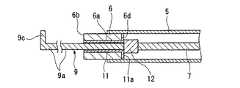
本実施形態の高周波ナイフ(内視鏡用処置具)1は、図1から図3に示すように、内視鏡2の内視鏡挿入部3に形成された処置具チャンネル(チャンネル)4内に挿入され、可撓性を有する絶縁性の挿入部5と、該挿入部5の先端に設けられ、挿入部5の軸線Lに沿って挿通孔6aが形成された管状の第1電極部6と、挿入部5内に進退自在に挿通された導電性の操作ワイヤ(電気導線)7と、挿入部5の基端側に設けられ、操作ワイヤ7を軸線L方向に沿って進退操作する操作部8と、操作ワイヤ7の先端に接続され、挿通孔6a内を進退自在に挿通された棒状の第2電極部9と、操作ワイヤ7の基端側に電気的に接続され、外部から所定の周波数を有する電流(切開用電流又は凝固用電流)を操作ワイヤ7及び第2電極部9に通電する接続コード(外部接続部)10とを備えている。Hereinafter, a first embodiment of an endoscope treatment tool according to the present invention will be described with reference to FIGS. 1 to 5.
As shown in FIGS. 1 to 3, the high-frequency knife (endoscopic treatment tool) 1 of the present embodiment is disposed in a treatment tool channel (channel) 4 formed in an endoscope insertion portion 3 of an
上記挿入部5は、長尺な管状体であり、基端側が上記操作部8の後述する操作部本体15の先端側に固定されている。また、挿入部5の先端側内周面には、上記第1電極部6が該挿入部5の先端から突出するように固定されている。この第1電極部6は、挿入部5の軸線L方向に直交する面に平行な先端面6bを有しており、軸線L方向に伸びる断面円形のパイプ状に形成されている。そして、先端面6bには、挿通孔6aの開口周囲を囲むようにテーパ状の凹部6cが形成されている。また、第1電極部6の内周面(凹部6cの内周面を除く)及び基端面(接触面)6dには絶縁部材11が設けられており、電気的に絶縁された状態になっている。 The
上記操作ワイヤ7は、挿入部5の先端側から基端側に亘って挿通されており、その先端側には導電性のストッパ部材12が接続されている。このストッパ部材12は、操作ワイヤ7より外径の大きい円柱状に形成されており、操作ワイヤ7が先端側に移動したときに共に移動して、第1電極部6の基端面6d側に位置する絶縁部材11の基端面11aに接触するようになっている。 The
上記第2電極部9は、基端側がストッパ部材12に接続されており、軸線L方向に延びる断面円形の棒状部9aと、該棒状部9aの先端に設けられ、軸線L方向に直交する方向に広がる凸部9bとで一体的に形成されている。また、この凸部9bは、図4に示すように、第2電極部9が第1電極部6内に没入したときに、上記凹部6c内に収容される形状に形成されていると共に、収容されたときに先端面6bの平坦性が確保されるように該先端面6bから突出しないようになっている。 The
つまり、第2電極部9は、操作部8による操作ワイヤ7の進退操作に応じて、第1電極部6の先端から突没すると共に、第1電極部6内に没入したときに第1電極部6と電気的に接続するようになっている。即ち、操作ワイヤ7が挿入部5の基端側に移動したときに、第2電極部9が第1電極部6内に没入すると共に、上述したように凸部9bが凹部6c内に収容される。これにより、凸部9bの外周面と凹部6cの内周面とが接触して、第1電極部6と第2電極部9とが電気的に接続されるようになっている。
また、上記ストッパ部材12は、図2に示すように、操作ワイヤ7が挿入部5の先端側に移動したときに、絶縁部材11の基端面11aに接触するので、第2電極部9の突出量を規制する働きをしている。That is, the
Further, as shown in FIG. 2, the
上記操作部8は、図2に示すように、略軸状の操作部本体15と、該操作部本体15に
対して軸線L方向に進退操作(スライド)可能なスライド部16とを備えている。また、操作部本体15及びスライド部16は、プラスチック等の非導電性材料から形成されている。また、操作部本体15には、スライド部16のガイド溝15aが軸線L方向に形成されており、該ガイド溝15aに沿ってスライド部16がスライドするように装着されている。また、スライド部16に操作ワイヤ7の基端側が接続されている。これにより、スライド部16をガイド溝15aに沿ってスライド操作したきに操作ワイヤ7が進退操作されて、上述したように第2電極部9が第1電極部6の先端から突没するようになっている。As shown in FIG. 2, the
また、操作部本体15の基端側には、親指を挿入できる指掛けリング15bが取り付けられており、同様に、スライド部16には人指し指及び中指をそれぞれ挿入できる指掛け孔16aが形成されている。これにより、操作者は、片手で容易に操作部8を操作できるようになっている。
更に、スライド部16には、操作ワイヤ7の基端に電気的に接続される接続端子17が設けられており、該接続端子17に上記接続コード10の導線10aの一端側が接続されている。なお、導線10aは、絶縁性のチューブ10bにより被覆されている。また、この接続コード10の他端側には、高周波電源20の接続ジャック21に差込可能なプラグ10cが設けられている。Further, a
Further, the
上記高周波電源20には、図5に示すように、切開用ペダルスイッチ22及び凝固用ペダルスイッチ23が設けられたフットスイッチ24と、手技の最中に患者の下に敷かれる対極板25とが接続されている。また、高周波電源20には、切開用ペダルスイッチ22を術者が足で踏んだときにのみ、接続コード10に切開用電流を流し、凝固用ペダルスイッチ23を術者が足で踏んだときにのみ、接続コード10に凝固用電流を流す電流通電部26が内蔵されている。 As shown in FIG. 5, the high-
次に、このように構成された高周波ナイフ1により、生体組織を切除する場合について説明する。なお、本実施形態では、消化管の表面にできた図示しない病変部を、粘膜下層を剥離することで切除するESDを例にして説明する。
まず、患者の下に対極板25をセットした後、内視鏡挿入部3を体腔内に挿入してその先端を病変部の近傍に位置させる。次いで、処置具チャンネル4を介して図示しない注射針を体腔内に導入し、病変部近傍の粘膜下層に生理食塩水を局注して病変部を膨隆させる。次いで、図示しない従来の針状の高周波ナイフ1により、病変部近傍の粘膜の一部に全周切開のきっかけとなる孔を開ける。Next, a case where a living tissue is excised with the high-
First, after setting the
次いで、図1に示すように、処置具チャンネル4内に、本実施形態の高周波ナイフ1の挿入部5を挿入して、内視鏡挿入部3の先端から突出させる。この際、図4に示すように、スライド部16を操作部本体15に対して基端側に移動させ、第2電極部9を第1電極部6内に没入させた状態で挿入する。
挿入部5を内視鏡挿入部3の先端から突出させた後、図2及び図3に示すように、スライド部16を操作部本体15に対して先端側に移動させて、第2電極部9を第1電極部6の先端から突出させる。この際、スライド部16が先端側に移動しなくなるまで、即ち、ストッパ部材12が、絶縁部材11の基端面11aに接触するまで移動させる。これにより、第2電極部9の突出量が規制されるので、第2電極部9は確実に所定の長さだけ突出する。これにより、以降の切開処置を行っている最中に不意に第2電極部9が必要以上突出することがないので、切開処置の際の安全性を高めることができる。Next, as shown in FIG. 1, the
After the
第2電極部9を突出させた後、挿入部5全体又は内視鏡挿入部3全体を動かして、第2電極部9の凸部9b及び棒状部9aを病変部近傍の粘膜に開けた孔内に挿入する。この状態を確認した後、術者は切開用ペダルスイッチ22を足で踏み込む。切開用ペダルスイッチ22が踏まれると、電流通電部26は、踏まれている間だけ、切開用電流を接続コード10に流す。この切開用電流は、接続コード10、操作ワイヤ7及びストッパ部材12を介して第2電極部9に通電される。これにより、凸部9b及び棒状部9aに接触している生体組織を局所的に焼灼切開することができる。
特に、第2電極部9は、生体組織との接触面積が比較的小さい棒状であるので、エネルギー密度を高めた状態で、切開用電流を利用して確実に切開処置を行うことができる。After the
In particular, since the
また、上述した切開処置の際、第1電極部6の基端面6dは、絶縁部材11により絶縁状態になっているので、ストッパ部材12を介して切開用電流が流れることはない。更に、第1電極部6の内周面も同様に、絶縁部材11により絶縁状態になっているので、切開処置を行っているときに、挿通孔6aと第2電極部9とが接触したとしても切開用電流が第1電極部6に流れることはない。
よって、切開処置時に第2電極部9が処置具チャンネル4に接触したり、生体組織に接触したりしても何ら問題なく、安全に切開処置を行うことができる。
そして、病変部を中心として該病変部周囲の粘膜を、第2電極部9による切開処置にて全周切開する。特に、第2電極部9の先端には凸部9bが設けられているので、該凸部9bに粘膜を引っ掛けながら切開でき、切開処置を行い易い。Further, at the time of the incision treatment described above, the
Therefore, the incision treatment can be performed safely without any problem even if the
Then, the entire mucous membrane around the lesioned part is incised by the
ここで、上述した切開処置を行っている最中に出血が確認された場合には、術者は、切開用ペダルスイッチ22から足を外して切開用電流の通電を停止した後、図4に示すように、スライド部16を操作部本体15の基端側に移動させて第2電極部9を第1電極部6内に没入させる。この没入により、第2電極部9の凸部9bは、第1電極部6の凹部6c内に完全に収容され、先端面6bの平坦性が確実に確保される。また、凸部9bの外周面と凹部6cの内周面とが接触するので、第1電極部6と第2電極部9とが電気的に接続された状態となる。 Here, when bleeding is confirmed during the above-described incision procedure, the operator removes his / her foot from the incision pedal switch 22 to stop energization of the incision current, As shown, the
第2電極部9を収容した後、術者は、挿入部5全体又は内視鏡挿入部3全体を動かして、第1電極部6の先端面6b(第2電極部9の凸部9bの先端を含む)を出血部位を含む生体組織に押し付ける。この状態を確認した後、術者は、凝固用ペダルスイッチ23を足で踏み込む。凝固用ペダルスイッチ23が踏まれると、電流通電部26は、踏まれている間だけ、凝固用電流を接続コード10に流す。この凝固用電流は、接続コード10、操作ワイヤ7、ストッパ部材12及び第2電極部9を介して第1電極部6に通電される。その結果、先端面6bに接触している出血部位及びその周辺の生態組織を焼灼して止血する凝固処置を行うことができる。 After accommodating the
特に、生体組織との接触面積が大きな先端面6bで凝固処置を行えるので、エネルギー密度を小さくした状態で、凝固用電流を利用して確実に凝固処置を行うことができる。
また、この凝固処置を行う際に、凹部6c内に凸部9bが収容されているので、先端面6bを押し付けたときに、該生体組織を均等に焼灼して止血を確実に行うことができる。更に、挿通孔6aの開口から異物等が第1電極部6内に侵入することを防止できるので、異物混入による不具合をなくすことができる。In particular, since the coagulation treatment can be performed on the
Further, when the coagulation treatment is performed, the
そして、上述した凝固処置を適時行いながら止血を行い、粘膜の全周切開を行う。全周切開後、再度第2電極部9を用いて粘膜下層を焼灼切開して剥離する。また、この粘膜下層の剥離を行っているときに、出血が確認された場合には、上述したと同様に第1電極部6を用いて凝固処置を行う。そして、粘膜下層の剥離が終了した後、処置具チャンネル4を介して、例えば、把持鉗子を導入し、該把持鉗子により病変部を把持して消化管から分離させる。これにより、病変部を粘膜下層を含んだ状態で切除することができる。 Then, hemostasis is performed while performing the above-described coagulation treatment in a timely manner, and a whole-incision of the mucous membrane is performed. After the entire incision, the second mucosa layer is again used to cauterize and peel off the submucosal layer. Further, when bleeding is confirmed during the peeling of the submucosal layer, a coagulation treatment is performed using the
上述したように本実施形態の高周波ナイフ1によれば、従来のように切開用の処置具又は凝固用の処置具を入れ替えたり、切開用の電極及び凝固用の電極に接続されているプラグを差し替えたりする必要がなく、操作部8の進退操作だけで切開処置又は凝固処置を速やかに切り替えながら適時行うことができるので、操作が容易であり手間がかかることはない。そのため、手技時間を短縮することができ、患者への負担を極力低減することができる。また、切開処置又は凝固処置を行う際に、それぞれに適した形状の電極部(第1電極部6又は第2電極部9)を、最適な周波数の電流(切開用電流又は凝固用電流)で使い分けて使用することができるので、切開処置又は凝固処置をそれぞれ確実に行うことができる。 As described above, according to the high-
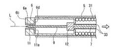
次に、本発明に係る内視鏡用処置具の第2実施形態を、図6及び図7を参照して以下に説明する。なお、この第2実施形態においては、第1実施形態における構成要素と同一の部分については、同一の符号を付しその説明を省略する。
第2実施形態と第1実施形態との異なる点は、第1実施形態の高周波ナイフ1では第2電極部9を第1電極部6内に没入させた時に、凸部9bの外周面と凹部6cの内周面とが接触することで、第1電極部6と第2電極部9とが電気的に接続される構成であったのに対し、第2実施形態の高周波ナイフ30は、第2電極部9を第1電極部6内に没入させた時に、ストッパ部材12及びコイル31を介して第1電極部6と第2電極部9とが電気的に接続される点である。Next, a second embodiment of the endoscope treatment tool according to the present invention will be described below with reference to FIGS. In the second embodiment, the same components as those in the first embodiment are denoted by the same reference numerals, and the description thereof is omitted.
The difference between the second embodiment and the first embodiment is that in the high-
即ち、本実施形態の高周波ナイフ30は、図6及び図7に示すように、挿入部5の内周面に先端側から基端側に亘って密巻きの上記コイル31が固定されている。このコイル31は、先端が第1電極部6に接続されており、基端が操作部本体15の先端側に接続されている。また、コイル31には、第2電極部9を第1電極部6内に完全に没入させた時に、ストッパ部材12の基端側に接触する絞り部32が設けられている。即ち、この絞り部32は、第2電極部9を没入させたときに、ストッパ部材12と第1電極部6とを電気的に接続する電気接続部として機能するようになっている。また、本実施形態の第2電極部9は、先端が尖った針状部材とされている。 That is, in the high-
また、本実施形態の高周波ナイフ30は、操作ワイヤ7の周囲に絶縁被覆33が被せられている。これにより、操作ワイヤ7に切開用電流又は凝固用電流が流れているときに、挿入部5が湾曲したとしても、操作ワイヤ7とコイル31とが電気的に接触することはない。特に、操作ワイヤ7と絞り部32との間における、意図しない電気的な接触を防止することができる。 In addition, the high-
このように構成された高周波ナイフ30により切開処置を行った場合には、第2電極部9が針状部材であるので、生体組織との接触面積をより小さくすることができる。従って、よりシャープな切れ味を確保することができ、切開が必要な箇所だけを高精度に切開することができる。 When an incision treatment is performed with the high-
また、凝固処置を行う場合には、図7に示すように、スライド部16を操作部本体15に対して基端側に移動させて、第2電極部9を第1電極部6内に没入させる。そして、この操作に伴ってストッパ部材12が移動し、コイル31の絞り部32に接触する。なお、このストッパ部材12と絞り部32とが接触した時点で、第2電極部9は完全に第1電極部6内に没入するので、第1電極部6の先端面6bの平坦性が確保される。また、この状態になった後は、スライド部16がこれ以上基端側に移動しないので、術者はスライド部16の動きが規制されたことを受けて、確実にストッパ部材12と絞り部32とが接触したことを把握することができる。 Further, when performing the coagulation treatment, the
次いで、第1実施形態と同様に、高周波電源20から凝固用電流を接続コード10に流す。これにより、第1電極部6には、操作ワイヤ7、ストッパ部材12及びコイル31を介して凝固用電流が通電される。なお、第2電極部9にもストッパ部材12を介して凝固用電流が通電されている。また、コイル31の基端側は、非導電性の操作部本体15に接続されているので、コイル31に流れた凝固用電流は確実に第1電極部6に通電される。 Next, as in the first embodiment, a coagulation current is passed from the high
よって、第1実施形態と同様に、先端面6bを生体組織に押し付けて凝固処置を行うことができる。更に、本実施形態の高周波ナイフ30は、コイル31を備えているので、第1実施形態の高周波ナイフ1に比べて、圧縮、引張りや捩れ等に対する強度が向上している。従って、操作性をより向上することができる。 Therefore, similarly to the first embodiment, the
次に、第1実施形態の高周波ナイフ1を備えた本発明に係る内視鏡用処置具システム40について、図8を参照して説明する。
本実施形態の内視鏡用処置具システム40は、高周波ナイフ1と、スライド部16の進退方向における位置を検出する検出手段41と、電流通電部26を任意のタイミングで作動させるフットスイッチ(スイッチ)42と、検出手段41による検出結果に基づいて電流通電部26の電流出力設定を自動的に変化させる制御部43とを備えている。この制御部43は、高周波電源20内に内蔵されている。Next, an endoscope
The endoscope
上記検出手段41は、スライド部16に一端が接続され、操作ワイヤ7の周囲を覆うワイヤカバー45と、該ワイヤカバー45の外周面に固定されたプラグ46と、操作部本体15に固定され、プラグ46を間に挟むように操作部本体15の基端側及び先端側に設けられた第1の検出部47及び第2の検出部48と、第1の検出部47及び第2の検出部48に電気的に接続され、両検出部47、48からの各出力信号を受信する検出部本体49とを備えている。 The detection means 41 is connected to the
第1の検出部47は、スライド部16を操作部本体15に対して基端側に移動させ、第2電極部9の凸部9bを第1電極部6の凹部6c内に収容したときに、プラグ46と接触する位置に設けられており、接触したときに検出部本体49に第1の出力信号を出力するようになっている。また、第2の検出部48は、スライド部16を操作部本体15に対して先端側に移動させ、ストッパ部材12が絶縁部材11の基端面11aに接触したときに、プラグ46と接触する位置に設けられており、接触したときに検出部本体49に第2の出力信号を出力するようになっている。 When the
検出部本体49は、高周波電源20内に内蔵されており、送られてきた第1の検出信号又は第2の検出信号に基づいてスライド部16の位置を検出し、その旨を制御部43に知らせるようになっている。つまり、制御部43は、術者が切開処置を行うのか又は凝固処置を行うのかを事前に認識することができる。そして、制御部43は、この検出部本体49からの情報を基に、電流通電部26の電流出力設定を自動的に変化させる。
つまり、スライド部16が先端側に移動して、プラグ46と第2の検出部48とが接触していると検出されたときには、制御部43は切開用電流が流れるように電流通電部26の電流出力設定を変更する。一方、スライド部16が基端側に移動して、プラグ46と第1の検出部47とが接触していると検出されたときには、制御部43は凝固用電流が流れるように電流通電部26の電流出力設定を変更する。そして、電流通電部26は、フットスイッチ42が踏まれたときに、制御部43で設定された電流出力設定で電流を流す。The detection unit
That is, when it is detected that the
このように構成された内視鏡用処置具システム40によれば、術者が手技を行っているときに、スライド部16の動きに関連してどちらの電流を流すか選択する必要がなく、単にフットスイッチ42を踏み込むだけで、スライド部16の位置に関連した電流、即ち、切開用電流又は凝固用電流を第1電極部6又は第2電極部9に自動的に流すことができる。よって、手技に応じた電流を間違えることなく確実に流すことができるので、操作し易くなると共に、手元の操作だけにより集中することができる。その結果、さらなる手技の安全性を高めることができる。 According to the endoscope
なお、本発明の技術範囲は上記実施の形態に限定されるものではなく、本発明の趣旨を逸脱しない範囲において種々の変更を加えることが可能である。 The technical scope of the present invention is not limited to the above embodiment, and various modifications can be made without departing from the spirit of the present invention.
例えば、上記各実施形態では、絶縁部材により第1電極部の内周面及び基端面を絶縁状態に形成したが、これに限られず例えば、絶縁性材料をコーティングすることで絶縁状態に形成しても構わない。
また、第1電極部を挿入部の先端から突出させた構成にしたが、このときに第1の電極部の外周面についても同様に絶縁状態に形成しても構わない。こうすることで、第1電極部に電流が通電されているときに、該第1電極部と処置具チャンネル又は生体組織とが接触したとしても問題なく、より安全性を高めることができる。
例えば、図9に示すように、挿入部5をさらに先端側に延ばし、第1電極部6の外周面を覆うように構成して、外周面を絶縁状態にしても構わない。For example, in each of the above-described embodiments, the inner peripheral surface and the base end surface of the first electrode portion are formed in an insulating state by the insulating member. However, the present invention is not limited to this. It doesn't matter.
In addition, the first electrode portion is configured to protrude from the distal end of the insertion portion, but at this time, the outer peripheral surface of the first electrode portion may be similarly formed in an insulating state. By doing so, even when a current is passed through the first electrode part, even if the first electrode part and the treatment instrument channel or the living tissue come into contact with each other, there is no problem and safety can be further improved.
For example, as illustrated in FIG. 9, the
また、上記各実施形態において、第1電極部を、先端面を有する断面円形のパイプ状に形成したが、この形状に限られるものではない。例えば、図10に示すように、先端側が球状になっていても構わない。
更に、第2電極部を、先端に凸部を有する形状や針状に形成したが、この形状に限られるものではない。例えば、図11に示すように、先端が略90度屈曲した屈曲部9cを有する形状であっても構わない。Moreover, in each said embodiment, although the 1st electrode part was formed in the cross-sectional circular pipe shape which has a front end surface, it is not restricted to this shape. For example, as shown in FIG. 10, the tip side may be spherical.
Furthermore, although the 2nd electrode part was formed in the shape and needle shape which have a convex part in the front-end | tip, it is not restricted to this shape. For example, as shown in FIG. 11, it may have a shape having a
また、第1電極部の内周面及び基端面に絶縁部材を設け、第2電極部が突出したときに第1電極部とストッパ部材との間を絶縁状態にしたが、この場合に限られず、例えば、図12に示すように、絶縁部材11を第1電極部6の内周面だけに設け、ストッパ部材12が第1電極部6の基端面6dに接触したときに両者6、12の間が絶縁状態となるように、ストッパ部材12の外周側に絶縁領域12aを形成しても構わない。 In addition, an insulating member is provided on the inner peripheral surface and the base end surface of the first electrode portion, and the first electrode portion and the stopper member are insulated when the second electrode portion protrudes. However, the present invention is not limited to this case. For example, as shown in FIG. 12, when the insulating
また、第2実施形態において、ストッパ部材と第1電極部とをコイルにより電気的に接続したが、コイルに限られるものではない。例えば、図13に示すように、第2電極部6を第1電極部9内に没入させたときに、ストッパ部材12と第1電極部6とを電気的に接続する管状パイプ50を挿入部5の内周面に固定しても構わないし、図14に示すように、第1電極部6の基端側を挿入部5の基端側にさらに延ばして、ストッパ部材12に直接電気的に接触するように形成しても構わない。
但し、挿入部の柔軟性及び強度向上の観点から、図13及び図14に示すいずれの場合よりも、第2実施形態に示したようにコイルを電気接続部として利用することがより好ましい。In the second embodiment, the stopper member and the first electrode portion are electrically connected by the coil, but the present invention is not limited to the coil. For example, as shown in FIG. 13, when the
However, from the viewpoint of improving the flexibility and strength of the insertion portion, it is more preferable to use the coil as the electrical connection portion as shown in the second embodiment than in any case shown in FIGS. 13 and 14.
また、第1実施形態の高周波ナイフを備えた高周波処置具システムを説明したが、第2実施形態の高周波ナイフを備えた高周波処置具システムでも構わない。 Moreover, although the high frequency treatment tool system provided with the high frequency knife of 1st Embodiment was demonstrated, the high frequency treatment tool system provided with the high frequency knife of 2nd Embodiment may be sufficient.
L 軸線
1、30 高周波ナイフ(内視鏡用処置具)
2 内視鏡
4 処置具チャンネル(チャンネル)
5 挿入部
6 第1電極部
6a 挿通孔
6b 第1電極部の先端面
6c 第1電極部の凹部
6d 第1電極部の基端面(接触面)
7 操作ワイヤ(電気導線)
8 操作部
9 第2電極部
9b 第2電極部の凸部
10 接続コード(外部接続部)
12 ストッパ部材
26 電流通電部
31 コイル(電気接続部)
40 内視鏡用処置具システム
41 検出手段
42 フットスイッチ(スイッチ)
43 制御部
2 Endoscope 4 Treatment tool channel (channel)
DESCRIPTION OF
7 Operation wire (electrical conductor)
8
12
40 Endoscope
43 Control unit
Claims (8)
Translated fromJapanese該挿入部の先端に設けられ、挿入部の軸線に沿って挿通孔が形成された管状の第1電極部と、
前記第1電極部の先端で、前記挿通孔の開口周囲を囲むように形成された凹部と、
前記挿入部内に進退自在に挿通された導電性の電気導線と、
前記挿入部の基端側に設けられ、前記電気導線を前記軸線方向に沿って進退操作する操作部と、
前記電気導線の先端に接続され、前記挿通孔内を進退自在に挿通された棒状の第2電極部と、
前記第2電極部の先端に設けられ、前記軸線方向に直交する方向に広がる凸部と、
前記電気導線の基端側に電気的に接続され、外部から所定の周波数を有する電流を電気導線及び前記第2電極部に通電させる外部接続部とを備え、
前記第2電極部は、前記操作部による進退操作に応じて前記第1電極部の先端から突没すると共に、第1電極部内に没入したときに第1電極部と電気的に接続し、前記凸部は、前記第2電極部が前記第1電極部内に没入したときに、前記第1電極部の先端面と前記第2電極部の先端面とが連続した面を形成するように前記凹部内に収容されることを特徴とする内視鏡用処置具。An insulative insertion portion that is inserted into the endoscope channel and has flexibility;
A tubular first electrode portion provided at the distal end of the insertion portion and having an insertion hole formed along the axis of the insertion portion;
A recess formed to surround the periphery of the opening of the insertion hole at the tip of the first electrode portion;
A conductive electrical conductor inserted in the insertion portion so as to freely advance and retract; and
An operation unit that is provided on a proximal end side of the insertion unit, and that advances and retracts the electric conducting wire along the axial direction;
A rod-shaped second electrode portion connected to the tip of the electric conducting wire and inserted in the insertion hole so as to be freely advanced and retracted;
A convex portion provided at a tip of the second electrode portion and extending in a direction perpendicular to the axial direction;
An external connection part electrically connected to the proximal end side of the electrical lead, and for passing a current having a predetermined frequency from the outside to the electrical lead and the second electrode part,
The second electrode part protrudes and sunk from the tip of the first electrode part in response to an advance / retreat operation by the operation part, and is electrically connectedto the first electrode part when immersed in the first electrode part, The convex portion is formed in the concave portion so as to form a continuous surface between the distal end surface of the first electrode portion and the distal end surface of the second electrode portion when the second electrode portion is immersed in the first electrode portion. A treatment instrument for an endoscopewhich is housed in the endoscope.
該挿入部の先端に設けられ、挿入部の軸線に沿って挿通孔が形成された管状の第1電極部と、 A tubular first electrode portion provided at the distal end of the insertion portion and having an insertion hole formed along the axis of the insertion portion;
前記第1電極部の先端で、前記挿通孔の開口周囲を囲むように形成された凹部と、 A recess formed to surround the periphery of the opening of the insertion hole at the tip of the first electrode portion;
前記挿入部内に進退自在に挿通された導電性の電気導線と、 A conductive electrical conductor inserted in the insertion portion so as to freely advance and retract; and
前記挿入部の基端側に設けられ、前記電気導線を前記軸線方向に沿って進退操作する操作部と、 An operation unit that is provided on a proximal end side of the insertion unit, and that advances and retracts the electric conducting wire along the axial direction;
前記電気導線の先端に接続され、前記挿通孔内を進退自在に挿通された棒状の第2電極部と、 A rod-shaped second electrode portion connected to the tip of the electric conducting wire and inserted in the insertion hole so as to be freely advanced and retracted;
前記第2電極部の先端に設けられ、前記軸線方向に直交する方向に広がる凸部と、 A convex portion provided at a tip of the second electrode portion and extending in a direction perpendicular to the axial direction;
前記電気導線の基端側に電気的に接続され、外部から所定の周波数を有する電流を電気導線及び前記第2電極部に通電させる外部接続部と、 An external connection portion that is electrically connected to the proximal end side of the electric conducting wire, and causes an electric current having a predetermined frequency from the outside to pass through the electric conducting wire and the second electrode portion;
前記電気導線と前記第2電極部との間に設けられ、第2電極部を突出させたときに第1電極部の基端側に接触して、該第2電極部の突出量を規制すると共に、接触したときに前記第1電極部との間が絶縁状態となるストッパ部材と、 Provided between the electrical conductor and the second electrode part, when the second electrode part is projected, it comes into contact with the proximal end side of the first electrode part and regulates the protruding amount of the second electrode part. And a stopper member that is insulated from the first electrode portion when contacted,
を備え、With
前記第2電極部は、前記操作部による進退操作に応じて前記第1電極部の先端から突没すると共に、第1電極部内に没入したときに第1電極部と電気的に接続し、前記凸部は、前記第2電極部が前記第1電極部内に没入したときに前記凹部内に収容されることを特徴とする内視鏡用処置具。 The second electrode part protrudes and sunk from the tip of the first electrode part in response to an advance / retreat operation by the operation part, and is electrically connected to the first electrode part when immersed in the first electrode part, An endoscopic treatment instrument, wherein the convex portion is accommodated in the concave portion when the second electrode portion is immersed in the first electrode portion.
該挿入部の先端に設けられ、挿入部の軸線に沿って挿通孔が形成された管状の第1電極部と、 A tubular first electrode portion provided at the distal end of the insertion portion and having an insertion hole formed along the axis of the insertion portion;
前記挿入部内に進退自在に挿通された導電性の電気導線と、 A conductive electrical conductor inserted in the insertion portion so as to freely advance and retract; and
前記挿入部の基端側に設けられ、前記電気導線を前記軸線方向に沿って進退操作する操作部と、 An operation unit that is provided on a proximal end side of the insertion unit, and that advances and retracts the electric conducting wire along the axial direction;
前記電気導線の先端に接続され、前記挿通孔内を進退自在に挿通された棒状の第2電極部と、 A rod-shaped second electrode portion connected to the tip of the electric conducting wire and inserted in the insertion hole so as to be freely advanced and retracted;
前記電気導線の基端側に電気的に接続され、外部から所定の周波数を有する電流を電気導線及び前記第2電極部に通電させる外部接続部と、 An external connection portion that is electrically connected to the proximal end side of the electric conducting wire, and causes an electric current having a predetermined frequency from the outside to pass through the electric conducting wire and the second electrode portion;
前記電気導線と前記第2電極部との間に設けられ、第2電極部を突出させたときに第1電極部の基端側に接触して、該第2電極部の突出量を規制する導電性のストッパ部材と、 Provided between the electrical conductor and the second electrode part, when the second electrode part is projected, it comes into contact with the proximal end side of the first electrode part and regulates the protruding amount of the second electrode part. A conductive stopper member;
前記第2電極部を没入させたときに、前記ストッパ部材と前記第1電極部とを電気的に接続する電気接続部と、 An electrical connection portion for electrically connecting the stopper member and the first electrode portion when the second electrode portion is immersed;
を備え、With
前記第1電極部は、前記第2電極部の突出時に前記ストッパ部材と接触する接触面が、電気的に絶縁状態に形成されており、 The first electrode portion has a contact surface that contacts the stopper member when the second electrode portion protrudes, and is electrically insulated.
前記第2電極部は、前記操作部による進退操作に応じて前記第1電極部の先端から突没すると共に、第1電極部内に没入したときに第1電極部と電気的に接続することを特徴とする内視鏡用処置具。 The second electrode part protrudes and sunk from the tip of the first electrode part in response to an advance / retreat operation by the operation part, and is electrically connected to the first electrode part when immersed in the first electrode part. An endoscopic treatment tool.
前記第2電極部は、針状部材であることを特徴とする内視鏡用処置具。The endoscope treatment tool accordingto claim 3 ,
The endoscope treatment instrument, wherein the second electrode portion is a needle-like member.
前記第1電極部は、内周面が電気的に絶縁状態に形成されていることを特徴とする内視鏡用処置具。The endoscope treatment tool according toany one of claims 1 to 4 ,
An endoscopic treatment instrument, wherein the first electrode portion has an inner peripheral surface formed in an electrically insulated state.
前記第1電極部の先端面は、前記軸線方向に直交する面に平行であることを特徴とする内視鏡用処置具。The endoscope treatment tool according toany one of claims 1 to 5 ,
An endoscope treatment tool, wherein a distal end surface of the first electrode portion is parallel to a surface orthogonal to the axial direction .
前記第1電極部は、外周面全体が電気的に絶縁状態に形成されていることを特徴とする内視鏡用処置具。The endoscopic treatment tool according toany one of claims 1 to 6 ,
The first electrode portion is an endoscope treatment tool, wherein the entire outer peripheral surface is formed in an electrically insulated state.
前記操作部の前記進退方向における位置を検出する検出手段と、
前記外部接続部に電気的に接続され、前記所定の周波数を有する電流を通電する電流通電部と、
該電流通電部を任意のタイミングで作動させるスイッチと、
前記検出手段による検出結果に基づいて、前記電流通電部の電流出力設定を自動的に変化させる制御部とを備えていることを特徴とする内視鏡用処置具システム。The endoscopic treatment tool according toany one of claims 1 to 7 ,
Detecting means for detecting a position of the operation unit in the forward / backward direction;
A current conducting unit electrically connected to the external connecting unit and energizing a current having the predetermined frequency;
A switch for operating the current-carrying unit at an arbitrary timing;
An endoscopic treatment instrument system comprising: a control unit that automatically changes a current output setting of the current energization unit based on a detection result by the detection unit.
Priority Applications (4)
| Application Number | Priority Date | Filing Date | Title |
|---|---|---|---|
| JP2005157050AJP4643361B2 (en) | 2005-05-30 | 2005-05-30 | Endoscope treatment tool and endoscope treatment tool system |
| DE602006004251TDE602006004251D1 (en) | 2005-05-30 | 2006-05-26 | Instrument for endoscope and instrument system for endoscope. |
| EP06010911AEP1728462B1 (en) | 2005-05-30 | 2006-05-26 | Instrument for endoscope and instrument system for endoscope |
| US11/441,731US7731714B2 (en) | 2005-05-30 | 2006-05-26 | Instrument for endoscope and instrument system for endoscope |
Applications Claiming Priority (1)
| Application Number | Priority Date | Filing Date | Title |
|---|---|---|---|
| JP2005157050AJP4643361B2 (en) | 2005-05-30 | 2005-05-30 | Endoscope treatment tool and endoscope treatment tool system |
Publications (2)
| Publication Number | Publication Date |
|---|---|
| JP2006326157A JP2006326157A (en) | 2006-12-07 |
| JP4643361B2true JP4643361B2 (en) | 2011-03-02 |
Family
ID=36968961
Family Applications (1)
| Application Number | Title | Priority Date | Filing Date |
|---|---|---|---|
| JP2005157050AExpired - Fee RelatedJP4643361B2 (en) | 2005-05-30 | 2005-05-30 | Endoscope treatment tool and endoscope treatment tool system |
Country Status (4)
| Country | Link |
|---|---|
| US (1) | US7731714B2 (en) |
| EP (1) | EP1728462B1 (en) |
| JP (1) | JP4643361B2 (en) |
| DE (1) | DE602006004251D1 (en) |
Families Citing this family (75)
| Publication number | Priority date | Publication date | Assignee | Title |
|---|---|---|---|---|
| US8715281B2 (en)* | 2006-03-09 | 2014-05-06 | Olympus Medical Systems Corp. | Treatment device for endoscope |
| EP2049034B1 (en)* | 2006-07-20 | 2012-01-11 | Boston Scientific Limited | Multifunction medical device and related methods of use |
| JP4600683B2 (en)* | 2006-07-31 | 2010-12-15 | 富士フイルム株式会社 | High frequency treatment tool |
| JP4398479B2 (en)* | 2007-03-02 | 2010-01-13 | オリンパスメディカルシステムズ株式会社 | Endoscope device |
| CN100459947C (en)* | 2007-03-09 | 2009-02-11 | 中国人民解放军第三军医大学第一附属医院 | bloodless liver knife |
| JP5048391B2 (en)* | 2007-04-27 | 2012-10-17 | 直久 矢作 | Endoscopic treatment tool |
| JP2008295905A (en)* | 2007-06-04 | 2008-12-11 | Hoya Corp | Monopolar type high frequency knife for endoscope |
| US8663221B2 (en)* | 2007-06-08 | 2014-03-04 | Olympus Medical Systems Corp. | Endoscopic treatment tool |
| JP2009090003A (en)* | 2007-10-11 | 2009-04-30 | Fujinon Corp | High-frequency treatment instrument for endoscope |
| JP2009112788A (en)* | 2007-10-17 | 2009-05-28 | Takashi Toyonaga | High frequency tool |
| US9125562B2 (en) | 2009-07-01 | 2015-09-08 | Avinger, Inc. | Catheter-based off-axis optical coherence tomography imaging system |
| US8696695B2 (en) | 2009-04-28 | 2014-04-15 | Avinger, Inc. | Guidewire positioning catheter |
| US9788790B2 (en) | 2009-05-28 | 2017-10-17 | Avinger, Inc. | Optical coherence tomography for biological imaging |
| US8062316B2 (en)* | 2008-04-23 | 2011-11-22 | Avinger, Inc. | Catheter system and method for boring through blocked vascular passages |
| JP5415727B2 (en)* | 2008-08-13 | 2014-02-12 | オリンパスメディカルシステムズ株式会社 | Endoscopic treatment tool |
| JP5601776B2 (en)* | 2009-02-09 | 2014-10-08 | Hoya株式会社 | Endoscopic high-frequency treatment instrument |
| WO2011003006A2 (en) | 2009-07-01 | 2011-01-06 | Avinger, Inc. | Atherectomy catheter with laterally-displaceable tip |
| WO2011077850A1 (en)* | 2009-12-22 | 2011-06-30 | オリンパスメディカルシステムズ株式会社 | Treatment device for endoscope |
| US8465488B2 (en) | 2010-03-16 | 2013-06-18 | Olympus Medical Systems Corporation | Endoscopic surgical instrument |
| JP2011212315A (en)* | 2010-03-31 | 2011-10-27 | Fujifilm Corp | High frequency treatment instrument for endoscope |
| EP2582306B1 (en)* | 2010-06-15 | 2023-03-29 | Avenu Medical, Inc. | Systems and methods for creating arteriovenous (av) fistulas |
| US11382653B2 (en) | 2010-07-01 | 2022-07-12 | Avinger, Inc. | Atherectomy catheter |
| US9345510B2 (en) | 2010-07-01 | 2016-05-24 | Avinger, Inc. | Atherectomy catheters with longitudinally displaceable drive shafts |
| WO2014039096A1 (en) | 2012-09-06 | 2014-03-13 | Avinger, Inc. | Re-entry stylet for catheter |
| US10548478B2 (en) | 2010-07-01 | 2020-02-04 | Avinger, Inc. | Balloon atherectomy catheters with imaging |
| EP2691038B1 (en) | 2011-03-28 | 2016-07-20 | Avinger, Inc. | Occlusion-crossing devices, imaging, and atherectomy devices |
| US9949754B2 (en) | 2011-03-28 | 2018-04-24 | Avinger, Inc. | Occlusion-crossing devices |
| EP3653151A1 (en) | 2011-10-17 | 2020-05-20 | Avinger, Inc. | Atherectomy catheters and non-contact actuation mechanism for catheters |
| US9345406B2 (en) | 2011-11-11 | 2016-05-24 | Avinger, Inc. | Occlusion-crossing devices, atherectomy devices, and imaging |
| JP5755121B2 (en)* | 2011-11-30 | 2015-07-29 | Hoya株式会社 | Endoscopic high-frequency treatment instrument |
| JP5884534B2 (en)* | 2012-02-06 | 2016-03-15 | 住友ベークライト株式会社 | High frequency treatment tool |
| US9557156B2 (en) | 2012-05-14 | 2017-01-31 | Avinger, Inc. | Optical coherence tomography with graded index fiber for biological imaging |
| WO2013172970A1 (en) | 2012-05-14 | 2013-11-21 | Avinger, Inc. | Atherectomy catheters with imaging |
| EP2849660B1 (en) | 2012-05-14 | 2021-08-25 | Avinger, Inc. | Atherectomy catheter drive assemblies |
| US9498247B2 (en) | 2014-02-06 | 2016-11-22 | Avinger, Inc. | Atherectomy catheters and occlusion crossing devices |
| US11284916B2 (en) | 2012-09-06 | 2022-03-29 | Avinger, Inc. | Atherectomy catheters and occlusion crossing devices |
| EP2910212A4 (en)* | 2012-10-17 | 2016-06-22 | Olympus Corp | High frequency knife |
| CN105228514B (en) | 2013-03-15 | 2019-01-22 | 阿维格公司 | Optical Pressure Sensor Assembly |
| US11096717B2 (en) | 2013-03-15 | 2021-08-24 | Avinger, Inc. | Tissue collection device for catheter |
| WO2014143064A1 (en) | 2013-03-15 | 2014-09-18 | Avinger, Inc. | Chronic total occlusion crossing devices with imaging |
| EP3019096B1 (en) | 2013-07-08 | 2023-07-05 | Avinger, Inc. | System for identification of elastic lamina to guide interventional therapy |
| WO2015107802A1 (en) | 2014-01-14 | 2015-07-23 | オリンパス株式会社 | Incision instrument |
| MX2016010141A (en) | 2014-02-06 | 2017-04-06 | Avinger Inc | Atherectomy catheters and occlusion crossing devices. |
| US9613729B2 (en) | 2014-05-20 | 2017-04-04 | Uchicago Argonne Llc | Mechanical design of multiple zone plates precision alignment apparatus for hard X-ray focusing in twenty-nanometer scale |
| US10357277B2 (en) | 2014-07-08 | 2019-07-23 | Avinger, Inc. | High speed chronic total occlusion crossing devices |
| WO2016021230A1 (en)* | 2014-08-06 | 2016-02-11 | オリンパス株式会社 | High frequency treatment instrument |
| WO2016028835A1 (en) | 2014-08-20 | 2016-02-25 | GYRUS ACMI, INC. (d/b/a OLYMPUS SURGICAL TECHNOLOGIES AMERICA) | Surgical forceps and latching system |
| US10076381B2 (en) | 2014-09-08 | 2018-09-18 | Olympus Corporation | Method of marking lesion in tubular organ of an object |
| CN104546119A (en)* | 2015-01-05 | 2015-04-29 | 张建国 | Mucous membrane detacher |
| US10568520B2 (en) | 2015-07-13 | 2020-02-25 | Avinger, Inc. | Micro-molded anamorphic reflector lens for image guided therapeutic/diagnostic catheters |
| JP6927986B2 (en) | 2016-01-25 | 2021-09-01 | アビンガー・インコーポレイテッドAvinger, Inc. | OCT imaging catheter with delay compensation |
| WO2017145340A1 (en) | 2016-02-25 | 2017-08-31 | オリンパス株式会社 | Manipulator system and operating method therefor |
| WO2017145342A1 (en) | 2016-02-25 | 2017-08-31 | オリンパス株式会社 | Manipulator system and operating method therefor |
| EP3435892B1 (en) | 2016-04-01 | 2024-04-03 | Avinger, Inc. | Atherectomy catheter with serrated cutter |
| US11344327B2 (en) | 2016-06-03 | 2022-05-31 | Avinger, Inc. | Catheter device with detachable distal end |
| WO2018006041A1 (en) | 2016-06-30 | 2018-01-04 | Avinger, Inc. | Atherectomy catheter with shapeable distal tip |
| CN106214247B (en)* | 2016-07-04 | 2018-08-14 | 南京微创医学科技股份有限公司 | A kind of bipolar high frequency electric knife |
| CN107212920A (en)* | 2017-01-23 | 2017-09-29 | 杭州安杰思医学科技有限公司 | Endoscope-use processing unit, endoscope and expandable stent |
| KR102026938B1 (en)* | 2017-06-13 | 2019-09-30 | 주식회사 파인메딕스 | Hybrid knife for endoscope |
| CN108272503B (en)* | 2018-03-07 | 2024-04-19 | 南微医学科技股份有限公司 | Double-channel liquid injection bipolar high-frequency electric knife |
| US12167867B2 (en) | 2018-04-19 | 2024-12-17 | Avinger, Inc. | Occlusion-crossing devices |
| US11083871B2 (en)* | 2018-05-03 | 2021-08-10 | Thermedical, Inc. | Selectively deployable catheter ablation devices |
| WO2020195210A1 (en)* | 2019-03-22 | 2020-10-01 | 株式会社カネカ | Endoscopic treatment instrument |
| US10980402B2 (en)* | 2019-04-03 | 2021-04-20 | Olympus Corporation | Diathermic endotherapeutic device |
| US11564739B2 (en) | 2019-05-06 | 2023-01-31 | Boston Scientific Scimed, Inc. | Medical systems, devices, and related methods |
| CN114746033B (en) | 2019-10-18 | 2025-01-10 | 阿维格公司 | Blocking crossing device |
| US20210353356A1 (en)* | 2020-05-14 | 2021-11-18 | Singlepass Transsepat, Inc. | Tubular large bore transseptal crossing sheath |
| US20220087733A1 (en)* | 2020-09-23 | 2022-03-24 | Baylis Medical Company Inc. | Elongated medical needle |
| TWI759076B (en)* | 2021-01-15 | 2022-03-21 | 陳映臻 | Medicine delivery device for healing body cavity wound and medicine delivery duct thereof |
| JP2022169939A (en)* | 2021-04-28 | 2022-11-10 | 住友ベークライト株式会社 | Needle scalpel for endoscope |
| CN113598933B (en)* | 2021-08-26 | 2024-10-18 | 南微医学科技股份有限公司 | Positioning structure, assembly method, cutter and endoscope system |
| JP2024004890A (en)* | 2022-06-29 | 2024-01-17 | 富士フイルム株式会社 | Endoscope treatment tools and water supply components |
| DE102023134672A1 (en)* | 2022-12-14 | 2024-06-20 | Olympus Medical Systems Corp. | ENDOSCOPIC TREATMENT TOOL |
| JP7744036B2 (en)* | 2023-09-29 | 2025-09-25 | 株式会社 コスミック エム イー | Probe, electric scalpel, robot hand, robot arm, and robot |
| CN120643260A (en)* | 2024-03-13 | 2025-09-16 | 奥林巴斯医疗株式会社 | Treatment tool for endoscope |
Family Cites Families (10)
| Publication number | Priority date | Publication date | Assignee | Title |
|---|---|---|---|---|
| JPS55125858A (en) | 1979-03-19 | 1980-09-29 | Olympus Optical Co | Electric rod for erasion |
| US4682596A (en)* | 1984-05-22 | 1987-07-28 | Cordis Corporation | Electrosurgical catheter and method for vascular applications |
| US4708137A (en) | 1985-05-20 | 1987-11-24 | Olympus Optical Co., Ltd. | High-frequency incision device |
| US5158561A (en) | 1992-03-23 | 1992-10-27 | Everest Medical Corporation | Monopolar polypectomy snare with coagulation electrode |
| DE4323585A1 (en)* | 1993-07-14 | 1995-01-19 | Delma Elektro Med App | Bipolar high-frequency surgical instrument |
| US6056744A (en)* | 1994-06-24 | 2000-05-02 | Conway Stuart Medical, Inc. | Sphincter treatment apparatus |
| JP2002301088A (en)* | 2001-04-05 | 2002-10-15 | Olympus Optical Co Ltd | Endoscopic treatment device |
| JP4109092B2 (en) | 2002-11-21 | 2008-06-25 | オリンパス株式会社 | High frequency knife |
| JP4315725B2 (en)* | 2003-04-17 | 2009-08-19 | オリンパス株式会社 | High frequency knife |
| DE10327237A1 (en)* | 2003-06-17 | 2005-01-13 | Trumpf Medizin Systeme Gmbh + Co. Kg | Electrosurgical instrument for an endoscope |
- 2005
- 2005-05-30JPJP2005157050Apatent/JP4643361B2/ennot_activeExpired - Fee Related
- 2006
- 2006-05-26DEDE602006004251Tpatent/DE602006004251D1/enactiveActive
- 2006-05-26USUS11/441,731patent/US7731714B2/enactiveActive
- 2006-05-26EPEP06010911Apatent/EP1728462B1/enactiveActive
Also Published As
| Publication number | Publication date |
|---|---|
| US20060276784A1 (en) | 2006-12-07 |
| US7731714B2 (en) | 2010-06-08 |
| EP1728462B1 (en) | 2008-12-17 |
| EP1728462A2 (en) | 2006-12-06 |
| EP1728462A3 (en) | 2007-05-30 |
| DE602006004251D1 (en) | 2009-01-29 |
| JP2006326157A (en) | 2006-12-07 |
Similar Documents
| Publication | Publication Date | Title |
|---|---|---|
| JP4643361B2 (en) | Endoscope treatment tool and endoscope treatment tool system | |
| KR100595803B1 (en) | High-frequency knife and endoscopic apparatus | |
| EP2108326B1 (en) | High-frequency treatment apparatus | |
| US5197964A (en) | Bipolar instrument utilizing one stationary electrode and one movable electrode | |
| JP5636449B2 (en) | High frequency treatment tool | |
| JP4870710B2 (en) | High frequency knife and high frequency knife system | |
| US8226646B2 (en) | High frequency treatment instrument | |
| CN100528095C (en) | High-frequency treatment tool | |
| EP0562195A1 (en) | Monopolar polypectomy snare with coagulation electrode | |
| JP5755121B2 (en) | Endoscopic high-frequency treatment instrument | |
| JP7343608B2 (en) | treatment device | |
| JP2004167081A (en) | High-frequency knife | |
| JP2011521723A (en) | Surgical instruments and methods | |
| KR20060059881A (en) | Medical treatment instrument and medical treatment apparatus having same | |
| US20160051313A1 (en) | Attachment for Electrosurgical System | |
| JP2019521775A (en) | Bipolar high frequency electric knife | |
| CN115068100B (en) | Endoscopic surgical tool | |
| JP2001178740A (en) | Endoscopic treatment device | |
| US20110245829A1 (en) | Endoscopic high-frequency treatment instrument | |
| JP2000139942A (en) | High-frequency treating instrument | |
| JP4345703B2 (en) | Electric treatment instrument | |
| JP2009125344A (en) | Endoscopic high-frequency snare device, endoscopic high-frequency snare device and driving device thereof | |
| JP2010131100A (en) | High frequency snare for endoscope | |
| JP7267539B2 (en) | Endoscope Microwave Irradiator | |
| WO2018081820A1 (en) | Attachment for electrosurgical system |
Legal Events
| Date | Code | Title | Description |
|---|---|---|---|
| A621 | Written request for application examination | Free format text:JAPANESE INTERMEDIATE CODE: A621 Effective date:20080318 | |
| A977 | Report on retrieval | Free format text:JAPANESE INTERMEDIATE CODE: A971007 Effective date:20100820 | |
| A131 | Notification of reasons for refusal | Free format text:JAPANESE INTERMEDIATE CODE: A131 Effective date:20100831 | |
| A521 | Request for written amendment filed | Free format text:JAPANESE INTERMEDIATE CODE: A523 Effective date:20101026 | |
| A521 | Request for written amendment filed | Free format text:JAPANESE INTERMEDIATE CODE: A821 Effective date:20101027 | |
| TRDD | Decision of grant or rejection written | ||
| A01 | Written decision to grant a patent or to grant a registration (utility model) | Free format text:JAPANESE INTERMEDIATE CODE: A01 Effective date:20101124 | |
| A01 | Written decision to grant a patent or to grant a registration (utility model) | Free format text:JAPANESE INTERMEDIATE CODE: A01 | |
| A61 | First payment of annual fees (during grant procedure) | Free format text:JAPANESE INTERMEDIATE CODE: A61 Effective date:20101202 | |
| R151 | Written notification of patent or utility model registration | Ref document number:4643361 Country of ref document:JP Free format text:JAPANESE INTERMEDIATE CODE: R151 | |
| FPAY | Renewal fee payment (event date is renewal date of database) | Free format text:PAYMENT UNTIL: 20131210 Year of fee payment:3 | |
| S531 | Written request for registration of change of domicile | Free format text:JAPANESE INTERMEDIATE CODE: R313531 | |
| R350 | Written notification of registration of transfer | Free format text:JAPANESE INTERMEDIATE CODE: R350 | |
| R250 | Receipt of annual fees | Free format text:JAPANESE INTERMEDIATE CODE: R250 | |
| R250 | Receipt of annual fees | Free format text:JAPANESE INTERMEDIATE CODE: R250 | |
| R250 | Receipt of annual fees | Free format text:JAPANESE INTERMEDIATE CODE: R250 | |
| R250 | Receipt of annual fees | Free format text:JAPANESE INTERMEDIATE CODE: R250 | |
| R250 | Receipt of annual fees | Free format text:JAPANESE INTERMEDIATE CODE: R250 | |
| LAPS | Cancellation because of no payment of annual fees |