JP4642660B2 - Radiation field limited device - Google Patents
Radiation field limited deviceDownload PDFInfo
- Publication number
- JP4642660B2 JP4642660B2JP2005517053AJP2005517053AJP4642660B2JP 4642660 B2JP4642660 B2JP 4642660B2JP 2005517053 AJP2005517053 AJP 2005517053AJP 2005517053 AJP2005517053 AJP 2005517053AJP 4642660 B2JP4642660 B2JP 4642660B2
- Authority
- JP
- Japan
- Prior art keywords
- limiting device
- field limiting
- radiation
- irradiation field
- diaphragm
- Prior art date
- Legal status (The legal status is an assumption and is not a legal conclusion. Google has not performed a legal analysis and makes no representation as to the accuracy of the status listed.)
- Expired - Fee Related
Links
- 230000005855radiationEffects0.000titleclaimsdescription210
- 238000005096rolling processMethods0.000claimsdescription42
- 230000007246mechanismEffects0.000claimsdescription35
- 230000005540biological transmissionEffects0.000claimsdescription16
- 239000002184metalSubstances0.000claimsdescription7
- 229910052751metalInorganic materials0.000claimsdescription7
- 230000000903blocking effectEffects0.000claims1
- 238000001514detection methodMethods0.000description7
- 230000002093peripheral effectEffects0.000description6
- 230000003902lesionEffects0.000description5
- 238000005452bendingMethods0.000description4
- 238000005520cutting processMethods0.000description3
- 238000000034methodMethods0.000description3
- NJPPVKZQTLUDBO-UHFFFAOYSA-NnovaluronChemical compoundC1=C(Cl)C(OC(F)(F)C(OC(F)(F)F)F)=CC=C1NC(=O)NC(=O)C1=C(F)C=CC=C1FNJPPVKZQTLUDBO-UHFFFAOYSA-N0.000description3
- 238000001959radiotherapyMethods0.000description3
- 230000008878couplingEffects0.000description2
- 238000010168coupling processMethods0.000description2
- 238000005859coupling reactionMethods0.000description2
- 238000010586diagramMethods0.000description2
- 230000001678irradiating effectEffects0.000description2
- 239000000463materialSubstances0.000description2
- 238000005259measurementMethods0.000description2
- 230000004048modificationEffects0.000description2
- 238000012986modificationMethods0.000description2
- 230000009467reductionEffects0.000description2
- 229910000906BronzeInorganic materials0.000description1
- OAICVXFJPJFONN-UHFFFAOYSA-NPhosphorusChemical compound[P]OAICVXFJPJFONN-UHFFFAOYSA-N0.000description1
- 239000010974bronzeSubstances0.000description1
- 230000008859changeEffects0.000description1
- KUNSUQLRTQLHQQ-UHFFFAOYSA-Ncopper tinChemical compound[Cu].[Sn]KUNSUQLRTQLHQQ-UHFFFAOYSA-N0.000description1
- 230000007423decreaseEffects0.000description1
- 238000006073displacement reactionMethods0.000description1
- 230000000694effectsEffects0.000description1
- 238000009434installationMethods0.000description1
- 238000005461lubricationMethods0.000description1
- 238000003825pressingMethods0.000description1
- 238000003860storageMethods0.000description1
- WFKWXMTUELFFGS-UHFFFAOYSA-NtungstenChemical compound[W]WFKWXMTUELFFGS-UHFFFAOYSA-N0.000description1
- 229910052721tungstenInorganic materials0.000description1
- 239000010937tungstenSubstances0.000description1
Images


Classifications
- G—PHYSICS
- G21—NUCLEAR PHYSICS; NUCLEAR ENGINEERING
- G21K—TECHNIQUES FOR HANDLING PARTICLES OR IONISING RADIATION NOT OTHERWISE PROVIDED FOR; IRRADIATION DEVICES; GAMMA RAY OR X-RAY MICROSCOPES
- G21K1/00—Arrangements for handling particles or ionising radiation, e.g. focusing or moderating
- G21K1/02—Arrangements for handling particles or ionising radiation, e.g. focusing or moderating using diaphragms, collimators
- G21K1/04—Arrangements for handling particles or ionising radiation, e.g. focusing or moderating using diaphragms, collimators using variable diaphragms, shutters, choppers
- G21K1/046—Arrangements for handling particles or ionising radiation, e.g. focusing or moderating using diaphragms, collimators using variable diaphragms, shutters, choppers varying the contour of the field, e.g. multileaf collimators
- A—HUMAN NECESSITIES
- A61—MEDICAL OR VETERINARY SCIENCE; HYGIENE
- A61N—ELECTROTHERAPY; MAGNETOTHERAPY; RADIATION THERAPY; ULTRASOUND THERAPY
- A61N5/00—Radiation therapy
- A61N5/10—X-ray therapy; Gamma-ray therapy; Particle-irradiation therapy
- A61N5/1042—X-ray therapy; Gamma-ray therapy; Particle-irradiation therapy with spatial modulation of the radiation beam within the treatment head
Landscapes
- Physics & Mathematics (AREA)
- Spectroscopy & Molecular Physics (AREA)
- Engineering & Computer Science (AREA)
- General Engineering & Computer Science (AREA)
- High Energy & Nuclear Physics (AREA)
- Radiation-Therapy Devices (AREA)
- Apparatus For Radiation Diagnosis (AREA)
Description
Translated fromJapanese本発明は、放射線治療を行う被検者の病巣部の形状に合わせた放射線の照射野を形成する放射線照射野限定装置に関するものである。 The present invention relates to a radiation irradiation field limiting device for forming a radiation irradiation field in accordance with the shape of a lesion part of a subject who performs radiation therapy.
従来、放射線治療を行う被検者の病巣部に対して放射線を照射する場合に、放射線の照射範囲を限定することにより、この病巣部の形状に合わせた放射線の照射野を形成する放射線照射野限定装置が広く使用されている。
特許文献1は、放射線の照射範囲を限定する絞り動作の軌道面が円筒状であって、その軌道面内周側にラックが刻設された絞りブロック(以下、絞り羽根という)と、この絞り羽根に噛み合うピニオンとを備え、モータの回転を、チェーン等を介してラックとピニオンとに伝達することにより、絞り羽根を駆動する放射線照射野限定装置を開示している。Conventionally, when irradiating a lesion part of a subject undergoing radiation therapy, a radiation irradiation field that forms a radiation field that matches the shape of the lesion part by limiting the radiation irradiation range Limited equipment is widely used.
特許文献2は、摺動面に凹状溝と凸条とが形成された複数の絞り羽根を備え、この複数の絞り羽根を互いに摺動可能に側面方向に配列することにより、摺動面と摺動面との間を通過する放射線を遮蔽する放射線照射野限定装置を開示している。
しかしながら、特許文献1に記載された放射線照射野限定装置では、ラックとピニオンとのガタで絞り羽根の位置精度が低下するので、放射線の照射野を高精度に形成することが困難であった。
また、ラック及びピニオンの幅は、耐久性等を考慮するとあまり小さくできないので(例えば、2mm以下の幅にしてしまうと、耐久性が著しく低下してしまう)、絞り羽根を薄く形成することが困難となり、その結果、限られた設置スペースに絞り羽根を多数配置することができなかった。However, in the radiation field limiting device described in
In addition, since the width of the rack and pinion cannot be made very small in consideration of durability or the like (for example, if the width is 2 mm or less, the durability is remarkably lowered), it is difficult to make the diaphragm blade thin. As a result, many aperture blades could not be arranged in a limited installation space.
なお、上述した絞り羽根の形状が直線形状である場合には、絞り羽根の動作が直線的になるので、この絞り羽根に雌ねじ部を形成し、さらに、モータに連結された駆動軸に雄ねじ部を形成することにより、特許文献1に記載されたラックとピニオンとを用いた放射線照射野限定装置に比べて、絞り羽根を高精度で駆動することができる。
しかし、この場合には、絞り羽根を薄くすると、それに合わせて雌ねじ部及び雄ねじ部の径を小さくする必要がある。その結果、雌ねじ部及び雄ねじ部は、歯の強度が低下してしまい、例えば、歯が摩耗しやすく、歯の潤滑が悪くなり、長期的に安定した動作を行うことが困難となる。In addition, when the shape of the diaphragm blade is a linear shape, the operation of the diaphragm blade is linear. Therefore, a female screw portion is formed on the diaphragm blade, and a male screw portion is formed on the drive shaft connected to the motor. As a result, the diaphragm blades can be driven with higher accuracy than the radiation irradiation field limiting device using the rack and pinion described in
However, in this case, if the aperture blade is made thinner, it is necessary to reduce the diameters of the female screw portion and the male screw portion accordingly. As a result, the strength of the teeth of the female screw portion and the male screw portion is reduced. For example, the teeth are easily worn, the tooth lubrication is deteriorated, and it is difficult to perform a stable operation for a long time.
また、特許文献2に記載された放射線照射野限定装置では、絞り羽根の摺動面に凹状溝を形成するために、薄い絞り羽根を形成することが困難であった。 Moreover, in the radiation irradiation field limiting device described in
本発明の課題は、薄い絞り羽根を複数配列できると共に、この絞り羽根を高精度に駆動することにより、放射線の照射野を高精度に形成できる放射線照射野限定装置を提供することである。 An object of the present invention is to provide a radiation irradiation field limiting device capable of forming a plurality of thin diaphragm blades and forming a radiation irradiation field with high precision by driving the diaphragm blades with high precision.
第1の発明は、厚さ方向に複数配列された絞り羽根を所定量駆動することにより、放射線源から放射される放射線を遮蔽し、前記放射線の照射野を所望の範囲に限定する放射線照射野限定装置において、前記絞り羽根の厚み部分に固定された可撓性を有する線状部材と、前記線状部材を駆動する駆動部と、を備えた放射線照射野限定装置である。 According to a first aspect of the present invention, a plurality of aperture blades arranged in the thickness direction are driven by a predetermined amount to shield radiation radiated from a radiation source and to limit the radiation field to a desired range. In the limiting device, the radiation field limiting device includes a flexible linear member fixed to a thickness portion of the diaphragm blade and a drive unit that drives the linear member.
第2の発明は、第1の発明の放射線照射野限定装置において、前記駆動部は、基台と、駆動源に連結部を介して連結され、前記基台に挿入された駆動軸と、前記駆動軸の回転に伴い、前記駆動軸の軸線方向に沿って移動すると共に、前記線状部材が接続された移動子と、を備えた放射線照射野限定装置である。 According to a second aspect of the present invention, in the radiation field limiting device according to the first aspect of the invention, the drive unit is connected to a base, a drive source via a connection unit, and the drive shaft inserted into the base. The radiation field limiting device includes a moving element that moves along the axial direction of the driving shaft along with the rotation of the driving shaft and to which the linear member is connected.
第3の発明は、第2の発明の放射線照射野限定装置において、前記連結部は、所定以上のトルクの伝達を制限するトルク制限部を備えること、を特徴とする放射線照射野限定装置である。
第4の発明は、第3の発明の放射線照射野限定装置において、前記連結部は、前記駆動軸への駆動力を伝達又は遮断するクラッチ機構を備えること、前記トルク制限部が所定の時間、作動した場合に、前記クラッチ機構を用いて前記駆動軸への前記駆動力の伝達を遮断する制御部を備えること、を特徴とする放射線照射野限定装置である。
第5の発明は、第2の発明の放射線照射野限定装置において、前記連結部は、前記駆動軸への駆動力を伝達又は遮断するクラッチ機構を備えること、前記絞り羽根の位置を検出する位置検出部を備えること、前記絞り羽根を目標位置に移動させるときに、前記位置検出部が前記目標位置に前記絞り羽根が移動したことを検出した場合に、前記クラッチ機構を用いて前記駆動軸への前記駆動力の伝達を遮断し、前記絞り羽根の移動を停止する制御部を備えること、を特徴とする放射線照射野限定装置である。
第6の発明は、第2の発明の放射線照射野限定装置において、前記駆動源の駆動力を複数の前記駆動軸へ伝達する駆動力伝達部と、複数の前記駆動軸への前記駆動力を伝達又は遮断する複数のクラッチ機構と、複数の前記クラッチ機構をそれぞれ制御し、前記駆動源の前記駆動力を前記駆動軸毎に伝達し、複数の前記絞り羽根をそれぞれ駆動可能な制御部とを備えること、を特徴とする放射線照射野限定装置である。
第7の発明は、第2の発明の放射線照射野限定装置において、前記移動子は、雌ねじ部を有し、前記駆動軸は、前記雌ねじ部と噛み合う雄ねじ部を有し、回転駆動されることにより前記移動子を前記駆動軸の前記軸線方向に移動させること、を特徴とする放射線照射野限定装置である。A third invention is the radiation field limiting device according to the second invention, characterized in that in the radiation field limiting device of the second invention, the connecting portion includes a torque limiting unit that limits transmission of a torque exceeding a predetermined value. .
According to a fourth aspect of the present invention, in the radiation field limiting device according to the third aspect of the invention, the connecting portion includes a clutch mechanism that transmits or interrupts the driving force to the driving shaft, and the torque limiting portion has a predetermined time. A radiation irradiation field limiting device comprising: a control unit that, when activated, interrupts transmission of the driving force to the drive shaft using the clutch mechanism.
According to a fifth aspect of the invention, in the radiation field limiting device according to the second aspect of the invention, the connecting portion includes a clutch mechanism that transmits or interrupts the driving force to the driving shaft, and a position that detects the position of the diaphragm blade. When the position detecting unit detects that the diaphragm blade has moved to the target position when the diaphragm blade is moved to the target position, the clutch mechanism is used to move the diaphragm to the drive shaft. The radiation irradiation field limiting device is characterized by comprising a control unit that interrupts the transmission of the driving force and stops the movement of the diaphragm blades.
According to a sixth aspect of the present invention, in the radiation field limiting device of the second aspect of the present invention, the driving force transmission unit that transmits the driving force of the driving source to the plurality of driving shafts, and the driving force to the plurality of driving shafts. A plurality of clutch mechanisms that transmit or shut off, and a control unit that controls each of the plurality of clutch mechanisms, transmits the driving force of the drive source to each of the drive shafts, and can drive the plurality of diaphragm blades, respectively. A radiation irradiation field limiting device.
According to a seventh aspect of the present invention, in the radiation field limiting device according to the second aspect of the invention, the moving element has a female screw part, the drive shaft has a male screw part that meshes with the female screw part, and is driven to rotate. The radiation field limiting device is characterized in that the moving element is moved in the axial direction of the drive shaft by the above.
第8の発明は、第1の発明の放射線照射野限定装置において、前記絞り羽根は、扇形又は略矩形であること、を特徴とする放射線照射野限定装置である。 An eighth invention is the radiation field limiting device according to the first invention, wherein the diaphragm blade is fan-shaped or substantially rectangular.
第9の発明は、第1の発明の放射線照射野限定装置において、前記線状部材は、連続した金属線、前記金属線をより合わせたロープ、その内部が中空である管のいずれかであること、を特徴とする放射線照射野限定装置である。 According to a ninth aspect of the present invention, in the radiation field limiting device of the first aspect, the linear member is any one of a continuous metal wire, a rope obtained by combining the metal wires, and a tube having a hollow inside. This is a radiation field limiting device characterized by that.
第10の発明は、第2の発明の放射線照射野限定装置において、前記基台に設けられ、前記駆動軸と所定間隔を隔てて略平行に配置された支持軸と、前記支持軸にその軸線方向に移動可能に支持され、前記線状部材の形状を保持する少なくとも1つのガイドと、前記ガイド間に配置され、ガイド間の間隔を略同一にする弾性部材と、をさらに備えた放射線照射野限定装置である。 According to a tenth aspect of the present invention, in the radiation field limiting device of the second aspect of the present invention, a support shaft provided on the base and disposed substantially parallel to the drive shaft at a predetermined interval, and an axis of the support shaft Radiation field further comprising: at least one guide that is supported so as to be movable in a direction and that retains the shape of the linear member; and an elastic member that is disposed between the guides so that the distance between the guides is substantially the same. Limited device.
第11の発明は、第2の発明の放射線照射野限定装置において、前記絞り羽根及び/又は前記移動子の絶対位置を測定する絶対位置センサと、前記絶対位置センサにより測定された前記絞り羽根及び/又は前記移動子の所定の位置からの移動量を測定する高分解能の相対位置センサとを備えること、を特徴とする放射線照射野限定装置である。 An eleventh aspect of the invention is the radiation field limiting device according to the second aspect of the invention, in which an absolute position sensor that measures the absolute position of the diaphragm blade and / or the moving element, and the diaphragm blade measured by the absolute position sensor and And / or a high-resolution relative position sensor for measuring a moving amount of the moving element from a predetermined position.
第12の発明は、第1の発明の放射線照射野限定装置において、複数の前記絞り羽根は、転動体を介して互いに移動自在に厚さ方向に配列され、前記絞り羽根の側面は、前記転動体を保持する保持部を形成するように前記厚さ方向に突出していること、を特徴とする放射線照射野限定装置である。 A twelfth aspect of the invention is the radiation field limiting device of the first aspect of the invention, wherein the plurality of diaphragm blades are arranged in the thickness direction so as to be movable with respect to each other via rolling elements, and the side surfaces of the diaphragm blades are The radiation field limiting device is characterized in that it protrudes in the thickness direction so as to form a holding portion for holding a moving body.
第13の発明は、第12の発明の放射線照射野限定装置において、前記保持部は、前記転動体を保持するように直線及び/又は曲線からなること、を特徴とする放射線照射野限定装置である。
第14の発明は、第12の発明の放射線照射野限定装置において、前記絞り羽根を隔てて隣り合う前記転動体は、一方が前記放射線源に近い位置に配置され、他方が前記放射線源から離れた位置に配置されること、を特徴とする放射線照射野限定装置である。
第15の発明は、第12の発明の放射線照射野限定装置において、前記保持部は、前記放射線の放射方向に対して異なる位置に配置され、前記絞り羽根の所定数毎に、繰り返し同一の位置となること、を特徴とする放射線照射野限定装置である。
第16の発明は、第12の発明の放射線照射野限定装置において、前記保持部は、隣り合う前記絞り羽根間を、通過する放射線を遮蔽する遮蔽部であること、を特徴とする放射線照射野限定装置である。A thirteenth aspect of the present invention is the radiation field limiting device according to the twelfth aspect of the present invention, wherein the holding portion is formed of a straight line and / or a curve so as to hold the rolling element. is there.
According to a fourteenth aspect of the present invention, in the radiation field limiting device of the twelfth aspect, one of the rolling elements adjacent to the diaphragm blade is disposed at a position close to the radiation source, and the other is separated from the radiation source. It is a radiation irradiation field limiting device characterized by being arranged at a certain position.
A fifteenth aspect of the present invention is the radiation field limiting device according to the twelfth aspect of the present invention, wherein the holding unit is disposed at a different position with respect to the radiation direction of the radiation, and is repeatedly the same position every predetermined number of the diaphragm blades. It is the radiation irradiation field limiting device characterized by that.
According to a sixteenth aspect of the present invention, there is provided the radiation field limiting device according to the twelfth aspect, wherein the holding portion is a shielding portion that shields radiation passing between adjacent diaphragm blades. Limited device.
第17の発明は、第1の発明の放射線照射野限定装置において、隣り合う前記絞り羽根間の隙間に、放射線を遮蔽する遮蔽部を有すること、を特徴とする放射線照射野限定装置である。 According to a seventeenth aspect of the present invention, there is provided the radiation field limiting device according to the first aspect, wherein the radiation field limiting device includes a shielding portion that shields radiation in a gap between the adjacent diaphragm blades.
第18の発明は、第1の発明の放射線照射野限定装置において、厚さ方向に隣り合う前記絞り羽根にそれぞれ固定された前記線状部材は、互いに軸線方向が異なること、を特徴とする放射線照射野限定装置である。 An eighteenth aspect of the present invention is the radiation field limiting device according to the first aspect of the present invention, wherein the linear members respectively fixed to the diaphragm blades adjacent in the thickness direction have different axial directions. This is an irradiation field limited device.
第19の発明は、第18の発明の放射線照射野限定装置において、前記駆動部は、前記線状部材の軸線方向が所定数毎に同一となる前記絞り羽根を駆動すること、を特徴とする放射線照射野限定装置である。 According to a nineteenth aspect of the invention, in the radiation field limiting device according to the eighteenth aspect of the invention, the drive unit drives the diaphragm blades such that the axial direction of the linear member is the same every predetermined number. This is a radiation field limited device.
第20の発明は、第1の発明の放射線照射野限定装置において、厚さ方向に隣り合う前記絞り羽根にそれぞれ固定された前記線状部材は、互いに軸線方向が異なり、その軸線方向が所定数毎に同一になり、前記軸線方向が所定数毎に同一となる前記線状部材を、それぞれ駆動する前記駆動部を、複数収容した駆動ユニットを複数備えること、を特徴とする放射線照射野限定装置である。 According to a twentieth aspect, in the radiation field limiting device according to the first aspect, the linear members fixed to the diaphragm blades adjacent to each other in the thickness direction have different axial directions, and a predetermined number of the axial directions are provided. Radiation field limiting device characterized by comprising a plurality of drive units each housing a plurality of the drive units that respectively drive the linear members having the same axial direction for each predetermined number of the linear members. It is.
第21の発明は、第1の発明の放射線照射野限定装置において、前記絞り羽根と前記駆動部との間の前記線状部材を軸線方向に移動可能に保持して、前記線状部材の座屈を防止する線状部材保持部を備えること、を特徴とする放射線照射野限定装置である。 According to a twenty-first aspect of the invention, in the radiation field limiting device of the first aspect of the invention, the linear member between the diaphragm blades and the drive unit is held so as to be movable in the axial direction, and the seat of the linear member is provided. A radiation irradiation field limiting device comprising a linear member holding portion that prevents bending.
第22の発明は、第1の発明の放射線照射野限定装置において、前記線状部材が、前記絞り羽根をその厚み部分に接触しながら駆動し、その接触部から離れる方向に予備曲げが施され、前記厚み部分に接している部分を押圧することにより、その座屈防止がされること、を特徴とする放射線照射野限定装置である。 A twenty-second aspect of the invention is the radiation field limiting device according to the first aspect of the invention, wherein the linear member is driven while the diaphragm blade is in contact with the thickness portion, and is preliminarily bent away from the contact portion. The apparatus for limiting a radiation irradiation field is characterized in that buckling is prevented by pressing a portion in contact with the thickness portion.
本発明によれば、以下の効果を奏することができる。
(1)本発明の放射線照射野限定装置は、厚さ方向に複数配列され、放射線源から放射される放射線を遮蔽する絞り羽根の厚み部分に、可撓性を有する線状部材を固定すると共に、この線状部材を駆動部により所定量駆動する。
これにより放射線照射野限定装置は、絞り羽根の厚みが線状部材を固定できる程度あればよいので、絞り羽根を十分に薄くすることができる。According to the present invention, the following effects can be obtained.
(1) The radiation field limiting device of the present invention is arranged in the thickness direction, and a flexible linear member is fixed to the thickness portion of the diaphragm blade that shields the radiation emitted from the radiation source. The linear member is driven by a predetermined amount by the driving unit.
Thus, the radiation field limiting device only needs to have a thickness of the diaphragm blade that can fix the linear member, so that the diaphragm blade can be made sufficiently thin.
(2)本発明の放射線照射野限定装置は、駆動部が、駆動源に連結部を介して連結され、基台に挿入された駆動軸の回転に伴い、駆動軸の軸線方向に沿って移動する移動子を備え、この移動子には、可撓性を有する線状部材が接続されている。
これにより放射線照射野限定装置は、線状部材が固定された絞り羽根が、駆動軸の回転に伴う移動子の移動に応じて駆動することができ、その結果、放射線の照射野を高精度に形成することができる。(2) In the radiation irradiation field limiting device of the present invention, the drive unit is connected to the drive source via the connection unit, and moves along the axial direction of the drive shaft as the drive shaft inserted into the base rotates. A movable linear member is connected to the movable element.
As a result, in the radiation field limiting device, the diaphragm blades to which the linear members are fixed can be driven in accordance with the movement of the moving element accompanying the rotation of the drive shaft. Can be formed.
(3)本発明の放射線照射野限定装置は、連結部が、所定以上のトルク(駆動力)の伝達を制限するトルク制限部(駆動力制限部)を備えている。
これにより放射線照射野限定装置は、例えば、対向配置された絞り羽根が開閉動作時に、それらの内側の側面が接触し、所定以上の負荷が駆動軸に作用した場合に、トルクリミッタ(トルク制限部)が、モータ(駆動源)の伝達トルクを制限することにより、モータ等の破損を防止することができる。(3) In the radiation irradiation field limiting device of the present invention, the connecting portion includes a torque limiting portion (driving force limiting portion) that limits transmission of torque (driving force) that is greater than or equal to a predetermined value.
As a result, the radiation field limiting device can be used, for example, when the opposed diaphragm blades are in contact with their inner side surfaces and a load exceeding a predetermined level acts on the drive shaft. However, by limiting the transmission torque of the motor (drive source), it is possible to prevent damage to the motor or the like.
(4)本発明の放射線照射野限定装置は、連結部が、駆動軸への駆動力を伝達又は遮断するクラッチ機構を備えている。そして、制御部は、トルク制限部が所定の時間、作動した場合に、クラッチ機構を用いて駆動軸への駆動力の伝達を遮断する。
これにより放射線照射野限定装置は、例えば、機械式のトルクリミッタ(トルク制限部)を用いている場合に、その接触面の磨耗を防止することができる。また、放射線照射野限定装置は、モータ(駆動源)の高負荷状態における長時間の駆動を防止でき、その破損を防止することができる。(4) In the radiation irradiation field limiting device of the present invention, the connecting portion includes a clutch mechanism that transmits or interrupts the driving force to the driving shaft. And a control part interrupts | blocks transmission of the driving force to a drive shaft using a clutch mechanism, when a torque limiting part act | operates for a predetermined time.
As a result, the radiation field limiting device can prevent the contact surface from being worn when, for example, a mechanical torque limiter (torque limiter) is used. Further, the radiation irradiation field limiting device can prevent the motor (drive source) from being driven for a long time in a high load state, and can prevent the damage.
(5)本発明の放射線照射野限定装置は、連結部が、駆動軸への駆動力を伝達又は遮断するクラッチ機構を備え、また、絞り羽根の位置を検出する位置検出部を備えている。そして、制御部は、絞り羽根を目標位置に移動させるときに、位置検出部が目標位置に絞り羽根が移動したことを検出した場合に、クラッチ機構を用いて駆動軸への駆動力の伝達を遮断し、絞り羽根の移動を停止する。
これにより放射線照射野限定装置は、絞り羽根が目標位置を越えて移動すること、すなわち、絞り羽根のオーバランを防止することができるので、絞り羽根を短時間で停止させ、絞り羽根の安定した制御、駆動をすることができる。(5) In the radiation irradiation field limiting device of the present invention, the connecting portion includes a clutch mechanism that transmits or interrupts the driving force to the driving shaft, and also includes a position detection portion that detects the position of the aperture blade. When the position detection unit detects that the diaphragm blade has moved to the target position when the diaphragm blade is moved to the target position, the control unit transmits the driving force to the drive shaft using the clutch mechanism. Shut off and stop the movement of the diaphragm blades.
As a result, the radiation field limiting device can prevent the diaphragm blades from moving beyond the target position, that is, the diaphragm blades can be prevented from overrun. Can be driven.
(6)本発明の放射線照射野限定装置は、駆動源の駆動力を複数の駆動軸へ伝達する駆動力伝達部と、複数の駆動軸への駆動力を伝達又は遮断する複数のクラッチ機構とを備えている。そして、制御部は、複数のクラッチ機構をそれぞれ制御することにより、駆動源の駆動力を駆動軸毎に伝達し、複数の絞り羽根の駆動を制御する。
これにより放射線照射野限定装置は、例えば、1つの駆動源の駆動力を複数の駆動軸にプーリ、歯車等(駆動力伝達部)を用いて伝達し、各基台に設けられたそれぞれの駆動軸を駆動することができる。また、放射線照射野限定装置は、制御部を用いて、駆動軸毎にクラッチ機構を制御することにより、複数の絞り羽根を制御、駆動することができる。さらに、放射線照射野限定装置は、1つの駆動源が複数の駆動軸を駆動するので、駆動源の収容スペースを節約することができ、駆動部を小型化することができる。(6) The radiation irradiation field limiting device of the present invention includes a driving force transmission unit that transmits a driving force of a driving source to a plurality of driving shafts, and a plurality of clutch mechanisms that transmit or block the driving force to the plurality of driving shafts. It has. And a control part transmits the driving force of a drive source for every drive shaft by controlling each of several clutch mechanisms, and controls the drive of several aperture blades.
Thereby, the radiation field limiting device, for example, transmits the driving force of one driving source to a plurality of driving shafts using pulleys, gears, etc. (driving force transmission unit), and each driving provided on each base. The shaft can be driven. Moreover, the radiation irradiation field limiting device can control and drive a plurality of diaphragm blades by controlling the clutch mechanism for each drive shaft using the control unit. Further, in the radiation irradiation field limiting device, since one drive source drives a plurality of drive shafts, it is possible to save the storage space of the drive source and to reduce the size of the drive unit.
(7)本発明の放射線照射野限定装置は、駆動軸が、移動子に形成された雌ねじ部と噛み合う雄ねじ部を有し、回転駆動されることにより移動子を駆動軸の軸線方向に移動させる。
これにより放射線照射野限定装置は、絞り羽根を高精度に駆動することができる。(7) In the radiation irradiation field limiting device of the present invention, the drive shaft has a male screw portion that meshes with a female screw portion formed on the moving element, and is moved by rotation to move the moving element in the axial direction of the driving shaft. .
Thereby, the radiation irradiation field limiting device can drive the diaphragm blades with high accuracy.
(8)本発明の放射線照射野限定装置は、絞り羽根が扇形又は略矩形であっても、絞り羽根に可撓性を有する線状部材を固定することにより、絞り羽根を軌道に沿って精度よく駆動することができる。(8) The radiation field limiting device according to the present invention is configured such that, even if the diaphragm blade is fan-shaped or substantially rectangular, the diaphragm blade can be accurately aligned along the track by fixing a flexible linear member to the diaphragm blade. It can drive well.
(9)本発明の放射線照射野限定装置は、線状部材が、連続した金属線、金属線をより合わせたロープ、その内部が中空である管のいずれかであるので、可撓性を有する。(9) The radiation field limiting device of the present invention has flexibility because the linear member is one of a continuous metal wire, a rope obtained by combining metal wires, and a tube having a hollow inside. .
(10)本発明の放射線照射野限定装置は、支持軸が駆動軸と所定間隔を隔てて略平行に基台に設けられ、また、少なくとも1つのガイドが、線状部材の形状を保持し、支持軸の軸線方向に移動可能である。そして、弾性部材が配置され、ガイド間の間隔を略同一にしている。
これにより放射線照射野限定装置は、線状部材が絞り羽根駆動時等に、軸線方向に荷重を受けた場合に、基台内において線状部材が座屈することを防止することができる。(10) In the radiation field limiting device of the present invention, the support shaft is provided on the base substantially parallel to the drive shaft at a predetermined interval, and at least one guide holds the shape of the linear member, It is movable in the axial direction of the support shaft. And an elastic member is arrange | positioned and the space | interval between guides is made substantially the same.
Thereby, the radiation field limiting device can prevent the linear member from buckling in the base when the linear member receives a load in the axial direction when the diaphragm blades are driven.
(11)本発明の放射線照射野限定装置は、絶対位置センサが、絞り羽根及び/又は移動子の絶対位置を測定する。また、高分解能の相対位置センサは、絶対位置センサにより測定された前記絞り羽根及び/又は前記移動子の所定の位置からの移動量を測定する。
これにより放射線照射野限定装置は、例えば、対向配置された絞り羽根の隙間がない状態の基準位置(所定の位置)を、絶対位置センサを用いて測定し、その所定の位置からの絞り羽根の移動量を、相対位置センサを用いて測定することにより、絞り羽根の位置をより高精度に測定することができる。さらに、絶対位置センサで絞り羽根の位置を常に確認しているため、絶対位置センサによる絶対位置情報と、相対位置センサによる所定の位置からの移動量より計測される位置情報とを比較して差異があった場合に、制御部にアラーム信号を出力することができる。(11) In the radiation field limiting device of the present invention, the absolute position sensor measures the absolute position of the diaphragm blade and / or the moving element. Further, the high-resolution relative position sensor measures the amount of movement of the diaphragm blade and / or the moving element from a predetermined position measured by the absolute position sensor.
Accordingly, the radiation field limiting device measures, for example, a reference position (predetermined position) in a state where there is no gap between the opposed diaphragm blades using an absolute position sensor, and the diaphragm blades from the predetermined position are measured. By measuring the amount of movement using a relative position sensor, the position of the aperture blade can be measured with higher accuracy. Furthermore, since the position of the diaphragm blade is always checked by the absolute position sensor, the absolute position information by the absolute position sensor is compared with the position information measured from the movement amount from the predetermined position by the relative position sensor. If there is, an alarm signal can be output to the control unit.
(12)本発明の放射線照射野限定装置は、複数の絞り羽根が、転動体を介して互いに移動自在に厚さ方向に配列されており、この絞り羽根の側面は、転動体を保持する保持部を形成するように厚さ方向に突出している。
これにより放射線照射野限定装置は、複数の絞り羽根の間に隙間が生じた場合であっても、強力な放射線がその隙間を通過してしまうことを防止でき、さらに、絞り羽根の強度を所定値以上に維持することができる。(12) In the radiation field limiting device of the present invention, a plurality of aperture blades are arranged in the thickness direction so as to be movable with respect to each other via the rolling elements, and the side surfaces of the aperture blades hold the rolling elements. It protrudes in the thickness direction so as to form a part.
As a result, the radiation field limiting device can prevent powerful radiation from passing through the gaps even when gaps are generated between the plurality of diaphragm blades, and further, the intensity of the diaphragm blades can be set to a predetermined value. It can be maintained above the value.
(13)本発明の放射線照射野限定装置は、保持部が、転動体を保持するように直線及び/又は曲線である。
これにより放射線照射野限定装置は、薄い絞り羽根であっても曲げ加工又は切削加工することにより、保持部を形成することができる。(13) In the radiation irradiation field limiting device of the present invention, the holding part is a straight line and / or a curve so as to hold the rolling elements.
Thereby, the radiation irradiation field limiting device can form the holding portion by bending or cutting even a thin diaphragm blade.
(14)本発明の放射線照射野限定装置は、絞り羽根を隔てて隣り合う転動体が、一方が放射線源に近い位置に配置され、他方が放射線源から離れた位置に配置される。
これにより放射線照射野限定装置は、その厚さ方向に配列された絞り羽根の全体の厚さが、転動体の大きさによって変化してしまうことを防止できる。さらに、この隣り合う転動体により、絞り羽根間の隙間が略均一に保たれるので、転動体を介して隣り合う絞り羽根が接触して、摩擦抵抗が大きくなり、線状部材や駆動部等に過大な負荷をかけてしまうことを防止できる。(14) In the radiation irradiation field limiting device of the present invention, one of the rolling elements adjacent to each other with the diaphragm blades is disposed at a position close to the radiation source, and the other is disposed at a position away from the radiation source.
As a result, the radiation field limiting device can prevent the entire thickness of the diaphragm blades arranged in the thickness direction from changing depending on the size of the rolling elements. Further, since the adjacent rolling elements keep the gaps between the diaphragm blades substantially uniform, the adjacent diaphragm blades come into contact with each other through the rolling elements to increase the frictional resistance, and the linear member, the drive unit, etc. It is possible to prevent an excessive load from being applied.
(15)本発明の放射線照射野限定装置は、保持部が、放射線の放射方向に対して異なる位置に配置され、絞り羽根の所定数毎に繰り返し同一の位置となる。
これにより放射線照射野限定装置は、絞り羽根の形状を、所定数毎に同一形状にすることができ、その結果、所定数の絞り羽根を繰り返し配列することで保持部を形成することができる。(15) In the radiation irradiation field limiting device of the present invention, the holding unit is arranged at a different position with respect to the radiation direction of the radiation, and is repeatedly at the same position every predetermined number of aperture blades.
Thereby, the radiation irradiation field limiting device can make the shape of the diaphragm blades the same every predetermined number, and as a result, the holding portion can be formed by repeatedly arranging the predetermined number of diaphragm blades.
(16)本発明の放射線照射野限定装置は、保持部が転動体を保持すると同時に、隣り合う絞り羽根間を通過する放射線を遮蔽する遮蔽部である。
これにより放射線照射野限定装置は、転動体の保持部が、隣り合う絞り羽根の間から漏洩する放射線を防止することができる。(16) The radiation irradiation field limiting device of the present invention is a shielding unit that shields radiation passing between adjacent diaphragm blades at the same time that the holding unit holds the rolling elements.
Thereby, the radiation field limiting device can prevent radiation leaking from between adjacent diaphragm blades by the holding unit of the rolling element.
(17)本発明の放射線照射野限定装置は、隣り合う絞り羽根間の隙間に、放射線を遮蔽する遮蔽部を有している。
これにより放射線照射野限定装置は、隣り合う絞り羽根の間から漏洩する放射線を防止することができる。(17) The radiation irradiation field limiting device of the present invention has a shielding part that shields radiation in a gap between adjacent diaphragm blades.
Thereby, the radiation irradiation field limiting device can prevent radiation leaking from between adjacent diaphragm blades.
(18)本発明の放射線照射野限定装置は、厚さ方向に隣り合う絞り羽根にそれぞれ固定された線状部材が、互いに軸線方向が異なる。
これにより放射線照射野限定装置は、駆動部を収容するための十分なスペースを確保し、また、駆動部の設計上必要な大きさを確保することができる。(18) In the radiation field limiting device of the present invention, the linear members respectively fixed to the diaphragm blades adjacent in the thickness direction have mutually different axial directions.
Thereby, the radiation irradiation field limiting device can secure a sufficient space for accommodating the drive unit and can secure a size necessary for the design of the drive unit.
(19)本発明の放射線照射野限定装置は、駆動部が、軸線方向が所定数毎に同一となる絞り羽根を駆動する。
これにより放射線照射野限定装置は、線状部材の軸線方向毎に複数の駆動部を所定間隔を隔てて配置することができ、さらに、1つの駆動部で隣り合った絞り羽根を駆動する必要がないので、駆動部をある程度大きくすることができ、その結果、低コスト化を図ると共に、駆動部の耐久性を維持することができる。(19) In the radiation irradiation field limiting device of the present invention, the drive unit drives the diaphragm blades having the same axial direction every predetermined number.
As a result, the radiation field limiting device can arrange a plurality of driving units at predetermined intervals for each axial direction of the linear member, and further needs to drive adjacent diaphragm blades with one driving unit. Therefore, the drive unit can be enlarged to some extent. As a result, the cost can be reduced and the durability of the drive unit can be maintained.
(20)本発明の放射線照射野限定装置は、厚さ方向に隣り合う絞り羽根にそれぞれ固定された線状部材が、互いに軸線方向が異なり、また、その軸線方向が、所定数毎に同一になる。そして、それぞれの駆動ユニットは、軸線方向が所定数毎に同一となる線状部材を、それぞれ駆動する駆動部を複数収容している。
これにより放射線照射野限定装置は、線状部材の軸線方向毎に駆動部を配置し、さらに、これらの駆動部を収容する駆動ユニットを軸線方向毎に備えることにより、駆動部を煩雑にすることなく収容することができる。(20) In the radiation field limiting device of the present invention, the linear members fixed to the diaphragm blades adjacent to each other in the thickness direction have different axial directions, and the axial directions are the same every predetermined number. Become. Each drive unit accommodates a plurality of drive units that respectively drive linear members having the same axial direction every predetermined number.
As a result, the radiation irradiation field limiting device arranges the driving unit for each axial direction of the linear member, and further includes a driving unit for accommodating these driving units for each axial direction, thereby complicating the driving unit. Can be accommodated.
(21)本発明の放射線照射野限定装置は、絞り羽根と駆動部との間の線状部材を軸線方向に移動可能に保持して、線状部材の座屈を防止する線状部材保持部を備えている。
これにより放射線照射野限定装置は、絞り羽根の安定した駆動をすることができ、信頼性を向上することができる。(21) The radiation field limiting device of the present invention holds the linear member between the diaphragm blade and the drive unit so as to be movable in the axial direction, and prevents the linear member from buckling. It has.
Thereby, the radiation irradiation field limiting device can drive the diaphragm blades stably, and can improve the reliability.
(22)本発明の放射線照射野限定装置は、線状部材が、絞り羽根の厚み部分に接触しながら絞り羽根を駆動している。さらに線状部材は、絞り羽根の厚み部分との接触部から離れる方向に予備曲げが施され、そして、組み込まれた状態では、厚み部分との接触部を押圧する。
これにより放射線照射野限定装置は、線状部材と絞り羽根の厚み部分との接触部における、線状部材の座屈を防止することができるので、絞り羽根の安定した駆動が可能であり、その信頼性を向上することができる。(22) In the radiation field limiting device of the present invention, the linear member drives the diaphragm blade while contacting the thickness portion of the diaphragm blade. Further, the linear member is pre-bent in a direction away from the contact portion with the thick portion of the diaphragm blade, and presses the contact portion with the thick portion in the assembled state.
Thus, the radiation field limiting device can prevent the buckling of the linear member at the contact portion between the linear member and the thickness portion of the diaphragm blade, so that the diaphragm blade can be driven stably. Reliability can be improved.
1 放射線源
3 線状部材
5 ポテンショメータ
10,10−1 駆動部
10A,10B,10C 駆動ユニット
11 基台
12 駆動源
14 駆動軸
15,15−1 移動子
16 支持軸
17 ポテンショメータ
19 エンコーダ
20,40 絞り羽根
21〜28 転動体
31 ガイド
32 弾性部材
R1〜R9 ローラ
100、100A、100B 放射線照射野限定装置
A 照射野DESCRIPTION OF
本発明は、薄い絞り羽根を複数配列できると共に、この絞り羽根を高精度に駆動することにより、放射線の照射野を高精度に形成するという目的を、絞り羽根の厚み部分に、可撓性を有する線状部材を固定すると共に、この線状部材を駆動部により所定量駆動することによって実現する。 In the present invention, a plurality of thin aperture blades can be arranged, and the purpose of forming the radiation field with high accuracy by driving the aperture blades with high accuracy is to provide flexibility to the thickness portion of the aperture blades. This is realized by fixing the linear member and driving the linear member by a predetermined amount by the drive unit.
以下、図面等を参照して、本発明の実施例をあげて、さらに詳しく説明する。
(第1実施例)
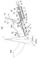
図1は、本発明の第1実施例による放射線照射野限定装置100を示す図である。
放射線照射野限定装置100は、放射線源1から放射される放射線を遮蔽し、放射線の照射野Aを所望の範囲に限定するための装置であって、絞り羽根20と、この絞り羽根20の厚み部分に固定された可撓性を有する線状部材3と、この線状部材3を所定量駆動する駆動部10等とを備えている。
絞り羽根20は、例えば、放射線源1から放射される放射線を遮蔽する適宜の材質(タングステン等)から形成され、その厚さ方向に複数配列されている。また、絞り羽根20は、対向配置された扇形状の絞り羽根20A,20Bを含む。以下、説明の便宜上、絞り羽根20A側に配置された各種部材等を説明するが、この各種部材は、絞り羽根20B側にも同様に配置されている。Hereinafter, the present invention will be described in more detail with reference to the drawings and the like.
(First embodiment)
FIG. 1 is a diagram showing a radiation
The radiation
The
線状部材3の一端は、絞り羽根20Aの外周側の円弧に沿って接線方向に、接続部4を介して固定されている。線状部材3の他端は、駆動部10に接続されている。また、線状部材3は、駆動部10から荷重を受けるときに、容易に座屈を生じることなく、かつ、絞り羽根20Aの円弧に沿って撓むことができる。
このため、線状部材3は、可撓性を有する部材であれば適宜の部材(例えば、連続した金属線であるワイヤ、このワイヤをより合わせたワイヤロープ、その内部が中空であるパイプ等)を用いることができる。One end of the
For this reason, the
また、線状部材3は、絞り羽根20Aの厚み部分に接触しながら絞り羽根20Aを駆動する。そして、線状部材3は、接続部4に固定される前工程において、図1に2点鎖線で示すように、厚み部分との接触部から離れる方向に予備曲げが施され、組み込まれた状態では、厚み部分との接触部をより大きな力で押圧する。これにより、放射線照射野限定装置100は、線状部材3と絞り羽根20Aの厚み部分との接触部における、線状部材3の座屈を防止することができる。 The
駆動部10は、例えば、基台11と、駆動源12と、連結部13と、駆動軸14と、線状部材3が接続された移動子15と、支持軸16等とを備えている。駆動軸14は、駆動源12に連結部13を介して連結されると共に、基台11に挿入されている。
連結部13は、クラッチ機構とトルクリミッタ機構(トルク制限部)とを備えている。
連結部13のクラッチ機構は、機械的接触によって駆動源12の駆動力を駆動軸14に伝達又は遮断する。そして、制御部(不図示)は、絞り羽根を目標位置に移動させるときに、後述するポテンショメータ5、エンコーダ19等(位置検出部)の位置情報から、目標位置に絞り羽根20Aが移動したことを検出した場合に、クラッチ機構を用いて駆動軸14への駆動力の伝達を遮断し、絞り羽根20Aの移動を停止する。これにより、放射線照射野限定装置100は、絞り羽根20Aが目標位置を越えて移動すること、すなわち、絞り羽根20Aのオーバランを防止することができる。つまり、放射線照射野限定装置100は、絞り羽根20Aの移動を短時間で終了させ、絞り羽根20Aの安定した制御、駆動をすることができる。なお、放射線照射野限定装置100は、後述するように、駆動軸14と移動子15とが螺合しているため、クラッチ機構が駆動軸14への駆動力の伝達を遮断した後においても、移動子15の位置を維持することができる。
連結部13のトルクリミッタ機構は、クラッチ機構の機械的接触をばね付勢によって接触させ、駆動軸14に所定以上の負荷が作用したときに、この機械的接触の接触面が滑動するように、ばねの付勢力が調整された過負荷保護機構である。放射線照射野限定装置100は、例えば、対向配置された絞り羽根20A,20Bの内側の側面20A−a,20B−aが接触等して、駆動軸14に所定以上の負荷が作用したときに、このトルクリミッタ機構を作動させることにより、駆動源12等の破損を防止することができる。The
The connecting
The clutch mechanism of the connecting
The torque limiter mechanism of the connecting
駆動軸14は、雄ねじ部14Aを有し、移動子15に形成された雌ねじ部15Aと噛み合っている。
移動子15は、駆動軸14の回転に伴い、駆動軸14の軸線方向に沿って移動する。なお、移動子15は、駆動軸14と所定間隔を隔てて略平行に配置された支持軸16に支持されており、駆動軸14の周方向への回転が規制されている。The
The
また、ローラR1〜R6(線状部材保持部)は、基台11の外側に位置する線状部材3を保持すると共に、この線状部材3の座屈を防止するものであって、線状部材3の軌道を規定している。すなわち、本実施例の放射線照射野限定装置100は、ローラR1〜R6が、絞り羽根20Aと駆動部10との間の線状部材3を軸線方向に移動可能に保持することにより、線状部材3の座屈を防止することができる。
ローラR7〜R9は、絞り羽根20Aを保持するように、絞り羽根20Aの外周面の軌道に沿って、配置されている。The rollers R1 to R6 (linear member holding portions) hold the
The rollers R7 to R9 are arranged along the track of the outer peripheral surface of the
線状部材3は、雄ねじ部14Aと雌ねじ部15Aとの噛み合いにより、駆動軸14の軸線方向に移動する移動子15に接続されているので、この移動子15の移動に伴う荷重が線状部材3に直接伝達され、絞り羽根20が所定量駆動することになる(図2参照)。
具体的には、図1では、移動子15によって線状部材3が基台11に引き込まれ、絞り羽根20Aが照射野Aを広げる方向に引き出された状態を示している。
これに対して、図2は、移動子15によって線状部材3が基台11から押し出され、絞り羽根20Aが照射野Aを狭くする方向に押し出された状態を示している(図中矢印参照)。
また、移動子15に接続された線状部材3の移動量と、駆動軸14の回転角との間には、比例関係が成り立つので、この回転角を高精度で制御することにより、絞り羽根20の駆動量を高精度に制御することができる。Since the
Specifically, FIG. 1 shows a state in which the
On the other hand, FIG. 2 shows a state in which the
In addition, since a proportional relationship is established between the amount of movement of the
ここで、絞り羽根20の駆動量を高精度に制御するために、絞り羽根20の位置を高精度に検出する手段について説明する。放射線照射野限定装置100は、絞り羽根20の位置を検出するためにポテンショメータ5(絶対位置センサ)と、エンコーダ19(相対位置センサ)とを備えている。
ポテンショメータ5は、リニア型ポテンショメータであり、検出バネ5aと、メータ本体5bとを備えている。
検出バネ5aは、絞り羽根20Aの側面に固定された、例えばリン青銅等から形成された板バネである。検出バネ5aは、その一方の端部が後述するメータ本体5bに接している。
メータ本体5bは、所定の電気抵抗を有する材料から形成された部材であり、その放射線源1側の面5cが、放射線源1を中心とした円周面である。メータ本体5bは、この面5cに、検出バネ5aの端部が接触されており、これが絞り羽根20Aの移動に追従して移動する。これに伴い、板バネ5aとメータ本体5bとの電気抵抗は変化する。ポテンショメータ5は、この電気抵抗を測定し、板バネ5aの位置を検出する。絞り羽根20Aの外周面とメータ本体5bの面5cとは、共に放射線源1を中心とした円周面であるため、ポテンショメータ5は、これら円周面の径と板バネ5aの位置とから、絞り羽根20Aの位置を検出することができる。Here, means for detecting the position of the
The
The
The
エンコーダ19は、移動子15の所定の位置からの移動量を測定する検出部であり、駆動軸14の駆動源12と反対側の一端に連結部18を介して設けられている。エンコーダ19は、駆動軸14の回転によって発生するパルスをカウントすることにより、移動子15の移動量を計測する。エンコーダ19は、その分解能として、例えば、駆動軸14の回転毎に256パルスをカウントし、かつ、移動子15が駆動軸14の回転毎に1mm移動するように設定されている場合には、1/256mm(すなわち、3.9μm)の移動子15の移動量を測定することができる。これにより、放射線照射野限定装置100は、線状部材3を駆動させ、さらに、絞り羽根20Aを高精度に制御、駆動することができる。 The
次に、ポテンショメータ5、エンコーダ19等を用いて、絞り羽根20Aの位置を検出、制御する手順の一例について説明する。
制御部(不図示)は、対向配置された絞り羽根20A,20Bの内側の側面20A−a,20B−aを接触させる指示をし、その隙間が無い状態の絞り羽根20Aの基準位置をポテンショメータ5によって検出し、絞り羽根20A及び移動子15の基準位置(所定の位置)を記憶する。次に、制御部は、操作部(不図示)から入力された絞り羽根20Aの目標位置から、絞り羽根20Aの移動量と駆動軸14の回転数とを計算し、この回転数に対応したエンコーダ19の所定のパルス数を計算する。そして、制御部は、駆動源12を駆動して駆動軸14を回転させ、所定のパルス数をカウントしたならば、駆動源12を停止する。例えば、上述の例において、ユーザが目標位置を基準位置から10mmに設定した場合、移動量は10mmとなり、制御部は、駆動軸14を10回転すればよいので、2560パルス(=256パルス×10)カウントするまで、駆動源12を駆動する。これにより、放射線照射野限定装置100は、絞り羽根20Aの絶対位置情報と、移動子15の相対位置情報とに基づいて、絞り羽根20Aの現在位置を高精度に検出することができる。
すなわち、制御部は、ポテンショメータ5により検出された絞り羽根20Aの所定の位置と、目標位置との差を演算し、絞り羽根20Aを目標位置に駆動するために駆動軸14の回転を制御し、絞り羽根20Aを所定量駆動して、放射線の照射野Aを高精度に形成することができる。なお、以上の動作において、制御部は、絞り羽根20Aが目標位置に達したと認識したときに、連結部13のクラッチ機構を用いて駆動軸14への駆動力の伝達を遮断することにより、絞り羽根20Aのオーバランを防止することができる。Next, an example of a procedure for detecting and controlling the position of the
The control unit (not shown) instructs the inner side surfaces 20A-a and 20B-a of the
That is, the control unit calculates the difference between the predetermined position of the
さらに、放射線照射野限定装置100は、絞り羽根20Aの位置を、ポテンショメータ5による絞り羽根20Aの絶対位置情報と、エンコーダ19による絞り羽根20Aの所定の位置からの移動量から計測される位置情報とから、二重に監視することができる。これにより、放射線照射野限定装置100は、これら2つの位置情報に所定量以上の差があった場合に、アラーム信号を放射線照射野限定装置100の制御部に出力することができる。 Further, the radiation
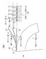
(第2実施例)
図3は、本発明の第2実施例による放射線照射野限定装置100Aを示す斜視図である。図4は、本発明の第2実施例による放射線照射野限定装置100Aを示す正面図である。なお、説明の便宜上、上述した放射線照射野限定装置100と同一部材については同一符号を付し、機能等の説明を適宜省略する。
放射線照射野限定装置100Aは、例えば、その厚さ方向に複数配列された薄い(3〜5mm程度)絞り羽根20A−1〜20A−12と、この絞り羽根20A−1〜20A−12の厚み部分に固定された可撓性を有する線状部材3と、この線状部材3を所定量駆動する複数の駆動ユニット10A〜10C等とを備えている。
駆動ユニット10Aの内部には、複数の移動子15(図1参照)がそれぞれ収容されており、線状部材3A−1〜3A−4をそれぞれ駆動する駆動部が収容されている。同様に、駆動ユニット10B,10Cの内部には、線状部材3B−1〜3B−4,3C−1〜3C−4をそれぞれ駆動する駆動部が収容されている。
なお、線状部材3A−1〜3A−4は、図示のように、軸線方向が略同一であり、同様に、線状部材3B−1〜3B−4、線状部材3C−1〜3C−4の軸線方向も略同一である。これに対して、線状部材3A−1〜3A−4と、線状部材3B−1〜3B−4と、線状部材3C−1〜3C−4とは、互いに軸線方向が異なっている。(Second embodiment)
FIG. 3 is a perspective view showing a radiation
The radiation
A plurality of movers 15 (see FIG. 1) are accommodated in the
The
また、図示のように、線状部材3A−1〜3A−4の一端は、駆動ユニット10Aに接続され、他端は絞り羽根20A−1,20A−4,20A−7,20A−10にそれぞれ接続されている。線状部材3B−1〜3B−4の一端は、駆動ユニット10Bに接続され、他端は絞り羽根20A−2,20A−5,20A−8,20A−11にそれぞれ接続されている。線状部材3C−1〜3C−4の一端は、駆動ユニット10Cに接続され、他端は、絞り羽根20A−3,20A−6,20A−9,20A−12にそれぞれ接続されている。 Further, as shown in the figure, one end of each of the
また、厚さ方向に隣り合う絞り羽根(例えば、絞り羽根20A−1,20A−2)にそれぞれ固定された線状部材3A−1,3B−1は、図示のように、互いに軸線方向が異なる。このために、放射線照射野限定装置100Aでは、厚さ方向に隣り合う絞り羽根を、異なる駆動部で駆動することができるので、駆動部10A〜10Cをある程度大きくして、複数の移動子15を収容することができる。 Further, the
具体的には、絞り羽根20A−1〜20A−12の厚さが5mmの場合には、1つの移動子15の厚さが15mm必要であるので、移動子15に接続された線状部材3を、3つの絞り羽根毎に絞り羽根に接続した。すなわち、放射線照射野限定装置100Aでは、上述したように、駆動ユニット10A〜10Cを所定間隔を隔てて配置することができるので、絞り羽根20A−1〜20A−12を薄くしても、厚さ方向に隣り合う絞り羽根を、耐久性のある駆動部で駆動することができる。 Specifically, when the thickness of the
したがって、放射線照射野限定装置100Aによれば、線状部材3A−1〜3A−4、3B−1〜3B−4、3C−1〜3C−4の軸線方向毎に、複数の駆動ユニット10A〜10Cを所定間隔を隔てて配置することができ、さらに、1つの駆動ユニット(例えば、駆動ユニット10A)で厚さ方向に隣り合った絞り羽根(例えば、絞り羽根20A−1,20A−2)を駆動する必要がないので、駆動ユニット10A〜10Cをある程度大きくすることができ、その結果、低コスト化を図ると共に、駆動ユニット10A〜10Cの耐久性を維持することができる。 Therefore, according to the radiation irradiation
以上説明したように、本実施例の放射線照射野限定装置100Aは、厚さ方向に隣り合う絞り羽根20A(絞り羽根20A−1,20A−4,20A−7,20A−10、絞り羽根20A−2,20A−5,20A−8,20A−11、絞り羽根20A−3,20A−6,20A−9,20A−12)にそれぞれ固定された線状部材3(3A−1〜3A−4,3B−1〜3B−4,3C−1〜3C−4)が、互いに軸線方向が異なり、また、その軸線方向が、所定数毎(本実施例では3つ)に同一になる。そして、3つの駆動ユニット10A,10B,10Cは、軸線方向が所定数毎に同一となる線状部材をそれぞれ駆動する駆動部を、その内部にそれぞれ収容している。これにより、放射線照射野限定装置100Aは、線状部材3の軸線方向毎に駆動部を配置し、さらに、これらの駆動部を収容する駆動ユニット10A,10B,10Cを線状部材3の軸線方向毎に備えることにより、駆動部を煩雑にすることなく収容することができる。 As described above, the radiation
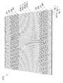
(第3実施例)
図5は、本発明の第3実施例による絞り羽根20Aを示す図である(第1実施例を示す図1のD−D部断面図に相当する。)。
絞り羽根20Aは、転動体を介して互いに移動自在に厚さ方向に配列された絞り羽根からなる。以下、絞り羽根20A−1〜20A−4について説明するが、図示のように、絞り羽根20A−1〜20A−4の形状を1つのパターンとして捉えると、絞り羽根20Aは、絞り羽根20A−1〜20A−4を繰り返し厚さ方向に配列することにより形成される(後述)。
絞り羽根20A−1〜20A−4は、転動体21〜28を介して互いに移動自在に厚さ方向に配列されている。絞り羽根20A−1〜20A−4の側面は、図示のように、転動体21〜28を保持する保持部を形成するように厚さ方向に突出しており、これにより、絞り羽根20A−1〜20A−4が駆動され、隙間が生じる場合であっても、強力な放射線が絞り羽根20A−1〜20A−4間を通過してしまうことを防止できる。すなわち、この保持部は、転動体21〜28を保持すると同時に、放射線を遮蔽する遮蔽部である。
さらに、保持部を形成する絞り羽根20A−1〜20A−4の厚さと、転動体21〜28の大きさとを所定値にすることにより、絞り羽根20A−1〜20A−4の強度を所定値以上に保つことができる。(Third embodiment)
FIG. 5 is a view showing a
The
The
Furthermore, the strength of the
転動体21〜28は、絞り羽根20A−1〜20A−4が線状部材3A−1,3B−1,3C−1,3A−2によってそれぞれ駆動されるときに、いわゆる軸受の機能を有するのであれば、適宜の形状(例えば、ボール形状、円筒状、円錐台形状)であってもよい。
また、転動体21〜24は、転動体25〜28よりも放射線源1に近い位置に配置されており、転動体21〜24の径は、転動体25〜28の径よりも小さい。これにより、複数の絞り羽根20A−1〜20A−4は、線状部材3A−1,3B−1,3C−1,3A−2によって、滑らかに駆動される。The rolling
Moreover, the rolling elements 21-24 are arrange | positioned in the position near the
ここで、1つの絞り羽根(例えば、絞り羽根20A−1)を隔てて隣り合う転動体23,24と転動体27,28との配置について説明する。
転動体23は、放射線源1に近い位置に配置され、転動体24は放射線源1から離れた位置に配置されており、同様に、転動体27は、放射線源1に近い位置に配置され、転動体28は放射線源1から離れた位置に配置されている。
したがって、絞り羽根20Aの全体の厚さは、転動体21〜28の大きさによって変化することがなく、例えば、絞り羽根20A−1の厚さと略同一の径を有する転動体を保持部で保持することもできる。さらに、転動体23,27により、絞り羽根20A−1,20A−2間の隙間が略均一に保たれるので、絞り羽根20A−1,20A−2が接触して、摩擦抵抗が大きくなり、例えば、線状部材3、駆動部10等に過大な負荷がかかることを防止できる。Here, the arrangement of the rolling
The rolling element 23 is disposed at a position close to the
Therefore, the entire thickness of the
また、保持部は、絞り羽根20A−1〜20A−4を曲げ加工又は切削加工することで形成される直線及び/又は曲線からなり、その結果、絞り羽根20A−1〜20A−4を薄くしても保持部を形成することができる。
保持部は、図示のように、放射線の放射方向(図1参照)に対して異なる位置に配置されているが、絞り羽根20A−1〜20A−4の所定数毎(ここでは、4つ)に、繰り返し同一の位置となる。したがって、この絞り羽根20Aは、所定数毎に同一形状の絞り羽根を繰り返し配列することで保持部を形成することができ、その結果、絞り羽根20Aを形成する場合に、曲げ加工又は切削加工の種類を所定数にすることができ、低コスト化、迅速化を図ることができる。Further, the holding portion is formed of a straight line and / or a curve formed by bending or cutting the
As shown in the drawing, the holding portions are arranged at different positions with respect to the radiation direction of radiation (see FIG. 1), but for each predetermined number (here, four) of the
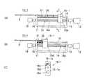
(第4実施例)
図6は、本発明の第4実施例による駆動部10−1を示す図である。なお、上述した駆動部10と同一部材については、その機能等の説明を適宜省略する。
駆動部10−1は、上述した駆動部10に比べて、例えば、基台11に収容された移動子15−1と、ガイド31と、弾性部材32(ここでは、コイルバネ)等とを備えた点が異なる。
移動子15−1は、駆動軸14の回転に伴って駆動軸14の軸線方向を移動可能であって、台座部15−1aと、この台座部15−1aと係合する係合部15−1bとからなり、台座部15−1aは、駆動軸14の雄ねじ部14Aと噛み合う雌ねじ部15Aと、支持軸16が貫通する支持孔15Bと、線状部材3が接続された接合部15Cとを有している。
ガイド31は、支持軸16に支持されると共に、支持軸16の軸線方向に移動可能であって、線状部材3の形状を保持する。このガイド31間には、支持軸16に支持された弾性部材32が配置されている。(Fourth embodiment)
FIG. 6 is a diagram illustrating a driving unit 10-1 according to a fourth embodiment of the present invention. In addition, about the same member as the
Compared with the
The mover 15-1 can move in the axial direction of the
The
図中(A)は、移動子15−1によって線状部材3が基台11に引き込まれた状態(すなわち、絞り羽根20Aが照射野Aを広げる方向に引き出された状態)を示している。この場合に、駆動部10(図1参照)においては、線状部材3が基台11内でフリーとなるために、この状態から移動子15が線状部材3を基台11の外に押し出すときに、線状部
材3に座屈が発生する可能性がある。In the figure, (A) shows a state in which the
これに対して、本実施例における駆動部10−1は、基台11内での線状部材3の座屈を防止するために、上述したように、支持軸16に支持された複数のガイド31と、ガイド31間に配置した弾性部材32とを備え、弾性部材32は、複数のガイド31が支持軸16の軸線方向を移動した場合であっても複数のガイド31間の間隔を略同一に保つことができる。
また、ガイド31間の間隔は、弾性部材32の長さによって規定される。なお、弾性部材32は、複数のガイド31間の間隔を略同一に保つことができるのであれば、コイルバネに限らず適宜種類のものを適用することができる。On the other hand, as described above, the drive unit 10-1 in the present embodiment has a plurality of guides supported by the
Further, the interval between the
図中(B)は、移動子15−1によって線状部材3が基台11から押し出された状態(すなわち、絞り羽根20Aが照射野Aを狭くする方向に押し出された状態)を示している。この場合には、線状部材3が基台11内でフリーとなる部分が小さく、さらに、ガイド31間に設けられた弾性部材32が縮んでいるので、ガイド31間の間隔が小さくなり、線状部材3の座屈を確実に防止することができる。 (B) in the figure shows a state in which the
(第5実施例)
図7は、本発明の第5実施例による放射線照射野限定装置100Bを示す図である。
この放射線照射野限定装置100Bは、上述した第1実施例の放射線照射野限定装置100に比べて、線状部材3の一端が、略矩形である絞り羽根40(ここでは、絞り羽根40A)の外周側の形状に沿った接線方向に、接続部4を介して固定されている点が異なる。
線状部材3の他端は、駆動部10に収容された移動子15に接続されている。この略矩形の絞り羽根40Aは、この移動子15の移動に伴って、ローラR5,R7,R8により案内される軌道を所定量駆動される。
すなわち、この放射線照射野限定装置100Bによれば、絞り羽根40Aが略矩形であっても、絞り羽根40Aに可撓性を有する線状部材3を固定することにより、絞り羽根40Aを軌道に沿って高精度に駆動できる。(5th Example)
FIG. 7 is a view showing a radiation
In this radiation
The other end of the
In other words, according to this radiation irradiation
(変形例)
以上説明した実施例に限定されることなく、種々の変形や変更が可能であって、それらも本発明の均等の範囲内である。
(1)上述した駆動部10,10−1では、駆動源12に連結された駆動軸14に形成された雄ねじ部14Aと、移動子15の雌ねじ部15Aとが噛み合うことにより、移動子15を駆動軸14の軸線方向に駆動するようにしていたが、これに限られず、駆動源12の駆動力を移動子15に伝達できるのであれば、適宜の方式(例えば、油圧機構、空圧機構等を用いて移動子15を駆動する方式)を用いてもよい。(Modification)
The present invention is not limited to the embodiments described above, and various modifications and changes are possible, and these are also within the equivalent scope of the present invention.
(1) In the
(2)上述した駆動部10,10−1では、1つの駆動源12を用いて1つの駆動軸14を駆動するようにしていたが、これに限られず、1つの駆動源により複数の駆動軸14を適宜駆動するようにしてもよい。
具体的には、1つの駆動源に接続された回転軸に、各駆動軸14の位置に合わせたプーリ(又は、歯車)等を設け、さらに、各駆動軸14の一端に、このプーリに連動するベルト(又は、この回転軸に設けられた歯車に噛み合う歯車)等を設ける。これにより、1つの駆動源の駆動力を、プーリ、歯車等を介して、各駆動軸14に伝達することができる。
ここで、放射線治療を行う被検者の病巣部に対して放射線を照射する場合には、この病巣部の形状に合わせた放射線の照射野を短時間で高精度に形成する必要があり、そのために、複数配列された絞り羽根20,40毎に要求される駆動量が異なることになる。
したがって、連結部13のクラッチ機構を、絞り羽根20,40毎に制御する制御部を設け、この制御部は、上述した絞り羽根20,40及び/又は移動子15の絶対位置情報と、移動子15の相対位置情報とに基づいて、各絞り羽根20,40毎に要求される各駆動軸14の駆動量と、この駆動量に応じたクラッチ機構による1つの駆動源の駆動力の伝達時間とを演算する。これにより、この制御部によれば、複数配列された絞り羽根20,40に対応する各駆動軸14の駆動量に応じて、この1つの駆動源の駆動力を各駆動軸14に必要な時間だけ伝達することができ、その結果、1つの駆動源で複数の駆動軸14を高精度に制御できると共に、放射線の照射野を短時間で高精度に形成できる。
さらに、駆動軸14毎に異なる駆動源12を配置する必要がないので、設置スペースに余裕ができ、ある程度の大きさを有する駆動源(例えば、耐摩耗性が高く、トルクの大きい駆動源であって、サーボモータ、パルスモータ、ブラシレスDCモータ等)を適用することができる。(2) In the
Specifically, pulleys (or gears) or the like that match the position of each
Here, when irradiating the lesion part of the subject undergoing radiotherapy, it is necessary to form a radiation field that matches the shape of the lesion part with high accuracy in a short time. In addition, the required drive amount differs for each of the plurality of
Therefore, a control unit that controls the clutch mechanism of the connecting
Furthermore, since it is not necessary to arrange
(3)絞り羽根20Aでは、転動体21〜24を絞り羽根20A上の放射線源1に近い位置に配置し、転動体25〜28を放射線源1から離れた位置に配置したが、絞り羽根20Aを互いに移動自在に配列することができるのであれば、転動体の数及び位置は、これに限られず、適宜の数の転動体を介在するようにしてもよく、さらに、転動体21〜24の位置と転動体25〜28の位置との略中間の位置に他の転動体を配置してもよい。(3) In the
(4)上述した放射線照射野限定装置100では、線状部材3の一端が絞り羽根20Aの外周側に固定されるように駆動部10を配置したが、絞り羽根20Aを駆動できるのであれば、線状部材3の一端が絞り羽根20Aの内周側に固定されるように配置してもよい。(4) In the radiation irradiation
(5)絞り羽根20,40の形状は、それぞれ扇形、略矩形としたが、上述した線状部材3に接続可能であって、この線状部材3の移動に伴って放射線源1から放射される放射線を遮蔽するように移動できるのであれば、適宜の形状であってもよい。(5) Although the shape of the
(6)第1実施例において、ポテンショメータ5は、絞り羽根20Aの外周の絶対位置を直接測定する例を示したが、これに限定されない。例えば、図1、図2に示すように、駆動部10にポテンショメータ17(2点鎖線で示す。)を設け、駆動子15の変位を測定し、線状部材3の移動量から、絞り羽根20Aの位置を測定してもよい。
さらに、第2実施例のように、駆動部を線状部材3の軸線方向毎に設けることにより、放射線照射野限定装置は、ポテンショメータに必要な厚みを確保することできる(例えば、絞り羽根20Aの厚みが3mm、線状部材3の軸線方向が3方向の場合、ポテンショメータ17の厚みは、9mmまでとすることができる。)。また、絞り羽根20Aの厚さを薄く設定した場合にも、ポテンショメータ17は、必要な厚みを維持することができる(例えば、前述の例において、絞り羽根20Aの厚みが1mmに設定されても、ポテンショメータ17の厚みは、3mmまでとすることができる)。(6) In the first embodiment, the
Furthermore, as in the second embodiment, by providing the driving unit for each axial direction of the
(7)第1実施例において、放射線照射野限定装置100は、エンコーダ19(相対位置センサ)により移動子15の移動量を測定し、絞り羽根20Aを高精度に制御、駆動する例を示したが、これに限定されない。例えば、リニア型のエンコーダを用いて、絞り羽根20Aの基準位置(所定の位置)からの移動量を測定しもよい。これによっても、放射線照射野限定装置100は、絞り羽根20Aを高精度に制御、駆動することができる(7) In the first embodiment, the radiation
(8)第2実施例において、駆動部は、移動子15を備えている例を示したが、これに限定されない。駆動部が必要な厚みを確保でき、また、線状部材3をその軸線方向に駆動できればよいので、放射線照射野限定装置は、例えばラックとピニオンギア等の機構を備えてもよい。この場合、駆動部は、ラックとピニオンギアとの間にギャップがあるときにも、ポテンショメータ等を用いることにより、絞り羽根を高精度に駆動することができる。また、駆動部は、ピニオンギアの回転軸に、駆動力制限部(例えばボール及びボールポケット方式のトルクリミッタ)を設けることにより、駆動源等の破損を防止することができる。(8) In the second embodiment, an example in which the drive unit includes the
(9)各実施例において、駆動部は、駆動軸14と移動子15とをねじ結合させて、絞り羽根を駆動させた例を示したが、これに限定されない。例えば、絞り羽根20の厚みが大きく、重量が大きいときには、駆動軸14と移動子15とを、ボールねじによって結合させてもよい。これにより、駆動部は、駆動軸14を円滑に回転させることができ、絞り羽根20の重量が大きいときにも、その安定した駆動をすることができる。(9) In each embodiment, the drive unit has shown an example in which the
(10)第1実施例において、エンコーダとしては、回転軸14の回転数を計測するためのエンコーダ19のみが設けられた例を示したが、これに限定されない。例えば、エンコーダ19の他に駆動源12の回転数を計測するために駆動源測定用エンコーダを設ける。そして、トルクリミッタ機構が作動している状態では、駆動軸14の回転数と駆動源の回転数とは、差異が生じるため、制御部にエンコーダ19との駆動源測定用エンコーダの出力を監視させ、それらの回転数に差異があった場合に、駆動源を停止させてもよい。これにより、機械式のトルクリミッタ(トルク制限部)を用いている場合に、その接触面の磨耗を防止することができる。また、放射線照射野限定装置は、モータ(駆動源)の高負荷状態における長時間の駆動を防止でき、その破損を防止することができる。
(10) In the first embodiment, an example in which only the
Claims (22)
Translated fromJapanese前記絞り羽根の厚み部分に固定され、また、前記絞り羽根の前記放射線源側又は前記照射野側の側面に沿って撓むことができるように設けられた可撓性を有する線状部材と、
前記線状部材を駆動する駆動部と、
を備えた放射線照射野限定装置。In the radiation field limiting device that blocks the radiation emitted from the radiation source by driving a predetermined amount of the diaphragm blades arranged in the thickness direction, and limits the radiation field of the radiation to a desired range,
A linear member having flexibility, which is fixed to a thickness portion of the diaphragm blades and provided so as to be able to bend along a side surface of the diaphragm blades on the radiation source side or the irradiation field side;
A drive unit for driving the linear member;
Radiation field limited device equipped with.
前記駆動部は、
基台と、
駆動源に連結部を介して連結され、前記基台に挿入された駆動軸と、
前記駆動軸の回転に伴い、前記駆動軸の軸線方向に沿って移動すると共に、前記線状部材が接続された移動子と、
を備えた放射線照射野限定装置。In the radiation field limiting device according to claim 1,
The drive unit is
The base,
A drive shaft connected to a drive source via a connecting portion and inserted into the base;
As the drive shaft rotates, the mover moves along the axial direction of the drive shaft, and the linear member is connected,
Radiation field limited device equipped with.
前記連結部は、所定以上のトルクの伝達を制限するトルク制限部を備えること、
を特徴とする放射線照射野限定装置。In the irradiation field limiting device according to claim 2,
The connecting portion includes a torque limiting portion that limits transmission of torque equal to or greater than a predetermined value;
An irradiation field limiting device characterized by.
前記連結部は、前記駆動軸への駆動力を伝達又は遮断するクラッチ機構を備えること、
前記トルク制限部が所定の時間、作動した場合に、前記クラッチ機構を用いて前記駆動軸への前記駆動力の伝達を遮断する制御部を備えること、
を特徴とする放射線照射野限定装置。In the irradiation field limiting device according to claim 3,
The connecting portion includes a clutch mechanism for transmitting or interrupting a driving force to the driving shaft;
A control unit configured to block transmission of the driving force to the drive shaft using the clutch mechanism when the torque limiting unit is activated for a predetermined time;
An irradiation field limiting device characterized by.
前記連結部は、前記駆動軸への駆動力を伝達又は遮断するクラッチ機構を備えること、
前記絞り羽根の位置を検出する位置検出部を備えること、
前記絞り羽根を目標位置に移動させるときに、前記位置検出部が前記目標位置に前記絞り羽根が移動したことを検出した場合に、前記クラッチ機構を用いて前記駆動軸への前記駆動力の伝達を遮断し、前記絞り羽根の移動を停止する制御部を備えること、
を特徴とする放射線照射野限定装置。In the irradiation field limiting device according to claim 2,
The connecting portion includes a clutch mechanism for transmitting or interrupting a driving force to the driving shaft;
Comprising a position detector for detecting the position of the aperture blade;
When the position detecting unit detects that the diaphragm blade has moved to the target position when the diaphragm blade is moved to the target position, the driving force is transmitted to the drive shaft using the clutch mechanism. And a control unit that stops the movement of the diaphragm blades,
An irradiation field limiting device characterized by.
前記駆動源の駆動力を複数の前記駆動軸へ伝達する駆動力伝達部と、
複数の前記駆動軸への前記駆動力を伝達又は遮断する複数のクラッチ機構と、
複数の前記クラッチ機構をそれぞれ制御し、前記駆動源の前記駆動力を前記駆動軸毎に伝達し、複数の前記絞り羽根をそれぞれ駆動可能な制御部とを備えること、
を特徴とする放射線照射野限定装置。In the irradiation field limiting device according to claim 2,
A driving force transmission unit that transmits the driving force of the driving source to the plurality of driving shafts;
A plurality of clutch mechanisms for transmitting or blocking the driving force to the plurality of driving shafts;
A control unit that controls each of the plurality of clutch mechanisms, transmits the driving force of the driving source to each driving shaft, and can drive the plurality of diaphragm blades, respectively.
An irradiation field limiting device characterized by.
前記移動子は、雌ねじ部を有し、
前記駆動軸は、前記雌ねじ部と噛み合う雄ねじ部を有し、回転駆動されることにより前記移動子を前記駆動軸の前記軸線方向に移動させること、
を特徴とする放射線照射野限定装置。In the radiation irradiation field limiting device according to claim 2,
The moving element has a female screw part,
The drive shaft has a male screw portion that meshes with the female screw portion, and is rotated to move the moving element in the axial direction of the drive shaft.
An irradiation field limiting device characterized by.
前記絞り羽根は、扇形又は略矩形であること、
を特徴とする放射線照射野限定装置。In the radiation field limiting device according to claim 1,
The aperture blades are fan-shaped or substantially rectangular;
An irradiation field limiting device characterized by.
前記線状部材は、連続した金属線、前記金属線をより合わせたロープ、その内部が中空である管のいずれかであること、
を特徴とする放射線照射野限定装置。In the radiation field limiting device according to claim 1,
The linear member is any one of a continuous metal wire, a rope obtained by combining the metal wires, and a tube having a hollow inside,
An irradiation field limiting device characterized by.
前記基台に設けられ、前記駆動軸と所定間隔を隔てて略平行に配置された支持軸と、
前記支持軸にその軸線方向に移動可能に支持され、前記線状部材の形状を保持する少なくとも1つのガイドと、
前記ガイド間に配置され、ガイド間の間隔を略同一にする弾性部材と、
を備えた放射線照射野限定装置。In the irradiation field limiting device according to claim 2,
A support shaft provided on the base and disposed substantially parallel to the drive shaft at a predetermined interval;
At least one guide which is supported by the support shaft so as to be movable in the axial direction thereof and holds the shape of the linear member;
An elastic member disposed between the guides and having substantially the same distance between the guides;
Radiation field limited device equipped with.
前記絞り羽根及び/又は前記移動子の絶対位置を測定する絶対位置センサと、
前記絶対位置センサにより測定された前記絞り羽根及び/又は前記移動子の所定の位置からの移動量を測定する高分解能の相対位置センサとを備えること、
を特徴とする放射線照射野限定装置。In the irradiation field limiting device according to claim 2,
An absolute position sensor for measuring an absolute position of the diaphragm blade and / or the moving element;
A high-resolution relative position sensor that measures the amount of movement of the diaphragm blade and / or the moving element from a predetermined position measured by the absolute position sensor;
An irradiation field limiting device characterized by.
複数の前記絞り羽根は、転動体を介して互いに移動自在に厚さ方向に配列され、
前記絞り羽根の側面は、前記転動体を保持する保持部を形成するように前記厚さ方向に突出していること、
を特徴とする放射線照射野限定装置。In the radiation field limiting device according to claim 1,
The plurality of diaphragm blades are arranged in the thickness direction so as to be movable with respect to each other via rolling elements,
A side surface of the diaphragm blade protrudes in the thickness direction so as to form a holding portion for holding the rolling element;
An irradiation field limiting device characterized by.
前記保持部は、前記転動体を保持するように直線及び/又は曲線からなること、
を特徴とする放射線照射野限定装置。In the irradiation field limiting device according to claim 12,
The holding part is composed of a straight line and / or a curve so as to hold the rolling element;
An irradiation field limiting device characterized by.
前記絞り羽根を隔てて隣り合う前記転動体は、一方が前記放射線源に近い位置に配置され、他方が前記放射線源から離れた位置に配置されること、
を特徴とする放射線照射野限定装置。In the irradiation field limiting device according to claim 12,
One of the rolling elements adjacent to each other across the diaphragm blades is disposed at a position close to the radiation source, and the other is disposed at a position away from the radiation source.
An irradiation field limiting device characterized by.
前記保持部は、前記放射線の放射方向に対して異なる位置に配置され、
前記絞り羽根の所定数毎に、繰り返し同一の位置となること、
を特徴とする放射線照射野限定装置。In the irradiation field limiting device according to claim 12,
The holding part is arranged at a different position with respect to the radiation direction of the radiation,
For every predetermined number of the aperture blades, repeatedly become the same position,
An irradiation field limiting device characterized by.
前記保持部は、隣り合う前記絞り羽根間を、通過する放射線を遮蔽する遮蔽部であること、
を特徴とする放射線照射野限定装置。In the irradiation field limiting device according to claim 12,
The holding part is a shielding part that shields radiation passing between adjacent diaphragm blades;
An irradiation field limiting device characterized by.
隣り合う前記絞り羽根間の隙間に、放射線を遮蔽する遮蔽部を有すること、
を特徴とする放射線照射野限定装置。In the radiation field limiting device according to claim 1,
Having a shielding part that shields radiation in a gap between adjacent diaphragm blades;
An irradiation field limiting device characterized by.
厚さ方向に隣り合う前記絞り羽根にそれぞれ固定された前記線状部材は、互いに軸線方向が異なること、
を特徴とする放射線照射野限定装置。In the radiation field limiting device according to claim 1,
The linear members respectively fixed to the diaphragm blades adjacent in the thickness direction have different axial directions from each other;
An irradiation field limiting device characterized by.
前記駆動部は、前記線状部材の軸線方向が所定数毎に同一となる前記絞り羽根を駆動すること、
を特徴とする放射線照射野限定装置。In the radiation field limiting device according to claim 18,
The drive unit drives the diaphragm blades in which the axial direction of the linear member is the same every predetermined number;
An irradiation field limiting device characterized by.
前記絞り羽根の厚み部分に固定された可撓性を有する線状部材と、
前記線状部材を駆動する駆動部とを備え、
厚さ方向に隣り合う前記絞り羽根にそれぞれ固定された前記線状部材は、互いに軸線方向が異なり、その軸線方向が所定数毎に同一になり、
前記軸線方向が所定数毎に同一となる前記線状部材を、それぞれ駆動する前記駆動部を複数収容した駆動ユニットを複数備えること、
を特徴とする放射線照射野限定装置。In the radiation field limiting device that blocks the radiation emitted from the radiation source by driving a predetermined amount of the diaphragm blades arranged in the thickness direction, and limits the radiation field of the radiation to a desired range,
A flexible linear member fixed to the thickness portion of the diaphragm blade;
A drive unit for driving the linear member,
The linear members fixed to the diaphragm blades adjacent to each other in the thickness direction are different from each other in the axial direction, and the axial direction is the same every predetermined number,
A plurality of drive units each containing a plurality of the drive units for driving the linear members having the same axial direction every predetermined number;
An irradiation field limiting device characterized by.
前記絞り羽根と前記駆動部との間の前記線状部材を軸線方向に移動可能に保持して、前記線状部材の座屈を防止する線状部材保持部を備えること、
を特徴とする放射線照射野限定装置。In the radiation field limiting device according to claim 1,
A linear member holding unit that holds the linear member between the diaphragm blade and the drive unit so as to be movable in the axial direction and prevents buckling of the linear member;
An irradiation field limiting device characterized by.
前記線状部材は、前記絞り羽根をその厚み部分に接触しながら駆動し、その接触部から離れる方向に予備曲げが施され、前記厚み部分に接している部分を押圧することにより、その座屈防止がされること、
を特徴とする放射線照射野限定装置。In the radiation field limiting device according to claim 1,
The linear member is driven while the diaphragm blades are in contact with the thickness portion, pre-bent in a direction away from the contact portion, and pressed on the portion in contact with the thickness portion, thereby buckling the linear member. Being prevented,
An irradiation field limiting device characterized by.
Applications Claiming Priority (3)
| Application Number | Priority Date | Filing Date | Title |
|---|---|---|---|
| JP2004005922 | 2004-01-13 | ||
| JP2004005922 | 2004-01-13 | ||
| PCT/JP2005/000294WO2005068019A1 (en) | 2004-01-13 | 2005-01-13 | Device for limiting field on which raddiation is irradiated |
Publications (2)
| Publication Number | Publication Date |
|---|---|
| JPWO2005068019A1 JPWO2005068019A1 (en) | 2008-04-24 |
| JP4642660B2true JP4642660B2 (en) | 2011-03-02 |
Family
ID=34792119
Family Applications (1)
| Application Number | Title | Priority Date | Filing Date |
|---|---|---|---|
| JP2005517053AExpired - Fee RelatedJP4642660B2 (en) | 2004-01-13 | 2005-01-13 | Radiation field limited device |
Country Status (5)
| Country | Link |
|---|---|
| US (1) | US7965819B2 (en) |
| EP (1) | EP1712254B1 (en) |
| JP (1) | JP4642660B2 (en) |
| DE (1) | DE602005014539D1 (en) |
| WO (1) | WO2005068019A1 (en) |
Families Citing this family (24)
| Publication number | Priority date | Publication date | Assignee | Title |
|---|---|---|---|---|
| DE102006039793B3 (en)* | 2006-08-24 | 2008-01-24 | Siemens Ag | Motor-controlled parallel plate collimator for x-ray apparatus, has position measurement potentiometer fitted to each plate |
| JP2008229324A (en)* | 2007-02-23 | 2008-10-02 | Toshiba Corp | Radiation therapy equipment |
| US8017915B2 (en) | 2008-03-14 | 2011-09-13 | Reflexion Medical, Inc. | Method and apparatus for emission guided radiation therapy |
| US8938051B2 (en)* | 2008-04-21 | 2015-01-20 | Elekta Ab (Publ) | Multi-leaf collimators |
| JP5027067B2 (en)* | 2008-06-27 | 2012-09-19 | 三菱電機株式会社 | Multi-leaf collimator for particle beam therapy system |
| JP2011136038A (en)* | 2009-12-28 | 2011-07-14 | Right Manufacturing Co Ltd | Apparatus for limiting irradiation field, and linear-member driving device |
| US9283403B2 (en) | 2011-03-31 | 2016-03-15 | Reflexion Medical, Inc. | Systems and methods for use in emission guided radiation therapy |
| FI125341B (en)* | 2012-07-09 | 2015-08-31 | Beneq Oy | Apparatus and method for processing substrates |
| US10367403B2 (en)* | 2014-08-21 | 2019-07-30 | General Electric Company | Systems and methods for independent motion of parallel actuators |
| EP3308381A4 (en) | 2015-06-10 | 2019-04-17 | RefleXion Medical Inc. | DESIGN OF BINARY MULTILAYER COLLATORS WITH HIGH BANDWIDTH |
| WO2017041750A1 (en) | 2015-09-10 | 2017-03-16 | Shanghai United Imaging Healthcare Co., Ltd. | Multi-leaf collimator and driving system |
| WO2017156316A1 (en) | 2016-03-09 | 2017-09-14 | Reflexion Medical, Inc. | Fluence map generation methods for radiotherapy |
| US10695586B2 (en) | 2016-11-15 | 2020-06-30 | Reflexion Medical, Inc. | System for emission-guided high-energy photon delivery |
| EP4464251A3 (en) | 2016-11-15 | 2025-02-19 | RefleXion Medical, Inc. | Radiation therapy patient platform |
| WO2018093849A1 (en) | 2016-11-15 | 2018-05-24 | Reflexion Medical, Inc. | Methods for radiation delivery in emission-guided radiotherapy |
| WO2018183748A1 (en) | 2017-03-30 | 2018-10-04 | Reflexion Medical, Inc. | Radiation therapy systems and methods with tumor tracking |
| EP4342521A3 (en) | 2017-07-11 | 2024-05-08 | RefleXion Medical Inc. | Methods for pet detector afterglow management |
| EP4592713A2 (en) | 2017-08-09 | 2025-07-30 | RefleXion Medical, Inc. | Systems and methods for fault detection in emission-guided radiotherapy |
| WO2019099551A1 (en) | 2017-11-14 | 2019-05-23 | Reflexion Medical, Inc. | Systems and methods for patient monitoring for radiotherapy |
| CN107769483B (en)* | 2017-11-22 | 2019-09-27 | 清华大学 | A Dual Sensor Feedback and Drive System for Linear Motors |
| CN109173080B (en) | 2018-07-23 | 2021-03-23 | 上海联影医疗科技股份有限公司 | Device and method for hybrid driving of grating blade |
| US10892064B2 (en) | 2018-12-05 | 2021-01-12 | Shanghai United Imaging Healthcare Co., Ltd. | Multi-leaf collimator |
| JP7482693B2 (en)* | 2020-06-09 | 2024-05-14 | 富士フイルムヘルスケア株式会社 | X-ray image diagnostic apparatus and method of operating same |
| KR102752687B1 (en)* | 2023-06-30 | 2025-01-10 | 오스템임플란트 주식회사 | X-ray imaging apparatus |
Citations (8)
| Publication number | Priority date | Publication date | Assignee | Title |
|---|---|---|---|---|
| JPS59191869U (en)* | 1983-06-06 | 1984-12-19 | 日産自動車株式会社 | Drive source unit |
| JPS62136338A (en)* | 1985-12-03 | 1987-06-19 | Daihatsu Motor Co Ltd | Torque limitter of spindle head |
| JPH03143455A (en)* | 1989-10-31 | 1991-06-19 | Toshiba Corp | Multi-divided profiling apparatus |
| JPH03268771A (en)* | 1990-03-20 | 1991-11-29 | Mitsubishi Electric Corp | Radioactive ray radiation field limiting device |
| JPH07204284A (en)* | 1994-01-11 | 1995-08-08 | Hitachi Medical Corp | Multi-divided diaphragm driving mechanism for radiation treatment device |
| JP2002186677A (en)* | 2000-12-22 | 2002-07-02 | Toshiba Corp | Radiation therapy device and micro multi-leaf collimator |
| JP2002242968A (en)* | 2001-02-15 | 2002-08-28 | Honda Motor Co Ltd | Electric parking brake device |
| JP2002355242A (en)* | 2000-12-19 | 2002-12-10 | Ge Medical Systems Global Technology Co Llc | Adjustable collimeter |
Family Cites Families (9)
| Publication number | Priority date | Publication date | Assignee | Title |
|---|---|---|---|---|
| JPS59191869A (en) | 1983-04-15 | 1984-10-31 | 株式会社日立製作所 | Damper device for refrigerator |
| JPH06300896A (en) | 1993-04-13 | 1994-10-28 | Hitachi Medical Corp | Drive mechanism for multisplit collimater device for radiotherapy equipment |
| JP2529523B2 (en) | 1993-06-23 | 1996-08-28 | メカテック株式会社 | Transfer equipment |
| DE19536804A1 (en) | 1995-10-02 | 1997-04-03 | Deutsches Krebsforsch | Contour collimator for radiation therapy |
| JPH09131411A (en) | 1995-11-09 | 1997-05-20 | Mitsubishi Electric Corp | X-ray irradiation tube |
| JP2002210026A (en) | 2001-01-19 | 2002-07-30 | Toshiba Corp | Radiation therapy device and radiation field setting aperture device |
| JP2003093524A (en) | 2001-09-25 | 2003-04-02 | Mitsubishi Electric Corp | Radiation therapy system |
| JP2004089214A (en) | 2002-08-29 | 2004-03-25 | Natl Inst Of Radiological Sciences | Pneumatic cylinder driven multi-leaf collimator |
| JP4184839B2 (en) | 2003-03-13 | 2008-11-19 | 株式会社東芝 | Multi-segment diaphragm device |
- 2005
- 2005-01-13JPJP2005517053Apatent/JP4642660B2/ennot_activeExpired - Fee Related
- 2005-01-13DEDE602005014539Tpatent/DE602005014539D1/ennot_activeExpired - Lifetime
- 2005-01-13WOPCT/JP2005/000294patent/WO2005068019A1/enactiveApplication Filing
- 2005-01-13EPEP05703533Apatent/EP1712254B1/ennot_activeExpired - Lifetime
- 2005-01-13USUS10/585,919patent/US7965819B2/ennot_activeExpired - Fee Related
Patent Citations (8)
| Publication number | Priority date | Publication date | Assignee | Title |
|---|---|---|---|---|
| JPS59191869U (en)* | 1983-06-06 | 1984-12-19 | 日産自動車株式会社 | Drive source unit |
| JPS62136338A (en)* | 1985-12-03 | 1987-06-19 | Daihatsu Motor Co Ltd | Torque limitter of spindle head |
| JPH03143455A (en)* | 1989-10-31 | 1991-06-19 | Toshiba Corp | Multi-divided profiling apparatus |
| JPH03268771A (en)* | 1990-03-20 | 1991-11-29 | Mitsubishi Electric Corp | Radioactive ray radiation field limiting device |
| JPH07204284A (en)* | 1994-01-11 | 1995-08-08 | Hitachi Medical Corp | Multi-divided diaphragm driving mechanism for radiation treatment device |
| JP2002355242A (en)* | 2000-12-19 | 2002-12-10 | Ge Medical Systems Global Technology Co Llc | Adjustable collimeter |
| JP2002186677A (en)* | 2000-12-22 | 2002-07-02 | Toshiba Corp | Radiation therapy device and micro multi-leaf collimator |
| JP2002242968A (en)* | 2001-02-15 | 2002-08-28 | Honda Motor Co Ltd | Electric parking brake device |
Also Published As
| Publication number | Publication date |
|---|---|
| EP1712254A4 (en) | 2007-07-18 |
| US20080292058A1 (en) | 2008-11-27 |
| EP1712254A1 (en) | 2006-10-18 |
| JPWO2005068019A1 (en) | 2008-04-24 |
| WO2005068019A1 (en) | 2005-07-28 |
| US7965819B2 (en) | 2011-06-21 |
| DE602005014539D1 (en) | 2009-07-02 |
| EP1712254B1 (en) | 2009-05-20 |
Similar Documents
| Publication | Publication Date | Title |
|---|---|---|
| JP4642660B2 (en) | Radiation field limited device | |
| US9968410B2 (en) | Treatment tool | |
| JP4331964B2 (en) | Tube cutting device | |
| JPWO2017002464A1 (en) | Clutch device and motor unit using the clutch device | |
| WO2016006672A1 (en) | Sensor unit for trocar, and trocar | |
| US20180073627A1 (en) | Gearbox for Electric Assisted Steering Apparatus | |
| TW201730450A (en) | Flat type strain wave gearing | |
| US8278913B2 (en) | Apparatus and method for position sensing | |
| KR101220111B1 (en) | Apparatus for measuring backlash | |
| KR102826461B1 (en) | Apparatus for moving a tubular member | |
| JP5426464B2 (en) | Displacement measuring instrument | |
| CS241010B2 (en) | Mechanismes' rotating part position indication and signalling device | |
| JP5647592B2 (en) | Grooving device | |
| KR20110134977A (en) | Portable inner diameter roundness measuring device | |
| JPH08248284A (en) | Lens driving device and optical equipment using the same | |
| JP3863182B2 (en) | Device for converting rotational motion into axial motion | |
| US6255645B1 (en) | Method and apparatus for optically measuring drive train backlash | |
| KR101855581B1 (en) | An apparatus for inserting a needle | |
| KR101612945B1 (en) | Back lash reducing controling gearing system for helical gear | |
| US11116387B2 (en) | Insertion device and endoscope | |
| EP3690544A1 (en) | Imaging device and lens focusing method | |
| JP5284837B2 (en) | Optical encoder and method for detecting displacement of linear power transmission member | |
| JP2011136038A (en) | Apparatus for limiting irradiation field, and linear-member driving device | |
| JP5482577B2 (en) | Lens barrel | |
| CN111113396A (en) | Transmission mechanism and robot |
Legal Events
| Date | Code | Title | Description |
|---|---|---|---|
| TRDD | Decision of grant or rejection written | ||
| A01 | Written decision to grant a patent or to grant a registration (utility model) | Free format text:JAPANESE INTERMEDIATE CODE: A01 Effective date:20101102 | |
| A01 | Written decision to grant a patent or to grant a registration (utility model) | Free format text:JAPANESE INTERMEDIATE CODE: A01 | |
| A61 | First payment of annual fees (during grant procedure) | Free format text:JAPANESE INTERMEDIATE CODE: A61 Effective date:20101201 | |
| R150 | Certificate of patent or registration of utility model | Free format text:JAPANESE INTERMEDIATE CODE: R150 | |
| FPAY | Renewal fee payment (event date is renewal date of database) | Free format text:PAYMENT UNTIL: 20131210 Year of fee payment:3 | |
| LAPS | Cancellation because of no payment of annual fees |