JP4642346B2 - Chair upholstery structure - Google Patents
Chair upholstery structureDownload PDFInfo
- Publication number
- JP4642346B2 JP4642346B2JP2003412101AJP2003412101AJP4642346B2JP 4642346 B2JP4642346 B2JP 4642346B2JP 2003412101 AJP2003412101 AJP 2003412101AJP 2003412101 AJP2003412101 AJP 2003412101AJP 4642346 B2JP4642346 B2JP 4642346B2
- Authority
- JP
- Japan
- Prior art keywords
- core material
- cloth cover
- cover
- hook
- shaped
- Prior art date
- Legal status (The legal status is an assumption and is not a legal conclusion. Google has not performed a legal analysis and makes no representation as to the accuracy of the status listed.)
- Expired - Lifetime
Links
Images


Classifications
- A—HUMAN NECESSITIES
- A47—FURNITURE; DOMESTIC ARTICLES OR APPLIANCES; COFFEE MILLS; SPICE MILLS; SUCTION CLEANERS IN GENERAL
- A47C—CHAIRS; SOFAS; BEDS
- A47C31/00—Details or accessories for chairs, beds, or the like, not provided for in other groups of this subclass, e.g. upholstery fasteners, mattress protectors, stretching devices for mattress nets
- A47C31/10—Loose or removable furniture covers
- A47C31/11—Loose or removable furniture covers for chairs
- A—HUMAN NECESSITIES
- A47—FURNITURE; DOMESTIC ARTICLES OR APPLIANCES; COFFEE MILLS; SPICE MILLS; SUCTION CLEANERS IN GENERAL
- A47C—CHAIRS; SOFAS; BEDS
- A47C3/00—Chairs characterised by structural features; Chairs or stools with rotatable or vertically-adjustable seats
- A47C3/02—Rocking chairs
- A47C3/025—Rocking chairs with seat, or seat and back-rest unit elastically or pivotally mounted in a rigid base frame
- A47C3/026—Rocking chairs with seat, or seat and back-rest unit elastically or pivotally mounted in a rigid base frame with central column, e.g. rocking office chairs; Tilting chairs
- A—HUMAN NECESSITIES
- A47—FURNITURE; DOMESTIC ARTICLES OR APPLIANCES; COFFEE MILLS; SPICE MILLS; SUCTION CLEANERS IN GENERAL
- A47C—CHAIRS; SOFAS; BEDS
- A47C7/00—Parts, details, or accessories of chairs or stools
- A47C7/36—Supports for the head or the back
- A47C7/40—Supports for the head or the back for the back
Landscapes
- Chair Legs, Seat Parts, And Backrests (AREA)
- Chairs Characterized By Structure (AREA)
- Mattresses And Other Support Structures For Chairs And Beds (AREA)
Description
Translated fromJapanese本発明は椅子に係り、特に椅子の表面を構成する布カバーを取り付けるための布張り構造に関する。 The present invention relates to a chair, and more particularly, to a cloth tension structure for attaching a cloth cover constituting a surface of a chair.
昨今のオフィス用椅子は、用途が多様化されており、求められるデザインテイストも様々になっている。 Today's office chairs are used for various purposes, and the required design tastes are various.
製造コストなどの経済性を保ちながらバリエーションを増すためには、共通部材を使用しながら多くのニーズに合わせてテイストを変えられることが必要となる。 In order to increase variations while maintaining economic efficiency such as manufacturing costs, it is necessary to be able to change the taste according to many needs while using a common member.
他方、エコロジーの観点からも、簡単に部材の付け替えが可能でありながら、廃棄時には材料別の分別解体が容易であることが要求される。 On the other hand, from the point of view of ecology, it is required that the material can be easily replaced and the material can be easily separated and disassembled at the time of disposal.
このようなことから、椅子の背もたれの場合、脚上の受台に後傾自在に支持された背フレームに背もたれ形状に形成された芯材を設け、この芯材の上方から袋状に縫成された布カバーを被せ、布カバーの開口部をスライドファスナーや平面ファスナーなどで綴じ合わせることにより布カバーを芯材に取り付けるようになされたものが提案されている(特許文献1参照)。 For this reason, in the case of a chair backrest, a core material formed in a backrest shape is provided on a back frame that is supported by a pedestal on a leg so as to be able to tilt backward, and is sewn in a bag shape from above the core material. There has been proposed a technique in which a cloth cover is attached to a core member by covering the cloth cover and binding the opening of the cloth cover with a slide fastener or a flat fastener (see Patent Document 1).
あるいはタッカーにより布カバーを芯材に止め付けるようにしたものもある。 Alternatively, there is one in which the cloth cover is fixed to the core material by a tucker.
しかるに布カバーを綴じ合わせるためのスライドファスナーは金属材料を含み、平面ファスナーは合成樹脂製であるため、布カバーを交換したのち廃棄するときこれらファスナーを布カバーから取り除かなければならず、その分別作業に多くの手数を要するという問題がある。 However, since the slide fastener for binding the cloth cover includes a metal material and the flat fastener is made of synthetic resin, the fastener must be removed from the cloth cover when the cloth cover is replaced and discarded. There is a problem that a lot of work is required.
またタッカーにによるものは、タッカーが打ち込まれて圧入されているため、これを取り外すことが容易でなく、布カバーの交換が煩わしく、分別作業も容易でない。
本発明は、椅子の骨格は共通構造とし、表面材である布カバーで被包することにより、色彩、質感その他多種のニーズに容易に応えることができ、かつ廃棄時の交換作業、材質別の分別作業を容易とし、構成の簡素化に加え作業性の大幅な改善を図ることを課題とするものである。 In the present invention, the skeleton of the chair has a common structure, and it can be easily responded to various needs such as color, texture, etc. by enclosing it with a cloth cover which is a surface material. It is an object of the present invention to make the sorting work easy and to improve the workability significantly in addition to simplifying the configuration.
上記課題を解決するための手段として本発明は、脚柱に支持される受台に後傾動自在に支持された背フレームの立ち上げ部に背もたれ形状の芯材を取り付け、この芯材の背当て面側にウレタンフォーム等のクッション材を添着し、このクッション材を含む芯材に布カバーを被せて背もたれとする椅子において、前記芯材の複数箇所に鉤状突起を設け、袋状に形成された布カバーを芯材に被せて布カバーの布地を前記鉤状突起に引っ掛けて固定し、この鉤状突起の存在部分を合成樹脂製化粧カバーで覆い、この化粧カバーと芯材により布カバーのしわ切りと鉤状突起の隠蔽とをなさしめるようにしたことにある。 As a means for solving the above-mentioned problems, the present invention attaches a backrest-shaped core material to a rising portion of a back frame that is supported by a pedestal supported by a pedestal so that it can be tilted rearwardly. In a chair with a cushioning material such as urethane foam attached to the surface side and a core cover including this cushioning material covered with a cloth cover, the backrest is provided with a plurality of hook-like projections at a plurality of locations on the core material. The cloth cover is covered with a core material, and the fabric of the cloth cover is hooked and fixed on the hook-shaped protrusion, and the existing portion of the hook-shaped protrusion is covered with a synthetic resin decorative cover, and the cloth cover is covered with the decorative cover and the core material. This is because wrinkling and hiding of the hook-shaped projections are performed.
請求項2は、前記布カバーの前記鉤状突起に対応する位置に係合孔を設け、この係合孔を鉤状突起に係合して芯材に布カバーを取り付けるようにしたことにある。 According to a second aspect of the present invention, an engagement hole is provided at a position corresponding to the hook-shaped protrusion of the cloth cover, and the engagement hole is engaged with the hook-shaped protrusion to attach the cloth cover to the core material. .
請求項3は、前記の椅子において、布カバーの下端部に前記鉤状片が係合する係合孔を形成し、前記クッション材を含む芯材に布カバーを被せたのち前記鉤状片をテンションを加えて前記係合孔に係着し、前記芯材の下端に前記鉤状片の係着部を隠蔽する下カバーを取り付けるようにしたものである。 According to a third aspect of the present invention, in the chair described above, an engagement hole for engaging the hook-shaped piece is formed at a lower end portion of the cloth cover, and the hook-shaped piece is attached to the core material including the cushion material after the cloth cover is covered. A tension is applied to engage with the engagement hole, and a lower cover for concealing the engagement portion of the hook-shaped piece is attached to the lower end of the core member.
請求項4は、前記の椅子において、芯材の下端部に複数個の係合孔を形成し、前記クッション材を含む芯材に布カバーを被せたのち前記係合孔にピンにより布カバーの布地を共に押し込んで固定し、前記芯材の下端に前記ピンによる係着部を隠蔽する下カバーを取り付けるようにしたものである。 According to a fourth aspect of the present invention, in the chair described above, a plurality of engagement holes are formed in a lower end portion of the core member, and the cloth cover is covered with the core member including the cushion member, and then the engagement cover is pinned by a pin. The fabric is pushed together and fixed, and a lower cover for concealing the engaging portion by the pin is attached to the lower end of the core material.
請求項1、2記載の発明によれば、布カバーを芯材に被せたのち布カバーの布地を芯材に設けた鉤状突起に引っ掛けるだけで布カバーの取り付けができるので、布カバーの取り付けに際し特別な工具類を用いる必要がなく、取り付け作業を至って容易に行うことができる。 According to the first and second aspects of the invention, since the cloth cover can be attached only by hooking the cloth cover onto the core material and then hooking the cloth cover on the hook-shaped protrusion provided on the core material, the cloth cover can be attached. At this time, it is not necessary to use special tools, and the attachment work can be easily performed.
また布カバーの交換や廃棄時には、化粧カバーを外して布カバーを鉤状突起から外すだけで取り外すことができるのでその作業が容易であり、取り外したのちは布カバーに異種材質の部材が付帯していないので分別作業が不要であり、廃棄時の処理が容易にでき、エコロジーの観点からもきわめて有用である。 Also, when replacing or disposing of the cloth cover, it can be removed simply by removing the decorative cover and removing the cloth cover from the hook-shaped projections. Therefore, separation work is not necessary, disposal at the time of disposal is easy, and it is extremely useful from the viewpoint of ecology.
布カバーを取り付けたのちは、鉤状突起による係着部分は化粧カバーで隠蔽されているので外部からは全く見えず、椅子としてのデザインを損なうこともない。 After attaching the cloth cover, the engaging part by the hook-like projection is hidden by the decorative cover, so it cannot be seen from the outside at all, and the design as a chair is not impaired.
請求項3によれば、下カバーを外し、布カバーの下端部の筒状部に挿入された鉤状片を芯材側の係合孔から抜くだけで解体することができ、また鉤状片を筒状部から抜くだけで鉤状片を布カバーから簡単に取り外すことができるので分別作業を容易に行うことができる。 According to the third aspect, it is possible to disassemble the hook-shaped piece simply by removing the lower cover and removing the hook-shaped piece inserted into the cylindrical portion at the lower end of the cloth cover from the engagement hole on the core material side. Since the hook-shaped piece can be easily removed from the cloth cover simply by pulling out the tube from the cylindrical portion, the separation work can be easily performed.
請求項4によれば、同じく下カバーを外し、ピンを抜き外せば布カバーを取り外すことができ、ピンは布カバーの布地に挿通しているだけであるから簡単に抜き取ることができ、分解作業を容易に行うことができる。 According to
図1〜図6は本発明の一実施形態を示すもので、図1は本発明を適用した椅子の側面図、図2は同正面図を示しており、この椅子自体の構成は一般にオフィスで使用されるものを対象としている。 1 to 6 show an embodiment of the present invention. FIG. 1 is a side view of a chair to which the present invention is applied. FIG. 2 is a front view of the chair. Intended for use.
この椅子の構成の概要は、キャスタ付きの脚1に立設された脚柱2に高さ調節および回転可能に支持される受台3と、この受台3に後傾動自在に支持され後部が上方に立ち上がる立ち上げ部4aとされた背フレーム4と、前記受台3上に設置される座部5と、前記背フレーム4の立ち上げ部4aに支持される背もたれ6とで構成されている。 The outline of the configuration of this chair is as follows: a
前記背もたれ6は、前記背フレーム4の立ち上げ部4aに一体的に設けられ背もたれ形状に形成された樹脂製板状の芯材7と、この芯材7の背当て面側に添設されるウレタンフォーム等の弾性体からなるクッション材8と、このクッション材8を含んで芯材7の上方から被せられる袋状に形成された布カバー9とで構成され、前記芯材7の下端には前記背フレーム4と実質的に一体とされたアルミ製の下フレーム10が設けられている。 The
上記実施形態においては、前記芯材7の背面の下半部領域7aの周辺域に図3に示すように互いに所要の間隔をおいて複数の鉤状突起11,11…が形成されている。 In the above embodiment, a plurality of hook-
この鉤状突起11は、図4にその一つを拡大した断面図を示すように、芯材7の外面に切り起こし状に形成されており、その突端11aは芯材7の下半部領域7aの中央に向く方向に形成されていて、前記クッション材8を含む芯材7に袋状に形成された布カバー9を上方から被せ、その裾部分を芯材7の中央方向へ引張りながら前記各鉤状突起11,11…に引っ掛けることにより芯材7およびクッション材8に密着した緊張状態に取り付けられる。 As shown in FIG. 4, an enlarged cross-sectional view of one of the hook-
前記芯材7の下半部領域7aに相当する外面で前記したフレーム10の上部に至る範囲には樹脂製の化粧カバー12がネジ止めあるいは嵌め込み等により取り付けられ、この化粧カバー12と芯材7により前記鉤状突起11,11…による係着部分が隠蔽されるとともに化粧カバー12の上縁のエッジ部と芯材7で布カバー9が押圧され、布カバー9に緊張が与えられてしわ切りがなされ、布カバー9の形態が整えられる。 A resin-made
したがってこの実施形態によれば、布カバー9の取り付け時には布カバー9の布地の下方部の複数箇所をそれぞれ鉤状突起11,11…に引っ掛けるだけで固定することができ、布地に緊張を与えての被着を容易に行うことができる。 Therefore, according to this embodiment, when the
また布カバー9の交換時(廃棄時)における取り外しには、布カバー9の布地を鉤状突起11,11…から抜き外すだけで芯材7から分離することができるので解体作業が容易であり、分離後は布カバー9に異種材質の部材が全く付帯していないので、そのまま廃棄処理することができ、分別廃棄の手数も全く要することがない。 In addition, when the
前記鉤状突起11,11…と対応する位置の布カバー9に図7にその一つを示すように予め孔13を設けておき、この孔13を鉤状突起11,11…に嵌めることにより取り付けるようにしてもよい。この場合には、鉤状突起11の先端は必ずしも鋭利に形成せずともよい。 As shown in FIG. 7, a
他の構成は、前述の実施形態と全く同様であり、化粧カバー12により鉤状突起11,11…による係着部分を隠蔽して外部から鉤状突起11,11…や孔13を全く見えなくし、外観を整えることができる。 Other configurations are exactly the same as those of the above-described embodiment, and the
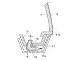
図8、図9は本発明の他の実施形態を示すもので、この実施形態では前記実施形態における化粧カバー12を用いず、背もたれ6の下端フレーム10の上部位置まで布カバー9が現れる形態とする場合である。 FIGS. 8 and 9 show another embodiment of the present invention. In this embodiment, the
すなわち図9に部分拡大断面図を示すように、布カバー9の下端部が糸15aによって縫着されて筒状部15が形成され、側面視鋭角に屈曲形成された略L字状をなす樹脂製の鉤状片14が筒状部15に挿入される。この鉤状片14の立ち上がり片14aが、前記芯材7と実質的に一体で芯材7の下端背面よりやや引込んだ位置に設けられているアルミ製の下フレーム10に形成されている孔16に下から引掛けるように挿入することにより布カバー9の下端が固定されるようになっている。 That is, as shown in a partially enlarged cross-sectional view in FIG. 9, a substantially L-shaped resin in which the lower end portion of the
そしてこの鉤状片14による係着部分を覆うように断面逆台形状に折曲形成された樹脂製の下カバー17が下フレーム10の下面側から嵌め込まれてネジ止めされ、この下カバー17のエッジ部17aで布カバー9が押圧されて緊張が与えられるとともにしわ切りされるようになっている。 Then, a resin
この実施形態によれば、鉤状片14を下フレーム10の孔16に差し込むだけで布カバー9の取り付けができ、また取り外し時には下カバー17を外したのち鉤状片14を下フレーム10の孔16から抜くだけでよく、さらに布カバー9の廃棄時には鉤状片14を筒状部15から抜くだけで筒状部15を布カバー9から分離させることができるので分別処理にも多くの手数を要することなく行うことができる。また鉤状片14による係着部分は下カバー17で覆われるので、外部には全く現れることがなく、椅子としてのデザインを損なうことがない。 According to this embodiment, the
図10は前記鉤状片14に代えピン18を用いて布カバー9を取り付けるようにした実施形態を示すもので、前記図9に相当する図として示している。 FIG. 10 shows an embodiment in which the
すなわち布カバー9を下フレーム10の孔19にピン18により圧入することで布カバー9を下フレーム10に固定するようにしたものである。他は図9と同様であるからこれと同一部材には同一符号を付すに留める。 That is, the
したがってこの実施形態によれば、布カバー9を下方に引張ってピン18を布カバー9の布地と共に下フレーム10の孔19に圧入するだけで布カバー9を緊張状態に張ることができ、布カバー9の取り外し時には布カバー9ごと下フレーム10に対し下方へ引張ればピン18ごと外れ、そのピン18を布カバー9から引き抜けば分別廃棄ができる。 Therefore, according to this embodiment, the
4 背フレーム
5 座部
6 背もたれ
7 芯材
8 クッション材
9 布カバー
10 下フレーム
11 鉤状突起
12 化粧カバー
13,16,19 孔
14 鉤状片
15 筒状部
15a 糸
17 下カバー
18 ピン4 Back
Claims (4)
Translated fromJapanese前記布カバーは、前記クッション材が前記芯材の両側端縁の外側に突出するように前記芯材の背当て面側から背面側へ回り込み、前記クッション材を含む芯材に被せられることが可能に、袋状に形成されており、
前記芯材の下半部の外面の複数箇所に切り起こし形状に形成された鉤状突起を設け、前記鉤状突起は、前記芯材の端部に起立して形成されたエッジとの間に溝部を形成するように位置しており、袋状に形成された布カバーを芯材に被せて布カバーの下半部の布地を前記鉤状突起に引っ掛けて固定し、この鉤状突起の存在部分を合成樹脂製化粧カバーで覆い、この化粧カバーの縁部にあるエッジ部を前記芯材の前記溝部に嵌め込み布カバーのしわ切りと鉤状突起の隠蔽とをなさしめるようにした
ことを特徴とする椅子の布張り構造。Attach a backrest-shaped core material to the raised part of the back frame supported by the pedestal supported by the pedestal so that it can tilt backwards, and attach a cushioning material such as urethane foam to the back surface of the core material. In theupholstered structure of achair that covers the core material including this cushioning material and covers it with a backrest,
The cloth cover may be wrapped around the core material including the cushion material by wrapping around from the back surface side of the core material to the back side so that the cushion material protrudes to the outside of both side edges of the core material. Is formed in a bag shape,
Provided with a plurality of cut-and-raised protrusions formed at a plurality of locations on the outer surface of the lower half of the core material, and the hook-shaped protrusions between the edges formed upright at the end of the core material The groove cover is positioned so that a cloth cover formed in a bag shape is placed on the core, and the fabric of the lower half of the cloth cover is hooked and fixed on the hook-shaped protrusion, and the presence of the hook-shaped protrusion A portion is covered with a synthetic resin decorative cover, and an edge portion of the decorative cover is fitted into the groove portion of the core material so that the cloth cover is creased and the hook-shaped protrusion is concealed. The upholstered structure of the chair.
ことを特徴とする請求項1に記載の椅子の布張り構造。Claim 1, wherein said engaging hole in a position corresponding to the coronoid of the fabric cover is provided, characterized in that to attach the fabric cover to the core engages the engaging hole to coronoidThe upholstered structureof the chairdescribed in 1 .
前記布カバーは、前記クッション材が前記芯材の両側端縁の外側に突出するように前記芯材の背当て面側から背面側へ回り込み、前記クッション材を含む芯材に被せられることが可能に、袋状に形成されており、
前記布カバーの下端部に筒状部を形成しこの筒状部に側面視鋭角に屈曲形成されたL字状をなす鉤状片を挿入する一方、前記背フレームの下端部に前記鉤状片の前記L字状の一片部が係合する係合孔を形成し、
前記クッション材を含む芯材に布カバーを被せたのち前記鉤状片の前記一片部をテンションを加えて前記係合孔に係着し、前記芯材の下端に前記鉤状片の係着部を隠蔽する断面逆台形状に折曲形成された下カバーを、前記下カバーのエッジ部で前記布カバーを押圧しそのしわ切りをするように、取り付けた
ことを特徴とする椅子の布張り構造。Attach a backrest-shaped core material to the raised part of the back frame supported by the pedestal supported by the pedestal so that it can tilt backwards, and attach a cushioning material such as urethane foam to the back surface of the core material. In theupholstered structure of achair that covers the core material including this cushioning material and covers it with a backrest,
The cloth cover may be wrapped around the core material including the cushion material by wrapping around from the back surface side of the core material to the back side so that the cushion material protrudes to the outside of both side edges of the core material. Is formed in a bag shape,
A cylindrical portion is formed at the lower end portion of the cloth cover, and an L-shaped piece that is bent at an acute angle when viewed from the side is inserted into the cylindrical portion, while the hook-shaped piece is inserted at the lower end portion of the back frame. Forming an engagement hole with which the L-shaped one-piece portion engages,
After covering the core material including the cushion material with a cloth cover, the one piece portion of the hook-like piece is engaged with the engagement hole by applying tension, and the hook-like piece engaging portion is attached to the lower end of the core member. The upholstery structure of a chair, wherein a lower cover bent in an inverted trapezoidal cross-section shape is attached so as to press the cloth cover at the edge portion of the lower cover and crease it .
前記布カバーは、前記クッション材が前記芯材の両側端縁の外側に突出するように前記芯材の背当て面側から背面側へ回り込み、前記クッション材を含む芯材に被せられることが可能に、袋状に形成されており、
前記背フレームの下端部に複数個の係合孔を形成し、
前記クッション材を含む芯材に布カバーを被せたのち前記係合孔にピンにより布カバーの布地を、前記ピンが前記布カバーの布地を前記係合孔内部へ押し込むように、共に押し込んで固定し、前記芯材の下端に前記ピンによる係着部を隠蔽する断面逆台形状に折曲形成された下カバーを、前記下カバーのエッジ部で前記布カバーを押圧しそのしわ切りをするように、取り付けた
ことを特徴とする椅子の布張り構造。Attach a backrest-shaped core material to the raised part of the back frame supported by the pedestal supported by the pedestal so that it can tilt backwards, and attach a cushioning material such as urethane foam to the back surface of the core material. In theupholstered structure of achair that covers the core material including this cushioning material and covers it with a backrest,
The cloth cover may be wrapped around the core material including the cushion material by wrapping around from the back surface side of the core material to the back side so that the cushion material protrudes to the outside of both side edges of the core material. Is formed in a bag shape,
Forming a plurality of engagement holes at the lower end of the back frame;
After covering the core material including the cushion material with a cloth cover, the cloth cover cloth is pushed by the pin into the engagement hole and fixed so that the pin pushes the cloth cover cloth into the engagement hole. Then, the lower cover bent in an inverted trapezoidal cross-section shape concealing the engaging portion by the pin at the lower end of the core material is pressed against the cloth cover at the edge portion of the lower cover and crushed. The upholstered structure of the chair, characterized in that it is attached.
Priority Applications (4)
| Application Number | Priority Date | Filing Date | Title |
|---|---|---|---|
| JP2003412101AJP4642346B2 (en) | 2003-12-10 | 2003-12-10 | Chair upholstery structure |
| TW093134732ATW200526148A (en) | 2003-12-10 | 2004-11-12 | Hood cloth tension gear of chair |
| KR1020040095581AKR101058629B1 (en) | 2003-12-10 | 2004-11-22 | Cloth attachment structure of chair |
| CNB2004101002621ACN100512718C (en) | 2003-12-10 | 2004-12-10 | Hood cloth tension gear of chair |
Applications Claiming Priority (1)
| Application Number | Priority Date | Filing Date | Title |
|---|---|---|---|
| JP2003412101AJP4642346B2 (en) | 2003-12-10 | 2003-12-10 | Chair upholstery structure |
Publications (2)
| Publication Number | Publication Date |
|---|---|
| JP2005168746A JP2005168746A (en) | 2005-06-30 |
| JP4642346B2true JP4642346B2 (en) | 2011-03-02 |
Family
ID=34732648
Family Applications (1)
| Application Number | Title | Priority Date | Filing Date |
|---|---|---|---|
| JP2003412101AExpired - LifetimeJP4642346B2 (en) | 2003-12-10 | 2003-12-10 | Chair upholstery structure |
Country Status (4)
| Country | Link |
|---|---|
| JP (1) | JP4642346B2 (en) |
| KR (1) | KR101058629B1 (en) |
| CN (1) | CN100512718C (en) |
| TW (1) | TW200526148A (en) |
Families Citing this family (14)
| Publication number | Priority date | Publication date | Assignee | Title |
|---|---|---|---|---|
| JP5031288B2 (en)* | 2006-07-24 | 2012-09-19 | 株式会社岡村製作所 | Chair backrest device |
| JP4893285B2 (en)* | 2006-12-11 | 2012-03-07 | トヨタ紡織株式会社 | Seat cover covering structure |
| JP5068525B2 (en)* | 2006-12-28 | 2012-11-07 | 株式会社岡村製作所 | Mounting device for back plate in chair |
| EP2534978B1 (en)* | 2010-02-10 | 2016-07-20 | Okamura Corporation | Stretching structure of chair upholstery material |
| WO2011145193A1 (en)* | 2010-05-19 | 2011-11-24 | Ykk株式会社 | Sheet retainer |
| USD697729S1 (en) | 2012-09-20 | 2014-01-21 | Steelcase Inc. | Chair |
| US8973990B2 (en) | 2012-09-20 | 2015-03-10 | Steelcase Inc. | Chair assembly |
| USD697728S1 (en) | 2012-09-20 | 2014-01-21 | Steelcase Inc. | Chair |
| USD702981S1 (en) | 2012-09-20 | 2014-04-22 | Steelcase Inc. | Chair |
| US8998339B2 (en)* | 2012-09-20 | 2015-04-07 | Steelcase Inc. | Chair assembly with upholstery covering |
| JP6067336B2 (en)* | 2012-11-08 | 2017-01-25 | デルタ工業株式会社 | Sheet |
| KR101446985B1 (en)* | 2014-03-24 | 2014-10-07 | 부호체어원(주) | Chair seat having detachable seat cover |
| CN104257162B (en)* | 2014-09-24 | 2017-09-19 | 惠阳维信纺织工业有限公司 | A kind of quick assembly |
| JP7695515B2 (en)* | 2021-03-23 | 2025-06-19 | テイ・エス テック株式会社 | Vehicle seat and manufacturing method for vehicle seat |
Family Cites Families (9)
| Publication number | Priority date | Publication date | Assignee | Title |
|---|---|---|---|---|
| US3907363A (en)* | 1974-04-22 | 1975-09-23 | Steelcase Inc | Upholstery system |
| JPH0438795U (en)* | 1990-07-30 | 1992-04-02 | ||
| JP2594847Y2 (en)* | 1991-11-29 | 1999-05-10 | イー・アイ・デュポン・ドウ・ヌムール・アンド・カンパニー | Upholstery equipment such as chairs |
| JP3496730B2 (en)* | 1994-03-24 | 2004-02-16 | アラコ株式会社 | Sheet |
| JPH07265564A (en)* | 1994-03-29 | 1995-10-17 | Giroflex Entwicklungs Ag | Facing structure of chair |
| JPH08308676A (en)* | 1995-05-16 | 1996-11-26 | Araco Corp | Seat back for automobile |
| JP3448133B2 (en)* | 1995-08-04 | 2003-09-16 | タカノ株式会社 | Attachment structure of chair skin member |
| JP3874375B2 (en)* | 1996-01-17 | 2007-01-31 | タカノ株式会社 | Chair upholstery structure |
| DE19839166C1 (en)* | 1998-08-28 | 1999-12-30 | Roessle & Wanner Gmbh | Adjustable frame for lounge bed |
- 2003
- 2003-12-10JPJP2003412101Apatent/JP4642346B2/ennot_activeExpired - Lifetime
- 2004
- 2004-11-12TWTW093134732Apatent/TW200526148A/ennot_activeIP Right Cessation
- 2004-11-22KRKR1020040095581Apatent/KR101058629B1/ennot_activeExpired - Fee Related
- 2004-12-10CNCNB2004101002621Apatent/CN100512718C/ennot_activeExpired - Fee Related
Also Published As
| Publication number | Publication date |
|---|---|
| CN100512718C (en) | 2009-07-15 |
| KR20050056860A (en) | 2005-06-16 |
| CN1626003A (en) | 2005-06-15 |
| TWI369192B (en) | 2012-08-01 |
| TW200526148A (en) | 2005-08-16 |
| KR101058629B1 (en) | 2011-08-22 |
| JP2005168746A (en) | 2005-06-30 |
Similar Documents
| Publication | Publication Date | Title |
|---|---|---|
| JP4642346B2 (en) | Chair upholstery structure | |
| JP4652767B2 (en) | Tensioning structure for upholstery for chair backrest, etc. | |
| US6220661B1 (en) | Chair back and method of assembly | |
| US5775778A (en) | Shape adaptable and renewable furniture system | |
| US7938433B2 (en) | Stroller soft goods attachment | |
| US7278691B2 (en) | Article of furniture having a recessed surface for a cushion | |
| US5540480A (en) | Versatile seat skirt | |
| US6409264B1 (en) | Interchangeable furniture cover system | |
| KR20180116730A (en) | Multi-purpose structure changeable chair | |
| JP4384004B2 (en) | Tensioning structure for upholstery in chair seats, etc. | |
| US20040145224A1 (en) | Seat core of child-care instrument | |
| JP5671333B2 (en) | Chair | |
| US9408470B2 (en) | Method of improving seat comfort, seat and cushion set according to the same | |
| US2550479A (en) | Chair back construction | |
| US6116693A (en) | Removable seat cushion system | |
| JP5964138B2 (en) | Chair | |
| JP2011045573A (en) | Chair | |
| JP4063043B2 (en) | Chair | |
| WO2025040913A1 (en) | Upholstered seat | |
| JP4446432B2 (en) | Chair structure and assembly method thereof | |
| JP5424199B2 (en) | Chair | |
| JP4484659B2 (en) | Tensioning structure for upholstery in chair seats, etc. | |
| JP7032080B2 (en) | Manufacturing method of skin material for body support of chair | |
| CN115107610B (en) | Head restraint assembly with pillow and method of manufacture | |
| JP6909336B2 (en) | Chair back |
Legal Events
| Date | Code | Title | Description |
|---|---|---|---|
| A621 | Written request for application examination | Free format text:JAPANESE INTERMEDIATE CODE: A621 Effective date:20061128 | |
| A131 | Notification of reasons for refusal | Free format text:JAPANESE INTERMEDIATE CODE: A131 Effective date:20100115 | |
| A521 | Request for written amendment filed | Free format text:JAPANESE INTERMEDIATE CODE: A523 Effective date:20100310 | |
| A131 | Notification of reasons for refusal | Free format text:JAPANESE INTERMEDIATE CODE: A131 Effective date:20100917 | |
| A521 | Request for written amendment filed | Free format text:JAPANESE INTERMEDIATE CODE: A523 Effective date:20101013 | |
| TRDD | Decision of grant or rejection written | ||
| A01 | Written decision to grant a patent or to grant a registration (utility model) | Free format text:JAPANESE INTERMEDIATE CODE: A01 Effective date:20101105 | |
| A01 | Written decision to grant a patent or to grant a registration (utility model) | Free format text:JAPANESE INTERMEDIATE CODE: A01 | |
| A61 | First payment of annual fees (during grant procedure) | Free format text:JAPANESE INTERMEDIATE CODE: A61 Effective date:20101201 | |
| R150 | Certificate of patent or registration of utility model | Free format text:JAPANESE INTERMEDIATE CODE: R150 Ref document number:4642346 Country of ref document:JP Free format text:JAPANESE INTERMEDIATE CODE: R150 | |
| FPAY | Renewal fee payment (event date is renewal date of database) | Free format text:PAYMENT UNTIL: 20131210 Year of fee payment:3 | |
| R250 | Receipt of annual fees | Free format text:JAPANESE INTERMEDIATE CODE: R250 | |
| R250 | Receipt of annual fees | Free format text:JAPANESE INTERMEDIATE CODE: R250 | |
| R250 | Receipt of annual fees | Free format text:JAPANESE INTERMEDIATE CODE: R250 | |
| R250 | Receipt of annual fees | Free format text:JAPANESE INTERMEDIATE CODE: R250 | |
| R250 | Receipt of annual fees | Free format text:JAPANESE INTERMEDIATE CODE: R250 | |
| R250 | Receipt of annual fees | Free format text:JAPANESE INTERMEDIATE CODE: R250 | |
| R250 | Receipt of annual fees | Free format text:JAPANESE INTERMEDIATE CODE: R250 | |
| R250 | Receipt of annual fees | Free format text:JAPANESE INTERMEDIATE CODE: R250 | |
| R250 | Receipt of annual fees | Free format text:JAPANESE INTERMEDIATE CODE: R250 | |
| R250 | Receipt of annual fees | Free format text:JAPANESE INTERMEDIATE CODE: R250 | |
| EXPY | Cancellation because of completion of term |