JP4641794B2 - Packet filter synchronization method and packet relay system - Google Patents
Packet filter synchronization method and packet relay systemDownload PDFInfo
- Publication number
- JP4641794B2 JP4641794B2JP2004380620AJP2004380620AJP4641794B2JP 4641794 B2JP4641794 B2JP 4641794B2JP 2004380620 AJP2004380620 AJP 2004380620AJP 2004380620 AJP2004380620 AJP 2004380620AJP 4641794 B2JP4641794 B2JP 4641794B2
- Authority
- JP
- Japan
- Prior art keywords
- filter
- packet
- control device
- input
- setting
- Prior art date
- Legal status (The legal status is an assumption and is not a legal conclusion. Google has not performed a legal analysis and makes no representation as to the accuracy of the status listed.)
- Expired - Fee Related
Links
Images


Landscapes
- Data Exchanges In Wide-Area Networks (AREA)
Description
Translated fromJapanese本発明は、パケットフィルタ同期方法及びパケット中継システムに関し、特に、パケット中継システムを制御装置と中継装置で構成したときに各装置のパケットフィルタの同期をとるパケットフィルタ同期方法及びパケット中継システムに関する。 The present invention relates to a packet filter synchronization method and a packet relay system, and more particularly to a packet filter synchronization method and a packet relay system that synchronize packet filters of respective devices when the packet relay system is configured by a control device and a relay device.
一般にパケット中継を取り扱う中継装置等のネットワーク機器は、制御部としてプロセッサを有するが、より高度な制御、あるいは新たなネットワーク・アプリケーションを導入しようとすると、プロセッサやメモリ等のリソース不足がこうした機能を導入する際の壁となる。 In general, network devices such as relay devices that handle packet relays have a processor as a control unit. However, when more advanced control or new network applications are introduced, such functions are introduced due to lack of resources such as processors and memory. It becomes a wall when doing.
そこで、そのようなネットワーク機器上で動かすアプリケーションを、外部から見た形態としてはネットワーク機器本体上で動作するように振舞うが、実際にはネットワーク機器本体とは別に用意したサーバ等の機器上で実行するようなことができれば、適宜必要な処理性能を追加することが可能になる。ここで、導入するアプリケーションの例としては、経路計算を行うルーティングデーモン、ファイル転送サービスを行うFTPサーバ、ハイパーテキストによる情報提供を行うHTTPサーバ等がある。 Therefore, an application that runs on such a network device behaves as if it operates on the network device itself as viewed from the outside, but actually runs on a device such as a server prepared separately from the network device itself. If it can be done, it becomes possible to add necessary processing performance as appropriate. Here, examples of applications to be introduced include a routing daemon that performs route calculation, an FTP server that performs a file transfer service, and an HTTP server that provides information in hypertext.
このようなネットワークにおける種々サービスを提供するアプリケーションをサービス別に実行機器を分けるという解決手法もあるが、ルーティングデーモンのように、その機器上で動かすことで本来の動作を行うようなアプリケーションでは、手を加えずにそのまま別機器上で実行させるのは困難である。また、一般にIPネットワークにおいては、同じホストアドレスで種々のサービスを提供する方が利用者から見た場合に憶えやすく、サービス提供形態として運用が容易である。 There is also a solution to divide applications that provide various services in such networks by service, but in applications such as the routing daemon that perform the original operation by moving on that device, hands are required. It is difficult to execute it as it is on another device without adding it. In general, in an IP network, providing various services with the same host address is easier to remember when viewed from the user, and is easy to operate as a service providing form.
このように、ネットワーク機器上で動かすアプリケーションを、外部から見た形態としては中継装置等のネットワーク機器上で動作するように振舞う一方、実際の実行を中継装置本体とは別に用意したサーバ等の外部機器上で実行することを実現する方法として、下記の方法が考えられる。 As described above, the application running on the network device behaves so as to operate on the network device such as the relay device as viewed from the outside, while the external execution such as the server prepared for the actual execution separately from the relay device main body. The following methods are conceivable as methods for realizing execution on the device.
この方法は、中継装置とは別に用意したサーバ等の制御装置に、中継装置本体の実インタフェースに対応する仮想インタフェースを配し、実行を委譲したいアプリケーションをその制御装置で仮想インタフェースに対し送受信を行うように実行させることで、あたかもその中継装置本体上でそのアプリケーションが動作しているかのように振舞わせることが可能となる。 In this method, a virtual interface corresponding to the real interface of the relay device main body is arranged in a control device such as a server prepared separately from the relay device, and an application whose execution is to be delegated is transmitted to and received from the virtual interface by the control device. By executing as described above, it is possible to behave as if the application is operating on the relay apparatus main body.
さらに、複数のアプリケーションを実行させたい場合、各々のアプリケーションに異なるコネクション識別子を割り当てて通信する特性を利用し、アプリケーション毎に処理の実行を担う制御装置を分けることが可能となる。 Furthermore, when it is desired to execute a plurality of applications, it is possible to divide a control device that performs processing for each application by using a characteristic of assigning different connection identifiers to the respective applications for communication.
この結果、論理的には単一の装置のように利用者から見える一方、提供するアプリケーション別に処理を担う制御装置を分けることにより、処理性能におけるスケーラビリティが確保できる。また、アプリケーションにおいて通信処理の実行開始または終了に応じ動的にコネクションを確立または削除することが可能で、運用も容易である。 As a result, while it is logically visible to the user like a single device, scalability in processing performance can be ensured by dividing the control device responsible for processing for each application to be provided. In addition, it is possible to dynamically establish or delete a connection in response to the start or end of execution of communication processing in an application, and operation is easy.
このような中継装置と制御装置からなるパケット中継システムに、ファイアウォール機能の実現等を目的にパケットフィルタを設定しようとする場合、そのままではそのパケットフィルタ設定を施した装置のみに反映されるため、パケットフィルタ設定を制御装置と中継装置それぞれに対し内容に応じて行わなければならない。 When a packet filter is set for the purpose of realizing a firewall function or the like in a packet relay system composed of such a relay device and a control device, the packet is reflected as it is only on the device that has performed the packet filter setting. Filter setting must be performed for each of the control device and the relay device according to the contents.
また、このようなパケット中継システムではパケット中継処理は中継装置が担うため、通常パケットフィルタ設定は実体として中継装置にて行う必要があるが、ルーティング処理等の制御処理を制御装置で実行することを考えると、それらに関するパケットフィルタ設定は制御装置に対し行うことになる。 In such a packet relay system, since the packet relay processing is performed by the relay device, the normal packet filter setting needs to be performed by the relay device as an entity, but control processing such as routing processing is executed by the control device. Considering this, the packet filter setting related to them is performed for the control device.
さらに、実装によってはパケットフィルタが中継処理性能を低下させる要因となったり、設定可能なパケットフィルタの数に制限がある場合もあるため、パケット中継処理の性能を考慮してパケット中継システムを構成する各パケット中継処理にパケットフィルタ設定を行うことが好ましい場合もある。しかし、機器の運用のしやすさを考えると、中継装置と制御装置にばらばらにパケットフィルタ設定を行うのは煩雑であり、管理・運用上手間がかかるという問題があった。 In addition, depending on the implementation, the packet filter may cause a decrease in the relay processing performance, or the number of packet filters that can be set is limited, so the packet relay system is configured in consideration of the performance of the packet relay processing. It may be preferable to set a packet filter for each packet relay process. However, considering the ease of operation of the device, it is troublesome to set the packet filter in the relay device and the control device separately, and it takes time and effort for management and operation.
本発明は、上記の点に鑑みなされたものであり、制御装置に設定したパケットフィルタの設定を中継装置及び他の制御装置のパケットフィルタに設定し、制御装置でのパケットフィルタ設定でパケット中継システム全体に必要なパケットフィルタ設定を自動的に行うことができるパケットフィルタ同期方法及びパケット中継システムを提供することを目的とする。 The present invention has been made in view of the above points, and sets the packet filter set in the control device in the packet filter of the relay device and other control devices, and sets the packet filter in the control device to the packet relay system. It is an object of the present invention to provide a packet filter synchronization method and a packet relay system that can automatically perform packet filter settings necessary for the whole.
請求項1に記載の発明は、中継装置と制御装置で構成され、前記制御装置で前記中継装置のインタフェースに対応する仮想インタフェースを形成し、前記仮想インタフェースに対する操作を中継装置の対応する実インタフェース上の動作とすることで中継装置と制御装置が一体化して動作するパケット中継システムのパケットフィルタ同期方法であって、
前記制御装置で入力されたパケットフィルタに設定されるフィルタ情報を前記制御装置のテーブルに設定し、
前記フィルタ情報を前記中継装置のパケットフィルタに反映する場合に前記フィルタ情報を前記中継装置に通知し、
前記制御装置から通知されたフィルタ情報を前記中継装置のテーブルに設定し、
前記中継装置は、入力フィルタの前段で前記制御装置に処理が移るパケットを振り分け、
前記制御装置で入力されたパケットフィルタに設定されるフィルタ情報の前記制御装置のテーブルへの設定は、前記制御装置で入力されたパケットフィルタのフィルタ情報のうち転送フィルタに設定されるフィルタ情報を前記制御装置のテーブルに設定せず、前記制御装置で入力されたパケットフィルタのフィルタ情報のうち入力フィルタと出力フィルタに設定されるフィルタ情報を前記制御装置のテーブルに設定し、
前記制御装置から通知されたフィルタ情報の前記中継装置のテーブルへの設定は、前記制御装置で入力された入力フィルタと出力フィルタと転送フィルタに設定されるフィルタ情報を前記中継装置のテーブルに設定することにより、
制御装置に設定したパケットフィルタの設定を中継装置のパケットフィルタに設定し、制御装置でのパケットフィルタ設定でパケット中継システム全体に必要なパケットフィルタ設定を自動的に行うことができる。The invention according to
Set the filter information set in the packet filter input by the control device in the table of the control device,
Notifying the relay device of the filter information when the filter information is reflected in the packet filter of the relay device;
Set the filter information notified from the control device in the table of the relay device,
The relay device distributes a packet to be processed by the control device before the input filter,
The setting of the filter information set in the packet filter input by the control device to the table of the control device is the filter information set in the transfer filter among the filter information of the packet filter input by the control device. Without setting in the table of the control device, set the filter information set in the input filter and the output filter among the filter information of the packet filter input in the control device in the table of the control device,
The filter information notified from the control device is set in the table of the relay device by setting the filter information set in the input filter, the output filter, and the transfer filter input in the control device in the table of the relay device. By
The packet filter setting set in the control device can be set in the packet filter of the relay device, and the packet filter setting necessary for the entire packet relay system can be automatically performed by the packet filter setting in the control device.
請求項4に記載の発明は、中継装置と制御装置で構成され、前記制御装置で前記中継装置のインタフェースに対応する仮想インタフェースを形成し、前記仮想インタフェースに対する操作を中継装置の対応する実インタフェース上の動作とすることで中継装置と制御装置が一体化して動作するパケット中継システムであって、
前記制御装置で入力されたパケットフィルタに設定されるフィルタ情報を前記制御装置のテーブルに設定するパケットフィルタ設定手段と、
前記フィルタ情報を前記中継装置のパケットフィルタに反映する場合に前記フィルタ情報を前記中継装置に通知するパケットフィルタ設定通知手段と、
前記制御装置から通知されたフィルタ情報を前記中継装置のテーブルに設定する通知パケットフィルタ設定手段を有し、
前記中継装置は、前記制御装置に処理が移るパケットを振り分ける手段が入力フィルタの前段に配置されており、
前記パケットフィルタ設定手段は、前記制御装置で入力されたパケットフィルタのフィルタ情報のうち転送フィルタに設定されるフィルタ情報を前記制御装置のテーブルに設定せず、前記制御装置で入力されたパケットフィルタのフィルタ情報のうち入力フィルタと出力フィルタに設定されるフィルタ情報を前記制御装置のテーブルに設定し、
前記通知パケットフィルタ設定手段は、前記制御装置で入力された入力フィルタと出力フィルタと転送フィルタに設定されるフィルタ情報を前記中継装置のテーブルに設定することにより、
制御装置に設定したパケットフィルタの設定を中継装置のパケットフィルタに設定し、制御装置でのパケットフィルタ設定でパケット中継システム全体に必要なパケットフィルタ設定を自動的に行うことができる。The invention according to claim4 includes a relay device and a control device, the control device forms a virtual interface corresponding to the interface of the relay device, and an operation on the virtual interface is performed on a real interface corresponding to the relay device. A packet relay system in which the relay device and the control device operate in an integrated manner,
Packet filter setting means for setting filter information set in the packet filter input by the control device in the table of the control device;
A packet filter setting notification means for notifying the relay device of the filter information when the filter information is reflected in the packet filter of the relay device;
Have a notification packet filter setting means for setting the filter information notified from the control device to the table of the relaydevice,
In the relay device, means for distributing packets to be transferred to the control device is arranged in the front stage of the input filter,
The packet filter setting means does not set the filter information set in the transfer filter out of the filter information of the packet filter input by the control device in the table of the control device, and does not set the packet filter input by the control device. Of the filter information, set the filter information set in the input filter and the output filter in the table of the control device,
The notification packet filter setting means sets the filter information set in the input filter, the output filter, and the transfer filter input by the control device in the table of the relay device ,
The packet filter setting set in the control device can be set in the packet filter of the relay device, and the packet filter setting necessary for the entire packet relay system can be automatically performed by the packet filter setting in the control device.
本発明によれば、制御装置に設定したパケットフィルタの設定を中継装置及び他の制御装置のパケットフィルタに設定し、制御装置でのパケットフィルタ設定でパケット中継システム全体に必要なパケットフィルタ設定を自動的に行うことができる。 According to the present invention, the packet filter setting set in the control device is set in the packet filter of the relay device and other control devices, and the packet filter setting required in the entire packet relay system is automatically set by the packet filter setting in the control device. Can be done automatically.
以下、図面に基づいて本発明の実施形態について説明する。
<パケット中継システムの構造>
まず、本発明に適用されるパケット中継システムについて図1を用いて説明する。Hereinafter, embodiments of the present invention will be described with reference to the drawings.
<Structure of packet relay system>
First, a packet relay system applied to the present invention will be described with reference to FIG.
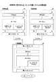
図1において、中継装置20は、複数のインタフェースを持ち、そのうちの1つのインタフェースで制御装置10と接続される。通常、制御装置10で動作しているプロセス(アプリケーション)15から見えるインタフェースは、制御装置10が持つ実インタフェース11である。 In FIG. 1, the
中継装置20に複数の制御装置10,30が接続されていると、パケット中継システムの外部からは中継装置20に接続された数の制御装置が見えることになり、アクセスする制御装置が異なると、異なるIPアドレス宛にアクセスすることになる。この場合、外部から中継装置20のIPアドレス宛にアクセスして、複数の制御装置10,30にアクセス可能とするために、各制御装置10,30に仮想インタフェース12,32を配備する。 When a plurality of
仮想インタフェース12,32は、デバイスドライバの一種であるが、カーネル13,33から受信した送信パケットを実インタフェース11,31から送信するのではなく、仮想インタフェース12,32に書き込んで、いったんトンネリングプロセス14,34にこのパケットを読み出し、トンネリングプロセス14,34が実インタフェース11,31に対して送信を行うものである。 The
このトンネリングプロセス14,34では、どの仮想インタフェース12,32から受信したかが分かるために、その仮想インタフェース12,32の番号を受信したパケットのヘッダに付与する。このヘッダを付与したパケットを中継装置20に対して送信し、中継装置20はヘッダに付与された仮想インタフェース12,32の番号から、どの実インタフェースから送信すればよいかが分かるため、当該実インタフェースに送信パケットを出力する。この制御装置10にあるトンネリングプロセス14,34と、中継装置20の間の通信パスをトンネルと呼ぶ。 In this
また逆に、外部のネットワークから中継装置20がパケットを受信すると、中継装置20は、受信パケットの宛先ポート番号を識別し、どの制御装置10,30に送信するべきかを判断できる。この宛先ポート番号によって、どのトンネルに受信パケットを振り分けるかを決定し、受信パケットはトンネルを通じて該当する制御装置10,30に送信される。 Conversely, when the
制御装置10,30に到着したパケットは、いったんトンネルを終端する前記トンネリングプロセス14,34が受信する。トンネリングプロセス14,34は、受信した実インタフェースに対応する仮想インタフェース12,32に受信したパケットを書き込み、通信の終端であるプロセス(アプリケーション)15,35は、この仮想インタフェース12,32からパケットを受信する。 The packets arriving at the
以上の一連の流れによって、制御装置10,30それぞれで動作しているプロセス(アプリケーション)は、仮想インタフェースにアクセスすることによって、あたかも中継装置20の実インタフェースをアクセスしているような動作を実現し、中継装置と制御装置が一体化して動作する。複数の制御装置10を中継装置20に接続し、これら複数の制御装置10ではルーティングプロセスやwebサーバ、FTPサーバなどのプロセス(アプリケーション)を動作させることで、外部からは1つの装置(中継装置20)が複数のサービスを行っているように見せる。
<制御装置のパケットフィルタ構成>
上記構成のパケット中継システムで、1つの制御装置にて、ファイアウォールを動作するべくパケットフィルタの設定を行う場合、そのパケットフィルタは制御装置のみに反映される。このパケットフィルタとは、例えばLinuxにおいてはiptablesである。iptablesでは、自装置に入力するパケットに対するフィルタであるINPUTフィルタ(入力フィルタ)、自装置宛ではなく他の装置へ転送(フォワーディング)するパケットに対するフィルタであるFORWARDフィルタ(転送フィルタ)、自装置が出力するパケットに対するフィルタであるOUTPUTフィルタ(出力フィルタ)がある。Through the above-described series of processes, the processes (applications) operating in the
<Packet filter configuration of control device>
In the packet relay system configured as described above, when a packet filter is set to operate a firewall in one control device, the packet filter is reflected only in the control device. This packet filter is iptables in Linux, for example. In iptables, an INPUT filter (input filter) that is a filter for a packet that is input to the own device, a FORWARD filter (transfer filter) that is a filter for a packet that is forwarded to another device instead of being addressed to the own device, and the own device outputs There is an OUTPUT filter (output filter) that is a filter for a packet to be transmitted.
図2は、1つの制御装置におけるパケットフィルタの構成図を示す。同図中、実インタフェース40は、下位レイヤ処理41を介してIPレイヤ処理42を接続されている。IPレイヤ処理42内にはユーザ空間にプロセス(アプリケーション)43が置かれ、カーネルに入力パケットのルーティングを行うルーティング部44と、自装置に入力するパケットに対する入力フィルタ45と、他の装置へ転送するパケットに対する転送フィルタ46と、出力するパケットに対する出力フィルタ47が形成されている。上記入力フィルタ45,転送フィルタ46,出力フィルタ47それぞれに設定するフィルタ情報は図示しないフィルタテーブルに登録される。 FIG. 2 shows a configuration diagram of a packet filter in one control apparatus. In the figure, an
図3は、制御装置におけるパケットフィルタ処理のフローチャートを示す。同図中、ステップS10でパケットが入力され、ステップS11でルーティング部44にてパケットの宛先が当該制御装置であるか否かを判別する。パケットの宛先が当該制御装置ではない場合にはステップS12で転送フィルタ46にて廃棄対象パケットであるか否かを判別し、廃棄対象パケットではない場合はステップS13でこのパケットを宛先である他の装置に出力する。廃棄対象パケットである場合はステップS14でこのパケットを廃棄する。 FIG. 3 shows a flowchart of packet filter processing in the control device. In the figure, a packet is input in step S10, and in step S11, the
一方、パケットの宛先が当該制御装置である場合にはステップS15で入力フィルタ45にて廃棄対象パケットであるか否かを判別し、廃棄対象パケットではない場合はステップS16でこのパケットをプロセス43にて処理する。廃棄対象パケットである場合はステップS14でこのパケットを廃棄する。 On the other hand, if the destination of the packet is the control device, it is determined in step S15 whether or not it is a packet to be discarded by the
プロセス43にて処理されたパケットはステップS17で出力フィルタ47にて廃棄対象パケットであるか否かを判別し、廃棄対象パケットではない場合はステップS18でこのパケットを外部(ネットワーク)に出力する。廃棄対象パケットである場合はステップS14でこのパケットを廃棄する。
<第1実施形態>
<パケット中継システムのパケットフィルタ>
図4は、本発明のパケット中継システムの第1及び第2実施形態におけるパケットフィルタの構成図を示す。なお、この図では仮想インタフェース、トンネリングプロセス等は図示していない。同図中、中継装置20に制御装置10が接続されている。制御装置10には、ユーザ空間にプロセス(アプリケーション)43が置かれ、カーネルに入力パケットのルーティングを行うルーティング部44と、自装置に入力するパケットに対する入力フィルタ45と、他の装置へ転送するパケットに対する転送フィルタ46と、出力するパケットに対する出力フィルタ47が形成されている。The packet processed in the
<First Embodiment>
<Packet filter for packet relay system>
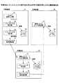
FIG. 4 shows a block diagram of a packet filter in the first and second embodiments of the packet relay system of the present invention. In this figure, a virtual interface, a tunneling process, etc. are not shown. In the figure, the
また、中継装置20にはユーザ空間にプロセス(アプリケーション)53が置かれ、カーネルに入力パケットのルーティングを行うルーティング部54と、パケットのTCP(transmission control protocol)宛先ポート番号によって入力パケットを中継装置20と制御装置10に振り分ける振り分け部51と、自装置に入力するパケットに対する入力フィルタ55と、他の装置へ転送するパケットに対する転送フィルタ56と、出力するパケットに対する出力フィルタ57が形成されている。この中継装置20はネットワークA,Bに接続されている。 The
中継装置20の振り分け部51から制御装置10に振り分けられたパケットはトンネルを通じて制御装置10に送信され、制御装置10内でトンネルを終端するトンネリングプロセスで受信されて仮想インタフェースに書き込まれ、仮想インタフェースからルーティング部44に供給される。また、制御装置10の出力フィルタ47の出力するパケットは仮想インタフェースに書き込まれ、トンネリングプロセスがこのパケットを読み出し、トンネルを通じて中継装置20に対して送信する。 A packet distributed from the
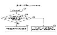
図5は、中継装置20の振り分け部51における振り分け処理のフローチャートを示す。同図中、ステップS20でパケットが振り分け部51に入力され、ステップS21でパケットのTCP宛先ポートが制御装置10で動作しているプロセス23宛であるか否かを判別する。パケットの宛先が制御装置10のプロセス23ではない場合にはステップS22で中継装置20(自装置)のプロセス53にパケットを渡し処理を行う。パケットの宛先が制御装置10のプロセス23である場合にはステップS23でトンネルを通じて制御装置10のプロセス23にパケットを渡し処理を行う。 FIG. 5 shows a flowchart of the distribution process in the
ここで、制御装置10で動作しているプロセスのポート番号宛のパケットは制御装置10に移され、それ以外のポート番号宛パケットは中継装置20で動作しているプロセスのポート番号に向かう。このため、例えばネットワークAからの受信パケットを遮断する場合、制御装置10と中継装置20の入力フィルタ45,55に、ネットワークAからの受信パケットは遮断するという同一設定を行う必要がある。
<パケットフィルタ同期>
図6は、本発明のパケットフィルタ同期方法の第1乃至第4実施形態における機能構成図を示す。同図中、制御装置10のフィルタテーブル61には、制御装置10の入力フィルタ45,転送フィルタ46,出力フィルタ47それぞれに設定するフィルタ情報が登録され、同様に、中継装置20のフィルタテーブル71には、中継装置20の入力フィルタ55,転送フィルタ56,出力フィルタ57それぞれに設定するフィルタ情報が登録される。Here, the packet addressed to the port number of the process operating in the
<Packet filter synchronization>
FIG. 6 is a functional configuration diagram in the first to fourth embodiments of the packet filter synchronization method of the present invention. In the figure, filter information to be set for each of the
制御装置10に設けられたフィルタ設定入力部62で制御装置10の入力フィルタ45,転送フィルタ46,出力フィルタ47の少なくともいずれかに設定するフィルタ情報が入力され、上記フィルタ情報は新規設定や変更指示のメッセージ(またはコマンド)としてパケットフィルタ設定部63に供給される。パケットフィルタ設定部63は、上記メッセージから制御装置10の入力フィルタ45,転送フィルタ46,出力フィルタ47のどの部分に対する設定であるかを検出してフィルタテーブル61に登録すると共に、上記メッセージをパケットフィルタ判定部64に通知する。 Filter information to be set in at least one of the
パケットフィルタ判定部64は、上記メッセージからフィルタ設定が中継装置20の入力フィルタ55,転送フィルタ56,出力フィルタ57に反映されるべきか否かを判定し、反映されるべき場合には、上記フィルタ情報を中継装置20に通知するようパケットフィルタ設定通知部65に依頼する。この依頼により、パケットフィルタ設定通知部65は、中継装置20で動作している通知パケットフィルタ設定部73にフィルタ設定を依頼するメッセージを発行する。 The packet
中継装置20の通知パケットフィルタ設定部73は、上記フィルタ設定依頼メッセージの通知を受け、上記メッセージからフィルタ設定が中継装置20の入力フィルタ55,転送フィルタ56,出力フィルタ57のどの部分に対する設定であるかを検出してフィルタテーブル71に登録する。 The notification packet
これにより、制御装置10において設定したパケットフィルタ設定を、制御装置10と共にパケット中継システムを構成する中継装置20に反映し、一箇所でのパケットフィルタ設定でパケット中継システム全体に必要なパケットフィルタ設定を行うことができる。 As a result, the packet filter setting set in the
なお、上記パケットフィルタ設定部63,パケットフィルタ判定部64,パケットフィルタ設定通知部65は制御装置10においてフィルタテーブル同期用プロセスにて実現でき、通知パケットフィルタ設定部73は中継装置20においてフィルタテーブル同期用プロセスにて実現できる。 The packet
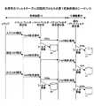
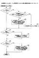
図4に示す構成、つまり、中継装置20から制御装置10に処理が移るパケットを振り分ける振り分け部51が入力フィルタ55の前段に配置された構成におけるフィルタテーブル同期用プロセスの第1実施形態のフローチャートを図7に示し、そのシーケンスを図8に示す。 FIG. 4 is a flowchart of the first embodiment of the filter table synchronization process in the configuration shown in FIG. 4, that is, the configuration in which the
図7において、ステップS30で入力フィルタの設定であるか否かを判別し、入力フィルタ設定の場合にはステップS31に進み、制御装置10の入力フィルタ45に設定内容を設定する(図8のステップS31a)と共に、同一内容を中継装置20の入力フィルタ55に設定(図8のステップS31b)する。 In FIG. 7, it is determined whether or not the input filter is set in step S30. If the input filter is set, the process proceeds to step S31, and the setting content is set in the
次に、ステップS32で転送フィルタの設定であるか否かを判別し、転送フィルタ設定の場合にはステップS33に進み、制御装置10の転送フィルタ46に設定は行わず、設定内容を中継装置20の転送フィルタ56に設定する。 Next, in step S32, it is determined whether or not the transfer filter is set. If the transfer filter is set, the process proceeds to step S33, the
次に、ステップS34で出力フィルタの設定であるか否かを判別し、出力フィルタ設定の場合にはステップS35に進み、制御装置10の出力フィルタ47に設定内容を設定する(図8のステップS35a)と共に、同一内容を中継装置20の出力フィルタ57に設定(図8のステップS35b)する。
<第2実施形態>
制御装置10で動作しているプロセス宛が指定されたパケットに対する入力フィルタ設定を行う場合は、制御装置10の入力フィルタ45のみに設定されれば良く、中継装置20の入力フィルタ55については同期させる必要はない。この場合のフィルタテーブル同期用プロセスの第2実施形態のフローチャートを図9に示し、そのシーケンスを図10に示す。Next, in step S34, it is determined whether or not the output filter is set. If the output filter is set, the process proceeds to step S35, and the setting content is set in the
<Second Embodiment>
When performing the input filter setting for the packet designated for the process operating in the
図9において、図7と異なる部分は、ステップS31の代りにステップS36で入力フィルタの設定が制御装置10で動作しているプロセスを限定した設定であるか否かを判別し、入力フィルタの設定が制御装置10で動作しているプロセスを限定した設定の場合はステップS38にて制御装置10の入力フィルタ45に設定内容を設定(図10のステップS37)し、中継装置20の入力フィルタ55に設定は行わず、入力フィルタの設定が制御装置10で動作しているプロセスを限定した設定ではない場合はステップS38にて制御装置10の入力フィルタ45に設定内容を設定(図10のステップS38a)し、同一内容を中継装置20の入力フィルタ55に設定(図10のステップS38b)する点である。
<第3実施形態>
図11は、本発明のパケット中継システムの第3及び第4実施形態におけるパケットフィルタの構成図を示す。この図で図4と異なる部分は、中継装置20から制御装置10に処理が移るパケットを振り分ける振り分け部51が入力フィルタ55の後段に配置されている点である。この図では仮想インタフェース、トンネリングプロセス等は図示していない。9 differs from FIG. 7 in that, instead of step S31, in step S36, it is determined whether or not the input filter setting is a setting that limits the processes operating in the
<Third Embodiment>
FIG. 11 shows a configuration diagram of a packet filter in the third and fourth embodiments of the packet relay system of the present invention. 4 is different from FIG. 4 in that a
図11において、中継装置20に制御装置10が接続されている。制御装置10には、ユーザ空間にプロセス(アプリケーション)43が置かれ、カーネルに入力パケットのルーティングを行うルーティング部44と、自装置に入力するパケットに対する入力フィルタ45と、他の装置へ転送するパケットに対する転送フィルタ46と、出力するパケットに対する出力フィルタ47が形成されている。 In FIG. 11, the
また、中継装置20にはユーザ空間にプロセス(アプリケーション)53が置かれ、カーネルに入力パケットのルーティングを行うルーティング部54と、パケットのTCP宛先ポート番号によって入力パケットを中継装置20と制御装置10に振り分ける振り分け部51と、自装置に入力するパケットに対する入力フィルタ55と、他の装置へ転送するパケットに対する転送フィルタ56と、出力するパケットに対する出力フィルタ57が形成されている。この中継装置20はネットワークA,Bに接続されている。 The
中継装置20の振り分け部51から制御装置10に振り分けられたパケットはトンネルを通じて制御装置10に送信され、制御装置10内でトンネルを終端するトンネリングプロセスで受信されて仮想インタフェースに書き込まれ、仮想インタフェースからルーティング部44に供給される。また、制御装置10の出力フィルタ47の出力するパケットは仮想インタフェースに書き込まれ、トンネリングプロセスがこのパケットを読み出し、トンネルを通じて中継装置20に対して送信する。 A packet distributed from the
この構成では、制御装置10に処理が移るパケットは中継装置20の入力フィルタ55を通ってから制御装置10に移動する。すなわち、制御装置10に移ってからは、入力フィルタ45を再度通る必要が無いため、入力フィルタ45の設定は行う必要がない。 In this configuration, a packet whose processing is transferred to the
ただし、制御装置10で動作しているプロセス宛と明に指定された入力フィルタを設定する場合、設定方法として2通りの方法がある。1つ目としては、中継装置20の入力フィルタ55に設定する方法(図12、図13)であり、もう1つとしては、制御装置10の入力フィルタ45に設定する方法(図14、図15)である。それぞれの方法には、それぞれに有利な点が考えられる。 However, when setting an input filter designated as addressed to a process operating in the
中継装置20の入力フィルタ55に設定する場合、フィルタにてパケットを廃棄するルールだと中継装置20でパケットの廃棄ができ、制御装置10に処理を移すことなく処理が完了する。 When setting in the
また、制御装置10にて入力フィルタ55を設定する場合、中継装置20におけるフィルタが少なくなるために、フィルタ検索処理が中継装置20と制御装置10とで分散されることになり、トータルとしてのパフォーマンスが上がる。 Further, when the
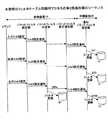
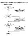
図11に示す構成、つまり、中継装置20から制御装置10に処理が移るパケットを振り分ける振り分け部51が入力フィルタ55の後段に配置された構成で中継装置20の入力フィルタ55に設定する方法のフィルタテーブル同期用プロセスの第3実施形態のフローチャートを図12に示し、そのシーケンスを図13に示す。 The filter shown in FIG. 11, that is, a method of setting the
図12において、ステップS40で入力フィルタの設定であるか否かを判別し、入力フィルタ設定の場合にはステップS41に進み、制御装置10の入力フィルタ45に設定は行わず、設定内容を中継装置20の入力フィルタ55に設定(図13のステップS41)する。 In FIG. 12, it is determined whether or not the input filter is set in step S40. If the input filter is set, the process proceeds to step S41, the setting is not performed in the
次に、ステップS42で転送フィルタの設定であるか否かを判別し、転送フィルタ設定の場合にはステップS43に進み、制御装置10の転送フィルタ46に設定は行わず、設定内容を中継装置20の転送フィルタ56に設定(図13のステップS43)する。 Next, in step S42, it is determined whether or not the transfer filter is set. If the transfer filter is set, the process proceeds to step S43, the
次に、ステップS44で出力フィルタの設定であるか否かを判別し、出力フィルタ設定の場合にはステップS45に進み、制御装置10の出力フィルタ47に設定内容を設定する(図13のステップS45a)と共に、同一内容を中継装置20の出力フィルタ57に設定(図13のステップS45b)する。
<第4実施形態>
図11に示す構成、つまり、中継装置20から制御装置10に処理が移るパケットを振り分ける振り分け部51が入力フィルタ55の後段に配置された構成で中継装置10の入力フィルタ55に設定する別の方法のフィルタテーブル同期用プロセスのフローチャートを図14に示し、そのシーケンスを図15に示す。Next, in step S44, it is determined whether or not the output filter is set. If the output filter is set, the process proceeds to step S45, and the setting content is set in the
<Fourth embodiment>
Another method of setting the
図14において、ステップS50で入力フィルタの設定であるか否かを判別し、入力フィルタ設定の場合には、ステップS51で上記入力フィルタの設定が制御装置10で動作しているプロセスを限定した設定であるか否かを判別する。 In FIG. 14, it is determined whether or not the input filter is set in step S50, and in the case of the input filter setting, in step S51, the setting in which the input filter setting is limited to the process operating in the
入力フィルタの設定が制御装置10で動作しているプロセスを限定した設定の場合はステップS52にて制御装置10の入力フィルタ45に設定内容を設定(図15のステップS52)し、中継装置20の入力フィルタ55に設定は行わない。 If the setting of the input filter is limited to the processes operating in the
入力フィルタの設定が制御装置10で動作しているプロセスを限定した設定ではない場合はステップS53にて制御装置10の入力フィルタ45に設定を行わず、設定内容を中継装置20の入力フィルタ55に設定(図15のステップS53)する。 If the setting of the input filter is not a setting that limits the processes operating in the
次に、ステップS54で転送フィルタの設定であるか否かを判別し、転送フィルタ設定の場合にはステップS55に進み、制御装置10の転送フィルタ46に設定は行わず、設定内容を中継装置20の入力フィルタ56に設定(図15のステップS55)する。 Next, in step S54, it is determined whether or not the transfer filter is set. If the transfer filter is set, the process proceeds to step S55, and the
次に、ステップS56で出力フィルタの設定であるか否かを判別し、出力フィルタ設定の場合にはステップS57に進み、制御装置10の出力フィルタ47に設定内容を設定する(図15のステップS57a)と共に、同一内容を中継装置20の出力フィルタ57に設定(図15のステップS57b)する。
<第5実施形態>
中継装置に接続された複数の制御装置では、それぞれ別のプロセスが動作しており、プロセスによって異なるフィルタルールを設定することがある。特にサーバとして動作するプロセスは、well knownポートと呼ばれるTCPのポート番号を使用して外部との通信を行う。Next, in step S56, it is determined whether or not the output filter is set. If the output filter is set, the process proceeds to step S57, and the setting content is set in the
<Fifth Embodiment>
In a plurality of control devices connected to the relay device, different processes are operating, and different filter rules may be set depending on the processes. In particular, a process operating as a server communicates with the outside using a TCP port number called a well-known port.
フィルタのルールに、ある特定のプロセスとの通信という条件をつける場合、そのルールに宛先のTCPポート番号を明に記述する。異なる制御装置では同一のTCPポート番号は用いないとして、フィルタのルールに宛先のTCPポートの条件を入れた場合は、その接続先はいずれかの制御装置に限定される。 When a condition for communication with a specific process is added to the filter rule, the destination TCP port number is clearly described in the rule. If the same TCP port number is not used in different control devices, and the destination TCP port condition is included in the filter rule, the connection destination is limited to one of the control devices.
従って、フィルタのルールに宛先のTCPポート番号を含んだフィルタテーブルが登録された場合、制御装置で動作しているフィルタテーブル同期用プロセスは、これを中継装置や他の制御装置に登録されたことを通知しない。 Therefore, when a filter table including the destination TCP port number is registered in the filter rule, the filter table synchronization process operating in the control device is registered in the relay device or other control device. Do not notify.
この場合の動作の例としては、例えば特定の制御装置にて動作しているルーティングプロセスは、ネットワークAからの入力は受け入れ、別の制御装置30にて動作しているウェブサーバのプロセスはネットワークAからの入力は受け入れないという動作をさせたい場合には、各制御装置の入力フィルタには別々のフィルタ情報を登録する。 As an example of the operation in this case, for example, a routing process operating in a specific control device accepts input from the network A, and a web server process operating in another
別々のフィルタ情報を登録した入力フィルタは、プロセス別すなわち宛先のTCPポート番号別であるため、中継装置に登録する必要はない。中継装置には、そのTCPポート番号宛のパケットは各制御装置に処理を移すための振り分け部があり、各制御装置にて宛先毎の入力フィルタを作る。
<パケット中継システムのパケットフィルタ>
図16は、本発明のパケット中継システムの第5実施形態におけるパケットフィルタの構成図を示す。なお、この図では仮想インタフェース、トンネリングプロセス等は図示していない。同図中、中継装置20に制御装置10,30が接続されている。制御装置10には、ユーザ空間にプロセス(アプリケーション)43が置かれ、カーネルに入力パケットのルーティングを行うルーティング部44と、自装置に入力するパケットに対する入力フィルタ45と、他の装置へ転送するパケットに対する転送フィルタ46と、出力するパケットに対する出力フィルタ47が形成されている。Since the input filters in which different filter information is registered are classified by process, that is, by destination TCP port number, it is not necessary to register them in the relay apparatus. The relay apparatus has a distribution unit for transferring the packet addressed to the TCP port number to each control apparatus, and each control apparatus creates an input filter for each destination.
<Packet filter for packet relay system>
FIG. 16 shows a block diagram of a packet filter in the fifth embodiment of the packet relay system of the present invention. In this figure, a virtual interface, a tunneling process, etc. are not shown. In the figure,
また、中継装置20にはユーザ空間にプロセス(アプリケーション)53が置かれ、カーネルに入力パケットのルーティングを行うルーティング部54と、パケットのTCP宛先ポート番号によって入力パケットを中継装置20と制御装置10,30に振り分ける振り分け部51と、自装置に入力するパケットに対する入力フィルタ55と、他の装置へ転送するパケットに対する転送フィルタ56と、出力するパケットに対する出力フィルタ57が形成されている。この中継装置20はネットワークA,Bに接続されている。 The
更に、制御装置30には、ユーザ空間にプロセス(アプリケーション)83が置かれ、カーネルに入力パケットのルーティングを行うルーティング部84と、自装置に入力するパケットに対する入力フィルタ85と、他の装置へ転送するパケットに対する転送フィルタ86と、出力するパケットに対する出力フィルタ87が形成されている。 Further, in the
中継装置20の振り分け部51から制御装置10,30それぞれに振り分けられたパケットはトンネルを通じて制御装置10,30に送信され、制御装置10,30それぞれでトンネルを終端するトンネリングプロセスで受信されて仮想インタフェースに書き込まれ、仮想インタフェースからルーティング部44,84に供給される。また、制御装置10,30の出力フィルタ47,87それぞれの出力するパケットは仮想インタフェースに書き込まれ、トンネリングプロセスがこのパケットを読み出し、トンネルを通じて中継装置20に対して送信する。
<パケットフィルタ同期>
図17は、本発明のパケットフィルタ同期方法の第5乃至第7実施形態における機能構成図を示す。同図中、制御装置10のフィルタテーブル61には、制御装置10の入力フィルタ45,転送フィルタ46,出力フィルタ47それぞれに設定するフィルタ情報が登録され、同様に、中継装置20のフィルタテーブル71には、中継装置20の入力フィルタ55,転送フィルタ56,出力フィルタ57それぞれに設定するフィルタ情報が登録され、また、制御装置10のフィルタテーブル91には、制御装置30の入力フィルタ85,転送フィルタ86,出力フィルタ87それぞれに設定するフィルタ情報が登録される。A packet distributed from the
<Packet filter synchronization>
FIG. 17 shows a functional block diagram in the fifth to seventh embodiments of the packet filter synchronization method of the present invention. In the figure, filter information to be set for each of the
制御装置10に設けられたフィルタ設定入力部62で制御装置10の入力フィルタ45,転送フィルタ46,出力フィルタ47の少なくともいずれかに設定するフィルタ情報が入力され、上記フィルタ情報は新規設定や変更指示のメッセージ(またはコマンド)としてパケットフィルタ設定部63に供給される。パケットフィルタ設定部63は、上記メッセージから制御装置10の入力フィルタ45,転送フィルタ46,出力フィルタ47のどの部分に対する設定であるかを検出してフィルタテーブル61に登録すると共に、上記メッセージをパケットフィルタ判定部64に通知する。 Filter information to be set in at least one of the
パケットフィルタ判定部64は、上記メッセージからフィルタ設定が中継装置20の入力フィルタ55,転送フィルタ56,出力フィルタ57に反映されるべきか否かを判定し、反映されるべき場合には、上記フィルタ情報を中継装置20に通知するようパケットフィルタ設定通知部65に依頼する。この依頼により、パケットフィルタ設定通知部65は、中継装置20で動作している通知パケットフィルタ設定部73にフィルタ設定を依頼するメッセージを発行する。 The packet
中継装置20の通知パケットフィルタ設定部73は、上記フィルタ設定依頼メッセージの通知を受け、上記メッセージからフィルタ設定が中継装置20の入力フィルタ55,転送フィルタ56,出力フィルタ57のどの部分に対する設定であるかを検出してフィルタテーブル71に登録すると共に、上記メッセージをパケットフィルタ判定部74に通知する。 The notification packet
パケットフィルタ判定部74は、上記メッセージからフィルタ設定が制御装置30の入力フィルタ85,転送フィルタ86,出力フィルタ87に反映されるべきか否かを判定し、反映されるべき場合には、上記フィルタ情報を中継装置30に通知するようパケットフィルタ設定通知部75に依頼する。この依頼により、パケットフィルタ設定通知部75は、制御装置30で動作している通知パケットフィルタ設定部93にフィルタ設定を依頼するメッセージを発行する。 The packet
制御装置30の通知パケットフィルタ設定部93は、上記フィルタ設定依頼メッセージの通知を受け、上記メッセージからフィルタ設定が制御装置30の入力フィルタ85,転送フィルタ86,出力フィルタ87のどの部分に対する設定であるかを検出してフィルタテーブル91に登録する。 The notification packet
これにより、制御装置10において設定したパケットフィルタ設定を、制御装置10と共にパケット中継システムを構成する中継装置20及び制御装置30に反映し、一箇所でのパケットフィルタ設定でパケット中継システム全体に必要なパケットフィルタ設定を行うことができる。 As a result, the packet filter setting set in the
なお、上記パケットフィルタ設定部63,パケットフィルタ判定部64,パケットフィルタ設定通知部65は制御装置10においてフィルタテーブル同期用プロセスにて実現でき、通知パケットフィルタ設定部73,パケットフィルタ判定部74,パケットフィルタ設定通知部75は中継装置20においてフィルタテーブル同期用プロセスにて実現でき、通知パケットフィルタ設定部93は制御装置30においてフィルタテーブル同期用プロセスにて実現できる。 The packet
図16に示す構成、つまり、中継装置20から制御装置10に処理が移るパケットを振り分ける振り分け部51が入力フィルタ55の前段に配置された構成におけるフィルタテーブル同期用プロセスの第5実施形態のフローチャートを図18に示し、そのシーケンスを図19に示す。 The flowchart of the fifth embodiment of the filter table synchronization process in the configuration shown in FIG. 16, that is, in the configuration in which the
図18において、ステップS60で入力フィルタの設定であるか否かを判別し、入力フィルタ設定の場合には、ステップS61で上記入力フィルタの設定が制御装置10で動作しているプロセスを限定した設定であるか否かを判別する。 In FIG. 18, it is determined whether or not the input filter is set in step S60, and in the case of the input filter setting, in step S61, the setting of the input filter is limited to the processes operating in the
入力フィルタの設定が制御装置10で動作しているプロセスを限定した設定の場合はステップS62にて制御装置10の入力フィルタ45に設定内容を設定(図19のステップS62)し、中継装置20の入力フィルタ55と制御装置10の入力フィルタ85に設定は行わない。 If the setting of the input filter is limited to the processes operating in the
入力フィルタの設定が制御装置10で動作しているプロセスを限定した設定ではない場合はステップS63にて制御装置10の入力フィルタ45に設定内容を設定(図19のステップS63a)し、同一内容を中継装置20の入力フィルタ55に設定(図19のステップS63b)し、制御装置30の入力フィルタ85に設定内容を設定(図19のステップS63c)する。 If the setting of the input filter is not a setting that limits the process operating in the
次に、ステップS64で転送フィルタの設定であるか否かを判別し、転送フィルタ設定の場合にはステップS65に進み、制御装置10の転送フィルタ46に設定は行わず、設定内容を中継装置20の入力フィルタ56に設定(図19のステップS65)する。 Next, in step S64, it is determined whether or not the transfer filter is set. If the transfer filter is set, the process proceeds to step S65, and the
次に、ステップS66で出力フィルタの設定であるか否かを判別し、出力フィルタ設定の場合にはステップS67に進み、制御装置10の出力フィルタ47に設定内容を設定する(図19のステップS67a)と共に、同一内容を中継装置20の出力フィルタ57に設定(図19のステップS67b)し、制御装置30の出力フィルタ87に設定内容を設定(図19のステップS67c)する。
<第6実施形態>
図20は、本発明のパケット中継システムの第6及び第7実施形態におけるパケットフィルタの構成図を示す。この図で図16と異なる部分は、中継装置20から制御装置10,30に処理が移るパケットを振り分ける振り分け部51が入力フィルタ55の後段に配置されている点である。この図では仮想インタフェース、トンネリングプロセス等は図示していない。Next, in step S66, it is determined whether or not the output filter is set. If the output filter is set, the process proceeds to step S67, and the setting content is set in the
<Sixth Embodiment>
FIG. 20 shows a configuration diagram of a packet filter in the sixth and seventh embodiments of the packet relay system of the present invention. 16 differs from FIG. 16 in that a
図20において、中継装置20に制御装置10,30が接続されている。制御装置10には、ユーザ空間にプロセス(アプリケーション)43が置かれ、カーネルに入力パケットのルーティングを行うルーティング部44と、自装置に入力するパケットに対する入力フィルタ45と、他の装置へ転送するパケットに対する転送フィルタ46と、出力するパケットに対する出力フィルタ47が形成されている。 In FIG. 20,
また、中継装置20にはユーザ空間にプロセス(アプリケーション)53が置かれ、カーネルに入力パケットのルーティングを行うルーティング部54と、パケットのTCP宛先ポート番号によって入力パケットを中継装置20と制御装置10,30に振り分ける振り分け部51と、自装置に入力するパケットに対する入力フィルタ55と、他の装置へ転送するパケットに対する転送フィルタ56と、出力するパケットに対する出力フィルタ57が形成されている。この中継装置20はネットワークA,Bに接続されている。 The
更に、制御装置30には、ユーザ空間にプロセス(アプリケーション)83が置かれ、カーネルに入力パケットのルーティングを行うルーティング部84と、自装置に入力するパケットに対する入力フィルタ85と、他の装置へ転送するパケットに対する転送フィルタ86と、出力するパケットに対する出力フィルタ87が形成されている。 Further, in the
中継装置20の振り分け部51から制御装置10,30それぞれに振り分けられたパケットはトンネルを通じて制御装置10,30に送信され、制御装置10,30それぞれでトンネルを終端するトンネリングプロセスで受信されて仮想インタフェースに書き込まれ、仮想インタフェースからルーティング部44,84に供給される。また、制御装置10,30の出力フィルタ47,87それぞれの出力するパケットは仮想インタフェースに書き込まれ、トンネリングプロセスがこのパケットを読み出し、トンネルを通じて中継装置20に対して送信する。 A packet distributed from the
図20に示す構成、つまり、中継装置20から制御装置10,30に処理が移るパケットを振り分ける振り分け部51が入力フィルタ55の後段に配置された構成で中継装置20の入力フィルタ55に設定する方法のフィルタテーブル同期用プロセスの第6実施形態のフローチャートを図21に示し、そのシーケンスを図22に示す。 The configuration shown in FIG. 20, that is, a method of setting the
図21において、ステップS70で入力フィルタの設定であるか否かを判別し、入力フィルタ設定の場合にはステップS71に進み、制御装置10,30の入力フィルタ45,85に設定は行わず、設定内容を中継装置20の入力フィルタ55に設定(図22のステップS71)する。 In FIG. 21, it is determined whether or not the input filter is set in step S70. If the input filter is set, the process proceeds to step S71, and the input filters 45 and 85 of the
次に、ステップS72で転送フィルタの設定であるか否かを判別し、転送フィルタ設定の場合にはステップS73に進み、制御装置10,30の転送フィルタ46,86に設定は行わず、設定内容を中継装置20の転送フィルタ56に設定(図22のステップS73)する。 Next, in step S72, it is determined whether or not the transfer filter is set. If the transfer filter is set, the process proceeds to step S73, the transfer filters 46 and 86 of the
次に、ステップS74で出力フィルタの設定であるか否かを判別し、出力フィルタ設定の場合にはステップS75に進み、制御装置10の出力フィルタ47に設定内容を設定する(図22のステップS75a)と共に、同一内容を中継装置20の出力フィルタ57に設定(図22のステップS75b)し、同一内容を制御装置30の出力フィルタ87に設定内容を設定する(図22のステップS75c)する。
<第7実施形態>
図20に示す構成、つまり、中継装置20から制御装置10,30に処理が移るパケットを振り分ける振り分け部51が入力フィルタ55の後段に配置された構成で中継装置10の入力フィルタ55に設定する別の方法のフィルタテーブル同期用プロセスの第7実施形態のフローチャートを図23に示し、そのシーケンスを図24に示す。Next, in step S74, it is determined whether or not the output filter is set. If the output filter is set, the process proceeds to step S75, and the setting content is set in the
<Seventh embodiment>
The configuration shown in FIG. 20, that is, a configuration in which a
図23において、ステップS80で入力フィルタの設定であるか否かを判別し、入力フィルタ設定の場合には、ステップS81で上記入力フィルタの設定が制御装置10または30で動作しているプロセスを限定した設定であるか否かを判別する。 In FIG. 23, it is determined whether or not the input filter is set in step S80, and in the case of input filter setting, the process in which the input filter setting is operating in the
入力フィルタの設定が制御装置10または30で動作しているプロセスを限定した設定の場合はステップS82にて制御装置10または30の入力フィルタ45または85に設定内容を設定(図24のステップS82)し、中継装置20の入力フィルタ55と制御装置30の入力フィルタ85に設定は行わない。 If the setting of the input filter is a setting that limits the processes operating in the
入力フィルタの設定が制御装置10,30で動作しているプロセスを限定した設定ではない場合はステップS83にて制御装置10,30の入力フィルタ45,85に設定を行わず、設定内容を中継装置20の入力フィルタ55に設定(図24のステップS83)する。 When the setting of the input filter is not a setting that limits the processes operating in the
次に、ステップS84で転送フィルタの設定であるか否かを判別し、転送フィルタ設定の場合にはステップS85に進み、制御装置10,30の転送フィルタ46,86に設定は行わず、設定内容を中継装置20の入力フィルタ56に設定(図24のステップS85)する。 Next, in step S84, it is determined whether or not the transfer filter is set. If the transfer filter is set, the process proceeds to step S85, and the transfer filters 46 and 86 of the
次に、ステップS86で出力フィルタの設定であるか否かを判別し、出力フィルタ設定の場合にはステップS87に進み、制御装置10の出力フィルタ47に設定内容を設定する(図24のステップS87a)と共に、同一内容を中継装置20の出力フィルタ57に設定(図24のステップS87b)し、同一内容を制御装置30の出力フィルタ87に設定する。 Next, in step S86, it is determined whether or not the output filter is set. If the output filter is set, the process proceeds to step S87, and the setting contents are set in the
このように、制御装置10,30と中継装置20で構成されるパケット中継システム等において、制御装置10でフィルタの設定を行うことで自動的にその設定が中継装置20ならびに他の制御装置30に反映されるために、効率的な運用が可能となる。 In this way, in a packet relay system or the like composed of the
なお、パケットフィルタ設定部63が請求項記載のパケットフィルタ設定手段または第1のパケットフィルタ設定手段に対応し、パケットフィルタ判定部64,パケットフィルタ設定通知部65が通知パケットフィルタ設定手段または第1の通知パケットフィルタ設定手段に対応し、通知パケットフィルタ設定部73が通知パケットフィルタ設定手段または第2のパケットフィルタ設定手段に対応し、パケットフィルタ設定通知部75が第2のパケットフィルタ設定通知手段に対応し、通知パケットフィルタ設定手段93が第3のパケットフィルタ設定手段に対応する。
(付記1)
中継装置と制御装置で構成され、前記制御装置で前記中継装置のインタフェースに対応する仮想インタフェースを形成し、前記仮想インタフェースに対する操作を中継装置の対応する実インタフェース上の動作とすることで中継装置と制御装置が一体化して動作するパケット中継システムのパケットフィルタ同期方法であって、
前記制御装置で入力されたパケットフィルタに設定されるフィルタ情報を前記制御装置のテーブルに設定し、
前記フィルタ情報を前記中継装置のパケットフィルタに反映する場合に前記フィルタ情報を前記中継装置に通知し、
前記制御装置から通知されたフィルタ情報を前記中継装置のテーブルに設定することを特徴とするパケットフィルタ同期方法。
(付記2)
中継装置と複数の制御装置で構成され、前記複数の制御装置それぞれで前記中継装置のインタフェースに対応する仮想インタフェースを形成し、前記仮想インタフェースに対する操作を前記中継装置の対応する実インタフェース上の動作とすることで中継装置と複数の制御装置が一体化して動作するパケット中継システムのパケットフィルタ同期方法であって、
第1の制御装置で入力されたパケットフィルタに設定されるフィルタ情報を前記第1の制御装置のテーブルに設定し、
前記フィルタ情報を前記中継装置のパケットフィルタに反映する場合に前記フィルタ情報を前記中継装置に通知し、
前記制御装置から通知されたフィルタ情報を前記中継装置のテーブルに設定し、
前記フィルタ情報を他の制御装置のパケットフィルタに反映する場合に前記フィルタ情報を前記他の制御装置に通知し、
前記中継装置から通知されたフィルタ情報を前記他の制御装置のテーブルに設定することを特徴とするパケットフィルタ同期方法。
(付記3)
中継装置と制御装置で構成され、前記制御装置で前記中継装置のインタフェースに対応する仮想インタフェースを形成し、前記仮想インタフェースに対する操作を中継装置の対応する実インタフェース上の動作とすることで中継装置と制御装置が一体化して動作するパケット中継システムであって、
前記制御装置で入力されたパケットフィルタに設定されるフィルタ情報を前記制御装置のテーブルに設定するパケットフィルタ設定手段と、
前記フィルタ情報を前記中継装置のパケットフィルタに反映する場合に前記フィルタ情報を前記中継装置に通知するパケットフィルタ設定通知手段と、
前記制御装置から通知されたフィルタ情報を前記中継装置のテーブルに設定する通知パケットフィルタ設定手段を
有することを特徴とするパケット中継システム。
(付記4)
中継装置と複数の制御装置で構成され、前記複数の制御装置それぞれで前記中継装置のインタフェースに対応する仮想インタフェースを形成し、前記仮想インタフェースに対する操作を前記中継装置の対応する実インタフェース上の動作とすることで中継装置と複数の制御装置が一体化して動作するパケット中継システムであって、
第1の制御装置で入力されたパケットフィルタに設定されるフィルタ情報を前記第1の制御装置のテーブルに設定する第1のパケットフィルタ設定手段と、
前記フィルタ情報を前記中継装置のパケットフィルタに反映する場合に前記フィルタ情報を前記中継装置に通知する第1のパケットフィルタ設定通知手段と、
前記制御装置から通知されたフィルタ情報を前記中継装置のテーブルに設定する第2のパケットフィルタ設定手段と、
前記フィルタ情報を他の制御装置のパケットフィルタに反映する場合に前記フィルタ情報を前記他の制御装置に通知する第2のパケットフィルタ設定通知手段と、
前記中継装置から通知されたフィルタ情報を前記他の制御装置のテーブルに設定する第3のパケットフィルタ設定手段を
有することを特徴とするパケット中継システム。
(付記5)
付記3記載のパケット中継システムにおいて、
前記中継装置は、前記制御装置に処理が移るパケットを振り分ける手段が入力フィルタの前段に配置されており、
前記パケットフィルタ設定手段は、前記制御装置で入力されたパケットフィルタのフィルタ情報のうち転送フィルタに設定されるフィルタ情報を前記制御装置のテーブルに設定せず、前記制御装置で入力されたパケットフィルタのフィルタ情報のうち入力フィルタと出力フィルタに設定されるフィルタ情報を前記制御装置のテーブルに設定し、
前記通知パケットフィルタ設定手段は、前記制御装置で入力された入力フィルタと出力フィルタと転送フィルタに設定されるフィルタ情報を前記中継装置のテーブルに設定することを特徴とするパケット中継システム。
(付記6)
付記5記載のパケット中継システムにおいて、
前記通知パケットフィルタ設定手段は、前記入力フィルタに設定されるフィルタ情報のうち前記制御装置で動作しているプロセスを限定したフィルタ設定を除いたフィルタ情報を前記中継装置のテーブルに設定することを特徴とするパケット中継システム。
(付記7)
付記3記載のパケット中継システムにおいて、
前記中継装置は、前記制御装置に処理が移るパケットを振り分ける手段が入力フィルタの後段に配置されており、
前記パケットフィルタ設定手段は、前記制御装置で入力されたパケットフィルタのフィルタ情報のうち入力フィルタと転送フィルタに設定されるフィルタ情報を前記制御装置のテーブルに設定せず、前記制御装置で入力されたパケットフィルタのフィルタ情報のうち出力フィルタに設定されるフィルタ情報を前記制御装置のテーブルに設定し、
前記通知パケットフィルタ設定手段は、前記制御装置で入力された入力フィルタと出力フィルタと転送フィルタに設定されるフィルタ情報を前記中継装置のテーブルに設定することを特徴とするパケット中継システム。
(付記8)
付記7記載のパケット中継システムにおいて、
前記通知パケットフィルタ設定手段は、前記入力フィルタに設定されるフィルタ情報のうち前記制御装置で動作しているプロセスを限定したフィルタ設定を除いたフィルタ情報を前記中継装置のテーブルに設定することを特徴とするパケット中継システム。
(付記9)
付記4記載のパケット中継システムにおいて、
前記中継装置は、前記制御装置に処理が移るパケットを振り分ける手段が入力フィルタの前段に配置されており、
前記第1のパケットフィルタ設定手段は、前記第1の制御装置で入力されたパケットフィルタのフィルタ情報のうち転送フィルタに設定されるフィルタ情報を前記第1の制御装置のテーブルに設定せず、前記第1の制御装置で入力されたパケットフィルタのフィルタ情報のうち入力フィルタと出力フィルタに設定されるフィルタ情報を前記第1の制御装置のテーブルに設定し、
前記第2のパケットフィルタ設定手段は、前記制御装置で入力された入力フィルタに設定されるフィルタ情報のうち前記制御装置で動作しているプロセスを限定したフィルタ設定を除いたフィルタ情報と、前記制御装置で入力された出力フィルタと転送フィルタに設定されるフィルタ情報を前記中継装置のテーブルに設定し、
前記第3のパケットフィルタ設定手段は、前記第1の制御装置で入力されたパケットフィルタのフィルタ情報のうち転送フィルタに設定されるフィルタ情報を前記他の制御装置のテーブルに設定せず、前記第1の制御装置で入力されたパケットフィルタのフィルタ情報のうち入力フィルタと出力フィルタに設定されるフィルタ情報を前記他の制御装置のテーブルに設定することを特徴とするパケット中継システム。
(付記10)
付記4記載のパケット中継システムにおいて、
前記中継装置は、前記制御装置に処理が移るパケットを振り分ける手段が入力フィルタの後段に配置されており、
前記第1のパケットフィルタ設定手段は、前記制御装置で入力されたパケットフィルタのフィルタ情報のうち入力フィルタと転送フィルタに設定されるフィルタ情報を前記第1の制御装置のテーブルに設定せず、前記第1の制御装置で入力されたパケットフィルタのフィルタ情報のうち出力フィルタに設定されるフィルタ情報を前記第1の制御装置のテーブルに設定し、
前記第2のパケットフィルタ設定手段は、前記制御装置で入力された入力フィルタと出力フィルタと転送フィルタに設定されるフィルタ情報を前記中継装置のテーブルに設定し、
前記第3のパケットフィルタ設定手段は、前記第1の制御装置で入力されたパケットフィルタのフィルタ情報のうち入力フィルタと転送フィルタに設定されるフィルタ情報を前記他の制御装置のテーブルに設定せず、前記第1の制御装置で入力されたパケットフィルタのフィルタ情報のうち出力フィルタに設定されるフィルタ情報を前記他の制御装置のテーブルに設定することを特徴とするパケット中継システム。
(付記11)
付記10記載のパケット中継システムにおいて、
前記第2のパケットフィルタ設定手段は、前記入力フィルタに設定されるフィルタ情報のうち前記複数の制御装置で動作しているプロセスを限定したフィルタ設定を除いたフィルタ情報を前記中継装置のテーブルに設定することを特徴とするパケット中継システム。The packet
(Appendix 1)
A relay device and a control device are configured. The control device forms a virtual interface corresponding to the interface of the relay device, and an operation on the virtual interface is an operation on a corresponding real interface of the relay device. A packet filter synchronization method of a packet relay system in which a control device operates integrally,
Set the filter information set in the packet filter input by the control device in the table of the control device,
Notifying the relay device of the filter information when the filter information is reflected in the packet filter of the relay device;
A packet filter synchronization method, wherein the filter information notified from the control device is set in a table of the relay device.
(Appendix 2)
A relay device and a plurality of control devices, each of the plurality of control devices forms a virtual interface corresponding to the interface of the relay device, and an operation on the virtual interface is an operation on a corresponding real interface of the relay device; A packet filter synchronization method for a packet relay system in which a relay device and a plurality of control devices operate in an integrated manner,
Setting filter information set in the packet filter input by the first control device in the table of the first control device;
Notifying the relay device of the filter information when the filter information is reflected in the packet filter of the relay device;
Set the filter information notified from the control device in the table of the relay device,
Notifying the other control device of the filter information when reflecting the filter information to the packet filter of the other control device,
A packet filter synchronization method, wherein the filter information notified from the relay device is set in a table of the other control device.
(Appendix 3)
A relay device and a control device are configured. The control device forms a virtual interface corresponding to the interface of the relay device, and an operation on the virtual interface is an operation on a corresponding real interface of the relay device. A packet relay system in which a control device operates integrally;
Packet filter setting means for setting filter information set in the packet filter input by the control device in the table of the control device;
A packet filter setting notification means for notifying the relay device of the filter information when the filter information is reflected in the packet filter of the relay device;
A packet relay system comprising: notification packet filter setting means for setting filter information notified from the control device in a table of the relay device.
(Appendix 4)
A relay device and a plurality of control devices, each of the plurality of control devices forms a virtual interface corresponding to the interface of the relay device, and an operation on the virtual interface is an operation on a corresponding real interface of the relay device; A packet relay system in which a relay device and a plurality of control devices operate in an integrated manner,
First packet filter setting means for setting filter information set in the packet filter input by the first control device in the table of the first control device;
First packet filter setting notification means for notifying the relay device of the filter information when the filter information is reflected in the packet filter of the relay device;
Second packet filter setting means for setting the filter information notified from the control device in the table of the relay device;
A second packet filter setting notification means for notifying the filter information to the other control device when the filter information is reflected in a packet filter of the other control device;
3. A packet relay system comprising: third packet filter setting means for setting filter information notified from the relay device in a table of the other control device.
(Appendix 5)
In the packet relay system described in Appendix 3,
In the relay device, means for distributing packets to be transferred to the control device is arranged in the front stage of the input filter,
The packet filter setting means does not set the filter information set in the transfer filter out of the filter information of the packet filter input by the control device in the table of the control device, and does not set the packet filter input by the control device. Of the filter information, set the filter information set in the input filter and the output filter in the table of the control device,
The notification packet filter setting means sets the filter information set in the input filter, the output filter, and the transfer filter input by the control device in the table of the relay device.
(Appendix 6)
In the packet relay system according to appendix 5,
The notification packet filter setting means sets filter information in the table of the relay device excluding filter settings that limit processes that are operating in the control device from filter information set in the input filter. Packet relay system.
(Appendix 7)
In the packet relay system described in Appendix 3,
In the relay device, means for distributing packets to be transferred to the control device is arranged at the subsequent stage of the input filter,
The packet filter setting means does not set the filter information set in the input filter and the forwarding filter among the filter information of the packet filter input in the control device, but is input in the control device without setting it in the table of the control device. Of the filter information of the packet filter, set the filter information set in the output filter in the table of the control device,
The notification packet filter setting means sets the filter information set in the input filter, the output filter, and the transfer filter input by the control device in the table of the relay device.
(Appendix 8)
In the packet relay system according to
The notification packet filter setting means sets filter information in the table of the relay device excluding filter settings that limit processes that are operating in the control device from filter information set in the input filter. Packet relay system.
(Appendix 9)
In the packet relay system according to appendix 4,
In the relay device, means for distributing packets to be transferred to the control device is arranged in the front stage of the input filter,
The first packet filter setting means does not set the filter information set in the transfer filter among the filter information of the packet filter input by the first control device in the table of the first control device, Of the filter information of the packet filter input by the first control device, set the filter information set in the input filter and the output filter in the table of the first control device,
The second packet filter setting means includes: filter information excluding filter setting that limits a process operating in the control device out of filter information set in an input filter input by the control device; and the control Set the filter information set in the output filter and transfer filter input in the device in the table of the relay device,
The third packet filter setting means does not set the filter information set in the transfer filter among the filter information of the packet filter input by the first control device in the table of the other control device. A packet relay system, wherein filter information set in an input filter and an output filter among filter information of a packet filter input by one control device is set in a table of the other control device.
(Appendix 10)
In the packet relay system according to appendix 4,
In the relay device, means for distributing packets to be transferred to the control device is arranged at the subsequent stage of the input filter,
The first packet filter setting means does not set the filter information set in the input filter and the transfer filter among the filter information of the packet filter input by the control device in the table of the first control device, Of the filter information of the packet filter input by the first control device, set the filter information set in the output filter in the table of the first control device,
The second packet filter setting means sets filter information set in the input filter, output filter, and transfer filter input by the control device in the table of the relay device,
The third packet filter setting means does not set the filter information set in the input filter and the transfer filter among the filter information of the packet filter input by the first control device in the table of the other control device. A packet relay system, wherein the filter information set in the output filter among the filter information of the packet filter input by the first control device is set in the table of the other control device.
(Appendix 11)
In the packet relay system according to
The second packet filter setting means sets, in the table of the relay apparatus, filter information excluding filter settings that limit the processes operating in the plurality of control devices from the filter information set in the input filter. And a packet relay system.
10,30 制御装置
20 中継装置
43,53,83 プロセス
44,54,84 ルーティング部
45,55,85 入力フィルタ
46,56,86 転送フィルタ
47,57,87 出力フィルタ
51 振り分け部
61,71,91 フィルタテーブル
62 フィルタ設定入力部
63 パケットフィルタ設定部
64,74 パケットフィルタ判定部
65,75 パケットフィルタ設定通知部
73,93 通知パケットフィルタ設定部10, 30
Claims (5)
Translated fromJapanese前記制御装置で入力されたパケットフィルタに設定されるフィルタ情報を前記制御装置のテーブルに設定し、
前記フィルタ情報を前記中継装置のパケットフィルタに反映する場合に前記フィルタ情報を前記中継装置に通知し、
前記制御装置から通知されたフィルタ情報を前記中継装置のテーブルに設定し、
前記中継装置は、入力フィルタの前段で前記制御装置に処理が移るパケットを振り分け、
前記制御装置で入力されたパケットフィルタに設定されるフィルタ情報の前記制御装置のテーブルへの設定は、前記制御装置で入力されたパケットフィルタのフィルタ情報のうち転送フィルタに設定されるフィルタ情報を前記制御装置のテーブルに設定せず、前記制御装置で入力されたパケットフィルタのフィルタ情報のうち入力フィルタと出力フィルタに設定されるフィルタ情報を前記制御装置のテーブルに設定し、
前記制御装置から通知されたフィルタ情報の前記中継装置のテーブルへの設定は、前記制御装置で入力された入力フィルタと出力フィルタと転送フィルタに設定されるフィルタ情報を前記中継装置のテーブルに設定することを特徴とするパケットフィルタ同期方法。A relay device and a control device are configured. The control device forms a virtual interface corresponding to the interface of the relay device, and an operation on the virtual interface is an operation on a corresponding real interface of the relay device. A packet filter synchronization method of a packet relay system in which a control device operates integrally,
Set the filter information set in the packet filter input by the control device in the table of the control device,
Notifying the relay device of the filter information when the filter information is reflected in the packet filter of the relay device;
Set the filter information notified from the control device in the table of the relay device,
The relay device distributes a packet to be processed by the control device before the input filter,
The setting of the filter information set in the packet filter input by the control device to the table of the control device is the filter information set in the transfer filter among the filter information of the packet filter input by the control device. Without setting in the table of the control device, set the filter information set in the input filter and the output filter among the filter information of the packet filter input in the control device in the table of the control device,
The filter information notified from the control device is set in the table of the relay device by setting the filter information set in the input filter, the output filter, and the transfer filter input in the control device in the table of the relay device. And a packet filter synchronization method.
前記制御装置から通知されたフィルタ情報の前記中継装置のテーブルへの設定は、前記入力フィルタに設定されるフィルタ情報のうち前記制御装置で動作しているプロセスを限定したフィルタ設定を除いたフィルタ情報を前記中継装置のテーブルに設定することを特徴とするパケットフィルタ同期方法。 The setting of the filter information notified from the control device to the table of the relay device is the filter information excluding the filter setting that limits the processes operating in the control device out of the filter information set in the input filter Is set in the table of the relay device.
前記プロセスを限定したフィルタ設定は、宛先ポート番号を含むフィルタ設定であることを特徴とするパケットフィルタ同期方法。 The packet filter synchronization method, wherein the filter setting limited to the process is a filter setting including a destination port number.
前記制御装置で入力されたパケットフィルタに設定されるフィルタ情報を前記制御装置のテーブルに設定するパケットフィルタ設定手段と、
前記フィルタ情報を前記中継装置のパケットフィルタに反映する場合に前記フィルタ情報を前記中継装置に通知するパケットフィルタ設定通知手段と、
前記制御装置から通知されたフィルタ情報を前記中継装置のテーブルに設定する通知パケットフィルタ設定手段を有し、
前記中継装置は、前記制御装置に処理が移るパケットを振り分ける手段が入力フィルタの前段に配置されており、
前記パケットフィルタ設定手段は、前記制御装置で入力されたパケットフィルタのフィルタ情報のうち転送フィルタに設定されるフィルタ情報を前記制御装置のテーブルに設定せず、前記制御装置で入力されたパケットフィルタのフィルタ情報のうち入力フィルタと出力フィルタに設定されるフィルタ情報を前記制御装置のテーブルに設定し、
前記通知パケットフィルタ設定手段は、前記制御装置で入力された入力フィルタと出力フィルタと転送フィルタに設定されるフィルタ情報を前記中継装置のテーブルに設定することを特徴とするパケット中継システム。A relay device and a control device are configured. The control device forms a virtual interface corresponding to the interface of the relay device, and an operation on the virtual interface is an operation on a corresponding real interface of the relay device. A packet relay system in which a control device operates integrally;
Packet filter setting means for setting filter information set in the packet filter input by the control device in the table of the control device;
A packet filter setting notification means for notifying the relay device of the filter information when the filter information is reflected in the packet filter of the relay device;
Have a notification packet filter setting means for setting the filter information notified from the control device to the table of the relaydevice,
In the relay device, means for distributing packets to be transferred to the control device is arranged in the front stage of the input filter,
The packet filter setting means does not set the filter information set in the transfer filter out of the filter information of the packet filter input by the control device in the table of the control device, and does not set the packet filter input by the control device. Of the filter information, set the filter information set in the input filter and the output filter in the table of the control device,
The notification packet filter setting means sets the filter information set in the input filter, the output filter, and the transfer filter input by the control device in the table of the relay device.
前記通知パケットフィルタ設定手段は、前記入力フィルタに設定されるフィルタ情報のうち前記制御装置で動作しているプロセスを限定したフィルタ設定を除いたフィルタ情報を前記中継装置のテーブルに設定することを特徴とするパケット中継システム。The packet relay system according to claim4 , wherein
The notification packet filter setting means sets filter information in the table of the relay device excluding filter settings that limit processes that are operating in the control device from filter information set in the input filter. Packet relay system.
Priority Applications (1)
| Application Number | Priority Date | Filing Date | Title |
|---|---|---|---|
| JP2004380620AJP4641794B2 (en) | 2004-12-28 | 2004-12-28 | Packet filter synchronization method and packet relay system |
Applications Claiming Priority (1)
| Application Number | Priority Date | Filing Date | Title |
|---|---|---|---|
| JP2004380620AJP4641794B2 (en) | 2004-12-28 | 2004-12-28 | Packet filter synchronization method and packet relay system |
Publications (2)
| Publication Number | Publication Date |
|---|---|
| JP2006186877A JP2006186877A (en) | 2006-07-13 |
| JP4641794B2true JP4641794B2 (en) | 2011-03-02 |
Family
ID=36739614
Family Applications (1)
| Application Number | Title | Priority Date | Filing Date |
|---|---|---|---|
| JP2004380620AExpired - Fee RelatedJP4641794B2 (en) | 2004-12-28 | 2004-12-28 | Packet filter synchronization method and packet relay system |
Country Status (1)
| Country | Link |
|---|---|
| JP (1) | JP4641794B2 (en) |
Cited By (1)
| Publication number | Priority date | Publication date | Assignee | Title |
|---|---|---|---|---|
| JPWO2013146785A1 (en)* | 2012-03-28 | 2015-12-14 | 日本電気株式会社 | COMMUNICATION SYSTEM, COMMUNICATION DEVICE, CONTROL DEVICE, COMMUNICATION DEVICE CONTROL METHOD, AND PROGRAM |
Families Citing this family (3)
| Publication number | Priority date | Publication date | Assignee | Title |
|---|---|---|---|---|
| EP2597816B1 (en) | 2007-09-26 | 2019-09-11 | Nicira Inc. | Network operating system for managing and securing networks |
| JP5605237B2 (en)* | 2010-06-30 | 2014-10-15 | 沖電気工業株式会社 | COMMUNICATION CONTROL DEVICE AND PROGRAM, AND COMMUNICATION SYSTEM |
| EP2500838A1 (en)* | 2011-03-16 | 2012-09-19 | Samsung SDS Co. Ltd. | SOC-based device for packet filtering and packet filtering method thereof |
Family Cites Families (4)
| Publication number | Priority date | Publication date | Assignee | Title |
|---|---|---|---|---|
| JPH09270813A (en)* | 1996-04-01 | 1997-10-14 | Hitachi Cable Ltd | Router device with packet filter function |
| JP3963690B2 (en)* | 2001-03-27 | 2007-08-22 | 富士通株式会社 | Packet relay processor |
| EP1511229A4 (en)* | 2002-05-31 | 2007-03-21 | Fujitsu Ltd | PACKET REPEAT INSTALLATION, NETWORK CONNECTION DEVICE, PACKET REPEAT METHOD, RECORDING MEDIUM, AND PROGRAM |
| JP4213517B2 (en)* | 2003-02-28 | 2009-01-21 | 富士通株式会社 | Packet processing system |
- 2004
- 2004-12-28JPJP2004380620Apatent/JP4641794B2/ennot_activeExpired - Fee Related
Cited By (2)
| Publication number | Priority date | Publication date | Assignee | Title |
|---|---|---|---|---|
| JPWO2013146785A1 (en)* | 2012-03-28 | 2015-12-14 | 日本電気株式会社 | COMMUNICATION SYSTEM, COMMUNICATION DEVICE, CONTROL DEVICE, COMMUNICATION DEVICE CONTROL METHOD, AND PROGRAM |
| US10454805B2 (en) | 2012-03-28 | 2019-10-22 | Nec Corporation | Communication system, communication apparatus, control apparatus, communication apparatus control method and program |
Also Published As
| Publication number | Publication date |
|---|---|
| JP2006186877A (en) | 2006-07-13 |
Similar Documents
| Publication | Publication Date | Title |
|---|---|---|
| JP5610247B2 (en) | Network system and policy route setting method | |
| CN107896195B (en) | Service chain arranging method and device and service chain topological structure system | |
| US9590898B2 (en) | Method and system to optimize packet exchange between the control and data plane in a software defined network | |
| JP4789425B2 (en) | Route table synchronization method, network device, and route table synchronization program | |
| CN111801911B (en) | Traffic function chain congestion tracking | |
| CN104852840A (en) | Method and device for controlling mutual access between virtual machines | |
| EP3552370B1 (en) | Implementing service function chains | |
| JP5983782B2 (en) | Computer system, communication control server, communication control method and program | |
| JP2012009996A (en) | Information processing system, relay device, and information processing method | |
| WO2021074668A1 (en) | Rtps discovery in kubernetes | |
| CN105991347A (en) | Redirection method of DNS request message and device | |
| Miguel-Alonso | A research review of OpenFlow for datacenter networking | |
| EP3646533A1 (en) | Inline stateful monitoring request generation for sdn | |
| JP5217886B2 (en) | Loopback device and mirroring method | |
| JP4641794B2 (en) | Packet filter synchronization method and packet relay system | |
| CN111371608A (en) | A method, device and medium for deploying SFC service chain | |
| JP2006262193A (en) | Control device, packet transfer method, and packet processing device | |
| CN106209634B (en) | Learning method and device of address mapping relation | |
| JP5212021B2 (en) | Monitoring program, monitoring method and monitoring apparatus | |
| CN107733801B (en) | Method and equipment for receiving and sending message | |
| Alasadi et al. | OLC: Open-level control plane architecture for providing better scalability in an SDN network | |
| JP4746672B2 (en) | Route confirmation device, route confirmation system, route confirmation method and program thereof | |
| Mosko | Metis CCNx 1.0 Forwarder | |
| KR20240117337A (en) | Virtual Firewall system | |
| JP6336786B2 (en) | Network system, route analysis device, virtual relay device, route search method, route search program |
Legal Events
| Date | Code | Title | Description |
|---|---|---|---|
| A621 | Written request for application examination | Free format text:JAPANESE INTERMEDIATE CODE: A621 Effective date:20070703 | |
| A977 | Report on retrieval | Free format text:JAPANESE INTERMEDIATE CODE: A971007 Effective date:20090724 | |
| A131 | Notification of reasons for refusal | Free format text:JAPANESE INTERMEDIATE CODE: A131 Effective date:20091020 | |
| A521 | Request for written amendment filed | Free format text:JAPANESE INTERMEDIATE CODE: A523 Effective date:20091218 | |
| TRDD | Decision of grant or rejection written | ||
| A01 | Written decision to grant a patent or to grant a registration (utility model) | Free format text:JAPANESE INTERMEDIATE CODE: A01 Effective date:20101116 | |
| A01 | Written decision to grant a patent or to grant a registration (utility model) | Free format text:JAPANESE INTERMEDIATE CODE: A01 | |
| A61 | First payment of annual fees (during grant procedure) | Free format text:JAPANESE INTERMEDIATE CODE: A61 Effective date:20101130 | |
| R150 | Certificate of patent or registration of utility model | Ref document number:4641794 Country of ref document:JP Free format text:JAPANESE INTERMEDIATE CODE: R150 Free format text:JAPANESE INTERMEDIATE CODE: R150 | |
| FPAY | Renewal fee payment (event date is renewal date of database) | Free format text:PAYMENT UNTIL: 20131210 Year of fee payment:3 | |
| LAPS | Cancellation because of no payment of annual fees |