JP4641222B2 - Continuously variable transmission control device - Google Patents
Continuously variable transmission control deviceDownload PDFInfo
- Publication number
- JP4641222B2 JP4641222B2JP2005191626AJP2005191626AJP4641222B2JP 4641222 B2JP4641222 B2JP 4641222B2JP 2005191626 AJP2005191626 AJP 2005191626AJP 2005191626 AJP2005191626 AJP 2005191626AJP 4641222 B2JP4641222 B2JP 4641222B2
- Authority
- JP
- Japan
- Prior art keywords
- engine speed
- target engine
- speed
- continuously variable
- variable transmission
- Prior art date
- Legal status (The legal status is an assumption and is not a legal conclusion. Google has not performed a legal analysis and makes no representation as to the accuracy of the status listed.)
- Expired - Fee Related
Links
Images


Classifications
- F—MECHANICAL ENGINEERING; LIGHTING; HEATING; WEAPONS; BLASTING
- F16—ENGINEERING ELEMENTS AND UNITS; GENERAL MEASURES FOR PRODUCING AND MAINTAINING EFFECTIVE FUNCTIONING OF MACHINES OR INSTALLATIONS; THERMAL INSULATION IN GENERAL
- F16H—GEARING
- F16H63/00—Control outputs from the control unit to change-speed- or reversing-gearings for conveying rotary motion or to other devices than the final output mechanism
- F—MECHANICAL ENGINEERING; LIGHTING; HEATING; WEAPONS; BLASTING
- F16—ENGINEERING ELEMENTS AND UNITS; GENERAL MEASURES FOR PRODUCING AND MAINTAINING EFFECTIVE FUNCTIONING OF MACHINES OR INSTALLATIONS; THERMAL INSULATION IN GENERAL
- F16H—GEARING
- F16H61/00—Control functions within control units of change-speed- or reversing-gearings for conveying rotary motion ; Control of exclusively fluid gearing, friction gearing, gearings with endless flexible members or other particular types of gearing
- F16H61/66—Control functions within control units of change-speed- or reversing-gearings for conveying rotary motion ; Control of exclusively fluid gearing, friction gearing, gearings with endless flexible members or other particular types of gearing specially adapted for continuously variable gearings
- F16H61/662—Control functions within control units of change-speed- or reversing-gearings for conveying rotary motion ; Control of exclusively fluid gearing, friction gearing, gearings with endless flexible members or other particular types of gearing specially adapted for continuously variable gearings with endless flexible members
- F16H61/66254—Control functions within control units of change-speed- or reversing-gearings for conveying rotary motion ; Control of exclusively fluid gearing, friction gearing, gearings with endless flexible members or other particular types of gearing specially adapted for continuously variable gearings with endless flexible members controlling of shifting being influenced by a signal derived from the engine and the main coupling
- B—PERFORMING OPERATIONS; TRANSPORTING
- B60—VEHICLES IN GENERAL
- B60W—CONJOINT CONTROL OF VEHICLE SUB-UNITS OF DIFFERENT TYPE OR DIFFERENT FUNCTION; CONTROL SYSTEMS SPECIALLY ADAPTED FOR HYBRID VEHICLES; ROAD VEHICLE DRIVE CONTROL SYSTEMS FOR PURPOSES NOT RELATED TO THE CONTROL OF A PARTICULAR SUB-UNIT
- B60W30/00—Purposes of road vehicle drive control systems not related to the control of a particular sub-unit, e.g. of systems using conjoint control of vehicle sub-units
- B60W30/18—Propelling the vehicle
- B60W30/182—Selecting between different operative modes, e.g. comfort and performance modes
- F—MECHANICAL ENGINEERING; LIGHTING; HEATING; WEAPONS; BLASTING
- F16—ENGINEERING ELEMENTS AND UNITS; GENERAL MEASURES FOR PRODUCING AND MAINTAINING EFFECTIVE FUNCTIONING OF MACHINES OR INSTALLATIONS; THERMAL INSULATION IN GENERAL
- F16H—GEARING
- F16H59/00—Control inputs to control units of change-speed- or reversing-gearings for conveying rotary motion
- F16H59/14—Inputs being a function of torque or torque demand
- F16H59/24—Inputs being a function of torque or torque demand dependent on the throttle opening
- F—MECHANICAL ENGINEERING; LIGHTING; HEATING; WEAPONS; BLASTING
- F16—ENGINEERING ELEMENTS AND UNITS; GENERAL MEASURES FOR PRODUCING AND MAINTAINING EFFECTIVE FUNCTIONING OF MACHINES OR INSTALLATIONS; THERMAL INSULATION IN GENERAL
- F16H—GEARING
- F16H9/00—Gearings for conveying rotary motion with variable gear ratio, or for reversing rotary motion, by endless flexible members
- B—PERFORMING OPERATIONS; TRANSPORTING
- B60—VEHICLES IN GENERAL
- B60W—CONJOINT CONTROL OF VEHICLE SUB-UNITS OF DIFFERENT TYPE OR DIFFERENT FUNCTION; CONTROL SYSTEMS SPECIALLY ADAPTED FOR HYBRID VEHICLES; ROAD VEHICLE DRIVE CONTROL SYSTEMS FOR PURPOSES NOT RELATED TO THE CONTROL OF A PARTICULAR SUB-UNIT
- B60W10/00—Conjoint control of vehicle sub-units of different type or different function
- B60W10/04—Conjoint control of vehicle sub-units of different type or different function including control of propulsion units
- B60W10/06—Conjoint control of vehicle sub-units of different type or different function including control of propulsion units including control of combustion engines
- B—PERFORMING OPERATIONS; TRANSPORTING
- B60—VEHICLES IN GENERAL
- B60W—CONJOINT CONTROL OF VEHICLE SUB-UNITS OF DIFFERENT TYPE OR DIFFERENT FUNCTION; CONTROL SYSTEMS SPECIALLY ADAPTED FOR HYBRID VEHICLES; ROAD VEHICLE DRIVE CONTROL SYSTEMS FOR PURPOSES NOT RELATED TO THE CONTROL OF A PARTICULAR SUB-UNIT
- B60W10/00—Conjoint control of vehicle sub-units of different type or different function
- B60W10/10—Conjoint control of vehicle sub-units of different type or different function including control of change-speed gearings
- B60W10/101—Infinitely variable gearings
- B60W10/107—Infinitely variable gearings with endless flexible members
- B—PERFORMING OPERATIONS; TRANSPORTING
- B60—VEHICLES IN GENERAL
- B60W—CONJOINT CONTROL OF VEHICLE SUB-UNITS OF DIFFERENT TYPE OR DIFFERENT FUNCTION; CONTROL SYSTEMS SPECIALLY ADAPTED FOR HYBRID VEHICLES; ROAD VEHICLE DRIVE CONTROL SYSTEMS FOR PURPOSES NOT RELATED TO THE CONTROL OF A PARTICULAR SUB-UNIT
- B60W30/00—Purposes of road vehicle drive control systems not related to the control of a particular sub-unit, e.g. of systems using conjoint control of vehicle sub-units
- B60W30/18—Propelling the vehicle
- B60W30/19—Improvement of gear change, e.g. by synchronisation or smoothing gear shift
- F—MECHANICAL ENGINEERING; LIGHTING; HEATING; WEAPONS; BLASTING
- F16—ENGINEERING ELEMENTS AND UNITS; GENERAL MEASURES FOR PRODUCING AND MAINTAINING EFFECTIVE FUNCTIONING OF MACHINES OR INSTALLATIONS; THERMAL INSULATION IN GENERAL
- F16H—GEARING
- F16H2300/00—Determining of new ratio
- F16H2300/14—Selecting a state of operation, e.g. depending on two wheel or four wheel drive mode
Landscapes
- Engineering & Computer Science (AREA)
- General Engineering & Computer Science (AREA)
- Mechanical Engineering (AREA)
- Automation & Control Theory (AREA)
- Transportation (AREA)
- Control Of Transmission Device (AREA)
- Control Of Vehicle Engines Or Engines For Specific Uses (AREA)
- Control Of Driving Devices And Active Controlling Of Vehicle (AREA)
- Transmitters (AREA)
- Selective Calling Equipment (AREA)
Description
Translated fromJapanese本発明は、無段変速機制御装置に関し、特に、走行モードの切り替えによる変速特性の大きい変化に伴って発生する変速ショックを緩和するのに好適な無段変速機制御装置に関する。 The present invention relates to a continuously variable transmission control device, and more particularly to a continuously variable transmission control device suitable for alleviating a shift shock that occurs due to a large change in shift characteristics caused by switching of a travel mode.
内燃機関(以下、「エンジン」という)に連結されたベルト式無段変速機に対し、駆動プーリの可動側をモータによってエンジンの出力軸方向に摺動させてプーリレシオを制御する制御装置が知られている(特開平6−123351号公報)。この制御装置では、スロットル開度と車速とに基づいてマップ検索して目標レシオを決定し、この目標レシオが得られるようにモータを駆動する。さらに、目標レシオと実際のプーリレシオとの差によって、この差が大きいほどモータのデューティ比を大きくし、かつアクセルのオン・オフ状態に応じてデューティを制御している。この制御により、運転状況に応じた変速要求に合わせた滑らかな変速機の動作が期待される。
無段変速機を搭載した車両において、車両の走行モードを複数設定し、この走行モード毎に変速特性を切り替える制御方法を採用することが検討されている。このような車両において、走行モードの切り替えに連動して変速特性を切り替えた場合、目標エンジン回転数と実際のエンジン回転数とが大きく異なっていると、この回転数差を解消するために変速比が急激に変更されると、変速ショックが発生して乗り心地を損なうおそれがあるし、変速機の耐久性にも影響を与えかねない。 In a vehicle equipped with a continuously variable transmission, it has been studied to adopt a control method in which a plurality of vehicle travel modes are set and the shift characteristics are switched for each travel mode. In such a vehicle, when the shift characteristic is switched in conjunction with the switching of the driving mode, if the target engine speed and the actual engine speed are significantly different, the gear ratio is set to eliminate this speed difference. If the gear speed is suddenly changed, a shift shock may occur, which may impair the ride comfort and may affect the durability of the transmission.
特許文献1に記載された制御装置のように目標値と実際値との差によってデューティを制御することにより、上記課題を改善することが考えられる。しかし、走行モードの切り替え時の変速特性切り替えショックはプーリレシオの差に基づくモータのデューティ調整のみでは十分に改善できず、さらなる検討が望まれていた。 It is conceivable to improve the above problem by controlling the duty by the difference between the target value and the actual value as in the control device described in Patent Document 1. However, the shift characteristic switching shock at the time of switching the running mode cannot be sufficiently improved only by adjusting the motor duty based on the difference in pulley ratio, and further studies have been desired.
本発明の目的は、車両の走行モード毎に変速特性を切り替えることができる無段変速機において、変速特性切り替え時のショックを低減することができる無段変速機制御装置を提供することにある。 SUMMARY OF THE INVENTION An object of the present invention is to provide a continuously variable transmission control device capable of reducing a shock at the time of changing a shift characteristic in a continuously variable transmission capable of switching a shift characteristic for each driving mode of a vehicle.
前記目的を達成するための本発明は、複数の走行モードを選択可能な無段変速機の制御装置において、前記無段変速機の変速比変更用アクチュエータと、スロットル開度と車速との関数として目標エンジン回転数を出力する目標値出力手段と、走行モードを選択するためのモードスイッチと、前記目標エンジン回転数と実際のエンジン回転数との差に基づいて前記アクチュエータの駆動方向および駆動速度を決定する変速特性決定手段と、前記モードスイッチによって走行モードが切り替えられたときに、切り替え前の走行モードと切り替え後の走行モードにおける目標エンジン回転数の差が、車速に応じて予め設定されている判定値以上であるか否かを判別する手段とを具備し、前記変速特性決定手段が、走行モードの選択に伴って、現在の目標エンジン回転数が前記判定値を超えて変化することになると判断した場合に、現在の目標エンジン回転数を段階的に更新して走行モード切り替え後の値に移行させる変速特性移行手段を含んでいる点に第1の特徴がある。To achieve the above object, the present invention provides a continuously variable transmission control device capable of selecting a plurality of travel modes, as a function of a gear ratio changing actuator of thecontinuously variable transmission, a throttle opening, and a vehicle speed. Target value output meansfor outputting the target engine speed, a mode switch for selecting a travel mode, and the drive direction and drive speed of the actuator based on the difference between the target engine speed and the actual engine speed When thedriving mode is switched by the shift characteristic determining means to be determined andthe mode switch, the difference in target engine speed between the driving mode before switching and the driving mode after switching is preset according to the vehicle speed. and means for determining whether a judgment value or more, the shift characteristic determination means, with the selection of the drive mode, the current When it is determined that the target engine speed changes beyond the determination value, the present invention includes a shift characteristic transition means for updating the current target engine speed in stages to shift to the value after switching to the travel mode. There is a first feature.
また、本発明は、走行モードと車速との関数として設定されたスロットル開度判定値を決定する手段を具備し、前記変速特性移行手段が、現在のスロットル開度が前記スロットル開度判定値より大きい場合は走行モードに応じて前記目標エンジン回転数を更新する一方、現在のスロットル開度が前記スロットル開度判定値より小さい場合は走行モードと車速に応じて前記目標エンジン回転数を更新するように構成された点に第2の特徴がある。 Further, the present invention includes means for determining a throttle opening degree determination value set as a function of the travel mode and the vehicle speed, and the shift characteristic transition means is configured such that the current throttle opening is greater than the throttle opening degree determination value. When it is larger, the target engine speed is updated according to the travel mode, while when the current throttle opening is smaller than the throttle opening determination value, the target engine speed is updated according to the travel mode and the vehicle speed. There is a second feature in the point configured as described above.
また、本発明は、前記走行モードの切り替えによって前記目標エンジン回転数が高くなる場合と低くなる場合とで、前記目標エンジン回転数の更新速度を異ならせた点に第3の特徴がる。 Further, the present invention has a third feature in that the update speed of the target engine speed is made different depending on whether the target engine speed is increased or decreased by switching the travel mode.
さらに、本発明は、前記走行モードの切り替え時のエンジン回転数に応じて、該エンジン回転数が高いほど前記目標エンジン回転数の更新速度を小さくする点に第4の特徴がある。 Furthermore, the present invention has a fourth feature in that the update speed of the target engine speed is decreased as the engine speed is higher in accordance with the engine speed when the travel mode is switched.
上記特徴を有する本発明によれば、走行モードの切り替えに追従してエンジン回転数を大きく変化させる変速特性の変化が要求された場合、要求されるエンジン回転数の変化がその時点の車速を考慮した判定値より大きくなるときにはエンジン回転数を徐々に変化させることができるように、目標エンジン回転数を段階的に変化させることができる。目標エンジン回転数を徐々に変化させることによって、アクチュエータの動きが小刻みになり、この動作によって変速ショックを低減して運転者に違和感を生じさせないことができるし、耐久性の向上を図ることもできる。 According to the present invention having the above characteristics, when a change in the speed change characteristic that greatly changes the engine speed following the switching of the driving mode is required, the required change in the engine speed takes the vehicle speed at that time into consideration. The target engine speed can be changed stepwise so that the engine speed can be gradually changed when the determination value becomes larger. By gradually changing the target engine speed, the movement of the actuator becomes small, and this operation can reduce the shift shock so that the driver does not feel uncomfortable, and the durability can be improved. .
特に、第2の特徴を有する発明によれば、現在のスロットル開度が走行モードと車速とに見合った判定値より大きい場合、つまり加速中と判断された場合は、車速にかかわらず走行モードに応じて設定された変化量に従って変速特性が変化される。一方、現在のスロットル開度が判定値より小さい場合、つまり減速中と判断された場合は、走行モードに加えて車速も考慮して設定された変化量に従って変速特性が変化される。減速中は車速に応じて変速ショックが変わりやすいからであり、車速に応じた細かな切り替えが可能になる。 In particular, according to the invention having the second feature, when the current throttle opening is larger than a determination value commensurate with the travel mode and the vehicle speed, that is, when it is determined that the vehicle is accelerating, the travel mode is set regardless of the vehicle speed. The shift characteristic is changed according to the amount of change set accordingly. On the other hand, when the current throttle opening is smaller than the determination value, that is, when it is determined that the vehicle is decelerating, the speed change characteristic is changed according to the amount of change set in consideration of the vehicle speed in addition to the travel mode. This is because the shift shock is easily changed according to the vehicle speed during deceleration, and fine switching according to the vehicle speed becomes possible.
第3の特徴を有する発明によれば、エンジン回転数を上げる場合と下げる場合とで切り替え速度を変えることができる。エンジン回転数を上げる場合と下げる場合の変速ショックが異なるからである。 According to the invention having the third feature, the switching speed can be changed depending on whether the engine speed is increased or decreased. This is because the shift shock is different when increasing the engine speed and when decreasing the engine speed.
第4の特徴を有する発明によれば、現在のエンジン回転数が高いほど変速ショックが大きいので、エンジン回転数が高いほど目標エンジン回転数への移行時間を長くして変速ショックを緩和しやすくすることができる。 According to the invention having the fourth feature, the shift shock is larger as the current engine speed is higher. Therefore, the shift time to the target engine speed is lengthened as the engine speed is higher, so that the shift shock is easily mitigated. be able to.
以下、図面を参照して本発明の一実施形態を説明する。図2は本発明の一実施形態に係る無段変速機制御装置のシステム構成図である。無段変速機1は、例えば、不整地走行車両(ATV)の駆動源としてのエンジン(図示しない)のクランク軸つまり出力軸2に連結される。駆動プーリ3は固定プーリ片31と出力軸2に対してその軸方向に摺動自在に設けられる可動プーリ片32とからなる。可動プーリ片32のハブの外周にはベアリング4を介してスライダ5が支持される。スライダ5の外周には歯車51が形成され、この歯車51は、4個の歯車61,62,63,64からなる減速機6の最終段歯車64と噛み合い、減速機6の第1段目歯車61は、モータ7の出力歯車71と噛み合う。スライダ5の内周に形成された雌ねじはケース8に固定された筒体9の外周に形成された雄ねじと螺合している。 Hereinafter, an embodiment of the present invention will be described with reference to the drawings. FIG. 2 is a system configuration diagram of a continuously variable transmission control device according to an embodiment of the present invention. The continuously variable transmission 1 is coupled to, for example, a crankshaft, that is, an output shaft 2 of an engine (not shown) as a drive source of an uneven terrain vehicle (ATV). The
モータ7の回転によりスライダ5が回動せられると、スライダ5の雌ねじは筒体9の雄ねじの周りに回動し、ねじの軸方向への送り作用により出力軸2の軸方向にスライダ5が移動される。このスライダ5の移動により、駆動プーリ3の固定プーリ片31と可動プーリ片32との間隔が変化する。 When the slider 5 is rotated by the rotation of the
無段変速機1の受動プーリ10は受動軸11に支持される。受動プーリ10は可動プーリ片101と固定プーリ片102とからなり、いずれも受動軸11に対して回動自在である。さらに可動プーリ片101は受動軸11に対して軸方向に摺動自在でもあり、コイルばね103によって固定プーリ片102寄りに付勢されている。受動軸11には、遠心クラッチ12が設けられ、このクラッチ12を介して可動プーリ片101は受動軸11に結合される。受動軸11は歯車13を含む減速機を介してATVの駆動軸に結合される。駆動プーリ3および受動プーリ10には、Vベルト14が掛けられる。 The
駆動プーリ3の可動プーリ片32のリセット位置を検出する位置センサ15が可動プーリ片32の外周に近接して設けられる。また、受動プーリ11の回転数を検出する受動プーリ回転数センサ16が受動プーリ10と共に回転する磁性体(図示しない)に対向して配置される。 A
無段変速機1の制御装置として、モータ7を駆動する変速機制御ECU17が設けられる。変速機制御ECU17はマイクロコンピュータを含み、バッテリ18から電源の供給を受ける。 A
車両には、走行モードを選択するためのモードスイッチ19が設けられる。走行モードに応じて、変速特性がマニュアルモードおよび複数のオートモードから選択される。チェンジスイッチ20は変速段を上げる方向または下げる方向に切り替えるチェンジ信号CHを出力する。チェンジスイッチ20はマニュアルモードで有効となり、チェンジ信号CHに従って変速段が選択される。マニュアルモードでは、変速段毎に所定のプーリレシオを設定するようにモータ7が駆動される。プーリレシオは駆動プーリ3の回転数N0に対する受動プーリ10の回転数N1(N1/N0)とする。スロットルセンサ21は、図示しないエンジンのスロットル弁開度を検出して開度情報THを出力する。エンジン回転数センサ22はエンジンの出力軸に連結される図示しない発電機(ACG)の回転子に設けられるリラクタを検出してACGの回転数つまりエンジン回転数Neを出力する。 The vehicle is provided with a
走行モードについて述べる。走行モードは複数設定されており、走行モード毎に別個の変速特性が対応する。本実施形態では、マニュアルモード、並びに二つのオートモードとしてスポーツ走行モードと低燃費走行モードを設定している。 The travel mode will be described. A plurality of travel modes are set, and different shift characteristics correspond to each travel mode. In the present embodiment, a sports mode and a low fuel consumption mode are set as a manual mode and two auto modes.
マニュアルモードでは複数の変速比が設定されている。そして、この複数の変速比のいずれかをチェンジスイッチ18で指示し、変速比をこれに固定して走行できるように設定されている。 In the manual mode, a plurality of gear ratios are set. One of the plurality of gear ratios is instructed by the
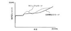
スポーツ走行モードではマニュアルモードより高めのエンジン回転数で力強い走りが可能にしており、低燃費走行モードではスポーツ走行モードとは逆にマニュアルモードより低いエンジン回転数での走りを実現するように設定している。図10および図11に低燃費走行モードおよびスポーツ走行モードの変速特性の一例をそれぞれ示す。 In sport driving mode, powerful driving is possible at a higher engine speed than in manual mode, and in low fuel consumption driving mode, it is set to realize driving at lower engine speed than in manual mode, contrary to sports driving mode. ing. FIGS. 10 and 11 show examples of shift characteristics in the low fuel consumption travel mode and the sport travel mode, respectively.
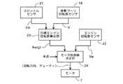
図1は、変速機制御装置(ECU17)の要部機能を示すブロック図である。目標エンジン回転数算出部23は、スロットル開度THと車速Vとに基づいて目標エンジン回転数Netgtを算出する。例えば、スロットル開度THと車速Vとの関数値として目標エンジン回転数Netgtを出力するマップで構成できる。このマップは走行モード毎に設けられる。車速Vは受動プーリ回転数センサ16で検出される受動プーリ10の回転数で代表させることができる。 FIG. 1 is a block diagram showing the main functions of the transmission control device (ECU 17). The target engine
モータ制御値決定部24は変速特性決定手段であり、目標エンジン回転数算出部23で算出された目標エンジン回転数Netgtとエンジン回転数センサ22で得られる実エンジン回転数Neとの差に基づいて、モータ7の回転方向およびモータ7のデューティつまりモータ回転速度を決定する。 The motor control
目標エンジン回転数Netgtが実エンジン回転数Neより高ければ、プーリレシオを大きくするために固定プーリ31と可動プーリ32との間隔を大きくする方向にモータ7を駆動する。また、目標エンジン回転数Netgtと実エンジン回転数Neとの差が車速に応じた判定値より大きい場合はプーリレシオの変更に要する時間を延長するために目標エンジン回転数Netgtを徐々に変更する。詳細はさらに後述する。モータ7はモータ制御値決定部24から出力された制御値つまりモータ7の回転方向およびデューティで、目標エンジン回転数Netgtに従って駆動され、プーリレシオが変更される。 If the target engine speed Netgt is higher than the actual engine speed Ne, the
従来の装置では、走行モードが切り替えられると、目標エンジン回転数Netgtが急激に変化してしまうために変速ショックが大きくなる。これに対して、本実施形態では、走行モードが切り替えられたときに目標エンジン回転数Netgtが徐々に変化するようにしているので変速ショックが低減される。 In the conventional apparatus, when the traveling mode is switched, the target engine speed Netgt changes abruptly, so that the shift shock increases. On the other hand, in the present embodiment, since the target engine speed Netgt is gradually changed when the travel mode is switched, the shift shock is reduced.
図3は、目標エンジン回転数Netgtを徐々に変化させる対策を講じないときの目標エンジン回転数Netgtの切り替わりの態様を示す図である。ラインAは走行モード切り替え前の目標エンジン回転数Netgtの特性であり、ラインBは走行モード切り替え後の目標エンジン回転数Netgtの特性である。 FIG. 3 is a diagram showing a mode of switching of the target engine speed Netgt when no measure for gradually changing the target engine speed Netgt is taken. Line A is a characteristic of the target engine speed Netgt before the travel mode is switched, and line B is a characteristic of the target engine speed Netgt after the travel mode is switched.
図4は、変速ショックの低減策を講じた例を示す図である。図示のように、走行モード切り替え時に、直ちに目標エンジン回転数NetgtをラインBに切り替えず、移行期間をかけてラインAからラインBへ徐々に目標エンジン回転数Netgtを更新させていく。これにより変速ショックを低減することができる。移行期間は走行モードと走行モード切り替え時点の走行モードや車速によって異ならせる(図7参照)。 FIG. 4 is a diagram illustrating an example in which a shift shock reduction measure is taken. As shown in the figure, at the time of switching the running mode, the target engine speed Netgt is not immediately switched to line B, but the target engine speed Netgt is gradually updated from line A to line B over a transition period. Thereby, the shift shock can be reduced. The transition period varies depending on the travel mode and the travel mode at the time of travel mode switching and the vehicle speed (see FIG. 7).
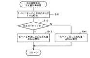
図5は、目標エンジン回転数Netgtを徐々に変化させる特性移行処理のフローチャートである。ステップS1では、モードスイッチ19が操作されたか、つまり走行モードの切り替えが行われたか否かが判定される。走行モードの切り替えが行われたならば、ステップS2に進んで、切り替え前の走行モード(現モード)と切り替え後の走行モード(移行先モード)における目標エンジン回転数Netgtの差ΔNetgtがしきい値(判定値)以上であるか否かが判別される。判定値は車速Vに応じて設定されているマップから読み出す。図6に車速と判定値との関係を示すマップの一例を示す。 FIG. 5 is a flowchart of a characteristic transition process for gradually changing the target engine speed Netgt. In step S1, it is determined whether or not the
目標エンジン回転数Netgtの差ΔNetgtが判定値より大きい場合はステップS3に進んで移行モードフラグがオンかオフかを判別する。移行モードフラグの初期値はオフである。したがって、最初の判別はオフであり、ステップS4に進んで移行モードフラグをオンにする。ステップS5では、移行期間中の目標エンジン回転数Netgtとして、現在の目標エンジン回転数Netgtに単位時間あたりの変化量を加算した値をセットする。 When the difference ΔNetgt in the target engine speed Netgt is larger than the determination value, the process proceeds to step S3 to determine whether the transition mode flag is on or off. The initial value of the transition mode flag is off. Therefore, the first determination is off, and the process proceeds to step S4 to turn on the transition mode flag. In step S5, a value obtained by adding the amount of change per unit time to the current target engine speed Netgt is set as the target engine speed Netgt during the transition period.
ステップS3で移行モードフラグがオンと判別された場合はステップS6に進んで、移行期間中の目標エンジン回転数Netgtとして、前回の目標エンジン回転数Netgtに単位時間あたりの変化量を加算した値をセットする。ステップS7では、ステップS5またはS6で計算された移行期間中の目標エンジン回転数Netgtを使って図2の機能に従った変速機制御を行う。 If it is determined in step S3 that the transition mode flag is on, the process proceeds to step S6, and the value obtained by adding the amount of change per unit time to the previous target engine speed Netgt as the target engine speed Netgt during the transition period. set. In step S7, transmission control according to the function of FIG. 2 is performed using the target engine speed Netgt during the transition period calculated in step S5 or S6.
なお、ステップS1またはステップS2の判定が否定であれば、ステップS8に進んで移行モードフラグをオフにする。ステップS9では、移行期間中のものではない、通常の目標エンジン回転数Netgt(例えば、前記線B)に従って変速機制御を行う。 If the determination in step S1 or step S2 is negative, the process proceeds to step S8 and the transition mode flag is turned off. In step S9, transmission control is performed according to a normal target engine speed Netgt (for example, the line B) that is not during the transition period.
なお、ステップS5,S6では、エンジン回転数変化量を加算したが、移行先の目標エンジン回転数Netgtの方が低い場合は、この加算に代えて減算を行う。 In steps S5 and S6, the engine speed change amount is added. If the target engine speed Netgt at the transfer destination is lower, subtraction is performed instead of this addition.
図7は、前記単位時間あたりの目標エンジン回転数Netgtの変化量の計算例を示すフローチャートである。この変化量によって移行期間が決定される。この計算例では、スロットル開度THの大小により、走行モードと車速Vとによって、または単に走行モードによって目標エンジン回転数Netgtの変化量を決定する。 FIG. 7 is a flowchart showing a calculation example of the amount of change in the target engine speed Netgt per unit time. The transition period is determined by the amount of change. In this calculation example, the amount of change in the target engine speed Netgt is determined by the travel mode and the vehicle speed V, or simply by the travel mode, depending on the magnitude of the throttle opening TH.
図7において、ステップS11では、スロットル開度THの比較値THvを計算する。比較値THvは走行モードと車速Vに基づいて計算される。例えば、車速Vとの関係でスロットル比較値THvを設定したマップを走行モード毎に設けておき、このマップを検索して比較値THvを求めることができる。 In FIG. 7, in step S11, a comparison value THv of the throttle opening TH is calculated. The comparison value THv is calculated based on the travel mode and the vehicle speed V. For example, a map in which the throttle comparison value THv is set in relation to the vehicle speed V is provided for each travel mode, and the map can be searched to obtain the comparison value THv.
ステップS12では、現在のスロットル開度THを比較値THvと比較する。スロットル開度THの方が小さいときはステップS13に進んで、走行モードと車速Vに応じた単位時間あたりの目標エンジン回転数変化量ΔNetgtを算出する。例えば、車速Vとの関係で、単位時間あたりの目標エンジン回転数変化量ΔNetgtを設定したマップを走行モード毎に設けておき、このマップを検索して単位時間あたりの目標エンジン回転数変化量ΔNetgtを求めることができる。 In step S12, the current throttle opening TH is compared with the comparison value THv. When the throttle opening TH is smaller, the routine proceeds to step S13, where the target engine speed change amount ΔNetgt per unit time according to the travel mode and the vehicle speed V is calculated. For example, a map in which the target engine speed change amount ΔNetgt per unit time is set in relation to the vehicle speed V is provided for each travel mode, and this map is searched to obtain the target engine speed change amount ΔNetgt per unit time. Can be requested.
ステップS12が否定の場合、つまりスロットル開度THの方が比較値THvより大きい場合はステップS14に進み、走行モードに応じて予め設定した単位時間あたりの目標エンジン回転数変化量ΔNetgtを読み出す。 If step S12 is negative, that is, if the throttle opening TH is larger than the comparison value THv, the process proceeds to step S14, and a target engine speed change amount ΔNetgt per unit time preset according to the travel mode is read.
図8はステップS11で使用する車速に応じたスロットル比較値THvを設定したマップの例を示す図である。マップは走行モード毎に設定される。 FIG. 8 is a diagram showing an example of a map in which a throttle comparison value THv corresponding to the vehicle speed used in step S11 is set. A map is set for each driving mode.
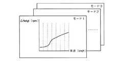
図9は、車速に応じた単位時間あたりの目標エンジン回転数変化量ΔNetgtを設定したマップの例を示す図である。このマップは走行モード毎に設定され、加算用および減算用にそれぞれ設けるのが望ましい。なお、加算用および減算用にそれぞれ異なるマップを使用することにより、移行期間の長さが異なる。例えば、加算用は減算用に比べて、車速に対応した単位時間あたりの目標エンジン回転数変化量ΔNetgtを短くする。 FIG. 9 is a diagram showing an example of a map in which the target engine speed change amount ΔNetgt per unit time according to the vehicle speed is set. This map is set for each traveling mode, and is preferably provided for addition and subtraction, respectively. Note that the length of the transition period is different by using different maps for addition and subtraction. For example, the target engine speed change amount ΔNetgt per unit time corresponding to the vehicle speed is made shorter for addition than for subtraction.
また、走行モード切り替え時のエンジン回転数Neに応じて、エンジン回転数Neが高いほど、移行時間が長くなるように、つまり単位時間あたりの目標エンジン回転数ΔNetgtを小さくするようにしてもよい。 Further, the target engine speed ΔNetgt per unit time may be decreased so that the transition time becomes longer as the engine speed Ne is higher in accordance with the engine speed Ne when the travel mode is switched.
1…無段変速機、 2…出力軸、 3…駆動プーリ、 10…受動プーリ、 14…Vベルト、 16…受動プーリ回転数センサ、 17…変速機制御ECU、 19…モードスイッチ、 21…スロットルセンサ、 22…エンジン回転数センサ、 23…目標エンジン回転数算出部、 24…モータ制御値決定部 DESCRIPTION OF SYMBOLS 1 ... Continuously variable transmission, 2 ... Output shaft, 3 ... Drive pulley, 10 ... Passive pulley, 14 ... V belt, 16 ... Passive pulley rotation speed sensor, 17 ... Transmission control ECU, 19 ... Mode switch, 21 ...
Claims (4)
Translated fromJapanese前記無段変速機の変速比変更用アクチュエータ(7)と、
スロットル開度(TH)と車速(V)との関数として目標エンジン回転数(Netgt)を出力する目標値出力手段(23)と、
前記目標エンジン回転数(Netgt)と実際のエンジン回転数(Ne)との差に基づいて前記アクチュエータ(7)の駆動方向および駆動速度を決定する変速特性決定手段(24)と、
前記モードスイッチ(19)によって走行モードが切り替えられたときに、切り替え前の走行モードと切り替え後の走行モードにおける目標エンジン回転数(Netgt)の差(ΔNetgt)が、車速に応じて予め設定されている判定値以上であるか否かを判別する手段とを具備し、
前記変速特性決定手段(24)が、走行モードの選択に伴って、現在の目標エンジン回転数(Netgt)が前記判定値を超えて変化することになると判断した場合に、現在の目標エンジン回転数(Netgt)を段階的に更新して走行モード切り替え後の値に移行させる変速特性移行手段を含んでいることを特徴とする無段変速機制御装置。The means (21) for detecting the throttle opening (TH), the means (16) for detecting the speed (V) of the vehicle equipped with the continuously variable transmission, and the output shaft (2) are connected to the continuously variable transmission. In a continuously variable transmission control devicehaving means (22) for detecting the engine speed (Ne) and a mode switch (19) for selecting a running mode ,
An actuator(7) for changing the gear ratio of thecontinuously variable transmission;
Target value output means(23) for outputting the target engine speed (Netgt) as a function of the throttle opening(TH) and the vehicle speed(V) ;
Shift characteristic determining means(24) for determining a driving direction and a driving speed of the actuator(7) based on a difference between the target engine speed(Netgt) and an actual engine speed(Ne);
When the travel mode is switched by the mode switch (19), the difference (ΔNetgt) between the target engine speed (Netgt) in the travel mode before switching and the travel mode after switching is preset according to the vehicle speed. Means for determining whether or not the determination value is equal to or greater than a certain determination value ,
When the shift characteristic determining means(24) determines that the current target engine speed(Netgt) will change beyond the determination value in accordance with the selection of the travel mode, the current target engine speed A continuously variable transmission control device comprising a shift characteristic shift means for updating(Netgt) stepwise to shift to a value after switching to a running mode.
前記変速特性移行手段(24)が、現在のスロットル開度(TH)が前記スロットル開度判定値(THv)より大きい場合は走行モードに応じて前記目標エンジン回転数(Netgt)を更新する一方、
現在のスロットル開度(TH)が前記スロットル開度判定値(THv)より小さい場合は走行モードと車速(V)に応じて前記目標エンジン回転数(Netgt)を更新するように構成されたことを特徴とする請求項1記載の無段変速機制御装置。Means for determining a throttle opening determination value(THv) set as a function of the running mode and the vehicle speed(V) ;
The shift characteristic transition means(24) updates the target engine speed(Netgt) according to the travel mode when the current throttle opening(TH) is larger than the throttle opening determination value(THv) ,
When the current throttle opening(TH) is smaller than the throttle opening determination value(THv), the target engine speed(Netgt) is updated according to the travel mode and the vehicle speed(V). The continuously variable transmission control device according to claim 1.
Priority Applications (7)
| Application Number | Priority Date | Filing Date | Title |
|---|---|---|---|
| JP2005191626AJP4641222B2 (en) | 2005-06-30 | 2005-06-30 | Continuously variable transmission control device |
| TW095117340ATW200706781A (en) | 2005-06-30 | 2006-05-16 | Continuously variable transmission controller |
| CN2006100887398ACN1892075B (en) | 2005-06-30 | 2006-06-05 | CVT control unit |
| IT000415AITTO20060415A1 (en) | 2005-06-30 | 2006-06-08 | CONTROL DEVICE FOR A CONTINUOUS VARIATION OF TRANSMISSION. |
| KR1020060051723AKR100810552B1 (en) | 2005-06-30 | 2006-06-09 | Controller for continuously variable transmission |
| DE102006029673ADE102006029673A1 (en) | 2005-06-30 | 2006-06-28 | Control device of a continuously variable transmission |
| US11/476,648US7559872B2 (en) | 2005-06-30 | 2006-06-29 | Continuously variable transmission controller |
Applications Claiming Priority (1)
| Application Number | Priority Date | Filing Date | Title |
|---|---|---|---|
| JP2005191626AJP4641222B2 (en) | 2005-06-30 | 2005-06-30 | Continuously variable transmission control device |
Publications (2)
| Publication Number | Publication Date |
|---|---|
| JP2007010045A JP2007010045A (en) | 2007-01-18 |
| JP4641222B2true JP4641222B2 (en) | 2011-03-02 |
Family
ID=37545255
Family Applications (1)
| Application Number | Title | Priority Date | Filing Date |
|---|---|---|---|
| JP2005191626AExpired - Fee RelatedJP4641222B2 (en) | 2005-06-30 | 2005-06-30 | Continuously variable transmission control device |
Country Status (7)
| Country | Link |
|---|---|
| US (1) | US7559872B2 (en) |
| JP (1) | JP4641222B2 (en) |
| KR (1) | KR100810552B1 (en) |
| CN (1) | CN1892075B (en) |
| DE (1) | DE102006029673A1 (en) |
| IT (1) | ITTO20060415A1 (en) |
| TW (1) | TW200706781A (en) |
Families Citing this family (48)
| Publication number | Priority date | Publication date | Assignee | Title |
|---|---|---|---|---|
| US7011600B2 (en) | 2003-02-28 | 2006-03-14 | Fallbrook Technologies Inc. | Continuously variable transmission |
| WO2006041718A2 (en)* | 2004-10-05 | 2006-04-20 | Fallbrook Technologies, Inc. | Continuously variable transmission |
| WO2007070167A2 (en) | 2005-10-28 | 2007-06-21 | Fallbrook Technologies Inc. | Electromotive drives |
| PL1954959T3 (en) | 2005-11-22 | 2013-10-31 | Fallbrook Ip Co Llc | Continuously variable transmission |
| CN102221073B (en) | 2005-12-09 | 2013-03-27 | 福博科技术公司 | Continuously variable transmission |
| EP1811202A1 (en)* | 2005-12-30 | 2007-07-25 | Fallbrook Technologies, Inc. | A continuously variable gear transmission |
| US7882762B2 (en)* | 2006-01-30 | 2011-02-08 | Fallbrook Technologies Inc. | System for manipulating a continuously variable transmission |
| WO2007106874A2 (en)* | 2006-03-14 | 2007-09-20 | Autocraft Industries, Inc. | Improved wheelchair |
| CN102269055B (en) | 2006-06-26 | 2013-08-28 | 福博科技术公司 | Continuously variable transmission |
| PL2089642T3 (en) | 2006-11-08 | 2013-09-30 | Fallbrook Ip Co Llc | Clamping force generator |
| EP2125469A2 (en) | 2007-02-01 | 2009-12-02 | Fallbrook Technologies Inc. | System and methods for control of transmission and/or prime mover |
| US20100093479A1 (en) | 2007-02-12 | 2010-04-15 | Fallbrook Technologies Inc. | Continuously variable transmissions and methods therefor |
| TWI461615B (en) | 2007-02-16 | 2014-11-21 | Fallbrook Ip Co Llc | Infinitely variable transmissions, continuously variable transmissions, methods, assemblies, subassemblies, and components therefor |
| EP2142826B1 (en)* | 2007-04-24 | 2015-10-28 | Fallbrook Intellectual Property Company LLC | Electric traction drives |
| US8641577B2 (en) | 2007-06-11 | 2014-02-04 | Fallbrook Intellectual Property Company Llc | Continuously variable transmission |
| CN103697120B (en) | 2007-07-05 | 2017-04-12 | 福博科技术公司 | Continuously variable transmission |
| CN103939602B (en) | 2007-11-16 | 2016-12-07 | 福博科知识产权有限责任公司 | Controllers for variable speed drives |
| US8321097B2 (en) | 2007-12-21 | 2012-11-27 | Fallbrook Intellectual Property Company Llc | Automatic transmissions and methods therefor |
| JP5173459B2 (en)* | 2008-01-31 | 2013-04-03 | 本田技研工業株式会社 | Shift control method for continuously variable transmission |
| US8313405B2 (en)* | 2008-02-29 | 2012-11-20 | Fallbrook Intellectual Property Company Llc | Continuously and/or infinitely variable transmissions and methods therefor |
| US8317651B2 (en) | 2008-05-07 | 2012-11-27 | Fallbrook Intellectual Property Company Llc | Assemblies and methods for clamping force generation |
| CN102112778B (en) | 2008-06-06 | 2013-10-16 | 福博科技术公司 | Infinitely variable transmission, continuously variable transmission, methods, assemblies, subassemblies and components therefor |
| EP2304272B1 (en) | 2008-06-23 | 2017-03-08 | Fallbrook Intellectual Property Company LLC | Continuously variable transmission |
| US8118706B2 (en)* | 2008-06-30 | 2012-02-21 | Caterpillar Inc. | Machine having a multiple-ratio transmission |
| CA2732668C (en) | 2008-08-05 | 2017-11-14 | Fallbrook Technologies Inc. | Methods for control of transmission and prime mover |
| US8469856B2 (en) | 2008-08-26 | 2013-06-25 | Fallbrook Intellectual Property Company Llc | Continuously variable transmission |
| US8167759B2 (en) | 2008-10-14 | 2012-05-01 | Fallbrook Technologies Inc. | Continuously variable transmission |
| ES2439647T3 (en) | 2009-04-16 | 2014-01-24 | Fallbrook Intellectual Property Company Llc | Stator set and speed change mechanism for a continuously variable transmission |
| US8543302B2 (en)* | 2009-05-15 | 2013-09-24 | Toyota Jidosha Kabushiki Kaisha | Gear shift control apparatus for automatic transmission and gear shift control method for automatic transmission |
| CA2727789A1 (en)* | 2009-12-23 | 2011-06-23 | Hubert Roberge | Electronically controlled continuously variable transmission with torque limiting system and method thereof |
| US8512195B2 (en)* | 2010-03-03 | 2013-08-20 | Fallbrook Intellectual Property Company Llc | Infinitely variable transmissions, continuously variable transmissions, methods, assemblies, subassemblies, and components therefor |
| US8888643B2 (en) | 2010-11-10 | 2014-11-18 | Fallbrook Intellectual Property Company Llc | Continuously variable transmission |
| JP5285684B2 (en)* | 2010-12-16 | 2013-09-11 | 富士重工業株式会社 | Control device for continuously variable transmission |
| AU2012240435B2 (en) | 2011-04-04 | 2016-04-28 | Fallbrook Intellectual Property Company Llc | Auxiliary power unit having a continuously variable transmission |
| JP5687346B2 (en)* | 2011-08-09 | 2015-03-18 | 本田技研工業株式会社 | Clamping pressure control device for continuously variable transmission |
| US8682550B2 (en) | 2011-10-14 | 2014-03-25 | Polaris Industries Inc. | Primary clutch electronic CVT |
| CN104302949B (en) | 2012-01-23 | 2017-05-03 | 福博科知识产权有限责任公司 | Infinitely variable continuously variable transmission, continuously variable continuously variable transmission, method, assembly, subassembly, and parts thereof |
| KR102433297B1 (en) | 2013-04-19 | 2022-08-16 | 폴브룩 인텔렉츄얼 프로퍼티 컴퍼니 엘엘씨 | Continuously variable transmission |
| JP5867519B2 (en) | 2014-01-15 | 2016-02-24 | トヨタ自動車株式会社 | vehicle |
| US10648554B2 (en) | 2014-09-02 | 2020-05-12 | Polaris Industries Inc. | Continuously variable transmission |
| US9759313B2 (en)* | 2014-11-26 | 2017-09-12 | Polaris Industries Inc. | Electronic shifting of a transmission |
| US9746070B2 (en) | 2014-11-26 | 2017-08-29 | Polaris Industries Inc. | Electronic control of a transmission |
| US10047861B2 (en) | 2016-01-15 | 2018-08-14 | Fallbrook Intellectual Property Company Llc | Systems and methods for controlling rollback in continuously variable transmissions |
| KR102364407B1 (en) | 2016-03-18 | 2022-02-16 | 폴브룩 인텔렉츄얼 프로퍼티 컴퍼니 엘엘씨 | continuously variable transmission system and method |
| US10023266B2 (en) | 2016-05-11 | 2018-07-17 | Fallbrook Intellectual Property Company Llc | Systems and methods for automatic configuration and automatic calibration of continuously variable transmissions and bicycles having continuously variable transmissions |
| WO2019183051A1 (en) | 2018-03-19 | 2019-09-26 | Polaris Industries Inc. | Continuously variable transmission |
| US11215268B2 (en) | 2018-11-06 | 2022-01-04 | Fallbrook Intellectual Property Company Llc | Continuously variable transmissions, synchronous shifting, twin countershafts and methods for control of same |
| WO2020176392A1 (en) | 2019-02-26 | 2020-09-03 | Fallbrook Intellectual Property Company Llc | Reversible variable drives and systems and methods for control in forward and reverse directions |
Family Cites Families (18)
| Publication number | Priority date | Publication date | Assignee | Title |
|---|---|---|---|---|
| JPH086797B2 (en)* | 1986-07-15 | 1996-01-29 | 本田技研工業株式会社 | Shift control method for continuously variable transmission for vehicle |
| JP2697828B2 (en)* | 1987-08-28 | 1998-01-14 | 株式会社日立製作所 | Automatic transmission for vehicles |
| JP2920976B2 (en)* | 1989-12-28 | 1999-07-19 | 日産自動車株式会社 | Transmission control device for continuously variable transmission |
| JP2752012B2 (en)* | 1991-06-14 | 1998-05-18 | 本田技研工業株式会社 | Shift control method for continuously variable transmission for vehicle |
| JPH06123351A (en)* | 1992-10-09 | 1994-05-06 | Aichi Mach Ind Co Ltd | Speed change control method |
| JPH08178042A (en)* | 1994-12-27 | 1996-07-12 | Nissan Motor Co Ltd | Shift control device for continuously variable transmission |
| JP3487988B2 (en)* | 1995-10-31 | 2004-01-19 | 株式会社日立ユニシアオートモティブ | Transmission control device for automatic transmission |
| JP3633063B2 (en)* | 1995-11-07 | 2005-03-30 | マツダ株式会社 | Control device for automatic transmission |
| JPH09196158A (en) | 1996-01-24 | 1997-07-29 | Nissan Motor Co Ltd | Transmission control device for automatic transmission |
| JP3218962B2 (en) | 1996-01-24 | 2001-10-15 | 日産自動車株式会社 | Transmission control device for continuously variable transmission |
| KR100308960B1 (en) | 1997-12-17 | 2002-02-19 | 이계안 | Transmission control device and method of automatic transmission |
| US6066070A (en) | 1998-04-28 | 2000-05-23 | Toyota Jidosha Kabushiki Kaisha | Control system of vehicle having continuously variable transmission |
| JP3402218B2 (en)* | 1998-09-25 | 2003-05-06 | 日産自動車株式会社 | Transmission control device for automatic transmission |
| JP3659093B2 (en)* | 1999-11-05 | 2005-06-15 | 日産自動車株式会社 | Shift control device for continuously variable transmission |
| JP2002081534A (en) | 2000-09-04 | 2002-03-22 | Bando Chem Ind Ltd | Transmission control device for vehicles |
| JP3607640B2 (en) | 2001-06-18 | 2005-01-05 | 本田技研工業株式会社 | Hydraulic control device for transmission |
| JP3653028B2 (en) | 2001-10-17 | 2005-05-25 | 本田技研工業株式会社 | Power transmission control device for vehicle |
| JP3794483B2 (en)* | 2002-06-05 | 2006-07-05 | 本田技研工業株式会社 | Control device for continuously variable transmission for vehicle |
- 2005
- 2005-06-30JPJP2005191626Apatent/JP4641222B2/ennot_activeExpired - Fee Related
- 2006
- 2006-05-16TWTW095117340Apatent/TW200706781A/ennot_activeIP Right Cessation
- 2006-06-05CNCN2006100887398Apatent/CN1892075B/ennot_activeExpired - Fee Related
- 2006-06-08ITIT000415Apatent/ITTO20060415A1/enunknown
- 2006-06-09KRKR1020060051723Apatent/KR100810552B1/ennot_activeExpired - Fee Related
- 2006-06-28DEDE102006029673Apatent/DE102006029673A1/ennot_activeWithdrawn
- 2006-06-29USUS11/476,648patent/US7559872B2/ennot_activeExpired - Fee Related
Also Published As
| Publication number | Publication date |
|---|---|
| JP2007010045A (en) | 2007-01-18 |
| TWI304460B (en) | 2008-12-21 |
| KR100810552B1 (en) | 2008-03-18 |
| KR20070003560A (en) | 2007-01-05 |
| CN1892075A (en) | 2007-01-10 |
| ITTO20060415A1 (en) | 2007-01-01 |
| DE102006029673A1 (en) | 2007-01-04 |
| US7559872B2 (en) | 2009-07-14 |
| CN1892075B (en) | 2011-01-19 |
| TW200706781A (en) | 2007-02-16 |
| US20070004552A1 (en) | 2007-01-04 |
Similar Documents
| Publication | Publication Date | Title |
|---|---|---|
| JP4641222B2 (en) | Continuously variable transmission control device | |
| JP5173459B2 (en) | Shift control method for continuously variable transmission | |
| JP3293531B2 (en) | Control device for continuously variable transmission | |
| US8620554B2 (en) | Accelerator reaction force control apparatus | |
| US7108634B2 (en) | Apparatus and method for controlling clutch of mechanical automatic transmission | |
| RU2660235C2 (en) | Vehicle operation method (embodiments) | |
| JP2008239130A (en) | Control device for vehicle | |
| US8965647B2 (en) | Control apparatus for continuously variable transmission | |
| KR100795248B1 (en) | Vehicle control | |
| JP4386508B2 (en) | Control method of hydrostatic continuously variable transmission | |
| CN108374887B (en) | Vehicle control device | |
| CN100560962C (en) | Control system and continuously variable transmission control method for belt-type continuously variable transmission | |
| JPH07158706A (en) | Speed change control in v-belt type continuously variable transmission | |
| JP2011027200A (en) | Control device for vehicle | |
| JP3979908B2 (en) | Control method of automatic transmission | |
| CN108603452B (en) | Method and device for operating a drive and drive | |
| JP3724336B2 (en) | Shift control device for automatic transmission | |
| KR20190066875A (en) | Cvt control method for vehicle on winding road | |
| JP4158152B2 (en) | Variable valve control system for engine | |
| JP2010121696A (en) | Controller of stepless speed change drive | |
| JP2002286128A (en) | Shift range changing control device for automatic transmission | |
| JP2007022255A (en) | Vehicle control device | |
| US8088037B2 (en) | Straddle type vehicle, power unit and continuously variable transmission | |
| JPH0826001A (en) | Vehicle control device | |
| JPS6095260A (en) | Electronically controlled continuously variable transmission |
Legal Events
| Date | Code | Title | Description |
|---|---|---|---|
| A621 | Written request for application examination | Free format text:JAPANESE INTERMEDIATE CODE: A621 Effective date:20071127 | |
| A977 | Report on retrieval | Free format text:JAPANESE INTERMEDIATE CODE: A971007 Effective date:20100514 | |
| A131 | Notification of reasons for refusal | Free format text:JAPANESE INTERMEDIATE CODE: A131 Effective date:20100519 | |
| A521 | Request for written amendment filed | Free format text:JAPANESE INTERMEDIATE CODE: A523 Effective date:20100715 | |
| TRDD | Decision of grant or rejection written | ||
| A01 | Written decision to grant a patent or to grant a registration (utility model) | Free format text:JAPANESE INTERMEDIATE CODE: A01 Effective date:20101124 | |
| A01 | Written decision to grant a patent or to grant a registration (utility model) | Free format text:JAPANESE INTERMEDIATE CODE: A01 | |
| A61 | First payment of annual fees (during grant procedure) | Free format text:JAPANESE INTERMEDIATE CODE: A61 Effective date:20101126 | |
| R150 | Certificate of patent or registration of utility model | Ref document number:4641222 Country of ref document:JP Free format text:JAPANESE INTERMEDIATE CODE: R150 Free format text:JAPANESE INTERMEDIATE CODE: R150 | |
| FPAY | Renewal fee payment (event date is renewal date of database) | Free format text:PAYMENT UNTIL: 20131210 Year of fee payment:3 | |
| LAPS | Cancellation because of no payment of annual fees |