JP4639749B2 - Manufacturing method of golf club head - Google Patents
Manufacturing method of golf club headDownload PDFInfo
- Publication number
- JP4639749B2 JP4639749B2JP2004305910AJP2004305910AJP4639749B2JP 4639749 B2JP4639749 B2JP 4639749B2JP 2004305910 AJP2004305910 AJP 2004305910AJP 2004305910 AJP2004305910 AJP 2004305910AJP 4639749 B2JP4639749 B2JP 4639749B2
- Authority
- JP
- Japan
- Prior art keywords
- metal
- golf club
- club head
- crown portion
- crown
- Prior art date
- Legal status (The legal status is an assumption and is not a legal conclusion. Google has not performed a legal analysis and makes no representation as to the accuracy of the status listed.)
- Expired - Fee Related
Links
Images


Classifications
- A—HUMAN NECESSITIES
- A63—SPORTS; GAMES; AMUSEMENTS
- A63B—APPARATUS FOR PHYSICAL TRAINING, GYMNASTICS, SWIMMING, CLIMBING, OR FENCING; BALL GAMES; TRAINING EQUIPMENT
- A63B53/00—Golf clubs
- A63B53/04—Heads
- A63B53/0437—Heads with special crown configurations
- A—HUMAN NECESSITIES
- A63—SPORTS; GAMES; AMUSEMENTS
- A63B—APPARATUS FOR PHYSICAL TRAINING, GYMNASTICS, SWIMMING, CLIMBING, OR FENCING; BALL GAMES; TRAINING EQUIPMENT
- A63B53/00—Golf clubs
- A63B53/04—Heads
- A63B53/0466—Heads wood-type
- A—HUMAN NECESSITIES
- A63—SPORTS; GAMES; AMUSEMENTS
- A63B—APPARATUS FOR PHYSICAL TRAINING, GYMNASTICS, SWIMMING, CLIMBING, OR FENCING; BALL GAMES; TRAINING EQUIPMENT
- A63B53/00—Golf clubs
- A63B53/04—Heads
- A63B53/0408—Heads characterised by specific dimensions, e.g. thickness
- A—HUMAN NECESSITIES
- A63—SPORTS; GAMES; AMUSEMENTS
- A63B—APPARATUS FOR PHYSICAL TRAINING, GYMNASTICS, SWIMMING, CLIMBING, OR FENCING; BALL GAMES; TRAINING EQUIPMENT
- A63B53/00—Golf clubs
- A63B53/04—Heads
- A63B53/0416—Heads having an impact surface provided by a face insert
- A—HUMAN NECESSITIES
- A63—SPORTS; GAMES; AMUSEMENTS
- A63B—APPARATUS FOR PHYSICAL TRAINING, GYMNASTICS, SWIMMING, CLIMBING, OR FENCING; BALL GAMES; TRAINING EQUIPMENT
- A63B53/00—Golf clubs
- A63B53/04—Heads
- A63B53/0433—Heads with special sole configurations
- A—HUMAN NECESSITIES
- A63—SPORTS; GAMES; AMUSEMENTS
- A63B—APPARATUS FOR PHYSICAL TRAINING, GYMNASTICS, SWIMMING, CLIMBING, OR FENCING; BALL GAMES; TRAINING EQUIPMENT
- A63B53/00—Golf clubs
- A63B53/04—Heads
- A63B53/047—Heads iron-type
- A—HUMAN NECESSITIES
- A63—SPORTS; GAMES; AMUSEMENTS
- A63B—APPARATUS FOR PHYSICAL TRAINING, GYMNASTICS, SWIMMING, CLIMBING, OR FENCING; BALL GAMES; TRAINING EQUIPMENT
- A63B60/00—Details or accessories of golf clubs, bats, rackets or the like
- A63B60/50—Details or accessories of golf clubs, bats, rackets or the like with through-holes
- A—HUMAN NECESSITIES
- A63—SPORTS; GAMES; AMUSEMENTS
- A63B—APPARATUS FOR PHYSICAL TRAINING, GYMNASTICS, SWIMMING, CLIMBING, OR FENCING; BALL GAMES; TRAINING EQUIPMENT
- A63B2102/00—Application of clubs, bats, rackets or the like to the sporting activity ; particular sports involving the use of balls and clubs, bats, rackets, or the like
- A63B2102/32—Golf
- A—HUMAN NECESSITIES
- A63—SPORTS; GAMES; AMUSEMENTS
- A63B—APPARATUS FOR PHYSICAL TRAINING, GYMNASTICS, SWIMMING, CLIMBING, OR FENCING; BALL GAMES; TRAINING EQUIPMENT
- A63B2209/00—Characteristics of used materials
- A—HUMAN NECESSITIES
- A63—SPORTS; GAMES; AMUSEMENTS
- A63B—APPARATUS FOR PHYSICAL TRAINING, GYMNASTICS, SWIMMING, CLIMBING, OR FENCING; BALL GAMES; TRAINING EQUIPMENT
- A63B2209/00—Characteristics of used materials
- A63B2209/02—Characteristics of used materials with reinforcing fibres, e.g. carbon, polyamide fibres
- A63B2209/023—Long, oriented fibres, e.g. wound filaments, woven fabrics, mats
Landscapes
- Health & Medical Sciences (AREA)
- General Health & Medical Sciences (AREA)
- Physical Education & Sports Medicine (AREA)
- Life Sciences & Earth Sciences (AREA)
- Engineering & Computer Science (AREA)
- Wood Science & Technology (AREA)
- Golf Clubs (AREA)
Description
Translated fromJapanese本発明は、中空ゴルフクラブヘッドの製造方法に係り、特にウッド型又はそれに近似した形状のゴルフクラブヘッドの製造方法に関するものである。The present invention relates toa method of manufacturing a hollow golf club head, and more particularly to a manufacturing methodof a wood-type or the approximate shape golf clubheads of.
ドライバーやフェアウェーウッドなどのウッド型ゴルフクラブヘッドとして、中空の金属製のものが広く用いられている。一般に、中空のウッド型のゴルフクラブヘッドは、ボールをヒットするためのフェース部と、ゴルフクラブヘッドの上面部を構成するクラウン部と、ゴルフクラブヘッドの底面部を構成するソール部と、ゴルフクラブヘッドのトウ側、リヤ側及びヒール側の側面部を構成するサイド部と、ホゼル部とを有している。このホゼル部にシャフトが挿入され、接着剤等によって固定される。なお、最近では、ユーティリティクラブと称されるゴルフクラブも多く市販されており、このユーティリティゴルフクラブの1種として、上記ウッド型ゴルフクラブヘッドに類似した(即ち、フェース部、ソール部、サイド部及びクラウン部並びにホゼル部を有した)ヘッドを有するゴルフクラブも各種市販されている。 Hollow metal golf club heads such as drivers and fairway woods are widely used. In general, a hollow wood-type golf club head includes a face portion for hitting a ball, a crown portion constituting an upper surface portion of the golf club head, a sole portion constituting a bottom surface portion of the golf club head, and a golf club. The head portion includes side portions constituting side portions on the toe side, rear side, and heel side of the head, and a hosel portion. A shaft is inserted into the hosel part and fixed with an adhesive or the like. Recently, many golf clubs referred to as utility clubs are also commercially available, and one type of utility golf club is similar to the wood-type golf club head (that is, the face portion, the sole portion, the side portion, and the like). Various golf clubs having a head (having a crown portion and a hosel portion) are also commercially available.
この中空ゴルフクラブヘッドを構成する金属としては、アルミニウム合金、ステンレスやチタン合金が用いられているが、近年は特にチタン合金が広く用いられている。 As a metal constituting the hollow golf club head, an aluminum alloy, stainless steel, or titanium alloy is used, but in recent years, a titanium alloy is particularly widely used.
中空ゴルフクラブヘッドの体積を大きくすることにより、スイートスポットを拡大することが可能となる。体積を大きくすることに伴うゴルフクラブヘッドの重量増加を防ぐために、ゴルフクラブヘッドの構成材として、上記金属よりもさらに比重が小さい繊維強化樹脂を採用することが考えられている。この場合、ボールをヒットするフェース面は、強度を確保するために金属製とする必要があるので、フェース部以外の部分を繊維強化樹脂製とすることになる。 The sweet spot can be enlarged by increasing the volume of the hollow golf club head. In order to prevent an increase in weight of the golf club head due to an increase in volume, it is considered to employ a fiber reinforced resin having a specific gravity smaller than that of the metal as a constituent material of the golf club head. In this case, since the face surface that hits the ball needs to be made of metal in order to ensure strength, the portion other than the face portion is made of fiber reinforced resin.
特開2004−16654号には、クラウン部と、トウ側及びヒール側のサイド部とを炭素繊維強化熱硬化性樹脂(CFRP)製とし、ソール部の主要部と、フェース部と、クラウン部及びサイド部の前縁部とを金属製としたゴルフクラブヘッドが記載されている。このゴルフクラブヘッドでは、クラウン部及びサイド部の前縁部を構成する金属クラウン部及び金属サイド部の内面にCFRP体が接合されている。このゴルフクラブヘッドを製造する場合、金属クラウン部の内面(下面)にCFRP用のプリプレグシートを重ねて加熱加圧する。
金属クラウン部の内面(下面)にプリプレグシートを重ねて接合する場合、プリプレグシートを金属クラウン部に仮付けして動かないようにしておくことが好ましい。この仮付けのためには、粘着性を有した樹脂をプリプレグシートと金属クラウン部との間に介在させるのが好ましいが、加熱加圧するときにこの粘着性樹脂の粘度が低下して流れてしまうおそれがある。 When the prepreg sheet is overlapped and joined to the inner surface (lower surface) of the metal crown portion, it is preferable that the prepreg sheet is temporarily attached to the metal crown portion so as not to move. For this temporary attachment, it is preferable to interpose an adhesive resin between the prepreg sheet and the metal crown portion, but when heated and pressurized, the viscosity of the adhesive resin decreases and flows. There is a fear.
本発明は、かかる問題点を解消し、金属クラウン部と繊維強化樹脂体とを容易に接合一体化することができるゴルフクラブヘッドの製造方法を提供することを目的とする。The present invention is to solve the above problems, and an object thereof is to provide a methodof manufacturinga golf clubheads that can be easily bonded integrate the metal crown portion and a fiber reinforced resin body.
本発明(請求項1)のゴルフクラブヘッドの製造方法は、フェース部、ソール部、サイド部、クラウン部及びホゼル部を有し、該クラウン部の主要部が繊維強化樹脂体よりなり、少なくともフェース部と、該フェース部に連なる、クラウン部の前縁部とが金属製であり、該クラウン部の前縁部を構成する金属クラウン部の上面に凹部が設けられ、該金属クラウン部の上面に対し該繊維強化樹脂体の前縁部が重なって結合されており、該金属クラウン部の凹部は、深さが0.1〜0.3mmである凹穴であり、該金属クラウン部の全体にわたって10〜200個設けられているゴルフクラブヘッドを製造する方法であって、該金属クラウン部の上面の凹部に粘着性を有した熱硬化性樹脂を付着させておき、該金属クラウン部の上面に対して前記繊維強化樹脂体の前縁部を重ねて加熱加圧することを特徴とするものである。Method of manufacturing a golf club head of the present invention (claim 1), a face portion, sole portion, side portion,have a crown portion and a hoselportion, the main portion of the crown portion is made of fiber reinforced resin material, at least the face parts and, connected to the face portion,Ri is metallic der a front edge portion of the crown portion, the recess is provided on the upper surface of the metal crown portion constituting the front edge of the crown portion, the upper surface of the metal crown portion The front edge portion of the fiber reinforced resin body is overlapped and bonded, and the concave portion of the metal crown portion is a concave hole having a depth of 0.1 to 0.3 mm, and the entire metal crown portion overa 10 to 200 amino provided theyprocess for producingLugo Ruff clubhead, allowed to adhere a thermosetting resin having an adhesiveness in the recess of the upper surface of the metal crown portion, of the metal crown portion Said to the upper surface It is characterized in that the heating and pressing repeatedly the front edge of the fiber-reinforced resin body.
本発明により製造されるゴルフクラブヘッドにあっては、繊維強化樹脂体が金属クラウン部の上面に重なっており、この金属クラウン部に凹部が設けられている。そのため、粘着性樹脂を金属クラウン部と繊維強化樹脂体形成用プリプレグシートとの間に介在させて加熱加圧した際に該粘着性樹脂が凹部に引っ掛かる如くして流れ出さなくなる。即ち、凹部が粘着性樹脂のアンカー作用を奏するようになる。In the golf club headmanufactured according to the present invention, the fiber reinforced resin body overlaps the upper surface of the metal crown portion, and a recess is provided in the metal crown portion. Therefore, when the adhesive resin is interposed between the metal crown portion and the prepreg sheet for forming the fiber reinforced resin body and heated and pressurized, the adhesive resin does not flow out as if it is caught in the recess. That is, the concave portion exhibits an anchoring action of the adhesive resin.
これにより、粘着性樹脂を金属クラウン部とプリプレグシートとの間に確実に介在させて両者を結合させることが可能となる。 Thus, the adhesive resin can be reliably interposed between the metal crown portion and the prepreg sheet to bond the two.
なお、本発明では、上記凹部を、ゴルフクラブヘッド製品の繊維強化樹脂体と金属クラウン部との結合力を高めるアンカー部としても機能させることもでき、ゴルフクラブヘッドの強度、耐久性が向上する。In the present invention, the concave portion can also function as an anchor portion that enhances the bonding force between the fiber reinforced resin body of the golf club head product and the metal crown portion, thereby improving the strength and durability of the golf club head..
以下、図面を参照して実施の形態について説明する。第1図は実施の形態に係るゴルフクラブヘッドの斜視図、第2図はこのゴルフクラブヘッドの金属体の前方からの斜視図、第3図は金属体の後方からの斜視図、第4図は金属体のヒール側からの側面図、第5図は金属体の平面図、第6図(a)は金属体のソール側からの斜視図、第6図(b),(c)は第6図(a)のB−B線、C−C線断面図、第7図は金属体へのウェイト材の取り付けを説明する分解斜視図、第8図(a)はゴルフクラブヘッドのソール側からの斜視図、第8図(b),(c)は第8図(a)のB−B線、C−C線断面図、第8図(d)は同(c)のD部の拡大図、第9図は第1図のIX−IX線断面図である。 Hereinafter, embodiments will be described with reference to the drawings. 1 is a perspective view of a golf club head according to an embodiment, FIG. 2 is a perspective view from the front of the metal body of the golf club head, FIG. 3 is a perspective view from the rear of the metal body, and FIG. Is a side view from the heel side of the metal body, FIG. 5 is a plan view of the metal body, FIG. 6 (a) is a perspective view from the sole side of the metal body, and FIGS. 6 (b) and 6 (c) are 6A is a cross-sectional view taken along line BB and CC in FIG. 6, FIG. 7 is an exploded perspective view illustrating attachment of a weight material to a metal body, and FIG. 8A is a sole side of a golf club head. FIGS. 8 (b) and 8 (c) are cross-sectional views taken along line BB and CC in FIG. 8 (a), and FIG. 8 (d) is a cross-sectional view of portion D in FIG. 8 (c). FIG. 9 is an enlarged view, and FIG. 9 is a sectional view taken along line IX-IX in FIG.
このゴルフクラブヘッド1は、フェース部2、ソール部3、サイド部4、クラウン部5及びホゼル部6を有した中空ウッド型ゴルフクラブヘッドである。 This
フェース部2はボールをヒットする面であり、図示はしないが溝(スコアライン)が設けられている。ソール部3はゴルフクラブヘッドの底面部を構成し、サイド部4はトウ側及びヒール側並びに後面側の側面部を構成している。クラウン部5はゴルフクラブヘッドの上面部を構成している。ホゼル部6には、シャフトが差し込まれ、接着剤により該シャフトが固着される。 The
このゴルフクラブヘッド1は金属体10と、繊維強化樹脂体(以下、FRP体という。)30とからなる。 The
金属体10は、フェース部2と、金属ソール部13と、金属サイド部(トウ)14と、金属クラウン部15と、金属サイド部(ヒール)16と、金属ソール部13の前部のトウ側及びヒール側にそれぞれ設けられた凹所17と、金属ソール部13の後部に設けられた環状部18と、ホゼル部6とを有する。 The
クラウン部5の前縁部を構成する金属クラウン部15は、金属サイド部(トウ)14及び金属サイド部(ヒール)16とに連なっている。金属サイド部(トウ)14及び金属サイド部(ヒール)16はそれぞれ金属ソール部13に連なっている。該金属クラウン部15、金属サイド部14,16及び金属ソール部13はフェース部2に連なっている。 The
金属クラウン部15は、トウ側からヒール側にかけて、上方に凸となるように滑らかに湾曲しており、この湾曲の曲率半径は好ましくは60〜150mm程度である。 The
この金属クラウン部15の上面には、該金属クラウン部15の略全領域にわたって、凹部としての浅い凹穴15aが設けられている。凹穴15aは円形であり、その直径は好ましくは0.1〜2.0mm特に0.3〜1.5mm、深さは0.1〜0.3mmである。凹穴15aの数は、10〜200個である。 A shallow
金属ソール部13の前部は、ゴルフクラブヘッドのトウ側からヒール側にまで跨る全幅状となっている。この金属ソール部13は、該前部から後方に向って徐々に細幅となっている。金属ソール部13の後部は、ゴルフクラブヘッドのヒール・トウ方向の中央部に配置されている。 The front portion of the metal
この金属ソール部13の前部のトウ側及びヒール側にそれぞれ浅い凹所17が設けられている。各凹所17は、トウ・ヒール方向に延在している。この凹所17を含む金属ソール部13の前部領域には、トウ・ヒール方向に延在した浅い溝部17aが設けられている。この溝部17aの前後方向幅は、トウ側及びヒール側で大であり、トウ・ヒール方向の中央付近で小となっている。溝部17aは、凹所17,17の周囲を取り巻くように設けられている。
各凹所17,17にそれぞれ第1のウェイト材20が収容され、各第1のウェイト材20を覆うように樹脂成形体よりなる樹脂プレート21が溝部21に嵌合配置されている。 A
この樹脂プレート21を覆うようにクロス繊維プリプレグの硬化体よりなるFRP層22が設けられている。このFRP層22は、後述の通り、FRP体30と一連一体となっている。 An
金属ソール部13の後部は、斜め後方に立ち上がっている。この金属ソール部13の後部に環状部18が一体化されている。この環状部18の内周面に雌ネジ(図示略)が設けられており、第7,8図の通り、ネジ状の第2のウェイト材25が螺じ込みされている。金属ソール部13には環状部18を取り巻く第1の円環形凹部18aと、該円環形凹部18aを取り巻く第2の円環形凹部18bとが設けられている。この第1の円環形凹部18aにアルミ製の円形プレート36が無理嵌め等により嵌合固着されている。 The rear portion of the metal
図示は省略するが、フェース部2は鍛造又はプレス成形により形成されたフェースプレートにより構成されている。金属体10のその他の部分は、鋳造により製造されている。この鋳造品は、フェース部が開口となっており、この開口にフェースプレートが嵌合され、カシメ、溶接などにより固着されている。 Although not shown, the
フェース部2は、その中央部が厚く、周縁部が薄い高反発の構成となっている。 The
FRP体30は、このゴルフクラブヘッド1の外面のその他の部分を構成している。即ち、FRP体30は、クラウン部5の略全体と、サイド部4の後半部と、ソール部3の金属ソール部13以外の部分を構成する大きさを有している。 The
第8,9図に拡大して示されるように、FRP体30は、金属クラウン部15、金属サイド部14(トウ、ヒール双方)及び金属ソール部13の外面に密着している。 As shown in enlarged views in FIGS. 8 and 9, the
クラウン部にあっては、FRP体30は、金属クラウン部15の上面の最前縁付近にまで延在している。サイド部のヒール側及びソール側にあっては、金属体10に段差部14a,16aが形成されており、FRP体30はこの段差部14a,16aに達するように設けられている。なお、段差部14a,16aはバック側の方が凹む段差となっている。 In the crown portion, the
このFRP体30を成形し且つ金属体10と一体化するには、ゴルフクラブヘッドの外形形状を有した金型を用意し、直交2方向に繊維を配向させた第1のプリプレグシート(未硬化の樹脂繊維複合シート)を該金型の内面に沿って配設する。この第1のプリプレグシートは、FRP体30の全外面の他に、さらに前記溝部17aを覆う位置に配置される。 In order to mold the
次に、この第1のプリプレグシートの上に、一方向に繊維を配向させた第2のプリプレグシートを複数枚重ねる。複数の第2のプリプレグシートは、繊維方向が交互となるように積層させる。 Next, a plurality of second prepreg sheets in which fibers are oriented in one direction are overlaid on the first prepreg sheet. The plurality of second prepreg sheets are laminated so that the fiber directions are alternate.
次に、第1のウェイト材20及び樹脂プレート21を装着してあるが、第2のウェイト材25及び円形プレート26は装着してない金属体10を金型内に配置する。 Next, the
この際、金属体10のうち金属クラウン部15等のプリプレグシートと重なる部分に、粘着性を有した樹脂(例えばエポキシ樹脂、ビニルエステル樹脂等を有機溶剤に溶解させた粘稠液)を付着させておく。なお、この樹脂としては120〜150℃の温度にて3〜15分で硬化する熱硬化性樹脂を用いる。At this time, an adhesive resin (for example, a viscous liquid in which an epoxy resin, a vinyl ester resin or the like is dissolved in an organic solvent) is attached to a portion of the
次に、この金属体10の金属ソール部13(ただし、溝部17aよりも後部側。また、環状部18を除く。)の内面に第3のプリプレグシートを重ねる。その後、環状部18の開口を通して内部にガス圧を加えた状態で加熱し、樹脂を硬化させる。この際、ゴルフクラブヘッド内にナイロン等の樹脂袋を配置しておき、この袋内にガスを供給して膨らませ、プリプレグシートを圧迫して金型内面に密着させてもよい。 Next, a third prepreg sheet is overlapped on the inner surface of the metal
これにより、第8図のようにFRP体30が成形されると共に、FRP体30の周縁部が金属体10に密着する。また、樹脂プレート21は第1のプリプレグシートの硬化物よりなるFRP層22で覆われる。成形終了後、脱型し、必要に応じゴルフクラブヘッドの内面に振動吸収層や打球音調整層を形成する。例えば、ポリイソブチレン等よりなる粘着剤を層状に形成することにより、ゴルフクラブヘッドのカラ鳴りが防止される。 As a result, the
次に、環状体18に第2のウェイト材25を螺じ込み、次いで、第1の円環形凹部18aにアルミ等の金属プレート26を嵌着する。その後、このゴルフクラブヘッドの外面に必要に応じ研磨や塗装を施し、ゴルフクラブヘッド製品とする。 Next, the
上記の加熱加圧工程においては、粘着性樹脂が金属体10の金属クラウン部15など、プリプレグシートと重なる箇所に付着されており、しかも金属クラウン部15には多数の凹穴15aが設けられているので、粘着性樹脂が熱によって低粘性になってもプリプレグシートと金属クラウン部15との間から流出することがない。このため、金属クラウン部15に対しFRP体30が適正に結合したゴルフクラブヘッド1が製造される。また、このゴルフクラブヘッドにあっては、多数の凹穴15aがFRP体30と金属クラウン部15との結合力を高めるアンカー部としても機能するので、ゴルフクラブヘッドの強度及び耐久性に優れる。なお、粘着性樹脂に由来する樹脂成分は硬化後に凹穴15a内に存在してもよく、プリプレグシートの樹脂中に吸収され、プリプレグシート由来の樹脂成分が凹穴15a内に存在してもよい。 In the heating and pressurizing step, the adhesive resin is attached to a portion overlapping the prepreg sheet such as the
このゴルフクラブヘッド1の好適なスペックについて次に説明する。 Next, preferred specifications of the
FRP体30の重量は、ゴルフクラブヘッド1の全体の重量の5〜30%特に10〜25%とりわけ15〜20%であることが好ましい。 The weight of the
ゴルフクラブヘッド1の重量は175〜250gが好適であり、ロフト角が13゜以下の場合は175〜200g程度が好適である。ウェイト材以外の金属体10の構成材料としては、チタン合金、ステンレス、マルエージング鋼、銅合金、ジルコニウム合金等が好適であるが、中でもTi−6Al−4Vなどのチタン合金が好適である。 The weight of the
なお、フェースプレートを鍛造又はプレス成形する場合、その材料はTi−6Al−4V,Ti−15V−3Cr−3Sn−3Al,Ti−22V−4Alなどのチタン合金(特にβ形のもの)が好ましい。なお、β形のものは、塑性加工後、熱処理して強度及び硬度を高くすることができる。 When the face plate is forged or press-molded, the material is preferably a titanium alloy such as Ti-6Al-4V, Ti-15V-3Cr-3Sn-3Al, Ti-22V-4Al (particularly β-type). Note that the β type can be heat-treated after plastic working to increase the strength and hardness.
鋳造を行う場合、インベストメント鋳造が好適である。薄肉部分にも溶湯が十分に行き渡るようにするために、真空鋳造や遠心鋳造を行うのが好ましい。 When casting, investment casting is preferred. It is preferable to perform vacuum casting or centrifugal casting so that the molten metal can be sufficiently distributed to the thin portion.
ウェイト材としては、比重が10以上好ましくは12以上のタングステンやタングステン合金が好適である。 As the weight material, tungsten or tungsten alloy having a specific gravity of 10 or more, preferably 12 or more is suitable.
なお、金属体がチタン合金の場合、ウェイト材として上記以外にもステンレス鋼、銅合金、鉛などを用いてもよい。 In addition, when a metal body is a titanium alloy, you may use stainless steel, a copper alloy, lead other than the above as a weight material.
第1のウェイト材20は、凹所17に対しカシメ、圧入、接着剤や粘着剤による付着により固定されてもよい。 The
第2のウェイト材25は、ろう付や溶接によって環状体18に固着されてもよい。 The
FRP体30等を成形するためのプリプレグとしては、クロス繊維プリプレグ、一方向繊維プリプレグ等のいずれでもよい。このプリプレグとしてSMCプリプレグを使用した場合には、肉薄のFRP体30を容易に形成することができる。 The prepreg for forming the
FRP体30は、プリプレグを3〜8枚程度積層して形成することが好ましい。 The
プリプレグ中の繊維としては弾性率が20×103〜30×103kg/mm2程度のカーボン繊維等が好適であるが、これに限定されない。The fiber in the prepreg is preferably a carbon fiber having an elastic modulus of about 20 × 103 to 30 × 103 kg / mm2 , but is not limited thereto.
この繊維の配向を調整することによりクラウン部における前後方向の弾性率をトウ・ヒール方向よりも低くすることができる。例えば、クロス繊維プリプレグと一方向繊維プリプレグとを交互に積層し、この一方向繊維プリプレグの繊維配向方向をトウ・ヒール方向とする。 By adjusting the orientation of the fiber, the elastic modulus in the front-rear direction at the crown portion can be made lower than in the toe-heel direction. For example, cloth fiber prepregs and unidirectional fiber prepregs are alternately laminated, and the fiber orientation direction of the unidirectional fiber prepregs is defined as the toe-heel direction.
FRP体30の樹脂としてはエポキシなどの熱硬化性樹脂を用いることができる。なお、この熱硬化性樹脂に少量の熱可塑性樹脂を配合してもよく、これにより振動吸収性を改善することができる。 As the resin of the
FRP体の厚さは1〜3mm程度が好ましい。特に、クラウン部は1〜2mm程度とりわけ1〜1.5mm例えば約1.3mm程度が好ましい。 The thickness of the FRP body is preferably about 1 to 3 mm. In particular, the crown portion is preferably about 1 to 2 mm, particularly about 1 to 1.5 mm, for example about 1.3 mm.
本発明は、300cm3以上、特に350cm3以上、例えば350〜400cm3の大型ヘッドに適用するのに好適である。ヘッドの大きさにルール上上限はなく、技術的には600cm3程度の超大型ヘッドも製造可能である。The present invention, 300 cm3 or more, in particular 350 cm3 or more, for example is suitable for application to large head of 350~400cm3. There is no upper limit on the size of the head in terms of rules, and technically, an ultra-large head of about 600 cm3 can be manufactured.
このゴルフクラブヘッド1は、第2のウェイト材25を設けており、重心深度が深いと共に、第1のウェイト材20,20を設けているため、トウ・ヒール方向のスイートエリアも大きい。また、重心配置の設計上の自由度が大きい。この第1のウェイト材20がFRP硬化層22で覆われているので、美観が良好である。第2のウェイト材25も金属プレート26で覆われており、美観が良好である。なお、金属プレート26の代わりに樹脂を用いてもよい。 This
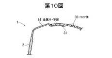
本発明では、FRP体30と金属体10との結合力を高めるために、第10,11,12図のような構成を採用してもよい。 In the present invention, in order to increase the bonding force between the
第10図では、FRP体30の内面に金属体10(この場合は金属サイド部14)の端面に当接する凸部31を設けている。 In FIG. 10, the
第11図では、FRP体30の内面に金属体10(この場合は金属サイド部14)の端縁を挟持するためのオーバーレイ部32を設けている。 In FIG. 11, an
第12図では、金属体10(この場合は金属サイド部14)に凹所14Aを設け、この凹所14Aに接着剤33を充填することにより、FRP体30と金属サイド部14とを接着している。 In FIG. 12, the metal body 10 (in this case, the metal side portion 14) is provided with a
上記実施の形態では金属クラウン部15に円形の凹穴15aを設けているが、楕円形、角形などであってもよい。また、細長い溝であってもよい。本発明では、金属クラウン部15の上面はサンドブラスト処理やサンドペーパーがけ等により粗面とされていてもよい。 In the embodiment described above, the circular
1 ゴルフクラブヘッド
2 フェース部
3 ソール部
4 サイド部
5 クラウン部
6 ホゼル部
10 金属体
13 金属ソール部
14 金属サイド部
15 金属クラウン部
15a 凹穴
17 凹所
18 環状体
20 第1のウェイト材
21 樹脂プレート
22 FRP硬化層
25 第2のウェイト材
26 金属プレート
30 FRP体DESCRIPTION OF
Claims (1)
Translated fromJapanese該クラウン部の主要部が繊維強化樹脂体よりなり、
少なくともフェース部と、該フェース部に連なる、クラウン部の前縁部とが金属製であり、
該クラウン部の前縁部を構成する金属クラウン部の上面に凹部が設けられ、該金属クラウン部の上面に対し該繊維強化樹脂体の前縁部が重なって結合されており、
該金属クラウン部の凹部は、深さが0.1〜0.3mmである凹穴であり、該金属クラウン部の全体にわたって10〜200個設けられているゴルフクラブヘッドを製造する方法であって、
該金属クラウン部の上面の凹部に粘着性を有した熱硬化性樹脂を付着させておき、該金属クラウン部の上面に対して前記繊維強化樹脂体の前縁部を重ねて加熱加圧することを特徴とするゴルフクラブヘッドの製造方法。Face portion, a sole portion, a side portion,have a crown portion and a hoselportion,
The main part of the crown part is made of a fiber-reinforced resin body,
At least a face portion, continuous with the face portion,Ri is metallic der a front edge portion of the crown portion,
A concave portion is provided on the upper surface of the metal crown portion constituting the front edge portion of the crown portion, and the front edge portion of the fiber reinforced resin body is overlapped and bonded to the upper surface of the metal crown portion,
Recesses of the metal crown portion, the depth is 0.1~0.3mm recessed hole,there a method of manufacturing theLugo Ruff club head provided 10 to 200 pieces throughout the metal crown portionAnd
A thermosetting resin having adhesiveness is attached to the concave portion on the upper surface of the metal crown portion, and the front edge portion of the fiber reinforced resin body is superposed on the upper surface of the metal crown portion and heated and pressed. A golf club head manufacturing method characterized by the above.
Priority Applications (7)
| Application Number | Priority Date | Filing Date | Title |
|---|---|---|---|
| JP2004305910AJP4639749B2 (en) | 2004-10-20 | 2004-10-20 | Manufacturing method of golf club head |
| KR1020050040933AKR20060046056A (en) | 2004-10-20 | 2005-05-17 | Golf club head |
| TW094212615UTWM291825U (en) | 2004-10-20 | 2005-07-26 | Golf club head |
| CNA2005100873367ACN1762513A (en) | 2004-10-20 | 2005-07-28 | golf club head |
| GB0521264AGB2419296B (en) | 2004-10-20 | 2005-10-19 | Golf club head |
| US11/252,801US7530901B2 (en) | 2004-10-20 | 2005-10-19 | Golf club head |
| AU2005225084AAU2005225084A1 (en) | 2004-10-20 | 2005-10-20 | Golf club head |
Applications Claiming Priority (1)
| Application Number | Priority Date | Filing Date | Title |
|---|---|---|---|
| JP2004305910AJP4639749B2 (en) | 2004-10-20 | 2004-10-20 | Manufacturing method of golf club head |
Publications (2)
| Publication Number | Publication Date |
|---|---|
| JP2006116002A JP2006116002A (en) | 2006-05-11 |
| JP4639749B2true JP4639749B2 (en) | 2011-02-23 |
Family
ID=35458280
Family Applications (1)
| Application Number | Title | Priority Date | Filing Date |
|---|---|---|---|
| JP2004305910AExpired - Fee RelatedJP4639749B2 (en) | 2004-10-20 | 2004-10-20 | Manufacturing method of golf club head |
Country Status (7)
| Country | Link |
|---|---|
| US (1) | US7530901B2 (en) |
| JP (1) | JP4639749B2 (en) |
| KR (1) | KR20060046056A (en) |
| CN (1) | CN1762513A (en) |
| AU (1) | AU2005225084A1 (en) |
| GB (1) | GB2419296B (en) |
| TW (1) | TWM291825U (en) |
Cited By (4)
| Publication number | Priority date | Publication date | Assignee | Title |
|---|---|---|---|---|
| US11266885B2 (en) | 2011-12-29 | 2022-03-08 | Taylor Made Golf Company, Inc. | Golf club head |
| US11541286B2 (en) | 2014-05-21 | 2023-01-03 | Taylor Made Golf Company, Inc. | Golf club heads |
| JP2024156819A (en)* | 2019-08-23 | 2024-11-06 | カーステン マニュファクチュアリング コーポレーション | Manufacturing method of golf club head |
| JP7755010B2 (en) | 2019-08-23 | 2025-10-15 | カーステン マニュファクチュアリング コーポレーション | Golf club head |
Families Citing this family (166)
| Publication number | Priority date | Publication date | Assignee | Title |
|---|---|---|---|---|
| US8235844B2 (en) | 2010-06-01 | 2012-08-07 | Adams Golf Ip, Lp | Hollow golf club head |
| US8900069B2 (en) | 2010-12-28 | 2014-12-02 | Taylor Made Golf Company, Inc. | Fairway wood center of gravity projection |
| JP4032424B2 (en)* | 2003-08-12 | 2008-01-16 | 株式会社遠藤製作所 | Golf club |
| US9943734B2 (en) | 2004-11-08 | 2018-04-17 | Taylor Made Golf Company, Inc. | Golf club |
| US8007371B2 (en)* | 2005-04-21 | 2011-08-30 | Cobra Golf, Inc. | Golf club head with concave insert |
| US7658686B2 (en)* | 2005-04-21 | 2010-02-09 | Acushnet Company | Golf club head with concave insert |
| US20130178306A1 (en) | 2005-04-21 | 2013-07-11 | Cobra Golf Incorporated | Golf club head with separable component |
| US7938740B2 (en) | 2005-04-21 | 2011-05-10 | Cobra Golf, Inc. | Golf club head |
| US20120172147A1 (en)* | 2009-12-21 | 2012-07-05 | Cobra Golf Incorporated | Golf club head with multi-component construction |
| US9440123B2 (en) | 2005-04-21 | 2016-09-13 | Cobra Golf Incorporated | Golf club head with accessible interior |
| US9393471B2 (en) | 2005-04-21 | 2016-07-19 | Cobra Golf Incorporated | Golf club head with removable component |
| US9421438B2 (en) | 2005-04-21 | 2016-08-23 | Cobra Golf Incorporated | Golf club head with accessible interior |
| US8938871B2 (en) | 2005-04-21 | 2015-01-27 | Cobra Golf Incorporated | Golf club head with high specific-gravity materials |
| US8523705B2 (en) | 2005-04-21 | 2013-09-03 | Cobra Golf Incorporated | Golf club head |
| US7803065B2 (en) | 2005-04-21 | 2010-09-28 | Cobra Golf, Inc. | Golf club head |
| US8303433B2 (en)* | 2005-04-21 | 2012-11-06 | Cobra Golf Incorporated | Golf club head with moveable insert |
| US7377860B2 (en)* | 2005-07-13 | 2008-05-27 | Acushnet Company | Metal wood golf club head |
| US7582024B2 (en) | 2005-08-31 | 2009-09-01 | Acushnet Company | Metal wood club |
| US8986133B2 (en) | 2012-09-14 | 2015-03-24 | Acushnet Company | Golf club head with flexure |
| US9320949B2 (en) | 2006-10-25 | 2016-04-26 | Acushnet Company | Golf club head with flexure |
| US8834289B2 (en) | 2012-09-14 | 2014-09-16 | Acushnet Company | Golf club head with flexure |
| US9498688B2 (en) | 2006-10-25 | 2016-11-22 | Acushnet Company | Golf club head with stiffening member |
| US8834290B2 (en) | 2012-09-14 | 2014-09-16 | Acushnet Company | Golf club head with flexure |
| US9636559B2 (en) | 2006-10-25 | 2017-05-02 | Acushnet Company | Golf club head with depression |
| US8636609B2 (en)* | 2006-11-30 | 2014-01-28 | Taylor Made Golf Company, Inc. | Golf club head having dent resistant thin crown |
| JP2008148762A (en)* | 2006-12-14 | 2008-07-03 | Sri Sports Ltd | Golf club head |
| US8814723B2 (en)* | 2007-04-05 | 2014-08-26 | Nike, Inc. | Rotational molded golf club heads |
| US8398506B2 (en)* | 2007-06-21 | 2013-03-19 | Nike, Inc. | Golf clubs and golf club heads |
| US8133135B2 (en) | 2007-06-21 | 2012-03-13 | Nike, Inc. | High moment of inertia wood-type golf clubs and golf club heads |
| US7662051B2 (en)* | 2007-09-11 | 2010-02-16 | Cindy Rhodes | Golf head |
| US7753806B2 (en) | 2007-12-31 | 2010-07-13 | Taylor Made Golf Company, Inc. | Golf club |
| US8206244B2 (en) | 2008-01-10 | 2012-06-26 | Adams Golf Ip, Lp | Fairway wood type golf club |
| US7993216B2 (en) | 2008-11-17 | 2011-08-09 | Nike, Inc. | Golf club head or other ball striking device having multi-piece construction |
| US9795845B2 (en) | 2009-01-20 | 2017-10-24 | Karsten Manufacturing Corporation | Golf club and golf club head structures |
| US9149693B2 (en) | 2009-01-20 | 2015-10-06 | Nike, Inc. | Golf club and golf club head structures |
| US8668595B2 (en) | 2011-04-28 | 2014-03-11 | Nike, Inc. | Golf clubs and golf club heads |
| US9192831B2 (en) | 2009-01-20 | 2015-11-24 | Nike, Inc. | Golf club and golf club head structures |
| US8758156B2 (en) | 2009-05-13 | 2014-06-24 | Nike, Inc. | Golf club assembly and golf club with aerodynamic features |
| US8366565B2 (en) | 2009-05-13 | 2013-02-05 | Nike, Inc. | Golf club assembly and golf club with aerodynamic features |
| US8162775B2 (en) | 2009-05-13 | 2012-04-24 | Nike, Inc. | Golf club assembly and golf club with aerodynamic features |
| US8821309B2 (en) | 2009-05-13 | 2014-09-02 | Nike, Inc. | Golf club assembly and golf club with aerodynamic features |
| WO2011011699A1 (en) | 2009-07-24 | 2011-01-27 | Nike International, Ltd. | Golf club head or other ball striking device having impact-influence body features |
| US8197357B1 (en) | 2009-12-16 | 2012-06-12 | Callaway Golf Company | Golf club head with composite weight port |
| US8540588B2 (en) | 2009-12-16 | 2013-09-24 | Bradley C. Rice | Golf club head with composite weight port |
| USD628257S1 (en) | 2010-02-04 | 2010-11-30 | Adams Golf I.P., Lp | Crown channel for a golf club head |
| USD631119S1 (en) | 2010-02-04 | 2011-01-18 | Adams Golf Ip, Lp | Crown channel for golf club head |
| USD630696S1 (en) | 2010-02-04 | 2011-01-11 | Adams Golf Ip, Lp | Crown channel for golf club head |
| USD630278S1 (en) | 2010-02-04 | 2011-01-04 | Adams Golf I.P., Lp | Crown channel for golf club head |
| US8632419B2 (en)* | 2010-03-05 | 2014-01-21 | Callaway Golf Company | Golf club head |
| US8821312B2 (en) | 2010-06-01 | 2014-09-02 | Taylor Made Golf Company, Inc. | Golf club head having a stress reducing feature with aperture |
| US9089749B2 (en) | 2010-06-01 | 2015-07-28 | Taylor Made Golf Company, Inc. | Golf club head having a shielded stress reducing feature |
| US8827831B2 (en) | 2010-06-01 | 2014-09-09 | Taylor Made Golf Company, Inc. | Golf club head having a stress reducing feature |
| US8491416B1 (en) | 2010-08-20 | 2013-07-23 | Callaway Golf Company | Golf club head |
| US8747253B2 (en)* | 2010-09-30 | 2014-06-10 | Nike, Inc. | Golf club head or other ball striking device having adjustable weighting features |
| US9687705B2 (en) | 2010-11-30 | 2017-06-27 | Nike, Inc. | Golf club head or other ball striking device having impact-influencing body features |
| EP2646122B1 (en) | 2010-11-30 | 2015-03-18 | NIKE Innovate C.V. | Golf club heads or other ball striking devices having distributed impact response and a stiffened face plate |
| JP5749479B2 (en)* | 2010-12-07 | 2015-07-15 | ブリヂストンスポーツ株式会社 | Golf club head |
| US8888607B2 (en) | 2010-12-28 | 2014-11-18 | Taylor Made Golf Company, Inc. | Fairway wood center of gravity projection |
| US9220953B2 (en) | 2010-12-28 | 2015-12-29 | Taylor Made Golf Company, Inc. | Fairway wood center of gravity projection |
| US10639524B2 (en) | 2010-12-28 | 2020-05-05 | Taylor Made Golf Company, Inc. | Golf club head |
| US9707457B2 (en) | 2010-12-28 | 2017-07-18 | Taylor Made Golf Company, Inc. | Golf club |
| US9101808B2 (en) | 2011-01-27 | 2015-08-11 | Nike, Inc. | Golf club head or other ball striking device having impact-influencing body features |
| KR101236019B1 (en)* | 2011-04-19 | 2013-02-21 | 이만호 | Method of diamond combined golf club for improving accuracy of swing spot and golf club using the same |
| US9433844B2 (en) | 2011-04-28 | 2016-09-06 | Nike, Inc. | Golf clubs and golf club heads |
| US9409076B2 (en) | 2011-04-28 | 2016-08-09 | Nike, Inc. | Golf clubs and golf club heads |
| US9409073B2 (en) | 2011-04-28 | 2016-08-09 | Nike, Inc. | Golf clubs and golf club heads |
| US9433845B2 (en) | 2011-04-28 | 2016-09-06 | Nike, Inc. | Golf clubs and golf club heads |
| US9375624B2 (en) | 2011-04-28 | 2016-06-28 | Nike, Inc. | Golf clubs and golf club heads |
| USD655363S1 (en) | 2011-05-11 | 2012-03-06 | Adams Golf Ip, Lp | Stepped crown channel for a golf club head |
| US9211448B2 (en) | 2011-08-10 | 2015-12-15 | Acushnet Company | Golf club head with flexure |
| CN107583254B (en) | 2011-08-23 | 2020-03-27 | 耐克创新有限合伙公司 | Golf club head with cavity |
| US9573027B2 (en) | 2011-08-23 | 2017-02-21 | Sri Sports Limited | Weight member for a golf club head |
| US8956242B2 (en)* | 2011-12-21 | 2015-02-17 | Callaway Golf Company | Golf club head |
| US8403771B1 (en)* | 2011-12-21 | 2013-03-26 | Callaway Gold Company | Golf club head |
| US8858360B2 (en)* | 2011-12-21 | 2014-10-14 | Callaway Golf Company | Golf club head |
| US9700770B2 (en) | 2011-12-27 | 2017-07-11 | Acushnet Company | Golf club having removeable weight |
| US9095753B2 (en)* | 2011-12-27 | 2015-08-04 | Acushnet Company | Golf club having removable weight |
| US11213730B2 (en) | 2018-12-13 | 2022-01-04 | Acushnet Company | Golf club head with improved inertia performance |
| US9205312B2 (en) | 2011-12-27 | 2015-12-08 | Acushnet Company | Golf club having removable weight |
| USD686679S1 (en) | 2012-03-21 | 2013-07-23 | Taylor Made Golf Company, Inc. | Golf club head |
| USD692077S1 (en) | 2012-03-21 | 2013-10-22 | Taylor Made Golf Company, Inc. | Golf club head |
| USD675272S1 (en) | 2012-03-21 | 2013-01-29 | Taylor Made Golf Company, Inc. | Golf club head |
| US8870679B2 (en) | 2012-05-31 | 2014-10-28 | Nike, Inc. | Golf club assembly and golf club with aerodynamic features |
| US9403069B2 (en) | 2012-05-31 | 2016-08-02 | Nike, Inc. | Golf club head or other ball striking device having impact-influencing body features |
| US8932149B2 (en) | 2012-05-31 | 2015-01-13 | Nike, Inc. | Golf club assembly and golf club with aerodynamic features |
| US9101811B1 (en)* | 2012-06-08 | 2015-08-11 | Callaway Golf Company | CG height adjustability by conformal weighting |
| US8926450B2 (en)* | 2012-06-11 | 2015-01-06 | Bridgestone Sports Co., Ltd. | Golf club head |
| US9636552B2 (en) | 2012-09-14 | 2017-05-02 | Acushnet Company | Golf club head with flexure |
| US8961332B2 (en) | 2012-09-14 | 2015-02-24 | Acushnet Company | Golf club head with flexure |
| US10806978B2 (en) | 2012-09-14 | 2020-10-20 | Acushnet Company | Golf club head with flexure |
| US10099092B2 (en) | 2012-09-14 | 2018-10-16 | Acushnet Company | Golf club with flexure |
| US9682293B2 (en) | 2012-09-14 | 2017-06-20 | Acushnet Company | Golf club head with flexure |
| US9700765B2 (en) | 2012-09-14 | 2017-07-11 | Acushnet Company | Golf club head with flexure |
| US10343032B2 (en) | 2012-09-14 | 2019-07-09 | Acushnet Company | Golf club with flexure |
| US9675850B2 (en) | 2012-09-14 | 2017-06-13 | Acushnet Company | Golf club head with flexure |
| US10343033B2 (en) | 2012-09-14 | 2019-07-09 | Acushnet Company | Golf club head with flexure |
| US9421433B2 (en) | 2012-09-14 | 2016-08-23 | Acushnet Company | Golf club head with flexure |
| US9839820B2 (en) | 2012-09-14 | 2017-12-12 | Acushnet Company | Golf club head with flexure |
| US10843046B2 (en) | 2012-09-14 | 2020-11-24 | Acushnet Company | Golf club with flexure |
| USD697152S1 (en) | 2012-10-18 | 2014-01-07 | Taylor Made Golf Company, Inc. | Golf club head |
| USD696367S1 (en) | 2012-11-07 | 2013-12-24 | Taylor Made Golf Company, Inc. | Golf club head |
| US8696491B1 (en)* | 2012-11-16 | 2014-04-15 | Callaway Golf Company | Golf club head with adjustable center of gravity |
| JP6027993B2 (en)* | 2013-03-16 | 2016-11-16 | アクシュネット カンパニーAcushnet Company | Golf club head with bend |
| JP2015033474A (en)* | 2013-08-08 | 2015-02-19 | ダンロップスポーツ株式会社 | Golf club head |
| US9937395B2 (en)* | 2013-11-12 | 2018-04-10 | Taylor Made Golf Company, Inc. | Golf club |
| US20150290503A1 (en)* | 2014-04-11 | 2015-10-15 | Chi-Hung Su | Top crown of a golf club head |
| US9975011B1 (en) | 2014-05-21 | 2018-05-22 | Taylor Made Golf Company, Inc. | Golf club |
| US10245474B2 (en) | 2014-06-20 | 2019-04-02 | Karsten Manufacturing Corporation | Golf club head or other ball striking device having impact-influencing body features |
| US9914026B2 (en) | 2014-06-20 | 2018-03-13 | Karsten Manufacturing Corporation | Golf club head or other ball striking device having impact-influencing body features |
| US20150367204A1 (en) | 2014-06-20 | 2015-12-24 | Nike, Inc. | Golf Club Head or Other Ball Striking Device Having Impact-Influencing Body Features |
| USD731606S1 (en) | 2014-06-23 | 2015-06-09 | Taylor Made Golf Company, Inc. | Iron club head |
| USD737912S1 (en) | 2014-06-23 | 2015-09-01 | Taylor Made Golf Company, Inc. | Iron club head |
| USD735284S1 (en) | 2014-06-23 | 2015-07-28 | Taylor Made Golf Company, Inc. | Iron club head |
| USD737913S1 (en) | 2014-06-23 | 2015-09-01 | Taylor Made Golf Company, Inc. | Iron club head |
| US10065082B2 (en) | 2014-07-22 | 2018-09-04 | Taylor Made Golf Company, Inc. | Golf club |
| USD726857S1 (en)* | 2014-08-29 | 2015-04-14 | Nike, Inc. | Golf club head |
| USD724165S1 (en)* | 2014-08-29 | 2015-03-10 | Nike, Inc. | Golf club head |
| US9526956B2 (en) | 2014-09-05 | 2016-12-27 | Acushnet Company | Golf club head |
| US9925428B2 (en) | 2015-05-29 | 2018-03-27 | Karsten Manufacturing Corporation | Golf club head or other ball striking device having impact-influencing body features |
| USD772996S1 (en) | 2015-07-16 | 2016-11-29 | Taylor Made Golf Company, Inc. | Golf club head |
| US10035048B2 (en)* | 2015-08-13 | 2018-07-31 | Karsten Manufacturing Corporation | Golf club head with transition profiles to reduce aerodynamic drag |
| US10874914B2 (en)* | 2015-08-14 | 2020-12-29 | Taylor Made Golf Company, Inc. | Golf club head |
| US9914027B1 (en) | 2015-08-14 | 2018-03-13 | Taylor Made Golf Company, Inc. | Golf club head |
| US10183202B1 (en)* | 2015-08-14 | 2019-01-22 | Taylor Made Golf Company, Inc. | Golf club head |
| US10258842B2 (en)* | 2015-12-07 | 2019-04-16 | Karsten Manufacturing Corporation | Golf club head including mechanical and adhesive joints |
| US10035051B2 (en) | 2015-12-22 | 2018-07-31 | Acushnet Company | Golf club with movable weight |
| US9914028B1 (en) | 2016-09-06 | 2018-03-13 | Acushnet Company | Golf club with movable weight |
| US9975019B2 (en) | 2015-12-22 | 2018-05-22 | Acushnet Company | Golf club with movable weight |
| US9744415B2 (en) | 2015-12-22 | 2017-08-29 | Acushnet Company | Golf club having removable weight |
| KR102377351B1 (en) | 2016-05-27 | 2022-03-22 | 카스턴 매뉴팩츄어링 코오포레이숀 | Mixed Material Golf Club Head |
| US11969632B2 (en) | 2016-05-27 | 2024-04-30 | Karsten Manufacturing Corporation | Mixed material golf club head |
| US10828543B2 (en) | 2016-05-27 | 2020-11-10 | Karsten Manufacturing Corporation | Mixed material golf club head |
| US10596427B2 (en)* | 2017-12-08 | 2020-03-24 | Karsten Manufacturing Corporation | Multi-component golf club head |
| US11819743B2 (en) | 2016-05-27 | 2023-11-21 | Karsten Manufacturing Corporation | Mixed material golf club head |
| US11517799B2 (en) | 2017-12-08 | 2022-12-06 | Karsten Manufacturing Corporation | Multi-component golf club head |
| US10940374B2 (en) | 2016-05-27 | 2021-03-09 | Karsten Manufacturing Corporation | Mixed material golf club head |
| US10940373B2 (en) | 2016-05-27 | 2021-03-09 | Karsten Manufacturing Corporation | Mixed material golf club head |
| US10987551B2 (en)* | 2017-12-08 | 2021-04-27 | Karsten Manufacturing Corporation | Golf club heads with stiffening ribs |
| USD813328S1 (en) | 2016-09-02 | 2018-03-20 | Callaway Golf Company | Golf club head |
| US10463927B2 (en)* | 2016-12-06 | 2019-11-05 | Taylor Made Golf Company, Inc. | Golf club head |
| US10207160B2 (en) | 2016-12-30 | 2019-02-19 | Taylor Made Golf Company, Inc. | Golf club heads |
| US20180345099A1 (en) | 2017-06-05 | 2018-12-06 | Taylor Made Golf Company, Inc. | Golf club heads |
| JP6931187B2 (en)* | 2017-07-13 | 2021-09-01 | 住友ゴム工業株式会社 | Iron type golf club head |
| US11839802B2 (en) | 2017-12-08 | 2023-12-12 | Karsten Manufacturing Corporation | Multi-component golf club head |
| US12029951B2 (en) | 2017-12-14 | 2024-07-09 | Bauer Hockey, Llc | Hockey stick and blade for hockey stick |
| US12042706B2 (en)* | 2017-12-14 | 2024-07-23 | Bauer Hockey, Llc | Hockey stick with variable stiffness blade |
| JP7244528B2 (en) | 2018-01-19 | 2023-03-22 | カーステン マニュファクチュアリング コーポレーション | Golf club head including thermoplastic composite |
| GB2583862B (en) | 2018-01-19 | 2022-08-10 | Karsten Mfg Corp | Mixed material golf club head |
| US10583334B2 (en)* | 2018-03-06 | 2020-03-10 | Acushnet Company | Golf club having a low modulus crown |
| US10653926B2 (en) | 2018-07-23 | 2020-05-19 | Taylor Made Golf Company, Inc. | Golf club heads |
| US10369437B1 (en) | 2018-08-20 | 2019-08-06 | Acushnet Company | Wood-type golf club including center of gravity adjustment |
| US20220134197A1 (en)* | 2018-12-13 | 2022-05-05 | Acushnet Company | Golf club head with improved inertia performance |
| US20220226702A1 (en)* | 2018-12-13 | 2022-07-21 | Acushnet Company | Golf club head with improved inertia performance |
| EP3897882B1 (en)* | 2018-12-21 | 2024-11-13 | Karsten Manufacturing Corporation | Golf club head with stiffening ribs |
| USD916992S1 (en) | 2019-08-09 | 2021-04-20 | Karsten Manufacturing Corporation | Multi-component golf club head |
| USD919024S1 (en) | 2019-08-09 | 2021-05-11 | Karsten Manufacturing Corporation | Multi-component golf club head |
| TWI729927B (en)* | 2020-08-28 | 2021-06-01 | 明安國際企業股份有限公司 | Golf club head |
| GB2614473A (en)* | 2020-09-10 | 2023-07-05 | Karsten Mfg Corp | Fairway wood golf club head with low CG |
| GB2614502A (en)* | 2020-09-24 | 2023-07-05 | Karsten Mfg Corp | Multi-component golf club head with tuning element |
| TWI742953B (en)* | 2020-12-07 | 2021-10-11 | 明安國際企業股份有限公司 | Golf club head |
| US11406881B2 (en) | 2020-12-28 | 2022-08-09 | Taylor Made Golf Company, Inc. | Golf club heads |
| US11759685B2 (en) | 2020-12-28 | 2023-09-19 | Taylor Made Golf Company, Inc. | Golf club heads |
| JP2023028131A (en)* | 2021-08-18 | 2023-03-03 | 住友ゴム工業株式会社 | golf club head |
| US11679313B2 (en) | 2021-09-24 | 2023-06-20 | Acushnet Company | Golf club head |
| US12208317B2 (en)* | 2022-04-20 | 2025-01-28 | Acushnet Company | Multi-material golf club head |
| US11794082B1 (en)* | 2022-06-03 | 2023-10-24 | Mizuno Corporation | Golf club head with sole side features |
Family Cites Families (85)
| Publication number | Priority date | Publication date | Assignee | Title |
|---|---|---|---|---|
| US3652094A (en)* | 1969-10-21 | 1972-03-28 | Cecil C Glover | Golf club with adjustable weighting plugs |
| US4021047A (en)* | 1976-02-25 | 1977-05-03 | Mader Robert J | Golf driver club |
| US4432549A (en)* | 1978-01-25 | 1984-02-21 | Pro-Pattern, Inc. | Metal golf driver |
| US4438931A (en)* | 1982-09-16 | 1984-03-27 | Kabushiki Kaisha Endo Seisakusho | Golf club head |
| US5255913A (en)* | 1989-10-09 | 1993-10-26 | Yamaha Corporation | Wood golf club head |
| JPH0489071A (en) | 1990-07-31 | 1992-03-23 | Yamaha Corp | Wood club head for golf |
| JPH0798076B2 (en)* | 1990-09-27 | 1995-10-25 | ヤマハ株式会社 | Golf club head |
| JPH0568725A (en) | 1991-09-13 | 1993-03-23 | Olympic Co Ltd | Wood club head for golf |
| JP2508562B2 (en) | 1992-01-10 | 1996-06-19 | ヤマハ株式会社 | Manufacturing method of fiber reinforced thermoplastic resin molded products |
| FR2689407A1 (en)* | 1992-04-01 | 1993-10-08 | Taylor Made Golf Co | Golf club head composed of a plastic hollow body and a sealing element. |
| FR2689406B1 (en)* | 1992-04-01 | 1994-06-03 | Taylor Made Golf Co | GOLF CLUB HEAD COMPOSED OF AN INTERNAL SUB-ASSEMBLY AND AN EXTERNAL ENVELOPE. |
| JPH07406U (en) | 1993-05-31 | 1995-01-06 | 光男 羅 | Golf club head |
| JPH07112042A (en) | 1993-10-19 | 1995-05-02 | Bridgestone Sports Co Ltd | Golf club head |
| JP2949691B2 (en) | 1993-10-19 | 1999-09-20 | ブリヂストンスポーツ株式会社 | Golf club head |
| JPH07155410A (en) | 1993-12-06 | 1995-06-20 | Yokohama Rubber Co Ltd:The | Golf club head |
| JPH0824377A (en) | 1994-07-20 | 1996-01-30 | Yonetsukusu Kk | Production of golf club head |
| JPH08229166A (en)* | 1995-02-27 | 1996-09-10 | Yamaha Corp | Wood club head for golf |
| JP3710102B2 (en) | 1995-08-03 | 2005-10-26 | マルマン株式会社 | Manufacturing method of golf club head made of fiber reinforced resin |
| US5624331A (en)* | 1995-10-30 | 1997-04-29 | Pro-Kennex, Inc. | Composite-metal golf club head |
| JPH09187534A (en) | 1995-11-02 | 1997-07-22 | Wyman Gordon Co | Head of golf club having face of metallic glass |
| JP3205495B2 (en)* | 1995-11-17 | 2001-09-04 | ワイケイケイ株式会社 | Golf club head |
| JPH09215786A (en) | 1996-02-15 | 1997-08-19 | Mitsubishi Materials Corp | Golf club head and production thereof |
| JP2998006B2 (en) | 1996-04-05 | 2000-01-11 | ブリヂストンスポーツ株式会社 | Golf club head |
| JPH1015119A (en) | 1996-07-09 | 1998-01-20 | Mitsubishi Materials Corp | Golf clubhead |
| JPH10192458A (en)* | 1996-12-27 | 1998-07-28 | Mizuno Corp | Golf club head and method of manufacturing the same |
| JPH10192456A (en)* | 1996-12-27 | 1998-07-28 | Mizuno Corp | Golf club head and method of manufacturing the same |
| US5766095A (en)* | 1997-01-22 | 1998-06-16 | Antonious; Anthony J. | Metalwood golf club with elevated outer peripheral weight |
| US5997415A (en)* | 1997-02-11 | 1999-12-07 | Zevo Golf Co., Inc. | Golf club head |
| JP3961788B2 (en) | 1997-04-16 | 2007-08-22 | Sriスポーツ株式会社 | Golf club head |
| DE69818374T2 (en)* | 1997-08-08 | 2004-07-01 | Sumitomo Rubber Industries Ltd., Kobe | Golf club head and process for its manufacture |
| JPH11104281A (en)* | 1997-10-01 | 1999-04-20 | Takeshi Masumoto | Golf club head |
| US6527650B2 (en)* | 1997-10-23 | 2003-03-04 | Callaway Golf Company | Internal weighting for a composite golf club head |
| US6248025B1 (en)* | 1997-10-23 | 2001-06-19 | Callaway Golf Company | Composite golf club head and method of manufacturing |
| US6406378B1 (en)* | 1997-10-23 | 2002-06-18 | Callaway Golf Company | Sound enhanced composite golf club head |
| US6010411A (en)* | 1997-10-23 | 2000-01-04 | Callaway Golf Company | Densified loaded films in composite golf club heads |
| US6244976B1 (en)* | 1997-10-23 | 2001-06-12 | Callaway Golf Company | Integral sole plate and hosel for a golf club head |
| US6607452B2 (en)* | 1997-10-23 | 2003-08-19 | Callaway Golf Company | High moment of inertia composite golf club head |
| US6254494B1 (en)* | 1998-01-30 | 2001-07-03 | Bridgestone Sports Co., Ltd. | Golf club head |
| US6354963B1 (en)* | 1998-04-10 | 2002-03-12 | Mitsubishi Rayon Co., Ltd. | Golf club head |
| JP3259136B2 (en) | 1998-05-01 | 2002-02-25 | 震昌 孫 | Golf club |
| JP2000024149A (en) | 1998-07-07 | 2000-01-25 | Makita Takanori | Golf club |
| JP2000033133A (en) | 1998-07-17 | 2000-02-02 | Bridgestone Sports Co Ltd | Golf club head |
| JP2000167090A (en) | 1998-12-11 | 2000-06-20 | Mizuno Corp | Metal wood head |
| JP2001062003A (en) | 1999-08-26 | 2001-03-13 | Daiwa Seiko Inc | Golf club head and method of manufacturing the same |
| JP2001087426A (en) | 1999-09-27 | 2001-04-03 | Sumitomo Rubber Ind Ltd | Golf club lead and golf club |
| US6575845B2 (en)* | 1999-11-01 | 2003-06-10 | Callaway Golf Company | Multiple material golf club head |
| US6565452B2 (en)* | 1999-11-01 | 2003-05-20 | Callaway Golf Company | Multiple material golf club head with face insert |
| US6582323B2 (en)* | 1999-11-01 | 2003-06-24 | Callaway Golf Company | Multiple material golf club head |
| US6354962B1 (en)* | 1999-11-01 | 2002-03-12 | Callaway Golf Company | Golf club head with a face composed of a forged material |
| US6491592B2 (en) | 1999-11-01 | 2002-12-10 | Callaway Golf Company | Multiple material golf club head |
| US6381828B1 (en)* | 1999-11-01 | 2002-05-07 | Callaway Golf Company | Chemical etching of a striking plate for a golf club head |
| US6440011B1 (en)* | 1999-11-01 | 2002-08-27 | Callaway Golf Company | Method for processing a striking plate for a golf club head |
| US6435977B1 (en)* | 1999-11-01 | 2002-08-20 | Callaway Golf Company | Set of woods with face thickness variation based on loft angle |
| US6371868B1 (en)* | 1999-11-01 | 2002-04-16 | Callaway Golf Company | Internal off-set hosel for a golf club head |
| TW577761B (en)* | 1999-11-01 | 2004-03-01 | Callaway Golf Co | Multiple material golf club head |
| US6663504B2 (en)* | 1999-11-01 | 2003-12-16 | Callaway Golf Company | Multiple material golf club head |
| US6739984B1 (en)* | 1999-11-30 | 2004-05-25 | Thunder Golf, L.L.C. | Golf club head |
| JP3584189B2 (en) | 1999-11-30 | 2004-11-04 | ダイワ精工株式会社 | Golf club head |
| JP2001309998A (en) | 2000-02-21 | 2001-11-06 | Yokohama Rubber Co Ltd:The | Golf club head |
| JP2001321474A (en) | 2000-05-18 | 2001-11-20 | Sumitomo Rubber Ind Ltd | Golf club head |
| TW450822B (en)* | 2000-05-31 | 2001-08-21 | Advanced Internatioanl Multite | Method for integrally forming golf club head and its structure |
| JP2002000773A (en) | 2000-06-19 | 2002-01-08 | Mizuno Corp | Metal wood head |
| JP2002017908A (en)* | 2000-07-07 | 2002-01-22 | Endo Mfg Co Ltd | Golf club and manufacturing method thereof |
| JP2002136625A (en)* | 2000-11-06 | 2002-05-14 | Mizuno Corp | Golf club |
| US6524194B2 (en)* | 2001-01-18 | 2003-02-25 | Acushnet Company | Golf club head construction |
| US20020160858A1 (en)* | 2001-04-27 | 2002-10-31 | Hou-Teng Lee | Golf club head and process for making the same |
| JP2002224249A (en) | 2001-02-07 | 2002-08-13 | Sumitomo Rubber Ind Ltd | Golf club head manufacturing method |
| US6623378B2 (en)* | 2001-06-11 | 2003-09-23 | Taylor Made Golf Company, Inc. | Method for manufacturing and golf club head |
| JP2003024484A (en)* | 2001-07-12 | 2003-01-28 | Gps:Kk | Golf club head and its manufacturing method |
| JP4098583B2 (en) | 2001-08-28 | 2008-06-11 | 美津濃株式会社 | Manufacturing method of golf club head |
| KR100596958B1 (en)* | 2001-10-24 | 2006-07-07 | 요코하마 고무 가부시키가이샤 | Golf club head |
| KR100596960B1 (en)* | 2001-12-28 | 2006-07-07 | 요코하마 고무 가부시키가이샤 | Hollow golf club head |
| US7037214B2 (en)* | 2001-12-28 | 2006-05-02 | The Yokohama Rubber Co., Ltd. | Hollow golf club head |
| JP3725481B2 (en)* | 2002-01-11 | 2005-12-14 | 横浜ゴム株式会社 | Hollow golf club head |
| US6602149B1 (en)* | 2002-03-25 | 2003-08-05 | Callaway Golf Company | Bonded joint design for a golf club head |
| US6648774B1 (en)* | 2002-05-01 | 2003-11-18 | Callaway Golf Company | Composite golf club head having a metal striking insert within the front face wall |
| JP2003320060A (en)* | 2002-05-02 | 2003-11-11 | Mitsubishi Rayon Co Ltd | Golf club head |
| JP2004016654A (en) | 2002-06-19 | 2004-01-22 | Bridgestone Sports Co Ltd | Golf club head |
| JP2004065810A (en) | 2002-08-09 | 2004-03-04 | Seiko S-Yard Co Ltd | Golf club head |
| JP2004180759A (en)* | 2002-11-29 | 2004-07-02 | Mizuno Corp | Golf club head and golf club |
| KR100779414B1 (en)* | 2002-12-06 | 2007-11-28 | 요코하마 고무 가부시키가이샤 | Golf club head and golf club |
| US6969326B2 (en)* | 2002-12-11 | 2005-11-29 | Taylor Made Golf Company, Inc. | Golf club head |
| JP2004305724A (en) | 2003-03-27 | 2004-11-04 | Mizuno Corp | Golf club head and golf club |
| JP2005058748A (en)* | 2003-07-31 | 2005-03-10 | Sumitomo Rubber Ind Ltd | Golf club head |
| JP4202888B2 (en)* | 2003-10-23 | 2008-12-24 | Sriスポーツ株式会社 | Golf club head |
- 2004
- 2004-10-20JPJP2004305910Apatent/JP4639749B2/ennot_activeExpired - Fee Related
- 2005
- 2005-05-17KRKR1020050040933Apatent/KR20060046056A/ennot_activeWithdrawn
- 2005-07-26TWTW094212615Upatent/TWM291825U/ennot_activeIP Right Cessation
- 2005-07-28CNCNA2005100873367Apatent/CN1762513A/enactivePending
- 2005-10-19USUS11/252,801patent/US7530901B2/ennot_activeExpired - Fee Related
- 2005-10-19GBGB0521264Apatent/GB2419296B/ennot_activeExpired - Fee Related
- 2005-10-20AUAU2005225084Apatent/AU2005225084A1/ennot_activeAbandoned
Cited By (6)
| Publication number | Priority date | Publication date | Assignee | Title |
|---|---|---|---|---|
| US11266885B2 (en) | 2011-12-29 | 2022-03-08 | Taylor Made Golf Company, Inc. | Golf club head |
| US12290723B2 (en) | 2011-12-29 | 2025-05-06 | Taylor Made Golf Company, Inc. | Golf club head |
| US11541286B2 (en) | 2014-05-21 | 2023-01-03 | Taylor Made Golf Company, Inc. | Golf club heads |
| US12324966B2 (en) | 2014-05-21 | 2025-06-10 | Taylor Made Golf Company, Inc. | Golf club heads |
| JP2024156819A (en)* | 2019-08-23 | 2024-11-06 | カーステン マニュファクチュアリング コーポレーション | Manufacturing method of golf club head |
| JP7755010B2 (en) | 2019-08-23 | 2025-10-15 | カーステン マニュファクチュアリング コーポレーション | Golf club head |
Also Published As
| Publication number | Publication date |
|---|---|
| AU2005225084A1 (en) | 2006-05-04 |
| GB0521264D0 (en) | 2005-11-30 |
| GB2419296B (en) | 2009-06-03 |
| US20060084525A1 (en) | 2006-04-20 |
| GB2419296A (en) | 2006-04-26 |
| US7530901B2 (en) | 2009-05-12 |
| KR20060046056A (en) | 2006-05-17 |
| TWM291825U (en) | 2006-06-11 |
| CN1762513A (en) | 2006-04-26 |
| JP2006116002A (en) | 2006-05-11 |
Similar Documents
| Publication | Publication Date | Title |
|---|---|---|
| JP4639749B2 (en) | Manufacturing method of golf club head | |
| US7530903B2 (en) | Golf club head | |
| US7455600B2 (en) | Golf club head | |
| US7147576B2 (en) | Golf club head | |
| US7252599B2 (en) | Golf club head | |
| US7128662B2 (en) | Golf club head | |
| JP4287769B2 (en) | Golf club head and manufacturing method thereof | |
| JP2005058748A (en) | Golf club head | |
| US9283449B1 (en) | Golf club head with composite face | |
| JP2005287664A (en) | Golf club head | |
| JP2004329544A (en) | Golf club head | |
| JP2003320060A (en) | Golf club head | |
| JP4634828B2 (en) | Golf club head | |
| JP4714293B2 (en) | Manufacturing method of golf club head | |
| JP4019676B2 (en) | Golf club head | |
| JP2005253606A (en) | Golf club head | |
| JP4550452B2 (en) | Manufacturing method of golf club head | |
| JP2005296043A (en) | Golf club head and manufacturing method thereof | |
| JP2005168565A (en) | Manufacturing method of golf club head | |
| JP2006230573A (en) | Golf club head | |
| JP2008183436A (en) | Manufacturing method of golf club head |
Legal Events
| Date | Code | Title | Description |
|---|---|---|---|
| A621 | Written request for application examination | Free format text:JAPANESE INTERMEDIATE CODE: A621 Effective date:20070918 | |
| A977 | Report on retrieval | Free format text:JAPANESE INTERMEDIATE CODE: A971007 Effective date:20100125 | |
| A131 | Notification of reasons for refusal | Free format text:JAPANESE INTERMEDIATE CODE: A131 Effective date:20100202 | |
| A521 | Request for written amendment filed | Free format text:JAPANESE INTERMEDIATE CODE: A523 Effective date:20100325 | |
| A02 | Decision of refusal | Free format text:JAPANESE INTERMEDIATE CODE: A02 Effective date:20100810 | |
| A521 | Request for written amendment filed | Free format text:JAPANESE INTERMEDIATE CODE: A523 Effective date:20101007 | |
| A911 | Transfer to examiner for re-examination before appeal (zenchi) | Free format text:JAPANESE INTERMEDIATE CODE: A911 Effective date:20101018 | |
| TRDD | Decision of grant or rejection written | ||
| A01 | Written decision to grant a patent or to grant a registration (utility model) | Free format text:JAPANESE INTERMEDIATE CODE: A01 Effective date:20101102 | |
| A01 | Written decision to grant a patent or to grant a registration (utility model) | Free format text:JAPANESE INTERMEDIATE CODE: A01 | |
| A61 | First payment of annual fees (during grant procedure) | Free format text:JAPANESE INTERMEDIATE CODE: A61 Effective date:20101115 | |
| R150 | Certificate of patent or registration of utility model | Ref document number:4639749 Country of ref document:JP Free format text:JAPANESE INTERMEDIATE CODE: R150 Free format text:JAPANESE INTERMEDIATE CODE: R150 | |
| FPAY | Renewal fee payment (event date is renewal date of database) | Free format text:PAYMENT UNTIL: 20131210 Year of fee payment:3 | |
| R250 | Receipt of annual fees | Free format text:JAPANESE INTERMEDIATE CODE: R250 | |
| R250 | Receipt of annual fees | Free format text:JAPANESE INTERMEDIATE CODE: R250 | |
| R250 | Receipt of annual fees | Free format text:JAPANESE INTERMEDIATE CODE: R250 | |
| R250 | Receipt of annual fees | Free format text:JAPANESE INTERMEDIATE CODE: R250 | |
| R250 | Receipt of annual fees | Free format text:JAPANESE INTERMEDIATE CODE: R250 | |
| R250 | Receipt of annual fees | Free format text:JAPANESE INTERMEDIATE CODE: R250 | |
| R250 | Receipt of annual fees | Free format text:JAPANESE INTERMEDIATE CODE: R250 | |
| R250 | Receipt of annual fees | Free format text:JAPANESE INTERMEDIATE CODE: R250 | |
| R250 | Receipt of annual fees | Free format text:JAPANESE INTERMEDIATE CODE: R250 | |
| LAPS | Cancellation because of no payment of annual fees |